Article

Fabrication of Polysaccharide-Based Coaxial Fibers Using Wet Spinning Processes and Their Protein Loading Properties

1
Department of Industrial Chemistry, Faculty of Engineering, Tokyo University of Science, 6-3-1 Niijuku, Katsushika-ku, Tokyo 125-8585, Japan
2
Graduate School of Engineering, Tokyo University of Science, 6-3-1 Niijuku, Katsushika-ku, Tokyo 125-8585, Japan
*
Author to whom correspondence should be addressed.
Current address: Faculty of Engineering, Yokohama National University, 79-5, Tokiwadai, Hodogaya-ku, Yokohama 240-8501, Japan.
Appl. Sci. 2023, 13(14), 8053; https://doi.org/10.3390/app13148053
Submission received: 31 May 2023 / Revised: 7 July 2023 / Accepted: 9 July 2023 / Published: 10 July 2023
(This article belongs to the Special Issue Modern Biomaterials: Latest Advances and Prospects)

Abstract

:
Fibers composed of polysaccharides are a promising candidate to be applied for biomaterials such as absorbable surgical sutures, textile fabrics, and hierarchical three-dimensional scaffolds. In this work, in order to fabricate biocompatible fibers with controlled-release abilities, the fabrication of coaxial fibers of calcium alginate (ALG-Ca) and polyion complexes (PICs) consisting of chitosan (CHI) and chondroitin sulfate C (CS), denoted as ALG-PIC fibers, by using a wet spinning process, and the evaluation of their molecular loading and release behavior were performed. The diameter and mechanical strength of the obtained ALG-PIC fibers increased with increasing concentrations of the CHI solution for PIC coatings. This indicated that higher concentrations of the CHI solution afforded a thicker PIC coating layer. Further, fluorescein isothiocyanate labeled-bovine serum albumin (FITC-BSA)-loaded ALG-PIC fibers were successfully prepared. The release behavior of FITC-BSA in the fibers exhibited a slower rate at the initial state than that in ALG-Ca, indicating that PIC coatings suppressed an initial burst release of the loading molecules. Accordingly, the fabricated coaxial fibers can be utilized as sustained-release drug carriers.

1. Introduction

Natural polymers possess biocompatibility and biodegradability. Therefore, they can be used as feedstock for biomaterials [1,2]. In particular, polysaccharides are abundant in nature and have been used as materials for paper and cloth since ancient times. In recent years, polysaccharides have been applied to biomaterials such as drug delivery systems (DDS) [3,4,5,6], tissue engineering [7,8], and wound dressings [9,10]. These biomaterials are used in various structural forms such as bulks [11], nanocomposites [12], gels [13], films [14], porous materials [15], and fibers [16]. Thus, the moldability of raw materials is essential. Cellulose and chitin, which are naturally abundant polysaccharides, are insoluble in water and difficult to mold. On the other hand, polysaccharides that have ionic functional groups in their molecules, such as chitosan (CHI), sodium alginate (ALG), and chondroitin sulfate C sodium salts (CS) are soluble in water and easy to mold. These polysaccharides can interact with inorganic ions, proteins, and oppositely charged polysaccharides, through electrostatic interactions [17,18,19]. This property enables the fabrication of gel-like, film-like, and fiber-like structural materials. For example, ALG, which is a block copolymer composed of two uronic acids, β-D-mannuronic acid and α-L-guluronic acid (Figure 1) [20], forms a cross-linked water-insoluble gel with Ca2+, i.e., calcium alginate (ALG-Ca) [20,21].
CHI is a polysaccharide consisting of glucosamines, which has an amino group. Therefore, CHI is one of the basic polymers among bio-derived polysaccharides which has positive charges in an acidic solution [22,23] and also has potential for fast gelation in acidic solutions [24]. CHI can form polyion complexes (PICs), a water-insoluble gel, by electrostatic interactions with negatively charged acidic polymers such as hyaluronic acid (HYA), CS, and ALG in aqueous solutions [25,26]. We have reported on the fabrication of polysaccharide composite materials made from polysaccharide PICs [27,28,29,30,31,32,33]. For example, polysaccharide composite films consisting of CS or HYA were successfully prepared using hot-press techniques. Composite films with charged polysaccharides have also been fabricated by layer-by-layer (LbL) assemblies [34,35,36]. However, the process generally provides thinner films than those obtained by hot-press techniques. Further, hot-press techniques have the advantage that these processes are simple and can provide free-standing films. The obtained films showed swelling properties depending on the solution condition [27,28,32], molecular permeability [29,31], and drug-loading and sustained-release abilities [30]. We also reported the fabrication of polysaccharide composite films with mechanical anisotropy using roll-press (heat-stretching) techniques [33]. These polysaccharide composite films are expected to be applied in biomaterials such as drug carriers and wound dressings.
Fibers are one candidate of the many forms of polysaccharide composite materials. Biocompatible fibers are expected to be used as absorbable surgical sutures and sustained drug release carriers. Fibers derived from polysaccharides can also be used as raw materials in more complex structures such as woven fabrics, non-woven fabrics, and hierarchical three-dimensional structures. The fabrication of polysaccharide microfibers such as those derived from CHI [37,38] and ALG-Ca [39,40] by solution spinning and polysaccharide nanofibers made of CHI [41,42] by electrospinning have been reported. In addition, fabrication of composite fibers, which are composed of two or more raw materials, have also attracted attention [43,44,45,46]. In particular, Yamamoto and coworkers reported on the fabrication of PIC fibers composed of polysaccharides [43,44]. We prepared the polysaccharide composite fibers made from PICs using the interfacial spinning method, where the CS solution was slowly placed onto the CHI solution to make an interface, and the PIC film formed at the interface was pulled up and spun [47,48]. The obtained fibers showed high mechanical strength and swelled in water. We also prepared PIC fibers using a microfluidic device [49,50]. However, few examples of fabrication and the functional evaluation of fibers composed of polysaccharide PICs have been reported; there is a necessity for further development.
In this study, we designed and fabricated a smart fiber, which is a fiber with controllable drug release ability, utilizing polysaccharide PICs. Firstly, ALG-Ca fibers were prepared by solution spinning, which were then coated with PIC films made of CS and CHI. The PIC films possess smooth structures and high mechanical strength, and thus coatings of PIC layers are expected to afford the ALG-Ca fibers not only sustained release ability but also sufficient mechanical strength. Additionally, CHI in the PICs can electrostatically interact with ALG-Ca, resulting in good mechanical properties of the fibers. The PIC thin layers were formed at the solution interface and pulled up simultaneously with ALG-Ca fibers, which resulted in the fabrication of coaxial fibers of PIC-coated ALG-Ca (ALG-PIC fiber). Further, the fabrication of ALG-PIC fibers with different thicknesses of PIC layers on ALG-Ca fiber using different concentrations of the CHI solution used to fabricate the PIC film was also conducted. Such a post-coating approach is advantageous for controlling the thickness of the coating layers compared to other techniques such as coaxial electrospinning. Also, it is technically difficult to conduct coaxial electrospinning using PIC layers as the coating layers because both anionic and cationic polyelectrolytes (in this case, CS and CHI) need to be added simultaneously in the spinning solution. Characterization of the obtained fibers and evaluation of their mechanical properties and swelling behavior were performed. In addition, to confirm the drug loading and sustained release properties of the ALG-Ca fibers and ALG-PIC fibers, ALG-Ca fibers loaded with FITC-BSA, a protein with a fluorescent probe as a model drug (FITC-BSA-loaded ALG-Ca fibers), and PIC-coated fibers (FITC-BSA-loaded ALG-PIC fibers) were prepared. The abilities of sustained release of FITC-BSA from these fibers were evaluated.

2. Materials and Methods

2.1. Materials

ALG (MW 120,000–190,000), bovine serum albumin (BSA, ≥98% (agarose gel electrophoresis)), fluorescein isothiocyanate (FITC, ≥90% (HPLC)) were purchased from Sigma-Aldrich, Inc., St. Louis, MO, USA. Dimethyl sulfoxide (DMSO, ≥90% (GC)) was purchased from Fujifilm Wako Chemicals Co. Ltd., Osaka, Japan. Ethylenediaminetetraacetic acid (EDTA) solution (10%, pH 7.0) were purchased from Muto Pure Chemicals Co. Ltd., Tokyo, Japan. Chondroitin sulfate C (sodium salt, from shark cartilage, MW ca. 20,000, denoted as CS), Chitosan (from crab shell, MW ≥ 100,000, degree of deacetylation (DD) 88.6%, denoted as CHI), and other chemicals were obtained from Nacalai Tesque Inc., Kyoto, Japan. The chemical structures of the polysaccharides are shown in Figure S1. All chemicals were used as received. Distilled water and ultrapure water (18.2 MΩ cm) were prepared for the experiments (RFD210TA and RFU414BA, respectively; Advantec Toyo Kaisha, Ltd., Tokyo, Japan).

2.2. Preparation of ALG-Ca Fibers

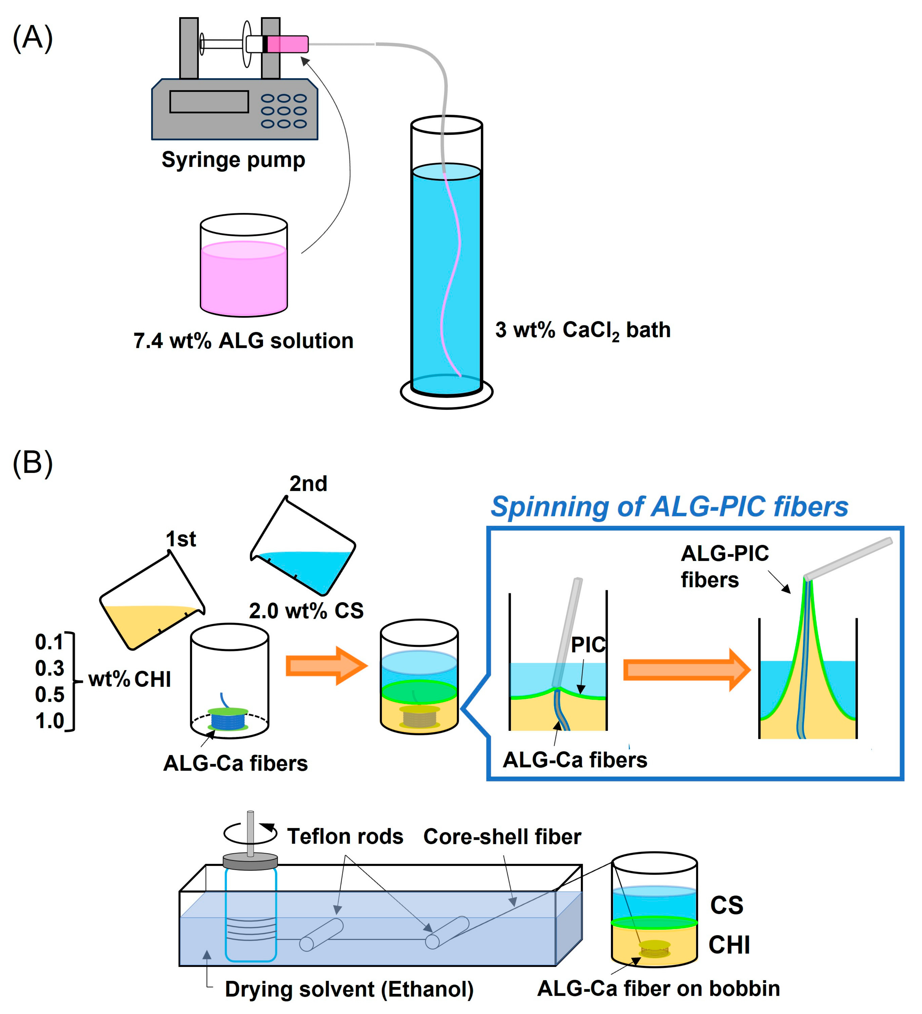
The preparation process of the ALG-Ca fibers is schematically shown in Figure 2A. First, 7.4 wt% of ALG solution was added to a syringe (2.5 mL, TERMO), and the syringe was equipped with a syringe pump (Legato 110, KDS). An amount of 3.0 wt% of CaCl2 aqueous solution (300 mL) was added to a graduated cylinder as a coagulation bath. The reason for using a graduated cylinder was to prevent fibers from touching each other at the bottom of the container before being solidified. The tube connected to the needle tip of the syringe was then immersed in the bath. The ALG solution was added to the bath at a constant rate (1000 μL/min) for spinning fibers. Afterward, the obtained fibers were dried at room temperature to obtain ALG-Ca fibers. For comparison, the fibers made of the PICs of CS and CHI (PIC fiber) were also prepared using the interface-spinning method [47,48] with several modifications. In order to form CS/CHI PIC interfaces, 2.0 wt% of CS solution (5.0 mL) was placed onto a predetermined concentration of CHI solution (5 mL) gently. The formed film at the interface was withdrawn, passed through an ethanol bath, and rolled up to give water-insoluble PICs fibers. Afterward, the obtained fibers were dried at room temperature.

2.3. Preparation of ALG-PIC Fibers

The ALG-PIC fibers were used for interface spinning, as shown in Figure 2B. The ALG-Ca fibers were rolled onto a 1.2 cm diameter bobbin. Then, 2.0 wt% of CS solution (5.0 mL) was gently placed onto a CHI solution (5 mL) to form PIC films at the interface. The ALG-Ca fibers were withdrawn and pulled up with the PIC films, and the coaxial fibers consisting of the ALG-Ca core fiber and the PIC coated layer were passed through an ethanol bath and rolled up. The obtained ALG-PIC fibers were dried at room temperature.
In order to observe the PIC layer on the ALG-PICs fiber, fluorescein-conjugated chondroitin sulfate C sodium salt (FL-CS) was used. The FL-CS was prepared in our laboratory [49]. CS (100 mg) was dissolved in a mixture of 10 mL of 1 M HCl and 5 mL of pyridine, fluoresceinamine (114 mg) was dissolved in a mixture of 2 mL of 1 M HCl and 2 mL of pyridine, and these solutions were mixed. At that time, the pH of the solution was adjusted to 4.75 by 12 M HCl. After that, 1-ethyl-3-(3-dimethylaminopropyl) carbodiimide (EDC, 390 mg) was dissolved in 2 mL of ultrapure water, and the solution was added to the mixed solution. The mixture was stirred for an hour at room temperature. Dialysis to ultrapure water was carried out on the obtained solution with cellulose dialysis tubes (Nihon Medical Science, Inc., Tokyo, Japan) Subsequently, cooled ethanol containing 1.25 wt% sodium acetate was added and centrifuged at 6000 rpm for 5 min. After washing with cooled ethanol, precipitates were dissolved in 10 mL of ultrapure water and dialyzed to ultrapure water again. The pH of the solution was adjusted to 7.4 with 0.1 M sodium hydroxide and the solution was freeze dried. An amount of 1 wt% of FL-CS was blended with CS, and PIC layers were prepared using the same procedure.

2.4. Preparation of FITC-Conjugated BSA (FITC-BSA)

Conjugation of FITC to BSA was performed using the previous method with several modifications [51]. When FITC was used, the reaction vessel was shielded from light. BSA (200 mg) was added to the carbonic acid buffer (pH 9.0, 100 mL), and FITC (5.0 mg) was dissolved in DMSO (5.0 mL). The FITC solution was dropwise to the BSA solution, and the mixture was stirred for 2 h at room temperature. After the reaction, the solution was dialyzed using a Visking tube (cutoff Mw. 12,000–14,000) in PBS (3 L, pH 7.4) for 3 days; fresh PBS was replaced every day. Afterward, the resulting solution was lyophilized, and FITC-BSA powder was obtained.

2.5. Fabrication of FITC-BSA-Loaded ALG-Ca Fibers and FITC-BSA-Loaded ALG-PIC Fibers

FITC-BSA-loaded ALG-Ca fibers were fabricated using a similar method to that used for the fabrication of ALG-Ca fibers. FITC-BSA (97 mg) was dissolved in 7.4 wt% of ALG solution (20 mL). The obtained solution was added to a syringe (2.5 mL, TERMO), and the syringe was equipped with a syringe pump (Legato 110, KDS). An amount of 3.0 wt% of CaCl2 aqueous solution (300 mL) was added to a graduated cylinder and the tube connected to the needle tip of the syringe was immersed in a bath. The ALG solution was added to the bath at a constant rate (1000 μL/min) for spinning fibers. Afterward, the obtained fibers were dried at room temperature with a light shade to obtain FITC-BSA-loaded ALG-Ca fibers. FITC-BSA-loaded ALG-PIC fibers were fabricated using a similar method to that used for the fabrication of ALG-PIC fibers but using the FITC-BSA-loaded ALG-Ca fibers instead of ALG-Ca fibers.

2.6. Characterization

The fibers were observed using an optical microscope (LV100, Nikon Corp., Tokyo, Japan) attached to an FL analyzer (LV-FLAN, Nikon Corp.). Diameters of the fibers were estimated using NIS Elements D, Nikon Corp. Fourier-transform infrared spectroscopy (FT-IR) measurements of the fibers were conducted (Nicolet 380; Thermo Fisher Scientific Inc., Waltham, MA, USA). The spectra were obtained using the single reflection attenuation total-reflection (ATR) method with a Quest ATR accessory (GS-10800, Specac Ltd., Orpington, UK). The spectra were recorded with a resolution of 1.929 cm−1 and baseline correction and ATR correction in the operating software were applied. The morphology and elemental composition of the fibers were evaluated using scanning electron microscopy and energy-dispersive X-ray spectroscopy (SEM and EDX, JSM-7001F; JEOL Ltd., Tokyo, Japan) with an acceleration voltage of 10 kV. In some cases, the specimens were coated with Pt–Pd using an ion-sputtering device (MC1000; Hitachi Ltd., Tokyo, Japan) to prevent charge-up.
The mechanical properties of the fibers were evaluated to calculate the tensile strength using a universal tester (Autograph AGS-500NJ; Shimadzu Corp., Kyoto, Japan). Initially, the diameter of the fiber required to calculate the tensile strength (MPa) that was obtained by dividing the test force (N) by the cross-sectional area of the sample was estimated by optical microscopic images. Afterward, the fibers were cut to 20 cm and placed in the apparatus while maintaining an initial gauge length of 10 cm. The stretching speed was set at 1 mm/min. The obtained stress–strain curves were analyzed using the Trapezium X software (Ver. 1.5.3., Shimadzu Corp., Kyoto, Japan). The test force (N) and the maximum tensile strengths (MPa) were expressed as the mean ± S.D.
The weight loss of the fibers was evaluated according to methods described in previous studies [28]. The fibers (1.0 m) were immersed in phosphate buffer saline (PBS, pH 7.4) and incubated at room temperature. The weight loss (%) was calculated using Equation (1).
Weight loss (%) = (WIWF)/WI × 100,
where WI is the initial weight of the fiber before immersion and WF is the final weight of the fiber after the immersion experiments followed by drying in air.

2.7. Release Experiments

FITC-BSA release from the FITC-BSA-loaded ALG-Ca fibers and the FITC-BSA-loaded ALG-PIC fibers was examined using a microplate reader (Varioskan Flash, Thermo Fisher Scientific Inc., Waltham, MA, USA). The fibers (10 cm) were wrapped around cylindrical stainless steel meshes and placed in wells of 96-well microtiter plates so as not to interfere with light irradiation and fluorescence detection of the wells. An amount of 200 μL of PBS (pH 7.4) was then added to each well. The microtiter plates were incubated at 37.5 °C and the fluorescence was measured at the predetermined times.

3. Results

3.1. Fabrication of ALG-PIC Fibers by Wet Spinning

ALG-Ca fibers were prepared using wet spinning techniques (Figure 2A). The fabrication was performed referring to Brzezińska’s report with several modifications [52]. The ALG solution injected from the syringe was gelled in the CaCl2 bath immediately, and transparent fibers were formed. The diameter of the obtained fibers was similar to that of a syringe needle (220 ± 30 μm). Afterward, the transparent fibers were washed and dried, and the ALG-Ca fibers were obtained (Figure 3A). The diameter of the ALG-Ca fibers was 170.1 ± 6.9 μm, which is thinner than that before drying (Figure S1). It indicated that the ALG-Ca fibers showed high swelling properties in an aqueous solution.
The ALG-PIC coaxial fibers were prepared by coating PIC layers composed of CS and CHI over the ALG-Ca fibers (Figure 2B). The fabrication was conducted in a similar way to the PIC fibers using interface-spinning techniques [47,48]. The PIC layer and ALG-Ca fiber were pulled up simultaneously. A hand-made apparatus was used for rolling up the obtained fibers. The winding rate was 1.3 cm/sec. To obtain ALG-PIC fibers with different thicknesses of PIC layer, four species of concentration of CHI solution (0.1, 0.3, 0.5, and 1.0 wt%) for interface spinning were used. With any concentration of CHI solution, the ALG-PICs fibers were successfully fabricated (denoted ALG-PIC-0.1wt%, ALG-PIC-0.3wt%, ALG-PIC-0.5wt%, and ALG-PIC-1.0wt%, respectively). Under optical microscopic observation, the surface of the ALG-Ca fiber was smooth (Figure 3A). However, the surface of the ALG-PICs fiber was rough, indicating that the difference in swelling ratio between ALG-Ca and the PIC layer caused some wrinkling with drying. Further, the diameters of each fiber were estimated from the optical microscopic images (Figure S1). In the case of using 0.1 wt% CHI solution, the diameter of ALG-PIC-0.1wt% was 143.0 ± 6.9 μm, which is thinner than that of the ALG-Ca fiber. It was suggested that the winding fibers were exposed to tension and elongated slightly. The viscosity of 0.1 wt% CHI solution is low, and therefore the PIC layer on the ALC-Ca core fiber was thin. Accordingly, the diameter of the fiber after coating the PIC layer was thinner than that before coating. When a high concentration of CHI solution was used, the layer thickness increased because the viscosity of the CHI solution increased. In particular, 1.0 wt% CHI solution provided ALG-PIC-1.0wt% fibers with 261.2 ± 36.8 μm of diameter. Thus, the use of a high concentration of CHI solution gave ALG-PIC fibers a thick layer of PIC.

3.2. Characterization and Evaluation of ALG-PIC Fibers

To confirm the PIC layer on the ALG-PICs fibers, fluorescein-conjugated chondroitin sulfate C sodium salt (FL-CS) was blended with CS for PIC formation and the obtained fibers were evaluated using fluorescence microscopy [49]. Figure S2A showed fluorescence microscopic images of ALG-PIC fibers with each concentration of CHI solution. When 0.1 wt% CHI solution was used, the fluorescence was weak, indicating that PIC was barely coated. In the case of high concentrations of CHI solutions, each fiber showed strong fluorescence. This tendency was consistent with the results for the diameter (Figure S1): it indicated that the diameter of the PIC layer increased with increasing concentration of CHI solution. Furthermore, the ALG-PIC fibers with 0.3 and 0.5 wt% of CHI solution were darker in the center and the edge of the fibers showed strong fluorescence. This indicated that the light for the excitation path through the PIC layer at the edge of the fiber was longer than that at the center of the fiber, as shown in Figure S2B. Accordingly, a thicker layer of PIC was coated on the ALG-Ca fibers when a higher concentration of CHI solution was used.
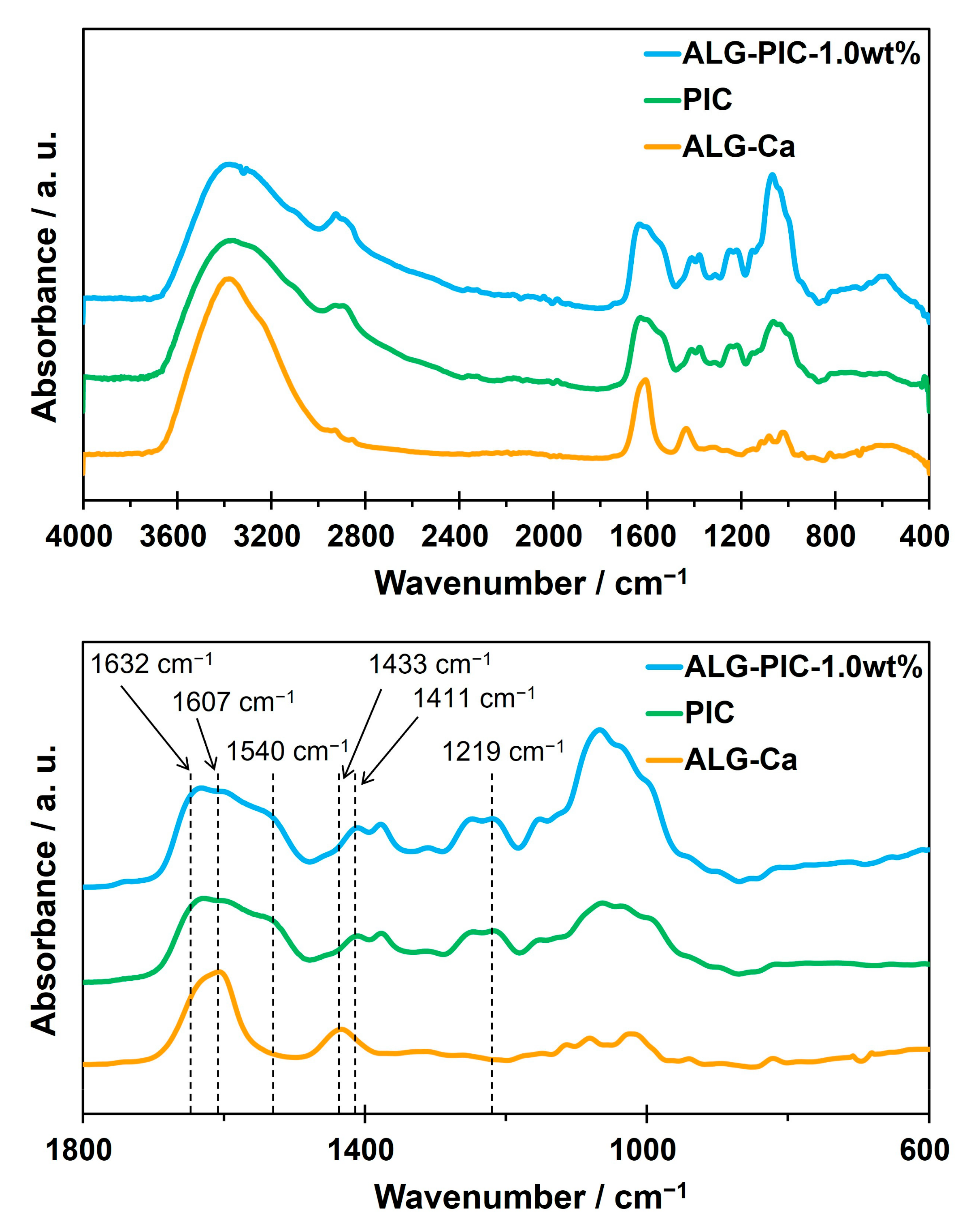
Figure 4 shows the FT-IR spectra of ALG-Ca fibers, ALG-PIC-1.0wt% fibers, and PIC fibers. The PIC fibers were prepared by wet spinning with several modifications [42,43]. Peaks at 1607 cm−1 and 1433 cm−1 originating from COO in ALG appeared in the spectrum of ALG-Ca fibers. On the other hand, ALG-PIC-1.0wt% fiber showed peaks originating from functional groups in CS: two peaks at 1632 cm−1 and 1411 cm−1 (COO), at 1219 cm−1 (SO3), and a peak at 1540 cm−1 originating from NH3+ in CHI. These peaks also appeared in the FT-IR spectrum of the PIC fiber, and both of them supported electrostatic interactions between CS and CHI [27,28]. This is because the penetration depth of the IR by attenuated total reflection (ATR) is a few micrometers at IR wavelengths, which is much smaller than the PIC layer of the ALG-PIC fiber. Therefore, only the surface PIC layer was detected, and the same spectrum as the PIC fiber was obtained for the ALG-PIC fibers.
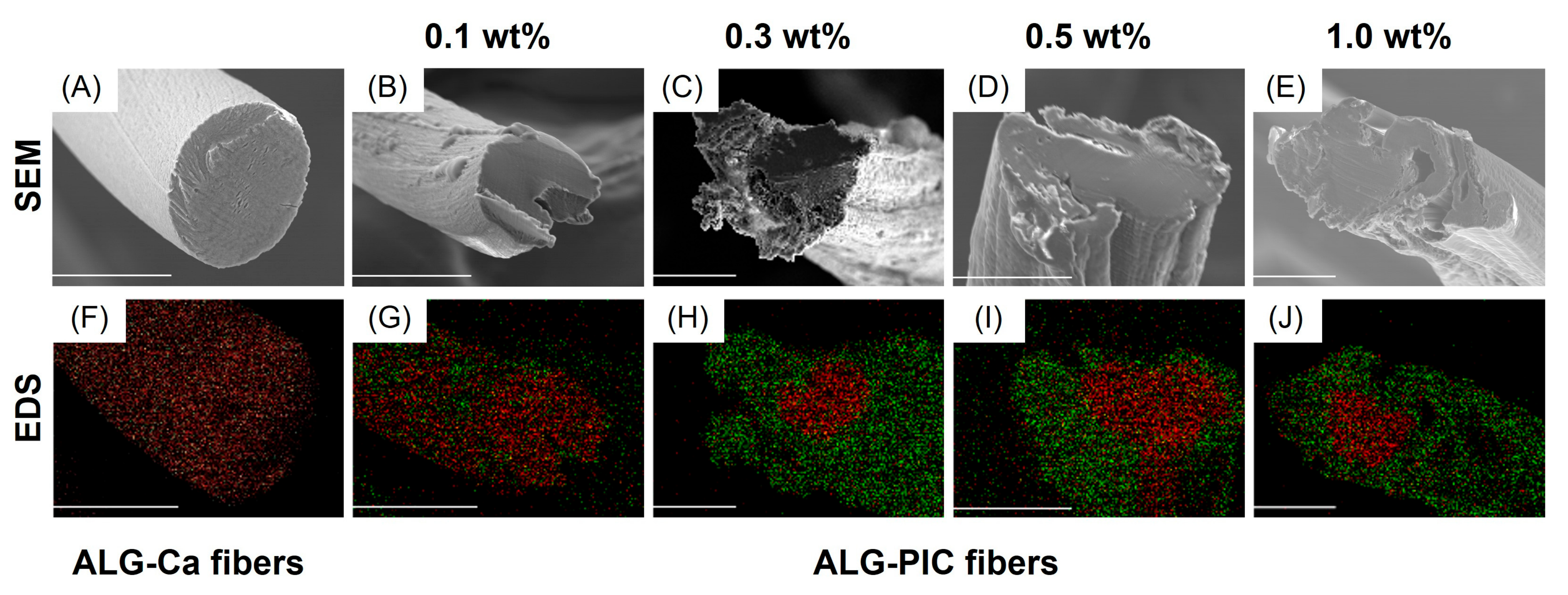
SEM observation and EDS measurements of each fiber were also performed to evaluate their microscopic morphologies and elemental compositions (Figure 5). In the EDS mapping, Ca element (red) and S element (green) were used to observe ALG-Ca fibers and PIC layers, respectively. The SEM image of a cross-section of the ALG-Ca fiber showed smooth and dense structures without cracks and pores. Further, the presence of Ca in the whole region of the ALG-Ca fiber was confirmed by EDS mapping. In the case of ALG-PIC-0.1wt% fiber, the fiber was distorted due to the tension created by the winding fibers in the PIC coating process. EDS mapping showed that Ca elements were detected not only in the core region of the cross-section but also on the outer surface of the fibers, indicating that PICs were slightly coated on the ALG-Ca fiber. On the contrary, EDS mappings of ALG-PIC-0.3wt%, ALG-PIC-0.5wt%, and ALG-PIC-1.0wt% showed that PIC layers were fully coated on the ALG-Ca fiber. These results were consistent with the observation by fluorescence microscopy (Figure S2). Thus, the diameter of fibers increases with the coatings of PICs, and the thickness of the PIC coating layer can be adjusted by changing the concentration of CHI solution. Unfortunately, accurate measurement of the thickness of the PIC layers was hardly achieved because of the inhomogeneous morphology of the core and shell regions of the fibers in the EDS mappings.
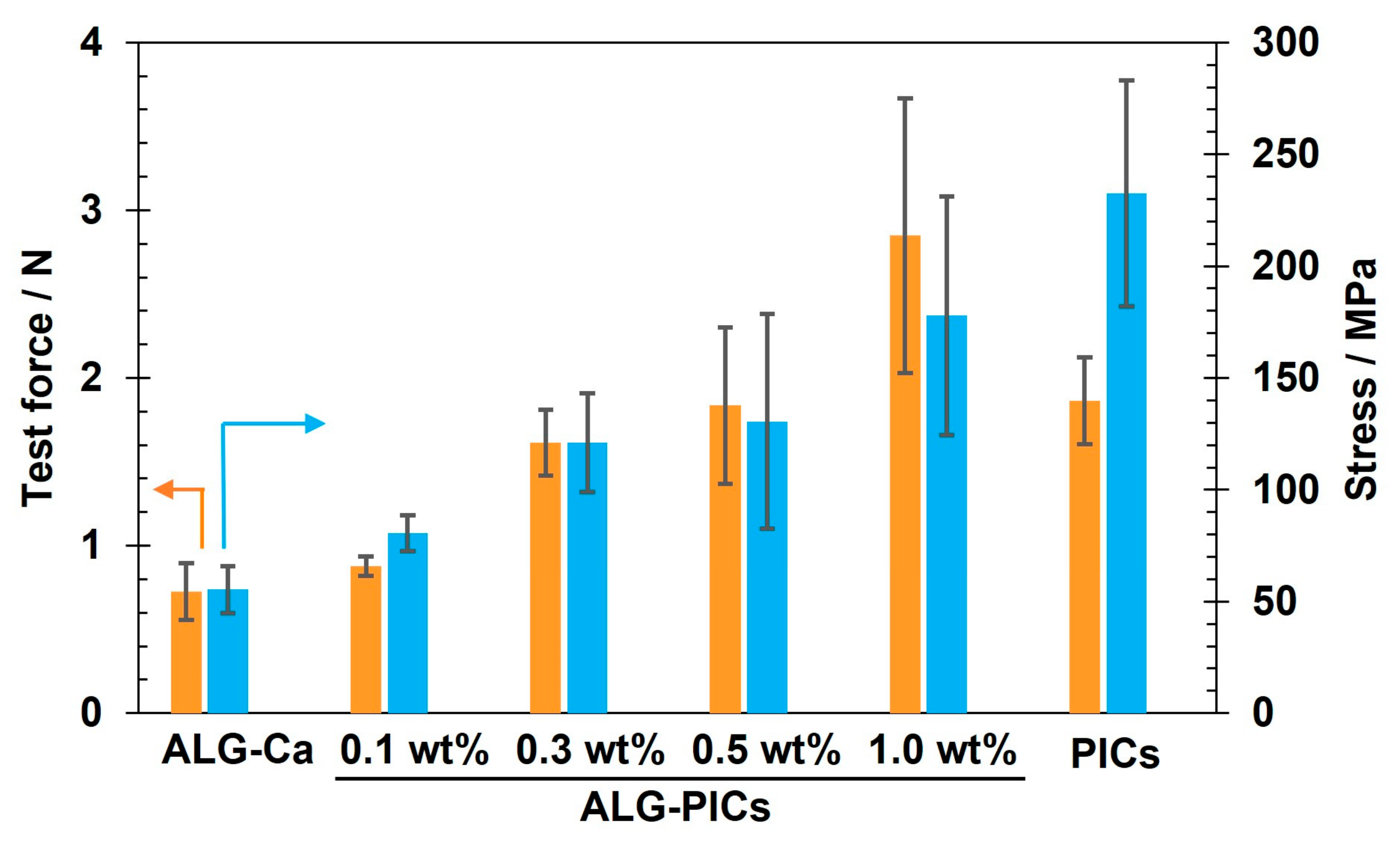
To evaluate the mechanical properties of the fibers, tensile tests of ALG-Ca fibers, PIC fibers, and each ALG-PIC fiber were conducted (Figure 6). In a comparison of ALG-Ca fibers and PIC fibers, the ALG-Ca fibers exhibited low strength and were easily stretched, but the PIC fiber was high in strength and difficult to stretch. On the other hand, it was clearly demonstrated that the ALG-PIC fibers exhibited higher strength than the ALG-Ca fibers. Further, the strength of the ALG-PIC fibers increased with an increasing number of PIC coatings, whereas the strain of the ALG-PIC fibers decreased. This is because the ratio of PICs to the fiber was increased, and therefore the strength of the fibers was improved. In a comparison of the ALG-PIC-1.0wt% fiber and the PIC fiber, the ALG-PIC-1.0wt% fiber showed larger test force, whereas the PIC fiber showed higher strength. ALG-PIC-1.0wt% contained ALG-Ca core, which had lower mechanical strength and higher elongation properties than PIC. This is because the diameter of ALG-PIC-1.0wt% was larger than that of the PIC fiber, and the average strength per cross-sectional area decreased due to the lower strength of ALG-Ca. From the above, although the strength of ALG-Ca fiber was low, the strength was improved by coating with PIC. Accordingly, PIC coatings on ALG-PIC fibers were useful in improving the mechanical properties of the fibers.
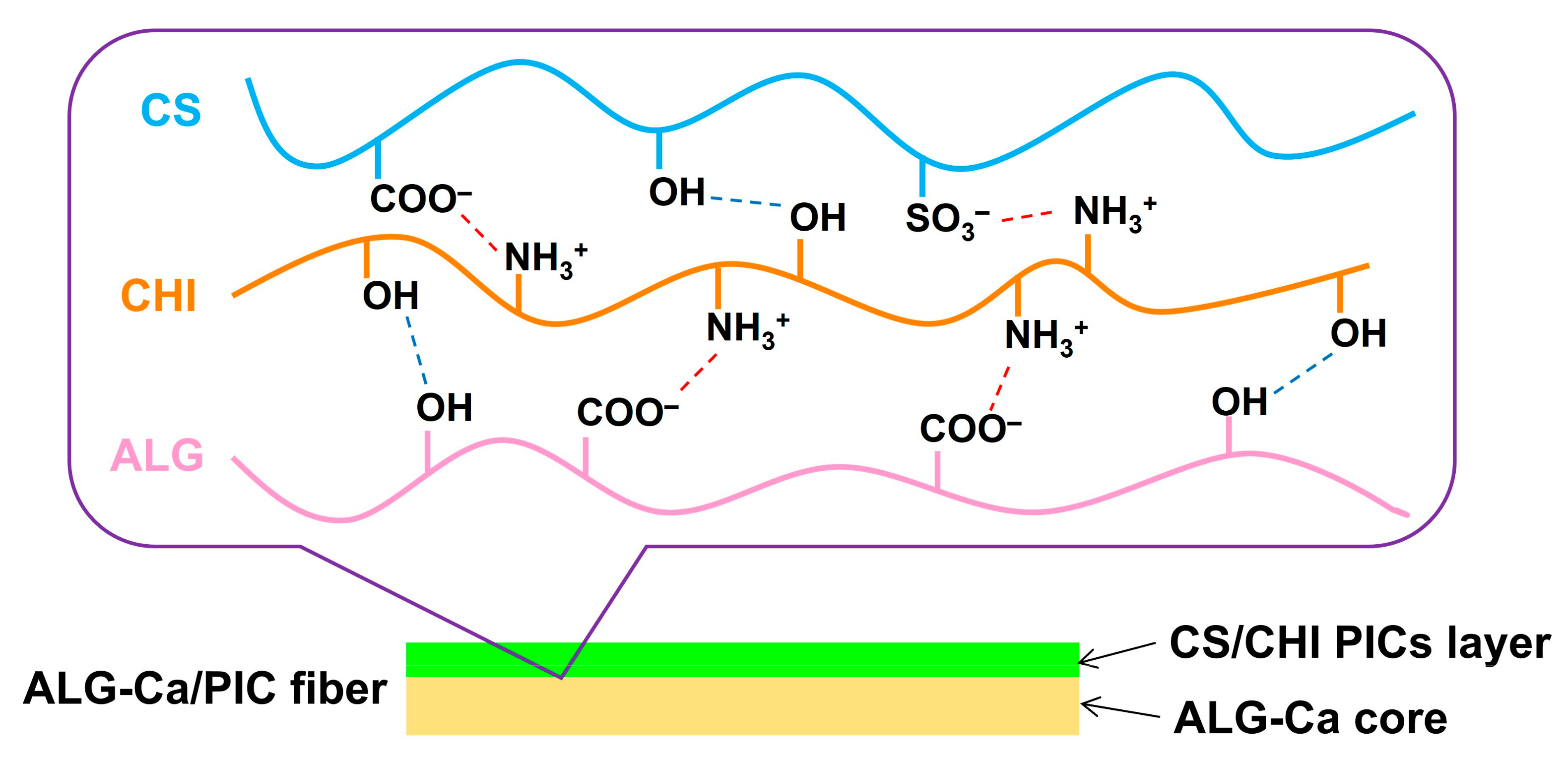
To clarify the stability of each fiber in an aqueous solution, the weight loss of each fiber after immersion in phosphate buffer saline (PBS, pH 7.4) was evaluated (Figure 7). The ALG-Ca fibers dissolved and lost their shape after immersion in PBS for 1 day. This is because the interaction between ALG and Ca2+ was relaxed by water, and Ca2+ was replaced with monovalent ions such as Na+ and K+ in PBS, resulting in the solubilization of ALG-Ca fibers [53]. In the case of the ALG-PIC-0.1wt%, about 7% of the weight remained after immersion for 1 day. After immersion for 3 days, the fiber lost its shape and dissolved in PBS. When a 0.1 wt% CHI solution was used, a small amount of PIC was present on the fiber surface and thus remained longer than ALG-Ca fiber due to the greater stability of PIC in PBS than ALG-Ca, but the effect of the PIC was minimal. When 0.3, 0.5, and 1.0 wt% ALG-PIC fibers were used, the weight loss was low after 1-day of immersion, indicating that the amount of PIC coating on the fibers was large, and ALG was immobilized by electrostatic interaction and hydrogen bonding with CHI of PICs (Figure 8). The weight loss gradually increased with increasing immersion time, and ALG-PIC-1.0% had the lowest weight loss in the fabricated fibers, indicating that the fiber had the highest amount of PIC coating. ALG-PIC-0.3wt% and -0.5wt% showed smaller remaining weights for 5 days to 7 days compared to ALG-PIC-1.0wt%. The final residual weight was 27.5% with the ALG-PIC-0.3wt% fiber, 30.1% with the ALG-PIC-0.5wt% fiber, and 39.8% with the ALG-PIC-1.0wt% fiber, respectively. This is because ALG-Ca was less stable than the PICs and showed a larger weight loss. Thus, PIC coatings improve the stability of ALG-Ca fibers, and this approach is promising for improving the mechanical stability of other types of fibers.

3.3. Utilization of ALG-PIC Fibers as a DDS Carrier

The ALG-PIC fibers exhibited swellability and stability in an aqueous solution, and thus they can be applied as a DDS carrier. Previously, we have reported that polysaccharide composite films made of PICs of CS and CHI exhibit drug loading and sustained-release properties [30]. We thought that PIC-coated fibers could also exhibit sustained drug release ability. Here, the PIC layer is expected to suppress the burst release of the drug to control its permeation rate. In this experiment, FITC-BSA was used as a model drug and loaded onto the ALG-Ca core fiber to evaluate the release behavior.
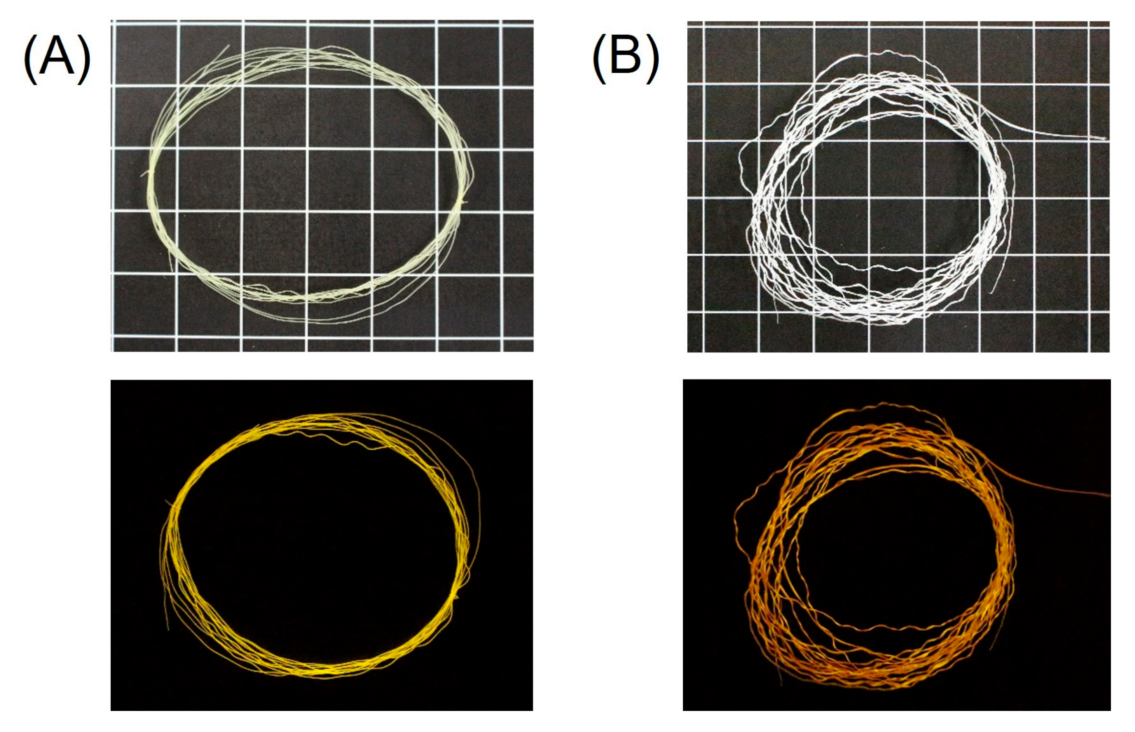
FITC-BSA-loaded ALG-Ca fibers and the corresponding PIC-coated fibers were fabricated. The FITC-BSA was obtained by the reaction of BSA and FITC, and the fluorescence spectrum showed that about 1.8 moles of FITC were conjugated per mole of BSA. A mixed solution of FITC-BSA and ALG was injected into an CaCl2 bath to obtain FITC-BSA-loaded ALG-Ca fibers. The obtained fibers possessed 96.0 μg/m (7.3 μg/mg) of FITC-BSA. The fibers were colored pale yellow and showed fluorescence with irradiation of UV light (Figure 9A). Afterward, the PIC layer was coated on the fibers in the same manner as aforementioned using CHI solutions of various concentrations to obtain FITC-BSA-loaded ALG-PIC fibers. The appearance of the fibers (Figure 9B) was similar to that of the ALG-PIC fibers. Under a UV light, the color of the FITC-BSA-loaded ALG-PIC fibers looked slightly different from that of the FITC-BSA-loaded ALG-Ca fibers. This was probably due to the effect of scattering originating from the surface roughness.
The release behavior of FITC-BSA of FITC-BSA-loaded fibers in PBS was investigated. For the case of the FITC-BSA-loaded ALG-Ca fiber, the release ratio reached 36% in 4 h and then remained constant (Figure 10A). This is because FITC-BSA might interact with ALG by intermolecular interactions such as hydrogen bonding and electrostatic interactions. FITC-BSA-loaded ALG-PIC fibers prepared using 0.1 wt% CHI showed FITC-BSA release with almost the same behavior, indicating that the PIC layer is too thin to suppress the FITC-BSA release. In the case of using higher concentrations of CHI solution, the release ratios of FITC-BSA decreased. The release ratio of FITC-BSA-loaded ALG-PIC fibers prepared using 0.3, 0.5, and 1.0 wt% of CHI showed 31%, 22%, and 12% in 1 day, respectively. Further, focusing on the initial burst release rate, ALG-Ca was the fastest at 0.91 μg/min. Notably, FITC-BSA-loaded ALG-PIC fibers with 0.1 wt% CHI were much slower at 0.36 μg/min than ALG-Ca fiber. This indicated that the initial burst release was greatly suppressed by a thin PIC layer on ALG-Ca fiber (Figure 10B). As the cause of these results, the surface charge of ALG-PIC was considered. It was reported that surface charge of the drug carriers can affect the interaction with drugs and their loading/releasing properties, through electrostatic [54] and/or electro-induced [55] mechanisms. The zeta potential of PICs consisting of chondroitin sulfate C (CS) and CHI in PBS (pH 7.4) was −9 mV [56], indicating that the PIC layers were slightly negatively charged in PBS. On the other hand, the pI of BSA and its derivatives is 5.0–5.5, suggesting that BSA is also negatively charged in PBS at pH 7.4. Accordingly, it was indicated that electrostatic repulsions between FITC-BSA and the PIC layers occurred when FITC-BSA that was released from the ALG-Ca core crossed the PIC layers to be released to PBS. In the case of fibers prepared using 0.3 wt% CHI or more, the initial burst velocity was about 0.10 μg/min. These results were consistent with the tendency of PIC thickness, with thicker PICs suppressing the initial burst. Accordingly, the coatings with PIC on ALG-Ca fibers inhibited the initial burst release of the FITC-BSA and achieved sustained release.

4. Conclusions

PIC coating layers consisting of CS and CHI on ALG-Ca fibers prepared by solution spinning was demonstrated. The thickness of the PIC layers on the resulting ALG-PIC fibers was controllable: it increased with increasing concentration of CHI solution used to form the PIC layer. The PIC coatings improved the mechanical strength of the fibers. In addition, the solubility in PBS of the fibers was greatly suppressed by the PIC coatings. These results indicate the existence of electrostatic interactions and hydrogen bonds among ALG-Ca and CS and CHI of PICs. Furthermore, FITC-BSA-loaded ALG-Ca fibers and FITC-BSA-loaded ALG-PIC fibers were successfully prepared. Thicker PIC layers slowed the release of FITC-BSA from the fibers and suppressed the initial burst release. Accordingly, the PIC coatings of the fibers improved the strength and durability of the core fibers and provided sustained drug release, and such fibers can be utilized as practical drug carriers. Because fibers can be used not only as the fiber morphology but also as materials in other forms created by bundling or weaving, they can be used as drug carriers in various internal and extracorporeal environments. The present approach can be utilized for other proteins such as real protein drugs. In such cases, the loading efficiency and the effect of the PIC coating layers on the release ability might be different depending on the size and surface charges of the proteins. A series of systematic investigations along these lines is one of the future tasks required to bring this system closer to practical use.

Supplementary Materials

The following supporting information can be downloaded at: https://www.mdpi.com/article/10.3390/app13148053/s1, Figure S1: Diameters of ALG-Ca fibers and ALG-PIC fibers with each concentration of CHI solutions; Figure S2: Fluorescence microscopic images of ALG-PIC fibers and schematic image of irradiation and excitation light through the fibers.

Author Contributions

Conceptualization, M.H.; methodology, M.H., K.I. and Y.Y.; investigation, H.M.; data curation, T.S., H.M. and M.H.; writing—original draft preparation, T.S.; writing—review and editing, M.H.; visualization, T.S.; supervision, M.H.; project administration, M.H.; funding acquisition, M.H. All authors have read and agreed to the published version of the manuscript.

Funding

This research was funded by JSPS KAKENHI, grant number JP25410178 and JP16K05799.

Informed Consent Statement

Not applicable.

Data Availability Statement

Not applicable.

Acknowledgments

We also thank Hidenori Otsuka (Tokyo University of Science) for allowing us to conduct the analysis of the release ratio of FITC-BSA using a microplate reader.

Conflicts of Interest

The authors declare no conflict of interest.

References

  1. Silva, A.C.Q.; Silvestre, A.J.D.; Vilela, C.; Freire, C.S.R. Natural Polymers-Based Materials: A Contribution to a Greener Future. Molecules 2022, 27, 94. [Google Scholar] [CrossRef] [PubMed]
  2. Müller, K.; Zollfrank, C.; Schmid, M. Natural Polymers from Biomass Resources as Feedstocks for Thermoplastic Materials. Macromol. Mater. Eng. 2019, 304, 1800760. [Google Scholar] [CrossRef]
  3. Liu, Z.; Jiao, Y.; Wang, Y.; Zhou, C.; Zhang, Z. Polysaccharides-based nanoparticles as drug delivery systems. Adv. Drug Deliv. Rev. 2008, 60, 1650–1662. [Google Scholar] [CrossRef] [PubMed]
  4. García-González, C.A.; Alnaief, M.; Smirnova, I. Polysaccharide-based aerogels—Promising biodegradable carriers for drug delivery systems. Carbohydr. Polym. 2011, 86, 1425–1438. [Google Scholar] [CrossRef]
  5. Prasher, P.; Sharma, M.; Mehta, M.; Satija, S.; Aljabali, A.A.; Tambuwala, M.M.; Anand, K.; Sharma, N.; Dureja, H.; Jha, N.K.; et al. Current-status and applications of polysaccharides in drug delivery systems. Colloids Interface Sci. Commun. 2021, 42, 100418. [Google Scholar] [CrossRef]
  6. Zhang, M.; Ma, H.; Wang, X.; Yu, B.; Cong, H.; Shen, Y. Polysaccharide-based nanocarriers for efficient transvascular drug delivery. J. Control. Release 2023, 354, 167–187. [Google Scholar] [CrossRef]
  7. Zhu, T.; Mao, J.; Cheng, Y.; Liu, H.; Lv, L.; Ge, M.; Li, S.; Huang, J.; Chen, Z.; Li, H.; et al. Recent Progress of Polysaccharide-Based Hydrogel Interfaces for Wound Healing and Tissue Engineering. Adv. Mater. Interfaces 2019, 6, 1900761. [Google Scholar] [CrossRef] [Green Version]
  8. Yang, J.; Wang, S. Polysaccharide-Based Multifunctional Hydrogel Bio-Adhesives for Wound Healing: A Review. Gels 2023, 9, 138. [Google Scholar] [CrossRef]
  9. Croisier, F.; Atanasova, G.; Poumay, Y.; Jérôme, C. Polysaccharide-Coated PCL Nanofi bers for Wound Dressing Applications. Adv. Healthc. Mater. 2014, 3, 2032–2039. [Google Scholar] [CrossRef]
  10. Miraftaba, M.; Qiao, Q.; Kennedy, J.F.; Anand, S.C.; Groocock, M.R. Fibres for wound dressings based on mixed carbohydrate polymer fibres. Carbohydr. Polym. 2003, 86, 225–231. [Google Scholar] [CrossRef]
  11. Ju, S.; Zhang, F.; Duan, J.; Jiang, J. Characterization of bacterial cellulose composite films incorporated with bulk chitosan and chitosan nanoparticles: A comparative study. Carbohydr. Polym. 2020, 237, 116167. [Google Scholar] [CrossRef] [PubMed]
  12. Saeedi, M.; Vahidi, O.; Moghbeli, M.R.; Ahmadi, S.; Asadnia, M.; Akhavan, O.; Seidi, F.; Rabiee, M.; Saeb, M.R.; Webster, T.J.; et al. Customizing nano-chitosan for sustainable drug delivery. J. Control. Release 2022, 350, 175–192. [Google Scholar] [CrossRef]
  13. Bazmandeh, A.Z.; Mirzaei, E.; Fadaie, M.; Shirian, S.; Ghasemi, Y. Dual spinneret electrospun nanofibrous/gel structure of chitosan-gelatin/chitosan-hyaluronic acid as a wound dressing: In-vitro and in-vivo studies. Int. J. Biol. Macromol. 2020, 162, 359–373. [Google Scholar] [CrossRef] [PubMed]
  14. Mazaheri, M.; Akhavan, O.; Simchi, A. Flexible bactericidal graphene oxide–chitosan layers for stem cell proliferation. Appl. Surf. Sci. 2014, 301, 456–462. [Google Scholar] [CrossRef]
  15. Yousefiasl, S.; Manoochehri, H.; Makvandi, P.; Afshar, S.; Salahinejad, E.; Khosraviyan, P.; Saidijam, M.; Asl, S.S.; Sharif, E. Chitosan/alginate bionanocomposites adorned with mesoporous silica nanoparticles for bone tissue engineering. J. Nanostruct. Chem. 2023, 13, 389–403. [Google Scholar] [CrossRef]
  16. Rahighi, R.; Panahi, M.; Akhavan, O.; Mansoorianfar, M. Pressure-engineered electrophoretic deposition for gentamicin loading within osteoblast-specific cellulose nanofiber scaffolds. Mater. Chem. Phys. 2021, 272, 125018. [Google Scholar] [CrossRef]
  17. Alvarez-Lorenzo, C.; Blanco-Fernandez, B.; Puga, A.M.; Concheiro, A. Crosslinked ionic polysaccharides for stimuli-sensitive drug delivery. Adv. Drug Deliv. Rev. 2013, 65, 1148–1171. [Google Scholar] [CrossRef]
  18. Dumitriu, S. Chornet, Inclusion and release of proteins from polysaccharide-based polyion complexes. Adv. Drug Deliv. Rev. 1998, 31, 223–246. [Google Scholar] [CrossRef]
  19. Sun, X.; Liu, C.; Omer, A.M.; Yang, L.; Ouyang, X. Dual-layered pH-sensitive alginate/chitosan/kappa-carrageenan microbeads for colon-targeted release of 5-fluorouracil. Macromolecules 2019, 132, 487–494. [Google Scholar] [CrossRef]
  20. Grasdalen, H.; Larsen, B.; Smidsrød, O. A p.m.r. study of the composition and sequence of uronate residues in alginates. Carbohydr. Res. 1979, 68, 23–31. [Google Scholar] [CrossRef]
  21. Hecht, H.; Srebnik, S. Structural Characterization of Sodium Alginate and Calcium Alginate. Biomacromolecules 2016, 17, 2160–2167. [Google Scholar] [CrossRef]
  22. Kumar, M.N.V.R. A review of chitin and chitosan applications. React. Funct. Polym. 2000, 46, 1–27. [Google Scholar] [CrossRef]
  23. Rinaudo, M. Chitin and chitosan: Properties and applications. Prog. Polym. Sci. 2006, 31, 603–632. [Google Scholar] [CrossRef]
  24. Alimirzaei, F.; Vasheghani-Farahani, E.; Ghiaseddin, A.; Soleimani, M.; Pouri; Zeinab, N. pH-Sensitive Chitosan Hydrogel with Instant Gelation for Myocardial Regeneration. J. Tissue Sci. Eng. 2017, 8, 1000212. [Google Scholar]
  25. Denuziere, A.; Ferrier, D.; Domard, A. Chitosan-chondroitin sulfate and chitosan-hyaluronate polyelectrolyte complexes. Physico-chemical aspects. Carbohydr. Polym. 1996, 29, 317–323. [Google Scholar] [CrossRef]
  26. Hamman, J.H. Chitosan Based Polyelectrolyte Complexes as Potential Carrier Materials in Drug Delivery Systems. Mar. Drugs 2010, 8, 1305–1322. [Google Scholar] [CrossRef] [Green Version]
  27. Hashizume, M.; Kobayashi, H.; Ohashi, M. Preparation of Free-Standing Films of Natural Polysaccharides Using Hot Press Technique and Their Surface Functionalization with Biomimetic Apatite. Colloids Surf. B Biointerfaces 2011, 88, 534–538. [Google Scholar] [CrossRef] [PubMed]
  28. Hashizume, M.; Ohashi, M.; Kobayashi, H.; Tsuji, Y.; Iijima, K. Free-standing Polysaccharide Composite Films: Improved Preparation and Physical Properties. Colloids Surf. A Physicochem. Eng. Asp. 2015, 484, 18–24. [Google Scholar] [CrossRef]
  29. Iijima, K.; Tsuji, Y.; Kuriki, I.; Kakimoto, A.; Nikaido, Y.; Ninomiya, R.; Iyoda, T.; Fukai, F.; Hashizume, M. Control of Cell Adhesion and Proliferation Utilizing Polysaccharide Composite Film Scaffolds. Colloids Surf. B Biointerfaces 2017, 160, 228–237. [Google Scholar] [CrossRef] [PubMed]
  30. Hashizume, M.; Murata, Y.; Iijima, K.; Shibata, T. Drug Loading and Release Behaviors of Freestanding Polysaccharide Composite Films. Polym. J. 2016, 48, 545–550. [Google Scholar] [CrossRef]
  31. Iijima, K.; Kimura, T.; Sato, R.; Takahashi, T.; Hashizume, M. Kinetic Analysis of Molecular Permeabilities of Free-standing Polysaccharide Composite Films. Macromol. Chem. Phys. 2017, 218, 1600391. [Google Scholar] [CrossRef]
  32. Sagawa, T.; Sakakibara, M.; Iijima, K.; Yataka, Y.; Hashizume, M. Preparation and physical properties of free-standing films made of polyion complexes of carboxymethylated hyaluronic acid and chitosan. Polymer 2022, 253, 125033. [Google Scholar] [CrossRef]
  33. Sagawa, T.; Nikaido, Y.; Iijima, K.; Sakaguchi, M.; Yataka, Y.; Hashizume, M. Preparation of Mechanically Anisotropic Polysaccharide Composite Films Using Roll-Press Techniques. ACS Omega 2023, 8, 5607–5616. [Google Scholar] [CrossRef] [PubMed]
  34. Decher, G. Fuzzy Nanoassemblies: Toward Layered Polymeric Multicomposites. Science 1997, 277, 1232–1237. [Google Scholar] [CrossRef]
  35. Decher, G.; Schlenoff, J.B. (Eds.) Multilayer Thin Films, 2nd ed.; Wiley-VCH: Weinheim, Germany, 2012. [Google Scholar]
  36. Moreira, J.; Vale, A.C.; Pires, R.A.; Botelho, G.; Reis, R.L.; Alves, N.M. Spin-Coated Polysaccharide-Based Multilayered Freestanding Films with Adhesive and Bioactive Moieties. Molecules 2020, 25, 840. [Google Scholar] [CrossRef] [Green Version]
  37. Tamura, H.; Tsuruta, Y.; Itoyama, K.; Worakitkanchanakul, W.; Rujiravanit, R.; Tokura, S. Preparation of chitosan filament applying new coagulation system. Carbohydr. Polym. 2004, 56, 205–211. [Google Scholar] [CrossRef]
  38. Perrin, N.; Mohammadkhani, G.; Homayouni, M.F.; Delattre, C.; Zamani, A. Biocompatible fibers from fungal and shrimp chitosans for suture application. Curr. Opin. Biotechnol. 2022, 4, 530–536. [Google Scholar] [CrossRef]
  39. Onoe, H.; Okitsu, T.; Itou, A.; Kato-Negishi, M.; Gojo, R.; Kiriya, D.; Sato, K.; Miura, S.; Iwanaga, S.; Kuribayashi-Shigetomi, K.; et al. Metre-long cell-laden microfibres exhibit tissue morphologies and functions. Nat. Matter. 2013, 12, 584–590. [Google Scholar] [CrossRef]
  40. Zhang, H.; Cheng, J.; Ao, Q. Preparation of Alginate-Based Biomaterials and Their Applications in Biomedicine. Mar. Drugs 2021, 19, 264. [Google Scholar] [CrossRef]
  41. Desai, K.; Kit, K.; Li, J.; Zivanovic, S. Morphological and Surface Properties of Electrospun Chitosan Nanofibers. Biomacromolecules 2008, 9, 1000–1006. [Google Scholar] [CrossRef]
  42. Okada, T.; Nobunaga, Y.; Konishi, T.; Yoshioka, T.; Hayakawa, S.; Lopes, M.A.; Miyazaki, T. Preparation of chitosan-hydroxyapatite composite mono-fiber using coagulation method and their mechanical properties. Carbohydr. Polym. 2017, 175, 355–360. [Google Scholar] [CrossRef] [PubMed]
  43. Hachisu, M.; Ohkawa, K.; Yamamoto, H. Preparation of Silk-Like Fibers Designed by Self-Assembled Ionic Polypeptides. Macromol. Biosci. 2003, 3, 92–99. [Google Scholar] [CrossRef]
  44. Yamamoto, H.; Senoo, Y. Polyion complex fiber and capsule formed by selfassembly of chitosan and gellan at solution interfaces. Macromol. Chem. Phys. 2000, 201, 84–92. [Google Scholar] [CrossRef]
  45. Chen, W.-B.; Wang, L.-F.; Chen, J.-S.; Fan, S.-Y. Characterization of polyelectrolyte complexes between chondroitin sulfate and chitosan in the solid state. J. Biomed. Mater. Res. A 2005, 75, 128–137. [Google Scholar] [CrossRef]
  46. Huang, H.; Trentle, M.; Liu, Z.; Xiang, K.; Higgins, W.; Wang, Y.; Xue, B.; Yang, S. Polymer Complex Fiber: Property, Functionality, and Applications. ACS Appl. Mater. Interfaces 2023, 15, 7639–7662. [Google Scholar] [CrossRef] [PubMed]
  47. Iijima, K.; Yuyama, K.; Asaine, K.; Irie, K.; Hashizume, M. Preparation of Chondroitin Sulfate/Chitosan Composite Fibers by Spinning from Aqueous Solution Interfaces. Kobunshi Ronbunshu 2014, 71, 11–16. [Google Scholar] [CrossRef]
  48. Iijima, K.; Hashizume, M. Application of Polysaccharides as Structural Materials. Trends Glycosci. Glycotechnol. 2015, 27, 67–79. [Google Scholar] [CrossRef] [Green Version]
  49. Iijima, K.; Ohyama, S.; Yuyama, K.; Shono, A.; Hashizume, M. Selective fabrication of hollow and solid polysaccharide composite fibers using a microfluidic device by controlling polyion complex formation. Polym. J. 2018, 50, 1187–1198. [Google Scholar] [CrossRef] [Green Version]
  50. Iijima, K.; Ichikawa, S.; Ishikawa, S.; Matsukuma, D.; Yataka, Y.; Otsuka, H.; Hashizume, M. Preparation of Cell-Paved and -Incorporated Polysaccharide Hollow Fibers Using a Microfluidic Device. ACS Biomater. Sci. Eng. 2019, 5, 5688–5697. [Google Scholar] [CrossRef]
  51. Hermanson, G.T. Bioconjugate Techniques, 2nd ed.; Elsevier: Amsterdam, The Netherlands, 2008. [Google Scholar]
  52. Brzezińska, M.; Szparaga, G. The Effect of Sodium Alginate Concentration on the Rheological Parameters of Spinning Solutions. Autex Res. J. 2015, 15, 123–126. [Google Scholar] [CrossRef] [Green Version]
  53. Plazinski, W. Conformational properties of acidic oligo- and disaccharides and their ability to bind calcium: A molecular modeling study. Carbohydr. Res. 2012, 357, 111–117. [Google Scholar] [CrossRef] [PubMed]
  54. Ho, E.; Deng, Y.; Akbar, D.; Da, K.; Létourneau, M.; Morshead, C.M.; Chatenet, D.; Shoichet, M.S. Tunable Surface Charge Enables the Electrostatic Adsorption-Controlled Release of Neuroprotective Peptides from a Hydrogel−Nanoparticle Drug Delivery System. ACS. Appl. Mater. Interfaces 2023, 15, 91–105. [Google Scholar] [CrossRef]
  55. Khosravikia, M.; Rahbar-Kelishami, A. A simulation study of an applied approach to enhance drug recovery through electromembrane extraction. J. Mol. Liq. 2022, 3585, 119210. [Google Scholar] [CrossRef]
  56. Sagawa, T.; Oishi, M.; Yataka, Y.; Sato, R.; Iijima, K.; Hashizume, M. Control of the molecular permeability of polysaccharide composite films utilizing a molecular imprinting approach. Polym. J. 2022, 54, 571–579. [Google Scholar] [CrossRef]
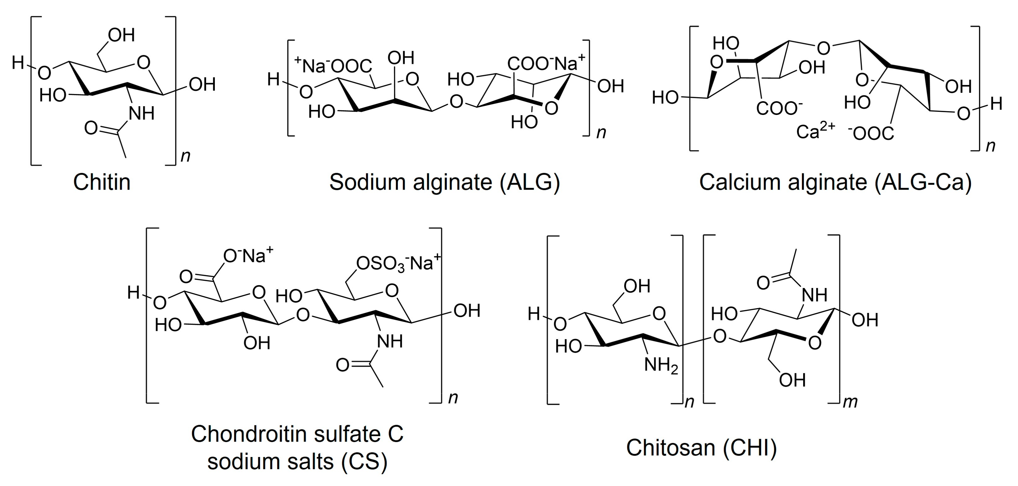
Figure 1. Chemical structures of chitin, sodium alginate (ALG), calcium alginate (ALG-Ca), chondroitin sulfate C sodium salts (CS), and chitosan (CHI). For ALG and ALG-Ca, one of the representative structures is shown.
Applsci 13 08053 g001
Figure 2. Schematic illustration of the fabrication of (A) ALG-Ca fiber and (B) ALG-PIC fibers.
Applsci 13 08053 g002
Figure 3. Photographs (top) and optical microscopic images (bottom) of (A) ALG-Ca fibers and (B) ALG-PICs fibers. (Grid: 0.5 × 0.5 cm2).
Applsci 13 08053 g003
Figure 4. FT-IR spectra of ALG-PICs-1.0wt% fiber, PIC fiber, and ALG-Ca fiber. ((Top): 4000–400 cm−1, (bottom): 1800–600 cm−1).
Applsci 13 08053 g004
Figure 5. (AE) SEM images and (FJ) EDS mapping of ALG-Ca fibers and ALG-PIC fibers. (Red: Ca, green: S, scale bar: 100 μm).
Applsci 13 08053 g005
Figure 6. Results of tensile tests of ALG-Ca fibers, ALG-PIC fibers, and PIC fibers.
Applsci 13 08053 g006
Figure 7. Time course of weight loss of ALG-Ca fibers, ALG-Ca/PIC fibers immersed in PBS.
Applsci 13 08053 g007
Figure 8. Schematic illustration of interactions between ALG-Ca and CS/CHI PICs layer.
Applsci 13 08053 g008
Figure 9. Photographs of (A) FITC-BSA-loaded ALG-Ca fiber and (B) FITC-BSA-loaded ALG-PIC fiber under visible light (tops) and with UV irradiation (bottoms). (Grid: 0.5 × 0.5 cm2).
Applsci 13 08053 g009
Figure 10. (A) Time course for release behavior of FITC-BSA and (B) initial burst release ratio of FITC-BSA in FITC-BSA-loaded ALG-Ca fiber and FITC-BSA-loaded ALG-PIC fibers.
Applsci 13 08053 g010
Disclaimer/Publisher’s Note: The statements, opinions and data contained in all publications are solely those of the individual author(s) and contributor(s) and not of MDPI and/or the editor(s). MDPI and/or the editor(s) disclaim responsibility for any injury to people or property resulting from any ideas, methods, instructions or products referred to in the content.