Abstract
In longwall top coal caving (LTCC), due to the fracture and migration of top coal, the roof will break and collapse, which causes serious impact damage to hydraulic support. Therefore, we aimed to reveal the relationship between the roof instability effect and the bearing characteristics of hydraulic support in the LTCC face. Based on the occurrence conditions of the 08 mining area in the Shilawusu Coal Mine, the instability model of the upper immediate roof was established, and the working resistance of hydraulic support was derived. Secondly, the dynamic coupling model of roof-top coal-hydraulic support was established in LS-DYNA, and the crushing degree of top coal and the bearing characteristics of the hydraulic support in different roof instability fields were analyzed. The results show that the main factors affecting the working resistance of hydraulic support are the fracture position of the upper immediate roof, the acting force of the lower immediate roof, and the distribution of the gangue in the goaf. The rotary instability of the upper immediate roof at the coal wall brings serious impact effects, resulting in fractures in front of the coal wall and a large amount of crushed coal concentrated at the front end of the canopy. The crushing degree of top coal significantly impacts the canopy, especially the back end of the canopy and the hinged pin shaft, which is prone to bending fracture. The research results can provide references and experience for the stability control of roof strata and the structural optimization of hydraulic support.
1. Introduction
Coal accounts for 87.4% of China’s known energy reserves, with thick coal seam resources accounting for nearly 50% [,,]. To improve the mining efficiency of coal mines, the proportion of longwall top coal caving (LTCC) in coal mining is becoming more and more extensive [,]. Compared with other mining methods [], the most significant difference of the LTCC is that there is a layer of the top coal above the hydraulic support. The existence of the top coal not only increases the distance between the roof and hydraulic support, but also affects the impact effect caused by roof instability. Therefore, the bearing characteristics of the hydraulic support need to meet new requirements.
In advancing the LTCC face, the coal and rock structures are affected by the mining disturbance []. As a result, it is difficult for the roof to form an effective self-bearing structure [,], and the roof collapse occurs over the stability threshold. The impact of roof instability on the working face makes the stability of the coal wall worse, increasing the probability of rib spalling []. On the other hand, different bearing conditions of hydraulic support have a significant impact on the subsidence and collapse of roofs [,]. Therefore, the movement instability of the roof is closely related to the bearing characteristics of the hydraulic support.
Underground geological conditions are increasingly complex. Scholars have investigated the structural properties and movement laws of the roof. Many theoretical models have been proposed to study the structural characteristics of the roof [,,]. These models have given a basic understanding of roof activities. Zhang [] studied the structural parameters of the roof in the LTCC face and summed up the impact of immediate roof characteristics on mine pressure. Based on the energy variation principle, Yu et al. [] simulated the collapse of the roof and explained the mine pressure. In addition to theoretical models, in situ monitoring tests play important roles in understanding the movement and failure of roof [,]. However, because of the complexity of geological conditions, in situ monitoring tests may not be carried out extensively. To solve this situation, some scholars use physically similar simulation tests to analyze the movement laws of the roof [,]. However, such important in situ factors as the initial stress cannot be considered in physically similar simulation tests. In contrast, numerical simulations may be more feasible to study the problems. Many investigators have attempted to simulate the coal mining process and the movement laws of the roof [,,]. The stress and types of failure in the coal seam were investigated by Behera et al. []. By numerical simulation and underground measurement, Pang et al. [] discovered the mechanical mechanism of rock fracture instability and the mining stress development law in the deep stope.
However, as a result of the complex and changeable geological conditions, various coupling states will be formed between the roof and the hydraulic support [,,,]. The safety of the hydraulic support could not be guaranteed by a single analysis of the movement laws of the roof. Consequently, the primary focus of underground safety support has moved to the investigation of the interaction between the roof and the hydraulic support. Wang et al. [,,] divided the interaction between the roof and the hydraulic support into strength coupling, stiffness coupling, and stability coupling. In addition, they qualitatively described the adaptability of the hydraulic support under different coupling states. With the development of numerical simulation, some scholars have extended the interaction between the roof and the hydraulic support to their respective interiors [,]. Thus, the movement characteristics of the roof and the bearing capacity of the hydraulic support are more intuitively reflected. Arasteh et al. [] investigated the features of roof caving in the LTCC face by numerical simulation. In addition, they generated a summary of the bearing capacity of the hydraulic support. Through theoretical analysis and numerical simulation, Rajwa et al. [] analyzed the influence of roof strength and different support states of the canopy on the stability of the working face.
In the existing research, we have established various forms of coupling models for the interaction between the roof and the hydraulic support. However, most of the existing analysis contents and results focus on the roof and rarely involve the analysis of the overall dynamic characteristics of the hydraulic support. In addition, the influence of top coal cannot be ignored in the LTCC face. The roof, the top coal, and the hydraulic support are always in a dynamic coupling state. Therefore, they can be used to reveal the relationship between the movement instability of the roof and the bearing characteristics of hydraulic support in the LTCC face. On the basis of the theories and techniques of the coupling analysis, using the 08 mining area in the Shilawusu Coal Mine as the backdrop, the forms of movement instability of the roof are explored. On this basis, the influencing factors for the working resistance of hydraulic support are analyzed. Combined with the mechanical model of roof-top coal-hydraulic support, the dynamic coupling model of roof-top coal-hydraulic support is established in LS-DYNA, and the top coal’s crushing condition under different movements of the roof is studied. The matching relationship between load distribution and bearing capacity of hydraulic support in various roof instability fields is analyzed, and optimization measures are put forward for vulnerable structures, which further improve the bearing characteristics of hydraulic support and lay the foundation for safe and efficient mining in the LTCC face.
2. Analysis of Roof Instability Effect
2.1. Geological Conditions
Shilawusu Coal Mine is located in Ordos City, which belongs to Dongsheng Coalfield in Inner Mongolia Autonomous Region. The stratigraphic dip angle is less than 5 degrees, and the topography in the mine is quite moderate [,]. The structure of the mine field is simple.
The 221 panel area contains the 08 mining area of the Shilawusu Coal Mine. The working face is approximately 3220 m long and 290 m broad, with an average mining depth of 655 m. The overlying strata structure of the 08 mining area in the Shilawusu coal mine is shown in Table 1. The coal-bearing layers of the mine are the Jurassic Middle-Lower Yan’an group, which has five coal seams of 2, 3, 4, 5, and 6. The 2-2 coal seam is the initial coal seam within the mine [,]. The LTCC method combines the 2-2upper and the 2-2middle coal seams since there is only around 0.5 m of mudstone between the two coal seams.

Table 1.
Overlying strata structure of the 08 mining area in the Shilawusu coal mine.
2.2. Coupling Mechanical Model of Roof-Top Coal-Hydraulic Support
In the collapsed region, the goaf is generated as the LTCC face advances. This process is accompanied by the breaking of the overlying strata. Hydraulic support in a short period will have a huge impact pressure, leading to the bearing components’ severe deformation and pin shaft fracture, as shown in Figure 1.
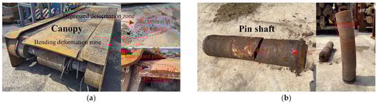
Figure 1.
Failure modes of hydraulic support: (a) Failure modes of the canopy, (b) Failure modes of the pin shaft.
As shown in Figure 2, there is a layer of top coal above the hydraulic support in the LTCC. The existence of top coal increases the thickness of overlying strata, making it simple to build a voussoir beam on the main roof. According to Table 1, regarding sandy mudstone, its lithology is weak and has a good energy absorption effect. Therefore, the gangue and the rock with low lithology absorb most of the impact energy generated by the movement of overlying strata. Additionally, there is a delay in gangue filling in the goaf, which leads to the coal strata near the surface not forming a stable structure, showing a cantilever beam state [,].
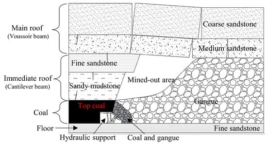
Figure 2.
Coupling of roof-top coal-hydraulic support in the LTCC face.
The rock strata that cannot be self-stabilized and collapse in the caving zone are collectively referred to as the immediate roof []. Due to the rock strata’s different fracture locations and lithology, there are two types of immediate roofs: the lower immediate roof and the upper immediate roof. In order to quantitatively analyze the impact load caused by the instability of the upper immediate roof on the hydraulic support [], the thickness HZ of the immediate roof can be defined as Equation (1):
where HZ is the thickness of the immediate roof, m; H is the cutting height, m; T is the thickness of the top coal; SA is the subsidence of the main roof, m; C is the thickness of residual coal, m; KA is a constant under certain roof conditions [], which is set to 1.4.
The subsidence of the main roof SA can be defined as Equation (2):
where KS is the main roof subsidence coefficient [], which is set to 0.2.
The thickness of residual coal C can be defined as Equation (3):
where η is the recovery rate of the top coal, which is set to 80%; KT is the bulking coefficient of the top coal [], which is set to 1.2.
It is possible to determine the distribution and thickness of the coal seams from the working face of the coal seams. The cutting height is set at 5 m, and the top coal thickness is also set at 5 m. By combining Equations (1)–(3), the thickness of the immediate roof is 20 m. From the overlying strata structure in Table 1, the lithology of the lower immediate roof is sandy mudstone with a thickness of 12 m, and the lithology of the upper immediate roof is fine sandstone with a thickness of 8 m. The main roof’s rock hardness is high, and the structure is stable. The dynamic load generated by the movement instability is difficult to transfer entirely to the LTCC face. Therefore, a load of the main roof on hydraulic support only considers its gravity. The coupling mechanical model of roof-top coal-hydraulic support is established, as shown in Figure 3. Because the tail beam is not the primary bearing component, it has been eliminated from the mechanical model to make it more straightforward. The spring damping model replaces the column.
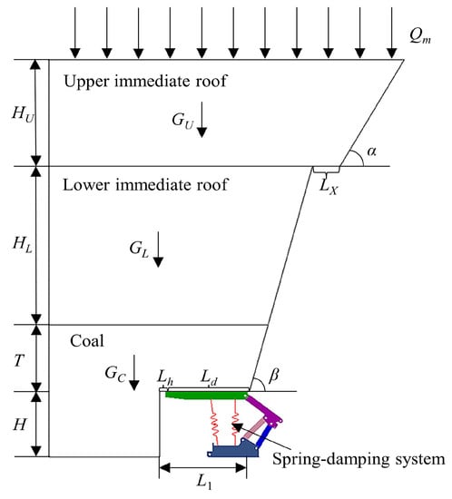
Figure 3.
Coupling mechanical model of roof-top coal-hydraulic support.
2.3. Instability Analysis of the Upper Immediate Roof
According to the location and lithology of the roof, the instability of the upper immediate roof is the main factor causing the pressure on the working face. The different crushing conditions of the lower strata directly affect the stability and rotation angle of the upper immediate roof []. In addition, the instability of the roof has a certain lag. Therefore, the fracture line of the roof is located on the extension line of the coal wall and roof cutting, respectively. There are three forms of the upper immediate roof instability: sliding instability at the coal wall, rotary instability at the coal wall, and rotary instability at the roof cutting. The instability model of the upper immediate roof is established, as shown in Figure 4.
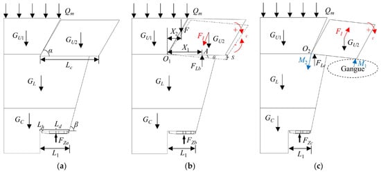
Figure 4.
Instability model of the upper immediate roof: (a) Sliding instability at the coal wall, (b) Rotary instability at the coal wall, (c) Rotary instability at the roof cutting.
The horizontal force cannot be transmitted after the rock strata breaks, which results in the upper immediate roof presenting a cantilever beam state. Different crushing conditions directly affect the cantilever beam’s instability forms [,,]. Figure 4a shows that the cantilever beam showed sliding instability at the coal wall. The working resistance of the hydraulic support can be defined as Equation (4):
where FZa is the working resistance of the hydraulic support under the sliding instability at the coal wall, kN; K is the safety factor, which is set to 1.4; B is the width of the hydraulic support; L1 is the roof control distance, and length is equal to the sum of end face distance and canopy length, m; β is the caving angle of the top coal, which is set to 75°; LX is the length of the hanging roof, which is set to 2 m; γC is the bulk density of the top coal, which is set to 14 kN/m3; γS is the bulk density of the lower immediate roof, which is set to 24.1 kN/m3; γF is the bulk density of the upper immediate roof, which is set to 24.8 kN/m3; Qm is the load of the overlying strata, kN.
According to calculations, the hydraulic support has a working resistance of 18,993.5 kN. In the 08 mining area of Shilawusu, the hydraulic support type is ZF22000/29/55. Therefore, the working resistance reaches 86% of the rated resistance, which meets the working face’s support requirements.
Because of rotary instability, the impact load will be transferred to the lower immediate roof and top coal. This will make the support resistance of the hydraulic support go up. Usually, the fracture length of the upper immediate roof is the same, but fracture positions differ []. Figure 4b shows that the cantilever beam rotated with instability at the coal wall. In the initial state of the rotary, the working resistance of the hydraulic support can be defined as Equation (5):
where FZb1 is the working resistance of the hydraulic support under the initial state of the rotary instability at the coal wall, kN; F is the additional force of the overlying strata, kN; GC is the gravity of the top coal, kN; GL is the gravity of the lower immediate roof, kN; GU1 is the gravity of unbroken upper immediate roof, kN; GU2 is the gravity of the cantilever beam, kN.
According to Equation (5), the working resistance is impacted by the additional force of overlying strata. Figure 4b demonstrates that the support force of the lower immediate roof acts at the A. According to the moment balance [], the additional force can be defined as Equation (6):
where Lc is the length of the cantilever beam, m; X1 is the length of the lower immediate roof support position from the rotary center O1, m; X2 is the length of the additional force position from the rotary center O1, m.
By combining Equations (5) and (6), the changing trend of the working resistance of hydraulic support under the initial state of the rotary instability at the coal wall is shown in Figure 5. Figure 5a demonstrates that, given a constant additional force, the working resistance reduces as the distance between the A and the O1 increases. Under the condition that the distance between the A and the O1 is equal to the roof control distance and the additional force is the farthest from the O1, the working resistance reaches a maximum of 22,890.5 kN, which is 4% more than the rated resistance. Figure 5b reveals that as point A gradually approaches the O1, the variation gradient of the hydraulic support’s working resistance becomes denser.
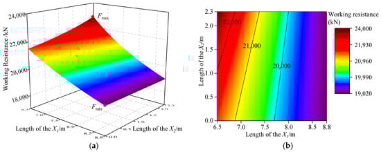
Figure 5.
The changing trend of the working resistance of hydraulic support under the initial state of the rotary instability at the coal wall: (a) X-Y-Z three-dimensional surface diagram, (b) X-Y plane mapping diagram.
With the increased rotary angle, the cantilever beam will not be subjected to additional force. Due to the lower immediate roof force, the cantilever beam began to slow subsidence. According to the d’Alembert principle [], the greater the acceleration during deceleration, the greater the inertial force, and the stronger the impact on hydraulic support []. As shown in Figure 4b, the working resistance of the hydraulic support can be defined as Equation (7):
where FZb2 is the working resistance of the hydraulic support under the deceleration state of the rotary instability at the coal wall, kN; FLb is the lower immediate roof force, kN.
Based on the theorem of the moment of momentum, the lower immediate roof force can be defined as Equation (8):
where mU2 is the mass of the cantilever beam, kg; IO1 is the rotational inertia based on O1, kg·m2.
By combining Equations (7) and (8), the changing trend of the working resistance of hydraulic support under the deceleration state of the rotary instability at the coal wall is shown in Figure 6. Working resistance decreases with the FLb away from the coal wall, as seen in Figure 6. The FLb is located at the O1, and the maximum working resistance is 24,596 kN, which exceeds the rated resistance by 11.8%.
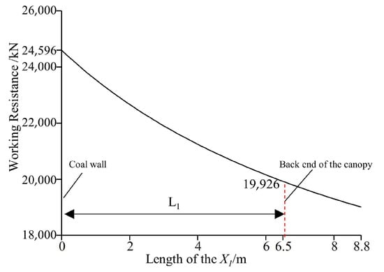
Figure 6.
The changing trend of the working resistance of hydraulic support under the deceleration state of the rotary instability at the coal wall.
It can be seen from Figure 5 and Figure 6 that the factors affecting the working resistance of hydraulic support are the acting force of the lower immediate roof and the additional force position of the overlying strata.
The cantilever beam rotated with instability at the roof cutting, as shown in Figure 4c. The roof cutting is close to the goaf, which will cause the cantilever beam to be easily affected by the gangue []. If the cantilever beam does not collide with the gangue, the working resistance of the hydraulic support can be defined as Equation (9):
where FZc1 is the working resistance of the hydraulic support under the initial state of the rotary instability at the roof cutting, kN; FI is the inertial force of cantilever beam under the subsidence, kN.
According to the moment of momentum theorem, the FI can be defined as Equation (10):
where IO2 is the rotational inertia of the cantilever beam based on O2, kg·m2.
By combining Equations (9) and (10), the hydraulic support’s working resistance under the initial state of the rotary instability at the roof cutting is 20,424.7 kN. Therefore, the rotary instability at the roof cutting has little impact on the working face. This is because the hanging roof is located a considerable distance from the hydraulic support.
Moreover, if the cantilever beam contacts the gangue in the subsidence process [], as shown in Figure 4c, the working resistance of the hydraulic support can be defined as Equation (11):
where FZc2 is the working resistance of the hydraulic support in contact with the gangue, kN; M2 is the momentum of the hydraulic support when the cantilever beam contacts the gangue, kN·m; tc is the collision time of the cantilever beam, s.
After calculation, the working resistance of the hydraulic support in contact with the gangue is 19,145.8 kN. The working resistance is lower as compared to the situation in which the cantilever beam was not in touch with the gangue. The main reason is that after contacting the gangue, the impact dynamic load is consumed by the gangue, which weakens the impact pressure on the hydraulic support.
3. Numerical Simulations
3.1. Dynamic Coupling Model of Roof-Top Coal-Hydraulic Support
The findings of the damage and movement status of the surrounding rock of the actual working face are difficult to obtain by field testing. Consequently, the numerical simulation technology realizes the combination of roof-top coal-hydraulic support and obtains the damage and movement status of the roof and the bearing characteristics of hydraulic support in different roof instability fields.
The dynamic coupling model of roof-top coal-hydraulic support is established, as shown in Figure 7, which comprises the upper immediate roof, lower immediate roof, top coal, and hydraulic support. According to Table 1, the immediate roof is composed of sandy mudstone with a thickness of 12 m and fine sandstone with a thickness of 8 m. The thickness of top coal and the height of mechanical mining are both 5 m.
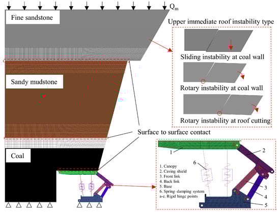
Figure 7.
Dynamic coupling model of roof-top coal-hydraulic support.
To shorten the solution time and guarantee computational precision, the hydraulic support is simplified, ignoring minor supporting components such as the side guard plate and guard plate. Meanwhile, the coal caving process is not taken into account by the numerical simulation, and the tail beam has been taken out of the model because it is not the main bearing component []. The spring damping system is used to replace the column [].
The model was meshed using HyperMesh. Because the accuracy of mesh division affects the simulation results, surrounding rock and the hydraulic support are separated for mesh processing. The mesh size of the surrounding rock is controlled at 200 mm and divided into the hexahedral mesh. The hydraulic support is divided into the tetrahedral mesh, and the mesh size is controlled at 30 mm.
The simulation parameters of the model are set in LS-PREPOST. To simulate the influence of roof instability on the working face, the model only applies full constraints at the bottom of the model in the vertical direction. From the above analysis, the fracture line of the upper immediate roof is located in the extension line of the coal wall and the roof cutting. The grid on the fracture line is removed, and then the degree of freedom of the rotation center is constrained to simulate the different instability forms of the upper immediate roof. To simplify the roof strata and not ignore the role of the main roof, the weight of the main roof is applied to the upper immediate roof as an external load. The rigid area is defined at the shaft hole, and the hinge joints of each component are constrained to form a rotating pair. The surface-to-surface contact is set between the contact types between the rock strata and the top coal and the canopy.
Table 2 shows the mechanical properties of the overlying strata based on the working face’s overlying strata structure. The Holmquist–Johnson–Cook model, often known as the HJC model, is frequently used to examine the mechanical behavior of rock [,,], and adds the keyword MAT_ADD_EROSION to simulate the failure of the material []. The failure criterion of rock is based on reference []. Based on the HJC model theory, the HJC model parameters of the overlying strata are shown in Table 3. The material properties of hydraulic support are shown in Table 4.
Table 2.
Mechanical properties of the overlying strata.
Table 3.
HJC model parameters of the overlying strata.
Table 4.
Material properties of the hydraulic support.
3.2. Spring Damping System of the Column
Under the impact load, the column exhibits elastic properties. Therefore, the spring damping model replaces the column, as shown in Figure 8.
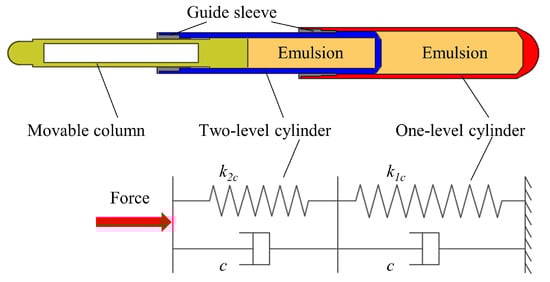
Figure 8.
Equivalent replacement of the column and the spring damping model.
Based on the stiffness definition of the series spring and the fluid–solid coupling theory [], the equivalent stiffness of the cylinder can be defined as Equation (12):
where kic is the equivalent stiffness of the i stage cylinder, kN/mm; Ew is the volume elastic modulus of the emulsion, MPa; Eis is the volume elastic modulus of the i stage cylinder, MPa; Ai is the cross-sectional area of the liquid column in the i stage cylinder, mm2; Liw is the length of the liquid column in the i stage cylinder, mm.
Assuming that the spring is compressed with approximately linear stiffness at each stage, the spring’s axial force-deformation curve is determined, as shown in Figure 9.
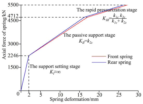
Figure 9.
Axial force-deformation curve of the spring.
4. Results and Discussion
4.1. Crushing Condition of the Top Coal
Based on the lithology of the rock, the top coal has a weak lithology. Different degrees of crushing under impact loading will appear. The contact condition that exists between the top coal and the hydraulic support will vary depending on the kind of crushing that is performed. This is one of the primary causes that contribute to changes in the bearing properties of the hydraulic support. LS-DYNA is used to simulate the dynamic coupling model of roof-top coal-hydraulic support. The dynamic coupling is divided into four stages: initial stage, instability stage 1, instability stage 2, and stability stage. The crushing conditions of the top coal are discussed, as shown in Figure 10.
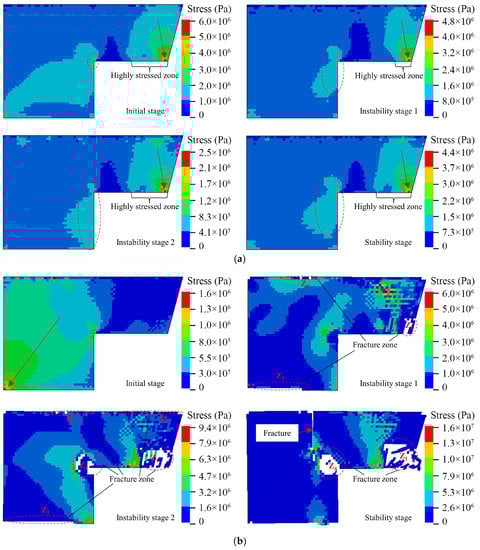
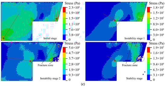
Figure 10.
The crushing condition of the top coal: (a) Sliding instability at the coal wall, (b) Rotary instability at the coal wall, (c) Rotary instability at the roof cutting.
Figure 10a shows the stress distribution of the top coal under the condition that the upper immediate roof slipped with instability at the coal wall, and the top coal is not fractured. This is because, in the event of sliding instability, the load of the top coal is mostly derived from the weight of the overlying strata, and the stress on the top coal does not exceed its compressive strength. Consequently, the impact dynamic force induced by the sliding instability of the upper immediate roof will not result in the top coal being fractured. By combining Equation (4), the working resistance of the hydraulic support meets the support requirements of the working face. In addition, the location of the stress concentration is at the coal wall and behind the top coal. Above the canopy is the highly stressed zone of the top coal. The stress is greatest at the point of contact between the top coal and the rear end of the canopy, and the outward stress gradually decreases and shows a trend of annular diffusion. The analysis of reference [] also supports this result. However, at different stages of dynamic coupling, the range and stress of the highly stressed zone change constantly. This is because the repeated support of the canopy causes a continual change in the contact area between the top coal and the canopy, and the impact dynamic load induced by the contact collision is always changing. Therefore, as a component in direct contact with the top coal, the canopy should meet the strength requirements and have sufficient top coal coverage and the ability to adapt to random contact collision.
The stress of the top coal above the canopy is low in the initial condition of rotary instability of the upper immediate roof at the coal wall, as illustrated in Figure 10b, and the stress from the coal wall to the front of the working face progressively develops. During the instability stage of dynamic coupling, the impact dynamic load on the top coal induced by the rotary collapse of the upper immediate roof is much higher than it was during the sliding instability stage. As a result, the top coal is progressively split apart during this stage. As the degree of crushing of the top coal increases, the coal wall also fractures. In the end, cracks form in front of the coal wall, and the top coal is in a plastic condition. The zone of significant fractures is mostly concentrated above the lower top coal and coal wall. This conclusion is supported by reference []. This is because the top coal is exposed to a considerable impact of dynamic stress during the rotary instability process, and there are many contact collisions between the top coal and the canopy. The lower top coal is constrained and squeezed, resulting in stress concentration and gradual fragmentation. Because the lower top coal is being crushed, the stability of the coal wall is being compromised. As a result, the coal wall itself is being compromised, and cracks are appearing in front of the working face.
Under the initial condition of rotary instability of the upper immediate roof at the roof cutting, as shown in Figure 10c, the stress in the front of the working face and the lower top coal is greater, and it progressively decreases toward the coal wall. During the stage of dynamic coupling known as instability, the lower top coal is broken, a stress concentration takes place at the coal wall, and the contact region between the top coal and the lower immediate roof is broken as a result of excessive extrusion pressure. This conclusion is supported by reference []. Compared with the rotary instability at the coal wall, the impact dynamic load caused by the rotary instability at the roof cutting is much smaller, and the crushing degree of top coal is also smaller. Despite the stress concentration at the coal wall, the coal wall itself is still in a dynamic stable state. Combined with Figure 4c and reference [], this is because the unstable rock block is far from the hydraulic support and close to the goaf, and most of the impact energy is absorbed by the gangue in the goaf. However, there are hidden dangers in the stress concentration at the coal wall. The prevention and control measures of rib spalling should be strengthened to avoid the instability of the coal wall and improve the support effect of hydraulic support.
4.2. Bearing Characteristics of the Canopy
Canopy is one of the key bearing components of hydraulic support, and its bearing characteristics affect the bearing characteristics of hydraulic support. Therefore, the vertical displacement and stress distribution of the canopy at the most dangerous time are selected, as shown in Figure 11. Due to the symmetrical structure of hydraulic support, the stress distribution above and below the canopy is analyzed with the symmetrical plane of the canopy as the interface. At the same time, the vertical displacement change from the front to the rear of the canopy is examined using the canopy’s median line as the sampling line.
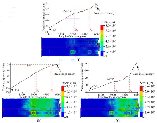
Figure 11.
The vertical displacement and stress distribution of the canopy: (a) Sliding instability at the coal wall, (b) Rotary instability at the coal wall, (c) Rotary instability at the roof cutting.
The sliding instability of the upper immediate roof at the coal wall causes the mean stress of the canopy to be 200 MPa, and the stress concentration is mostly situated at the front column sockets and the rear end of the canopy, as shown in Figure 11a. This is because the support area in front of the canopy is large, resulting in greater pressure on the front column. For this reason, it is necessary to increase the strength of the column sockets and the auxiliary ribbed plate. On the other hand, the displacement of the front end of the canopy is the largest, and the subsidence is 8.7 mm. The subsidence gradually decreases along the length of the canopy, and the overall trend shows a downward trend. The variation in subsidence between the support intervals of the front and rear columns is 1.41 mm. This is because the top coal is not fractured, and the support of the front and rear columns ensures the canopy’s support state, but the highly stressed zone of the top coal is positioned at the back end of the canopy. The rear end of the canopy will be subjected to local dynamic stress as a result of repetitive contact and collision between the top coal and the canopy, resulting in bending deformation. The bending deformation at the back end of the canopy is also shown in Figure 1a. To prevent bending at the rear end of the canopy from disrupting the attitude control of the canopy, it is also important to ensure that there is no interference between the back end of the canopy and the caving shield. Additionally, the support area at the back end of the canopy should also be reinforced.
As shown in Figure 11b, under the rotary instability of the upper immediate roof at the coal wall, the mean stress of the canopy is 480 MPa. The stress between the front and rear columns is large and distributed regularly, and the maximum stress appears in the front column sockets. The displacement of the front end of the canopy is the largest, and the subsidence is 139 mm. Compared with other types of instability, the subsidence angle of the canopy is the largest when the upper immediate roof is unstable at the coal wall. This is because in the process of rotary instability, the top coal is subjected to a large impact dynamic load, and the lower top coal is squeezed and constrained to appear more broken, resulting in a large amount of crushed coal concentrated in the front end of the canopy. The canopy has a significant subsidence angle due to the support it receives from the front and back columns, and the column sockets are especially prone to experiencing stress concentrations due to their location. Therefore, in order to avoid the decrease of the support capacity caused by the uneven bearing of the canopy after the large crushing of the top coal, box-like structures and reinforcing ribs can be set between the column socket and the canopy to ensure that the canopy can better bear impact dynamic load, and the stress distribution of the column sockets is more uniform.
As shown in Figure 11c, the mean canopy stress under rotating instability of the top immediate roof during roof cutting is 380 MPa. The majority of the stress concentration is situated at the rear end of the canopy, and the edge ribbed plate, particularly the stress at the rear end of the canopy, is near the yield stress. This is because the majority of the crushed coal falls on the rear end of the canopy, and the local collision impact concentrates the stress at the back end of the canopy. Therefore, in processing and designing the canopy, the rear end of the canopy and the main ribbed plate should be reinforced.
4.3. Dynamic Response of the Hinged Joint between the Canopy and the Caving Shield
The impact dynamic load needs to be transmitted downward to other components and floor strata for the hydraulic support. The hinged pin shafts connecting adjacent components play a key role in the load transfer process. The stress condition of hinged pin shafts affects the underground safety support. Figure 1b shows the typical failure modes of the hinged pin shafts. Therefore, to analyze the influence of different forms of movement instability on the force of the hinged pin shafts, the load of the hinged joint between the canopy and the caving shield under different instability forms is compared, as shown in Figure 12. Load curve of the hinged joint between the canopy and the caving shield.
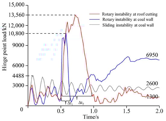
Figure 12.
Load curve of the hinged joint between the canopy and the caving shield.
As shown in Figure 12. Load curve of the hinged joint between the canopy and the caving shield., under the sliding instability of the upper immediate roof at the coal wall, the load of the hinged joint is in a damped oscillation state. The peak value of the load is 4488 kN, and the stable value is 2600 kN. In the event of rotating instability of the upper immediate roof, the load of the hinged joint grows rapidly and varies violently, but the different positions of the rotary instability lead to the change of the peak and stable value of the load. Compared with the rotary instability at the coal wall, under the rotary instability at the roof cutting, the peak value of the load is 1.25 times higher, which is 13,560 kN. However, the stable value of the load is the smallest of the three instability forms, at only 1300 kN. On the contrary, in the case of rotary instability at the coal wall, the stable value of the load is the largest, which is 6950 kN. This is because the cutting line is close to the hinged joint between the canopy and caving shield, and the hinged joint will continue to receive the impact dynamic load. At the same time, because the unstable rock block at the roof cutting is also close to the goaf, this will cause the impact energy to be absorbed by the gangue in the goaf, so in the case of the rotary instability at the roof cutting, the fluctuation gradient of the load is the largest. In summary, different forms of movement instability of the upper immediate roof cause the hinged joint load to fluctuate. The impact dynamic load of the canopy is affected by the crushing state of the top coal, resulting in severe stress on the hinged pin shafts and altering the peak and steady value of the load.
Therefore, to meet the requirements of load transfer and ensure the safety and reliability of the hydraulic support, the pin shaft should use high-strength materials and have sufficient toughness to avoid bending fractures due to impact dynamic load. In addition, the buffer energy absorption structure can be used to weaken the impact load of the pin shaft caused by the roof instability and ensure the stability between the bearing components and the support attitude of the hydraulic support.
5. Conclusions
In the LTCC face, the roof, the top coal, and the hydraulic support interact with each other and are always in a dynamic coupling state. In order to study the movement law of the roof and reveal the bearing characteristics of hydraulic support in different surrounding rock fields, the different forms of movement instability of the upper immediate roof are explored, and the dynamic coupling model of roof-top coal-hydraulic support is established. The influence of different instability forms of the upper immediate roof on the crushing condition of the top coal is analyzed, and the bearing characteristics of the canopy under different instability forms are discussed. The following conclusions are obtained:
- (1)
- Combined with the coupling mechanical model of roof-top coal-hydraulic support, the instability effect of the roof is quantitatively analyzed. It is concluded that the main factors affecting the working resistance of hydraulic support are the fracture position of the upper immediate roof, the acting force of the lower immediate roof, the additional force position of overlying strata, and the distribution of gangue in goaf.
- (2)
- The rotary instability of the upper immediate roof leads to the obvious crushing of the top coal, which affects the contact area between the top coal and the canopy. Repeated contact collisions cause serious impact load on the hydraulic support. In particular, the rotary instability of the upper immediate roof at the coal wall causes cracks in front of the coal wall and a large amount of broken coal concentrated at the front end of the canopy. This causes the stress concentration in the coal seam to move forward, which in turn reduces the stability of the coal wall. In the LTCC face, improving the support area of the canopy and effective rib spalling prevention measures are conducive to improving the stability and reliability of the hydraulic support.
- (3)
- The instability of the upper immediate roof affects the state of the top coal, which leads to the uneven bearing of the hydraulic support, and makes the canopy show a downward trend. Although the existence of the column ensures the support performance of the canopy, it is easy for the stress concentration to occur at the column sockets, especially in the front column sockets. Therefore, the box structure and stiffeners can be set between the column socket and the canopy to ensure a more uniform stress distribution at the column socket. In addition, the back-end ribs and side ribs of the canopy will be continuously impacted by the broken and collapsed coal blocks. In the structural optimization, the back-end ribs and side ribs of the canopy can be strengthened.
- (4)
- In the case of rotary instability, the force of the hinged pin shafts is severe, but the peak and stable value of the hinged joint load are quite different due to the different positions of the rotary instability. Under the rotary instability at the coal wall, the stable value of the load is the largest, at 6950 kN. On the contrary, under the rotary instability at the roof cutting, the peak value of the load is the largest, at 13,560 kN. Therefore, the increase in the strength and toughness of the hinged pin shafts are favorable to improve the adaptability of the hydraulic support.
The results provide the research suggestion for the coupling relationship between surrounding rock and hydraulic support and provide references for the bearing characteristics analysis and structural optimization of the hydraulic support. However, there are some limitations to this study. The influence of the coal caving process and the working face advancing process is not considered in this study, so the coupling model of the roof-top coal-hydraulic support including the tail beam can be considered in further research. In addition, early warning of roof instability is an effective means to reduce accident losses in time. Therefore, the study of the roof instability prediction based on multi-source data fusion can be considered in the future as a comparison to this research.
Author Contributions
Conceptualization, Q.Z. and Z.L.; methodology, Q.Z.; software, D.M.; validation, Z.L. and D.M.; formal analysis, Z.L.; investigation, Z.L.; data curation, Z.L.; writing—original draft preparation, Z.L.; writing—review and editing, Z.L.; visualization, Z.L.; supervision, Q.Z.; project administration, L.W.; funding acquisition, Q.Z. All authors have read and agreed to the published version of the manuscript.
Funding
This research was funded by the National Natural Science Foundation of China (Grant No. 51974170, 52104164, 52274132), the Key Research and Development of Shandong Province (Grant No. 2019SDZY01).
Institutional Review Board Statement
Not applicable.
Informed Consent Statement
Not applicable.
Data Availability Statement
Data were curated by the authors and are available upon request.
Conflicts of Interest
The authors declare no conflict of interest.
References
- Xie, H.P.; Ren, S.H.; Xie, Y.C.; Jiao, X.M. Development opportunities of the coal industry towards the goal of carbon neutrality. J. China Coal Soc. 2021, 46, 2197–2211. [Google Scholar] [CrossRef]
- Song, X.M.; Zhu, D.F.; Wang, Z.L.; Huo, Y.M.; Liu, Y.F.; Liu, G.F.; Cao, J.J.; Li, H.C. Advances on longwall fully-mechanized top-coal caving mining technology in China during past 40 years: Theory, equipment and approach. Coal Sci. Technol. 2021, 49, 1–29. [Google Scholar] [CrossRef]
- Yan, S.H.; Xu, G.; Fan, Z.Z. Development course and prospect of the 50 years’comprehensive mechanized coal mining in China. Coal Sci. Technol. 2021, 49, 1–9. [Google Scholar] [CrossRef]
- Wang, J.C.; Yang, S.L.; Wei, W.J.; Zhang, J.W.; Song, Z.Y. Drawing mechanisms for top coal in longwall top coal caving (LTCC): A review of two decades of literature. Int. J. Coal Sci. Technol. 2021, 8, 1171–1196. [Google Scholar] [CrossRef]
- Wang, J.C. Engineering practice and theoretical progress of top-coal caving mining technology in China. J. China Coal Soc. 2018, 43, 43–51. [Google Scholar] [CrossRef]
- Wang, J.C.; Wang, Z.H. Systematic principles of surrounding rock control in longwall mining within thick coal seams. Int. J. Min. Sci. Technol. 2019, 29, 65–71. [Google Scholar] [CrossRef]
- Yu, B.; Yang, J.X.; Liu, C.Y.; Gao, R. Overburden structure and mechanism of rock pressure in large space stope. J. China Coal Soc. 2019, 44, 3295–3307. [Google Scholar] [CrossRef]
- Wang, J.H.; Yu, B.; Kang, H.P.; Wang, G.F.; Mao, D.B.; Liang, Y.T.; Jiang, P.F. Key technologies and equipment for a fully mechanized top-coal caving operation with a large mining height at ultra-thick coal seams. Int. J. Coal Sci. Technol. 2015, 2, 97–161. [Google Scholar] [CrossRef]
- Balasubrahmanyam, N.; Budi, G. Techno-Economic Feasibility of the Longwall Top Coal Caving Method Based on the FTCD Index: A Parametric Case Study in India. Energies 2021, 14, 6115. [Google Scholar] [CrossRef]
- Liu, Z.G.; Fan, Z.L.; Zhang, Y.J. Fracture characteristics of overlying bedrock and clay aquiclude subjected to shallow coal seam mining. Mine Water Environ. 2018, 38, 136–147. [Google Scholar] [CrossRef]
- Singh, G.S.P.; Singh, U.K. Numerical modeling study of the effect of some critical parameters on caving behavior of strata and support performance in a longwall working. Rock Mech. Rock Eng. 2009, 43, 475–489. [Google Scholar] [CrossRef]
- Li, Y.; Ren, Y.Q.; Wang, N.; Jin, X.Y.; Ou, X.J.; Luo, J.B.; Mei, C.Q. Structure form and evolution characteristics of collapsed roof in goaf. J. China Coal Soc. 2021, 46, 3771–3780. [Google Scholar] [CrossRef]
- Qian, M.G. A structural model of overlying strata in longwall working and its application. J. China Univ. Min. Technol. 1982, 11, 6–16. [Google Scholar]
- Wu, S.L.; Liu, S.L. Study on roof movement law and powered support-surrounding rock relationship of fully-mechanized top coal caving mining face. Coal Sci. Technol. 2016, 44, 104–108. [Google Scholar] [CrossRef]
- Yang, S.H.; Jiang, F.X. Research on the relationship between sublevel caving support load and roof structure. Chin. J. Rock Mech. Eng. 1999, 18, 287–290. [Google Scholar]
- Zhang, H.P. Analysis on stability of overburden structure and support resistance in fully mechanized top coal caving mining-taking Baode Coal Mine as an example. Coal Sci. Technol. 2022, 50, 48–53. [Google Scholar] [CrossRef]
- Liu, J.R. Key layer of direct roof and support suitability of fully mechanized top coal caving mining face in ultra thick seam. Coal Sci. Technol. 2009, 37, 1–4+8. [Google Scholar] [CrossRef]
- Wang, J.L.; Yuan, Y.; Tu, S.H.; Li, B. Roof structure characteristics in fully mechanized coalface with large mining height and reasonable loading of support. J. Min. Saf. Eng. 2014, 31, 512–518. [Google Scholar] [CrossRef]
- Wu, F.F.; Yue, X.; Yang, J.X.; Du, B.J.; Zhang, J.; Lv, B. Model of overlying strata structure in large mining height excavating condition and calculation of support working resistance. Geofluids 2022, 2022, 5894735. [Google Scholar] [CrossRef]
- Wu, F.F.; Yu, X.; Zhang, J.; Zhou, Q.C.; Gao, Z.Q.; Liu, S.B. Research on interaction relationship between support and surrounding rock in fault structural area and its application. Lithosphere 2022, 2022, 6997956. [Google Scholar] [CrossRef]
- Zhang, K.; Yang, T.H.; Bai, H.B.; Gamage, R.P. Longwall mining–induced damage and fractures: Field measurements and simulation using FDM and DEM coupled method. Int. J. Geomech. 2018, 18, 04017127. [Google Scholar] [CrossRef]
- Behera, B.; Yadav, A.; Singh, G.S.P.; Sharma, S.K. A numerical modeling approach for evaluation of spalling associated face instability in longwall workings under massive sandstone roof. Eng. Fail. Anal. 2020, 117, 104927. [Google Scholar] [CrossRef]
- Pang, Y.H.; Gong, S.X.; Liu, Q.B.; Wang, H.B.; Lou, J.F. Overlying strata fracture and instability process and support loading prediction in deep working face. J. Min. Saf. Eng. 2021, 38, 304–316. [Google Scholar] [CrossRef]
- Mangal, A.; Paul, P.S. Rock mechanical investigation of strata loading characteristics to assess caving and requirement of support resistance in a mechanized powered support longwall face. Int. J. Min. Sci. Technol. 2016, 26, 1081–1087. [Google Scholar] [CrossRef]
- Xu, Y.X.; Wang, G.F.; Zhang, C.C.; Li, M.Z.; Zhang, J.H. Investigation and practice of the reasonable cutting height at longwall top coal caving face with super-large mining height in hard and extra-thick coal seams. J. Min. Saf. Eng. 2020, 37, 715–722. [Google Scholar] [CrossRef]
- Bu, T.T. Dynamic response relationship between roof movement and deformation of roadway in fully mechanized caving face of deep and thick coal seam. J. Min. Strata Control Eng. 2021, 3, 50–58. [Google Scholar] [CrossRef]
- Tian, Y.; Gong, P.L.; Sun, D.Z.; Sun, H.C. Determination of roof support strength at the working face in extra-thick coal seam under goaf. Min. Res. Dev. 2022, 42, 108–112. [Google Scholar] [CrossRef]
- Wang, G.F.; Pang, Y.H.; Li, M.Z.; Ma, Y.; Liu, X.H. Hydraulic support and coal wall coupling relationship in ultra large height mining face. J. China Coal Soc. 2017, 42, 518–526. [Google Scholar] [CrossRef]
- Wang, G.F.; Pang, Y.H. Shield-roof adaptability evaluation method based on coupling of parameters between shield and roof strata. J. China Coal Soc. 2016, 41, 1348–1353. [Google Scholar] [CrossRef]
- Wang, G.F.; Pang, Y.H. Full-mechanized coal mining and caving mining method evaluation and key technology for thick coal seam. J. China Coal Soc. 2018, 43, 33–42. [Google Scholar] [CrossRef]
- Islavath, S.R.; Deb, D.; Kumar, H. Numerical analysis of a longwall mining cycle and development of a composite longwall index. Int. J. Rock Mech. Min. Sci. 2016, 89, 43–54. [Google Scholar] [CrossRef]
- Verma, A.K.; Deb, D. Numerical analysis of an interaction between hydraulic-powered support and surrounding rock strata. Int. J. Geomech. 2013, 13, 181–192. [Google Scholar] [CrossRef]
- Arasteh, H.; Esmaeili, K.; Saeedi, G.; Farsangi, M.A.E. Discontinuous modeling of roof strata caving in a mechanized longwall mine in Tabas coal mine. Int. J. Geomech. 2022, 22, 4022040. [Google Scholar] [CrossRef]
- Rajwa, S.; Janoszek, T.; Prusek, S. Model tests of the effect of active roof support on the working stability of a longwall. Comput. Geotech. 2020, 118, 103302. [Google Scholar] [CrossRef]
- Xie, D.L.; Han, J.; Zhang, H.D.; Wang, K.; Du, Z.W.; Miao, T.Y. Risk assessment of water inrush from coal seam roof based on combination weighting-set pair analysis. Sustainability 2022, 14, 11978. [Google Scholar] [CrossRef]
- Qin, L.T.; Gu, Y.S.; Wu, Z. Study on ground pressure law of large mining height fully mechanized mining face in deep compound coal seam. Coal Mine Mod. 2021, 30, 99–101+105. [Google Scholar] [CrossRef]
- Fan, K.F.; Li, W.P.; Wang, Q.Q.; Liu, S.L.; Xue, S.; Xie, C.Y.; Wang, Z.K. Formation mechanism and prediction method of water inrush from separated layers within coal seam mining: A case study in the Shilawusu mining area, China. Eng. Fail. Anal. 2019, 103, 158–172. [Google Scholar] [CrossRef]
- Shan, R.L.; Bai, Y.; Ju, Y.; Han, T.Y.; Dou, H.Y.; Li, Z.L. Study on the triaxial unloading creep mechanical properties and damage constitutive model of red sandstone containing a single ice-filled flaw. Rock Mech. Rock Eng. 2020, 54, 833–855. [Google Scholar] [CrossRef]
- He, Z.Q.; Xie, H.P.; Gao, M.Z.; Deng, G.D.; Peng, G.Y.; Li, C. The fracturing models of hard roofs and spatiotemporal law of mining-induced stress in a top coal caving face with an extra-thick coal seam. Geomech. Geophys. Geo-Energy Geo-Resour. 2020, 7, 2. [Google Scholar] [CrossRef]
- Huang, B.; Min, F.S.; Liu, C.Y.; Li, J.W.; Yang, J.X. Roof failure features and support resistance determination for thick coal seam fully mechanized top coal caving in Xichuan Coal Mine. Coal Eng. 2016, 48, 80–83. [Google Scholar] [CrossRef]
- Liu, C.; Li, H.M.; Mitri, H.; Jiang, D.J.; Li, H.G.; Feng, J.F. Voussoir beam model for lower strong roof strata movement in longwall mining—Case study. J. Rock Mech. Geotech. Eng. 2017, 9, 1171–1176. [Google Scholar] [CrossRef]
- Young, M.; Walton, G.; Holley, E. Investigation of factors influencing roof stability at a Western U.S. longwall coal mine. Int. J. Min. Sci. Technol. 2019, 29, 139–143. [Google Scholar] [CrossRef]
- Ning, J.; Xu, G.; Zhang, C.H.; Sun, M.L. Mechanical model and fracturing characteristics of multi-area supporting roof in fully mechanized mining working face. J. China Coal Soc. 2020, 45, 3418–3426. [Google Scholar] [CrossRef]
- Wu, F.F.; Yue, X.; Liu, C.Y.; Yu, C.H.; Liu, Q.W.; Li, C.; Du, B.J.; Yang, P.J.; Chen, Y.Q. Movement law of overburden in steep inclined ultra thick seam and calculation of support working resistance. J. Min. Saf. Eng. 2022, 39, 499–506. [Google Scholar] [CrossRef]
- Behera, B.; Yadav, A.; Singh, G.S.P.; Sharma, S.K. Numerical Modeling Study of the Geo-mechanical Response of Strata in Longwall Operations with Particular Reference to Indian Geo-mining Conditions. Rock Mech. Rock Eng. 2019, 53, 1827–1856. [Google Scholar] [CrossRef]
- Ju, J.F.; Xu, J.L.; Wang, Q.X. Cantilever structure moving type of key strata and its influence on ground pressure in large mining height workface. J. China Coal Soc. 2011, 36, 2115–2120. [Google Scholar] [CrossRef]
- Zeng, Q.L.; Li, Z.J.; Wan, L.R.; Ma, D.J.; Wang, J.T. Research on Dynamic Characteristics of Canopy and Column of Hydraulic Support under Impact Load. Energies 2022, 15, 4638. [Google Scholar] [CrossRef]
- Zeng, Q.L.; Meng, Z.S.; Wan, L.R.; Wang, C.L. Analysis on Force Transmission Characteristics of Two-Legged Shield Support under Impact Loading. Shock Vib. 2018, 2018, 3854684. [Google Scholar] [CrossRef]
- Ling, T.L.; Wu, S.F.; Liu, D.S.; Liang, S.F.; Li, C.; Ma, J.H. Determination of Holmquist-Johnson-Cook model parameters for sandstone. J. China Coal Soc. 2018, 43, 2211–2216. [Google Scholar] [CrossRef]
- Islam, M.J.; Swaddiwudhipong, S.; Liu, Z.S. Penetration of Concrete Targets Using a Modified Holmquist–Johnson–Cook Material Model. Int. J. Comput. Methods 2013, 9, 1250056. [Google Scholar] [CrossRef]
- Wen, L.; Li, X.B.; Wu, Q.H.; Su, W. Study on parameters of Holmquist-Johnson-Cook moder for granite porphyry. Chin. J. Comput. Mech. 2016, 33, 725–731. [Google Scholar] [CrossRef]
- Wan, L.R.; Wang, J.T.; Zeng, Q.L.; Ma, D.J.; Yu, X.H.; Meng, Z.S. Vibration Response Analysis of the Tail Beam of Hydraulic Support Impacted by Coal Gangue Particles with Different Shapes. ACS Omega 2022, 7, 3656–3670. [Google Scholar] [CrossRef] [PubMed]
- Sheorey, P.R. Empirical Rock Failure Criteria; CRC Press: Boca Raton, FL, USA, 1997. [Google Scholar]
- Huo, Y.M.; Song, X.M.; Sun, Z.D.; Wang, Z.L.; Li, H.C. Evolution of mining-induced stress in fully mechanized top-coal caving under high horizontal stress. Energy Sci. Eng. 2020, 8, 2203–2215. [Google Scholar] [CrossRef]
Disclaimer/Publisher’s Note: The statements, opinions and data contained in all publications are solely those of the individual author(s) and contributor(s) and not of MDPI and/or the editor(s). MDPI and/or the editor(s) disclaim responsibility for any injury to people or property resulting from any ideas, methods, instructions or products referred to in the content. |
© 2023 by the authors. Licensee MDPI, Basel, Switzerland. This article is an open access article distributed under the terms and conditions of the Creative Commons Attribution (CC BY) license (https://creativecommons.org/licenses/by/4.0/).