Article

Noise Reduction in Helicopter Cabins Using Microperforated Panel Composite Sound Absorption Structures

1
National Key Laboratory of Helicopter Dynamics, Nanjing University of Aeronautics and Astronautics, Nanjing 210016, China
2
Nanjing Chenguang Group Co., Ltd., Nanjing 210006, China
*
Author to whom correspondence should be addressed.
Appl. Sci. 2023, 13(14), 8153; https://doi.org/10.3390/app13148153
Submission received: 20 June 2023 / Revised: 8 July 2023 / Accepted: 11 July 2023 / Published: 13 July 2023
(This article belongs to the Special Issue Application of Metamaterials in Aerospace Engineering)

Abstract

:
The high level of noise in helicopter cabins considerably compromises the comfort and safety of the pilot and passengers. To verify the feasibility and effectiveness of microperforated panel composite sound absorption structures for noise suppression in helicopter cabins, simulation and experimental studies were conducted on a model of a light helicopter cabin. First, three microperforated composite sound absorption structures for the helicopter cabin wall panel were designed. Then, a finite element model of the main gear/body acoustic vibration coupling was established to obtain the target frequencies of the microperforated composite sound absorption structures; the acoustic effect was verified via simulation. Finally, a model helicopter cabin equipped with the three microperforated composite sound absorption structures was built, and a cabin noise test was performed. The test results showed that the combined microperforated panel acoustic structure and microperforated panel–porous material composite structure realized an overall cabin sound pressure level attenuation of 8–10 dB, on average, in a wide frequency range of 500–2000 Hz, with an amplitude of more than 20 dB. The microperforated panel–acoustic supermaterial composite structure achieved low-frequency sound absorption in the frequency range of 300–450 Hz. The sound absorption effect reached 50%, and it also exhibited good noise reduction effects in the middle- and high-frequency bands.

1. Introduction

Helicopter cabin noise is highly complex, comprising noise generated from a variety of sources, including aerodynamic noise caused by the rotor system, transmission system, engine, and other components [1]. The main gearbox is a key component of the helicopter transmission system, and the impact excitation generated by gear meshing causes structural vibrations and induces cabin noise, whose frequency is usually in the range of 200–2000 Hz. This noise has a high sound pressure level covering the sensitive range of human ear hearing, resulting in cabin noise levels exceeding 95 dB and even reaching 110 dB in many helicopter models [2]. Therefore, the noise generated by the main gear is one of the key factors limiting the development of new helicopters [3].
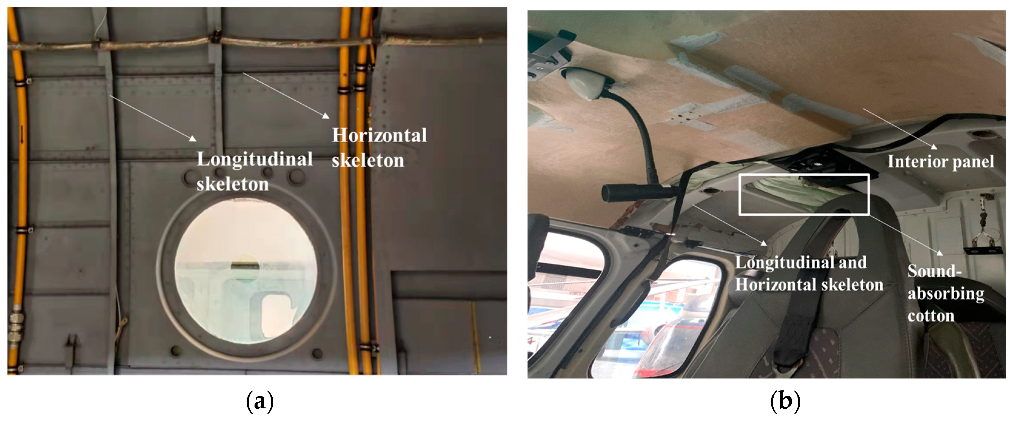
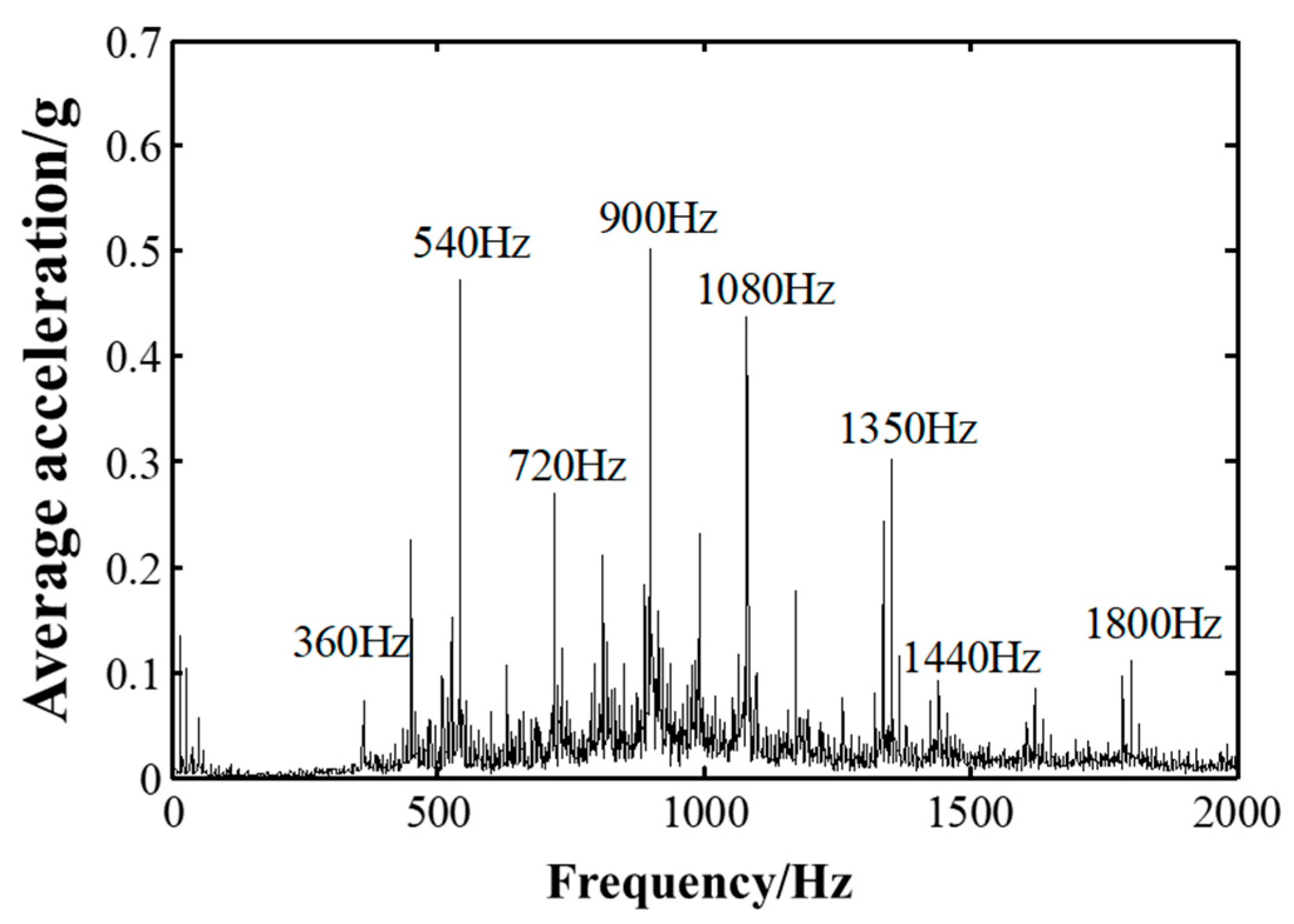
Figure 1 depicts the cabin noise spectrum of an S-76 helicopter cabin [4,5]. Clearly, the helicopter cabin noise is mostly medium–high-frequency line-spectrum noise with multiharmonic, multifrequency, and high-level characteristics. Currently, helicopter cabin noise control is mainly based on the addition of porous sound-absorbing materials, honeycomb structures, and damping materials to the cabin wall sandwich to reduce sound energy propagation through vibration isolation and sound absorption techniques [6,7]. Two helicopter cabin wall panel structures are illustrated in Figure 2. As can be seen, the helicopter nacelles typically have a semi-thin-walled structure consisting of an external skin and longitudinal and transverse skeletons. Some civil helicopter models are equipped with interior panels, and their air-back cavities are often filled with sound-absorbing cotton and foam for acoustic treatment. This type of material has limited ability to control low- and medium-frequency noises and has a large additional mass, which affects the overall performance of the helicopter to some extent [5].
Sound absorption and isolation methods are easy to implement, and the noise reduction effect is stable; hence, almost all helicopter manufacturers are currently using such methods. However, these methods have certain limitations, including large additional weights and poor low-frequency effects. In recent years, a new type of acoustic structure, called the microperforated panel (MPP) sound absorption structure, has been developed. It has the advantages of good sound absorption, a simple structure, and low weight compared with traditional acoustic structures or materials [8]. The MPP structure has been widely used in the fields of building and road construction [9,10,11,12,13]; however, thus far, its application in helicopters has rarely been studied. To reduce the linear-spectrum noise in the helicopter cabin caused by the gear meshing of the main gearbox, the original structure can be modified using the air-back cavity and by converting the interior trim panel into an MPP [14]. This strategy can not only reduce the noise but also meet the size and weight requirements of the helicopter. Models without interior panels can be retrofitted with MPPs to form a microperforated acoustic structure, which can effectively suppress cabin noise and satisfy the weight requirements.
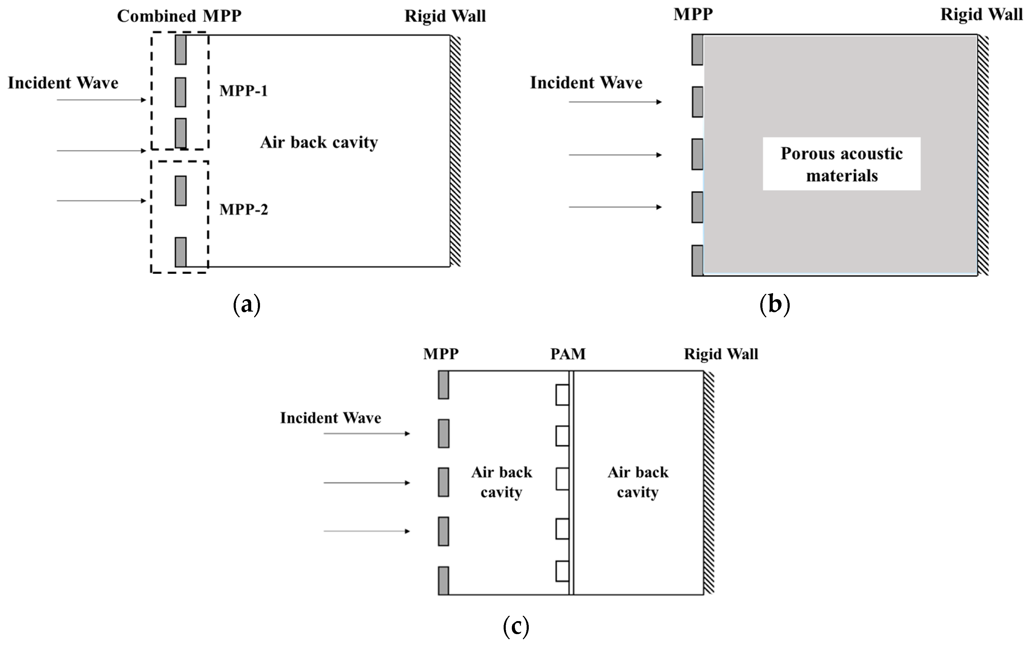
According to the Helmholtz resonance principle, the sound absorption characteristics of a microperforated plate acoustic structure exhibit a single resonance peak. If used for noise reduction in helicopter cabins, the sound absorption band of the MPP structure will need to be broadened. The sound absorption band is mostly concentrated in the zones of middle and high frequency; the low-frequency noise suppression effect of the structure is not significant and cannot meet the requirement for noise reduction in helicopter cabins. At present, most of the domestic and international research on sound absorption and insulation materials still remains in the research stage of a single material, and it is difficult to achieve a good noise reduction effect in the wide band. Therefore, efficient new composite materials [15,16,17,18] are one of the trends of future development. Hence, this study proposes three composite MPP acoustic structures for noise reduction in helicopter cabins, namely, a combined MPP acoustic structure (hereinafter referred to as the Combined MPP), an MPP–porous material composite structure (hereinafter referred to as MPP+Porous), and an MPP–acoustic supermaterial composite structure (hereinafter referred to as MPP+PAM), whose basic configurations are shown in Figure 3. The combined MPP consists of parallel MPPs with different properties, aiming to absorb multilinear-spectrum, high-level noise and broaden the absorption band. The MPP+Porous structure modifies the original interior panel for acoustic treatment through an installed MPP, filling the back cavity with porous acoustic materials to broaden the absorption band. The MPP+PAM combines an MPP and acoustic supermaterial of the thin plate type placed in the back cavity to suppress the noise in the middle- and low-frequency bands.
This study takes helicopter cabin noise control as its research problem, focusing on noise in the middle- and high-frequency bands of the multilinear spectrum caused by gear meshing of the main gear reducer, and investigates the feasibility and effectiveness of using MPP composite sound absorption structures for noise suppression in helicopter cabins. The remainder of this paper is organized as follows. Section 2 establishes the mathematical models of the absorption coefficient equations of the combined microperforated plate acoustic structures. Section 3 describes the simulation of the sound field in a model of a helicopter cabin equipped with microperforated plate composite acoustic structures. Section 4 presents the experiments on the sound field in the helicopter cabin model with the application of the microperforated plate composite acoustic structures. Finally, Section 5 concludes the paper.

2. Methodology

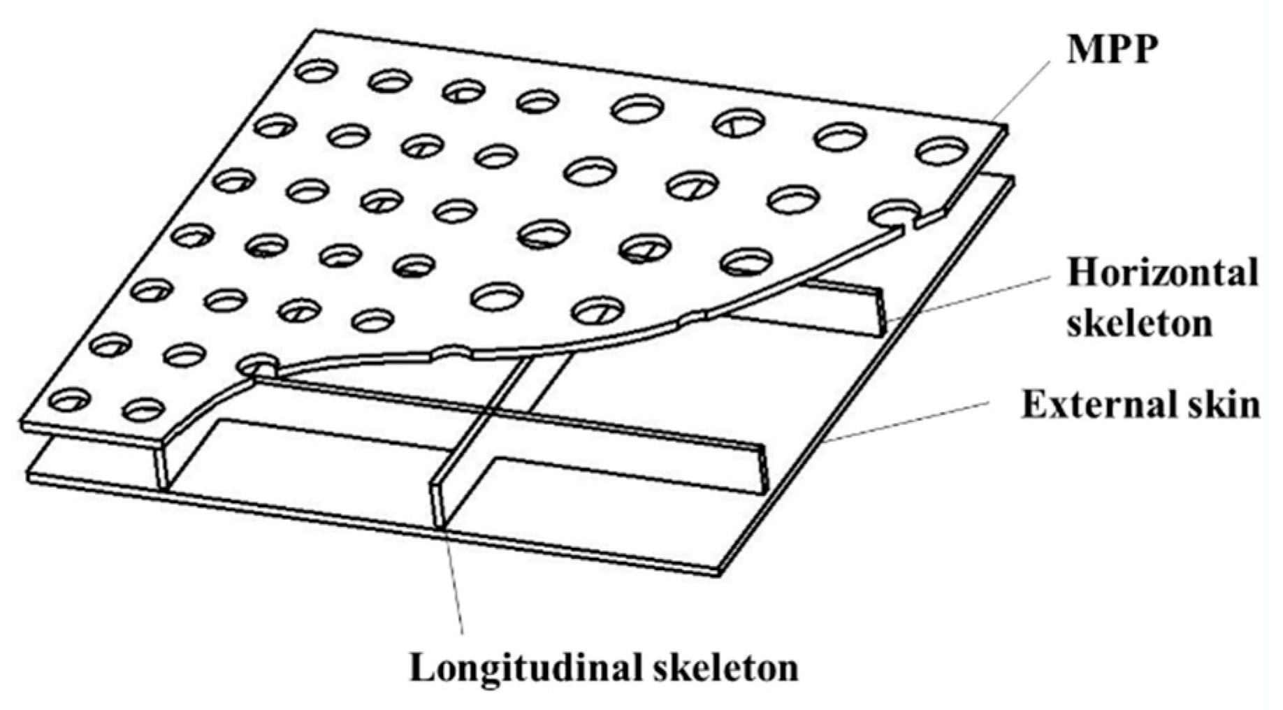
Figure 4 displays a schematic of the MPP acoustic structure for noise reduction in the helicopter cabin. The sound absorption structure mainly consists of a microperforated plate, an air-back cavity, and the external skin of the nacelle. Because the microperforated plate acoustic structure is not sensitive to material properties, to reduce the weight, a thin plate of polymer material with microperforations is used. The air-back cavity and rigid skin wall plate, with a certain thickness at the rear, constitute the microperforated plate acoustic structure. The following concepts, based on the transfer matrix method combined with the series–parallel relationship, establish three MPP composite sound absorption structures for the sound absorption characteristic model.

2.1. Mathematical Model of the MPP

The transfer matrix of a microperforated plate [19,20] M is:
M = 1 Z 1 0 1
and its acoustic impedance rate can be expressed as:
Z 1 = p ρ c ( r 1 + j ω m 1 )
The transfer matrix of the air back cavity C is given by:
C = cos ( ω D 1 / c ) j ρ c sin ( ω D 1 / c ) j ρ c sin ( ω D 1 / c ) cos ( ω D 1 / c )
where D1 is the depth of the air back chamber.
The transfer matrix of the MPP is as follows:
Π a = M C = Π 11 Π 12 Π 21 Π 22
Because the terminal surface of the acoustic structure is a rigid wall plate, the acoustic impedance of the MPP can be obtained as:
Z = 11 21
The reflection coefficient R is as follows:
R = Z ρ c Z + ρ c
The absorption coefficient of the MPP under the conditions of positive sound wave incidence α is:
α = 1 R 2

2.2. Mathematical Model of the MPP+Porous Structure

Based on the sound absorption mechanism of porous sound-absorbing materials, the Johnson–Champoux–Allard model is chosen to describe the sound absorption coefficient of the material. The transfer matrix of a porous sound-absorbing material P is:
P = cos ( k p D p ) j sin ( k p D p ) j Z p sin ( k p D p ) cos ( k p D p )
where kp and Zp are the wave number and characteristic impedance of the porous material, respectively, which are calculated as follows:
k p = ω ρ ( ω ) K ( ω )
Z p = ρ ( ω ) K ( ω )
where ρ(ω) and K(ω) are the effective density and bulk modulus of the porous material, respectively, which are expressed as:
ρ ( ω ) = α ρ 0 ϕ 1 j σ ϕ α ρ 0 ω 1 + j 4 α 2 ρ 0 ω η σ 2 ϕ 2 Λ 2
K ( ω ) = γ P 0 ϕ γ γ 1 1 j 8 η ω ρ 0 P r Λ 2 1 + j ω ρ 0 P r Λ 2 16 η 1
Here,
Λ = 1 b ( 8 α η σ ϕ ) 1 2 , Λ = 1 b ( 8 α η σ ϕ ) 1 2
where α is the curvature factor, σ is the flow resistance, ϕ is the porosity of the porous material, η is the dynamic viscosity of air, γ is the specific heat capacity ratio of air, P0 is the static pressure of air, Pr is the Prandtl number of air, b is the cross-sectional shape factor of the pores, b′ is the scale factor of the pores, and Λ and Λ′ are the viscous and thermal characteristic lengths, respectively.
The porous material used in this study was melamine sponge, which is an open-cell porous foam acoustic material with an excellent sound absorption performance and is widely used in aircraft adiabatic insulation materials, payload racks, and the mufflers of the International Space Station. It has a good suppression effect on cabin noise, and its relevant parameters are listed in Table 1.
The transfer matrix of the MPP+Porous structure is:
Π b = M P = Π 11 Π 12 Π 21 Π 22
The absorption coefficient can be obtained by substituting the values into Equations (5)–(7).

2.3. Mathematical Model of the MPP+PAM

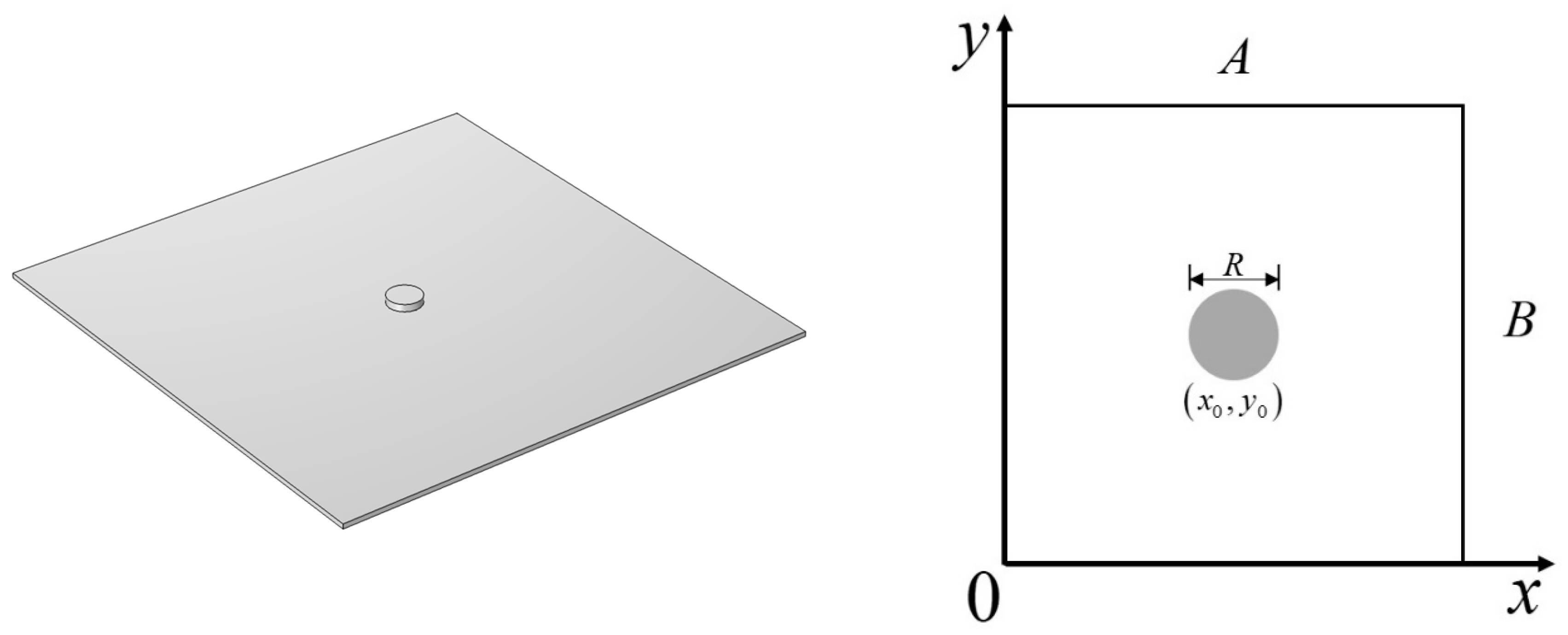
The acoustic absorption mechanism of a thin-plate acoustic metamaterial is primarily based on the principle of local resonance, serving to achieve the total absorption of a certain frequency of acoustic waves. In this study, the thin-plate acoustic metamaterial was composed of a rectangular aluminum thin plate and a small cylindrical iron block, whose individual metamaterial structure is depicted in Figure 5. The following derivation of the absorption coefficient of this composite structure is based on the modal superposition method.
The transfer matrix of the PAM is:
N = 1 Z P A M 0 1
where ZPAM is the impedance rate of the PAM.
A mass block with the dimensional diameter Rmass is attached to the thin plate. In the Cartesian coordinate system, the coordinates of the center of the mass block circle are assumed to be (x0, y0), and the equation of the vibration motion of the thin plate with the mass block attached is:
ρ s 2 w t 2 + ρ m a s s H 2 w t 2 + D 4 w = 2 p i n e j ω t 2 ρ 0 c 0 w t
where ρmass is the surface density of the mass block, pin is the amplitude of the incident acoustic wave, H is the characteristic impedance of air, and ρ0c0 is the combination of four step functions characterizing the impact of the mass block equation. For the position of the mass block to take 1, and the other positions of the thin plate to take 0, the expression is:
H = H x x 0 H x x 0 R / 2 H y y 0 H y y 0 R / 2
The vibration displacement of a thin plate can be expressed as:
w x , y , t = m = 1 M ϕ m x , y q m t
where m is the modal number, ϕm (x, y) is the modal type function of each order for a thin plate under fixed constraints, and qm (t) is the generalized coordinate corresponding to the modal type function of each order. Here,
ϕ m x , y = 2 sin k x x sin k y y
q m t = q ˜ m e j ω t
Substituting Equation (20) into Equation (18), multiplying by the orthogonal modal function ϕn (x, y), and integrating over the surface of the thin plate, we obtain:
ω 2 M m q ˜ m ω 2 n = 1 N Q m , n q ˜ m + K m q ˜ m + E m q ˜ m = 2 p i n H m j ω D m q ˜ m
Equation (21) can be expressed as a matrix using the expression:
ω 2 M p q ˜ ω 2 Q q ˜ + K q ˜ + E q ˜ + j ω D q ˜ = 2 p i n L
where [Mp] is the sheet mass matrix, [Q] is the additional mass matrix, [E] is the damping matrix with a damping factor of 0.15, [K] is the sheet stiffness matrix, [D] is the flexural stiffness matrix, and L is the nodal displacement.
The modal migration matrix [Y] can be expressed as:
Y = j ω ω 2 M p ω 2 Q + K + D + j ω E
The amplitude of the structural vibration velocity of the PAM at the vertical incidence of the acoustic wave is:
V = Y × 2 p i n L m
The average structural vibration velocity of the PAM is:
v ¯ = 1 A B 0 A 0 B v x , y d y d x = 1 A B H T V
The impedance of the PAM is the ratio of the sound pressure difference between the two sides of the structure to the average vibration velocity of the structure, which can be expressed as:
Z P A M = p 1 v ¯
The transfer matrix of MPP+PAM is:
Π c = M C 1 N C 2 = Π 11 Π 12 Π 21 Π 22
The absorption coefficient can be obtained by substituting the values into Equations (5)–(7).

2.4. Design Parameters

Based on the number of teeth and speed calculation, it was concluded that the internal gear meshing frequencies of this main reducer were 360 Hz and 900 Hz, and it produces harmonic frequencies at 720 Hz, 1080 Hz, 1440 Hz, and 1800 Hz. Considering the small space inside the nacelle and convenience of subsequent processing, the thickness of the MPP was selected as 1 mm, and the depth of the air-back cavity was set as 20 mm. Therefore, for the Combined MPP, one only needs to consider the perforation rate and aperture of the two MPPs. The design resonant frequencies corresponded to 900 Hz and 1440 Hz, and the design sound absorption bandwidth was 500–2000 Hz. The design parameters of the Combined MPP are listed in Table 2.
The porous acoustic material was melamine acoustic sponge, and its basic acoustic parameters are described in Section 2. Here, we only need the MPP parameters for the design. The design resonant frequency was 900 Hz, and the design acoustic bandwidth was 500–2000 Hz. The design parameters of the MPP+Porous structure are listed in Table 3.
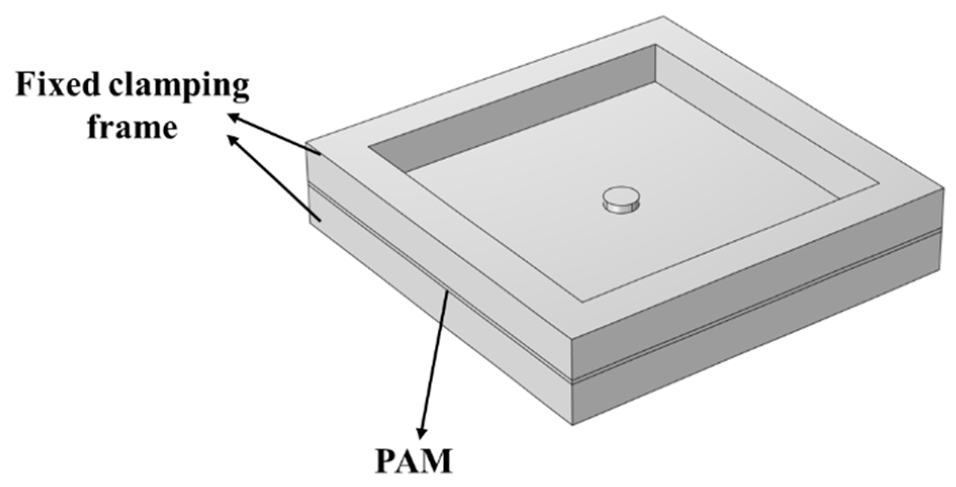
In the MPP+PAM, the design of a single cell of a thin-plate acoustic metamaterial was first performed. As the boundary state of the thin-plate acoustic metamaterial affects the modal characteristics of the resonant system, a clamping device, consisting of two frames of the same size at the top and bottom, was used to fix it, as depicted in Figure 6.
The main parameters of the MPP+PAM included the microperforated plate parameters, relevant parameters of the thin plate and mass block, and depth of the air-back cavity before and after the thin plate. The design resonance frequency was 360 Hz, and the design absorption bandwidth was 300–400 Hz. The design variables and ranges of the values for the MPP+PAM are listed in Table 4.
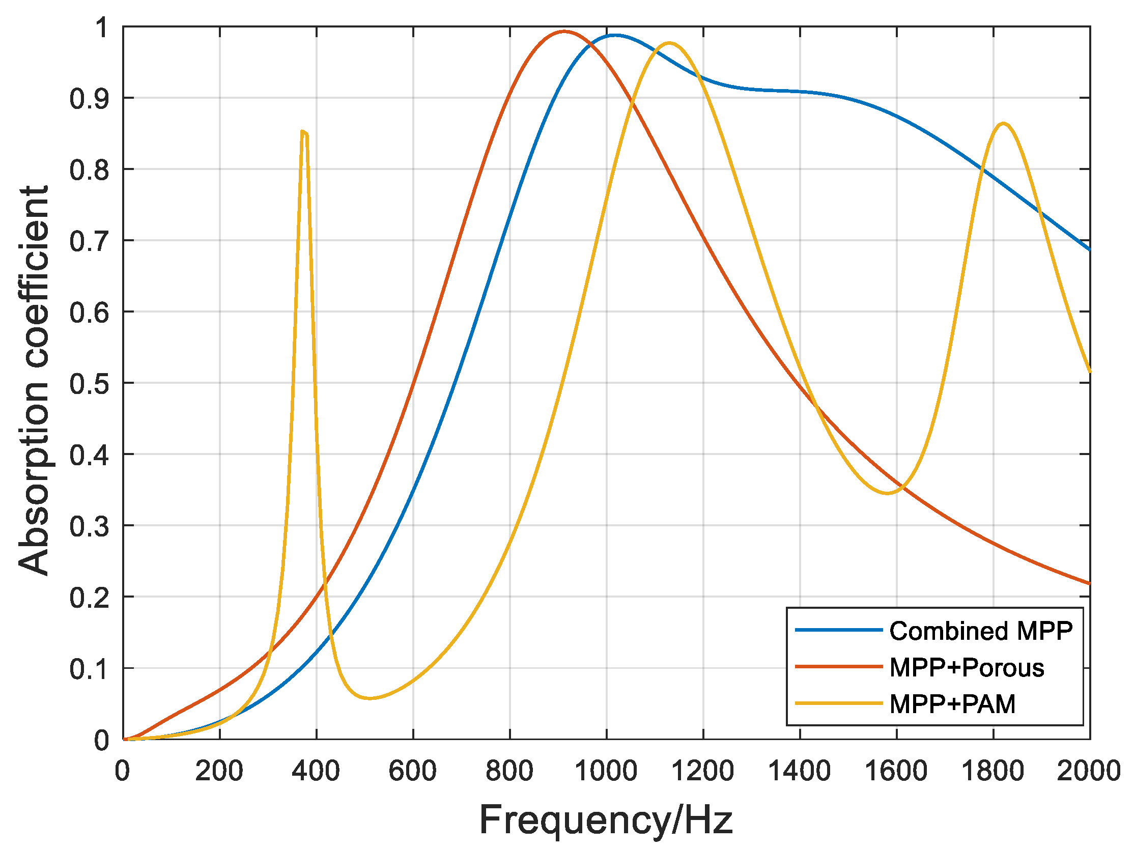
Based on the three composite acoustic structure design parameters, the calculated absorption coefficient curves of the various composite acoustic structures in the frequency range of 0–2000 Hz were plotted, as shown in Figure 7.
As can be seen in Figure 7, the optimized structure exhibits good sound absorption at the designed resonant frequency and in the target frequency band. Under the condition of the positive incidence of sound waves, the peak absorption is close to 1, which is equivalent to the performance of “perfect sound absorbers”. The combined MPP and MPP+Porous have absorption coefficients greater than 0.5 in the 700–1400 Hz range. In contrast, the MPP+PAM produces three absorption peaks through the mutual coupling of the microperforated plate and acoustic metamaterial owing to the introduction of new absorption peaks at low frequencies in the thin plate–mass block system. At the middle and high frequencies, the fourth-order modal resonance of the thin plate–mass block system coupled with the MPP forms a double absorption peak, but the absorption bandwidth becomes narrower. It can be observed that the MPP+PAM achieves acoustic absorption at specific frequencies in the low-frequency band compared with the conventional resonant structure, while retaining the broadband absorption performance of the microperforated plate and thin plate vibration in the middle- and high-frequency bands.

3. Experiment

To further verify the noise reduction effects of the microperforated plate acoustic structures on the helicopter nacelle, experimental studies were conducted in a model helicopter with a complete power unit, transmission system, and fuselage structure.

3.1. Test System

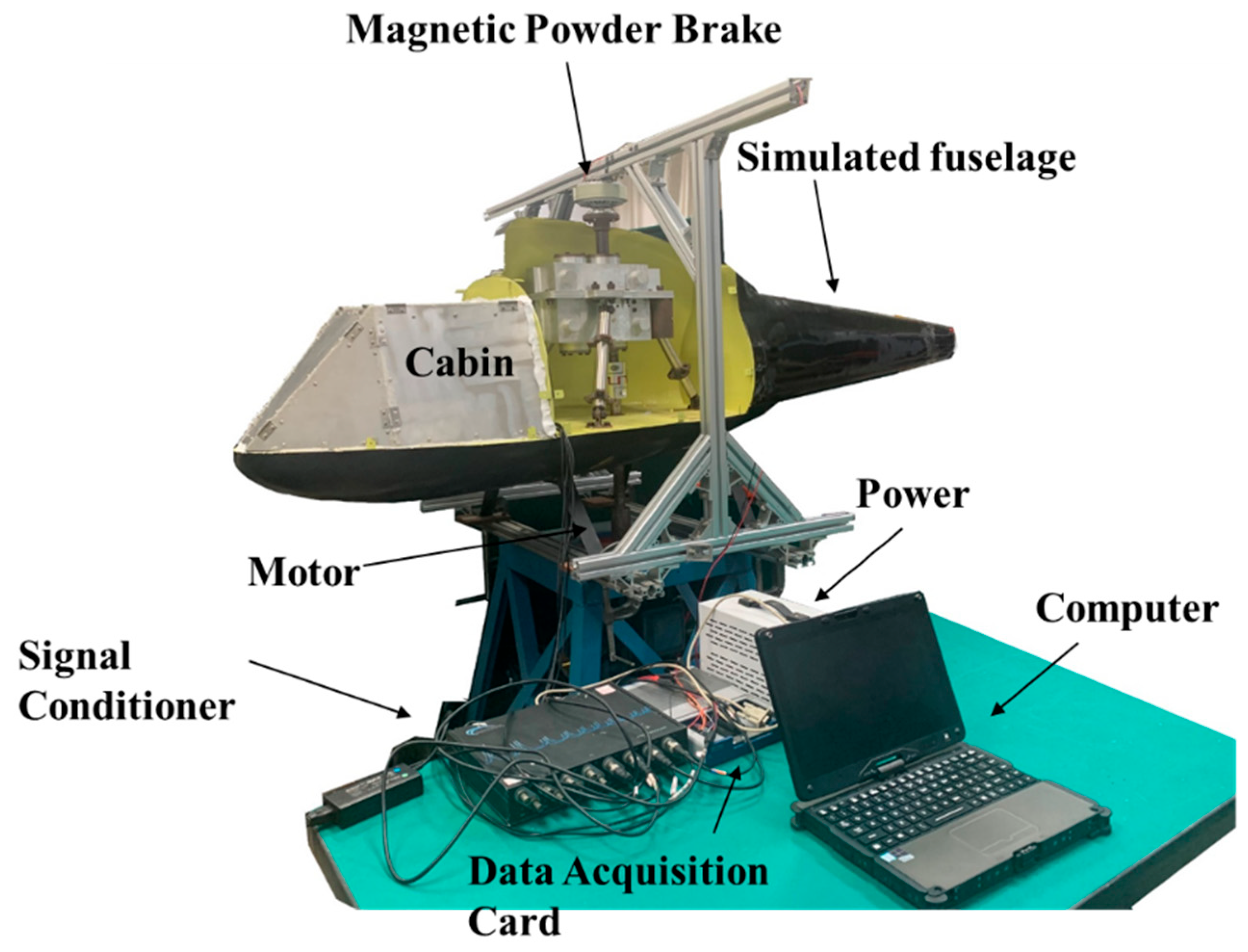
The sound field test system in the cabin of the model helicopter is depicted in Figure 8, and the magnetic powder brake and other measurement and control hardware parameters are listed in Table 5. The test system scheme mainly consisted of the model helicopter, simulated cabin, and measurement and control subsystem. The MPP composite sound absorption structure was installed at the interior trim panel, replacing the original wall panel, and the vibration and noise levels were measured and analyzed before and after installation of the composite acoustic structure.
To facilitate the installation and removal of the MPP composite sound absorption structure, the simulated cabin was divided into six independent double-layer plate structures using fasteners to connect the plates. The interior trim plate was removable to facilitate the installation of the MPP. The back cavity behind the plate was used to fill the porous material and thin-plate-type acoustic supermaterial. The design diagram and physical drawing are displayed in Figure 9.
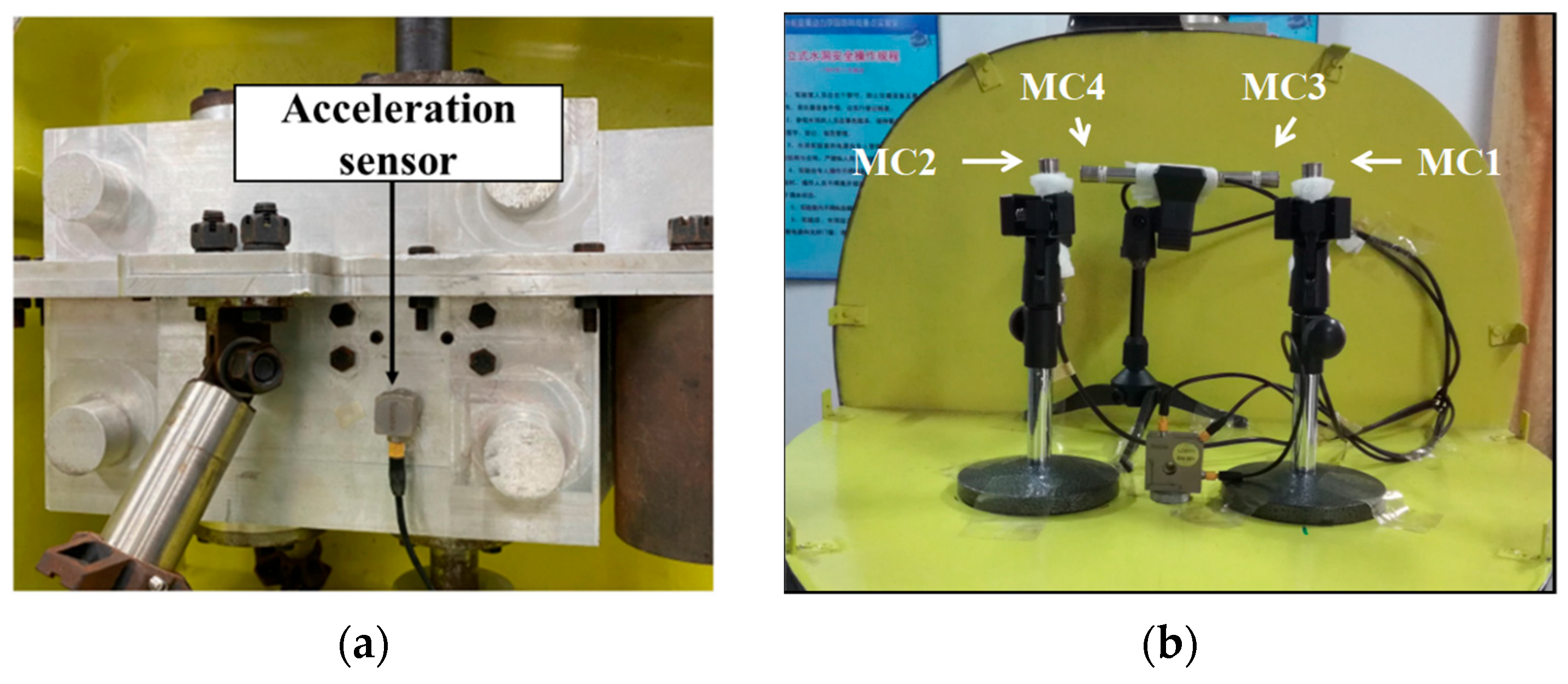
Based on this test system, the operating speed of the motor was set to 900 rpm, and the operating torque of the magnetic powder brake was 6 N·m. A single-axis acceleration sensor was mounted on the main gearbox housing to obtain the main gearbox vibration load spectrum, and four microphones were placed at typical cabin locations to measure the cabin noise level. Microphones 1 and 2 corresponded to the front and co-pilot positions, respectively, whereas microphones 3 and 4 corresponded to the occupant positions. The actual installation positions of each sensor are depicted in Figure 10. The three microperforated composite sound absorption structures and original wall panels were installed in the simulated cabin for testing, and the vibration levels of the main gear housing and sound field in the simulated cabin were measured.

3.2. Vibration Level Test Results

The measured acceleration spectrum in the 0–2000 Hz frequency band of the main reducer housing is shown in Figure 11. In the target frequency band of 500–2000 Hz, the gear meshing frequencies and their harmonic frequencies generated by the main reducer are mainly distributed at 360, 540, 720, 900, 1080, 1350, 1440, and 1800 Hz. In addition to the harmonic components in the design scheme, other frequency components, such as those at 540 Hz and 1350 Hz, also exist; these are crossover and multiplication components owing to gear wear, clearance, and other nonlinear factors.

3.3. Cabin Noise Test Results

3.3.1. Time Domain Analysis

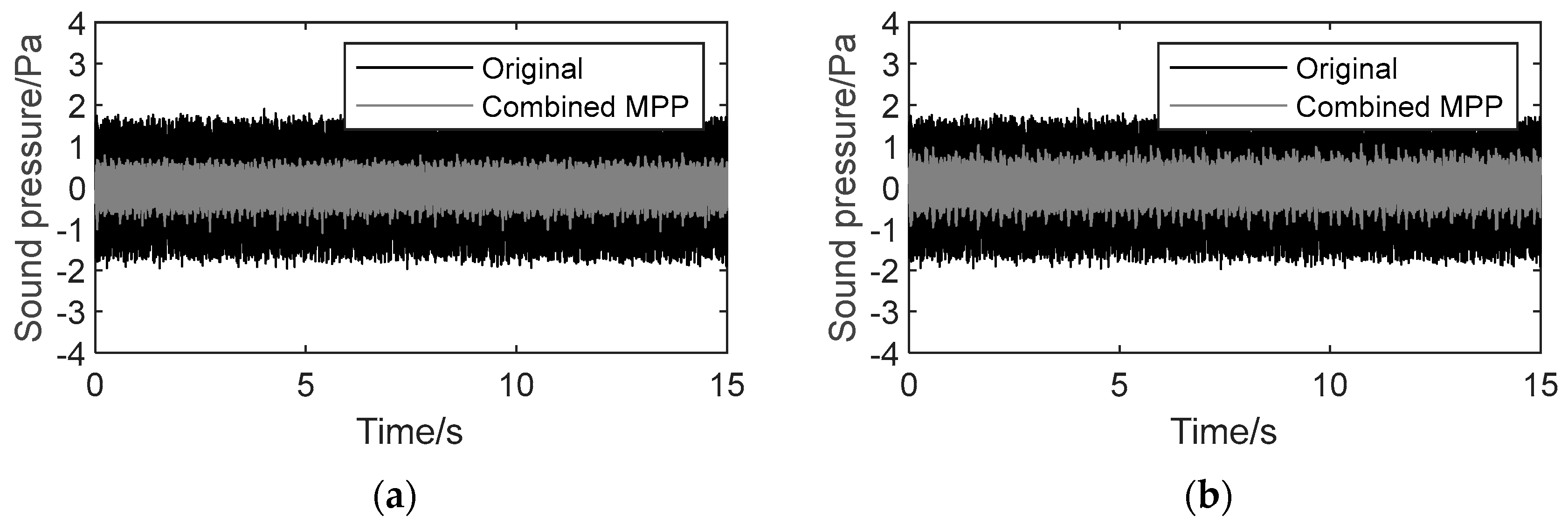
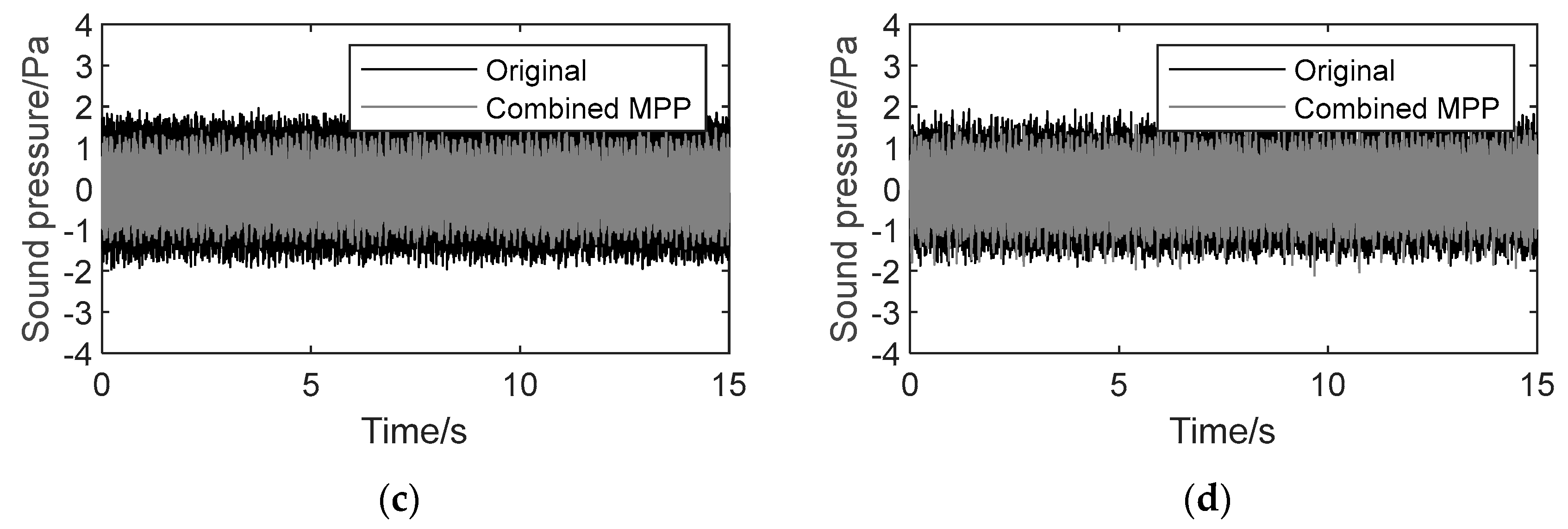
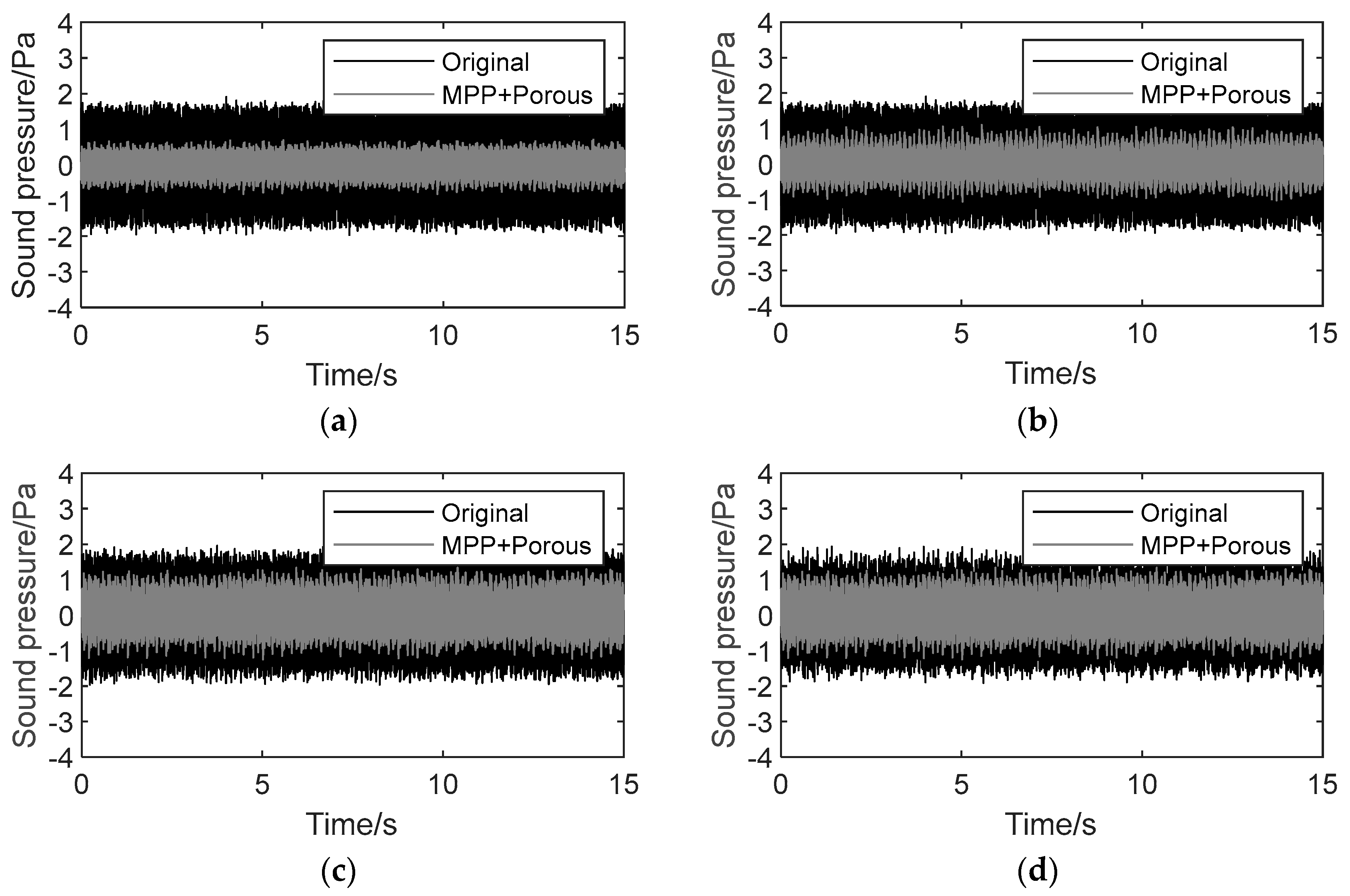
The measured sound pressure values of microphones 1–4, situated at their typical positions in the 0–2000 Hz range in the cabin for 0–15 s, for the three separately installed microperforated plate composite acoustic structures are displayed in Figure 12, Figure 13 and Figure 14. As shown, the sound pressure values at the typical positions in the cabin for all three structures show significant attenuation, and the attenuation effects of microphones 1 and 2 are generally better than those of microphones 3 and 4, which may be due to the closer proximity of microphones 3 and 4 to the noise source.
To reflect the attenuation effect more intuitively, the sound pressure value was converted to SPL using the following equation:
S P L = 20 log ( P e P 0 ) d B
where Pe and P0 are the RMS and standard values of the sound pressure, respectively, and P0 = 2 × 10⁻⁵ Pa.
In the range of 0–2000 Hz, the SPL at the typical position in the cabin where the Combined MPP was installed was attenuated by 2–4 dB. Considering the design frequency range of the Combined MPP, the SPL at the typical position in the range of 500–2000 Hz was obtained using band-pass filtering. In this frequency range, the SPL at each microphone position was attenuated by 9.2 dB on average, which is equivalent to a noise reduction effect of approximately 65%.
In the range of 0–2000 Hz, the SPL at the cabin location where the MPP+Porous structure was installed was attenuated by 2–3 dB. Considering the design frequency range of the MPP+Porous structure, the sound pressure signal in the range of 0–2000 Hz was band-pass-filtered, and the SPL at the typical location in the range of 500–2000 Hz was obtained. In this frequency range, the SPL at each microphone position was attenuated by 8.1 dB on average, equivalent to a noise reduction effect of approximately 61%.
In the range of 0–2000 Hz, the SPL at the cabin location where the MPP+PAM was installed was attenuated by 4.7 dB on average (a noise reduction effect of approximately 42%), because the noise at the engagement frequency of the low-frequency band was effectively controlled.
In summary, all the microperforated plate composite acoustic structures exhibited satisfactory noise suppression effects in the target frequency range.

3.3.2. Frequency Domain Analysis

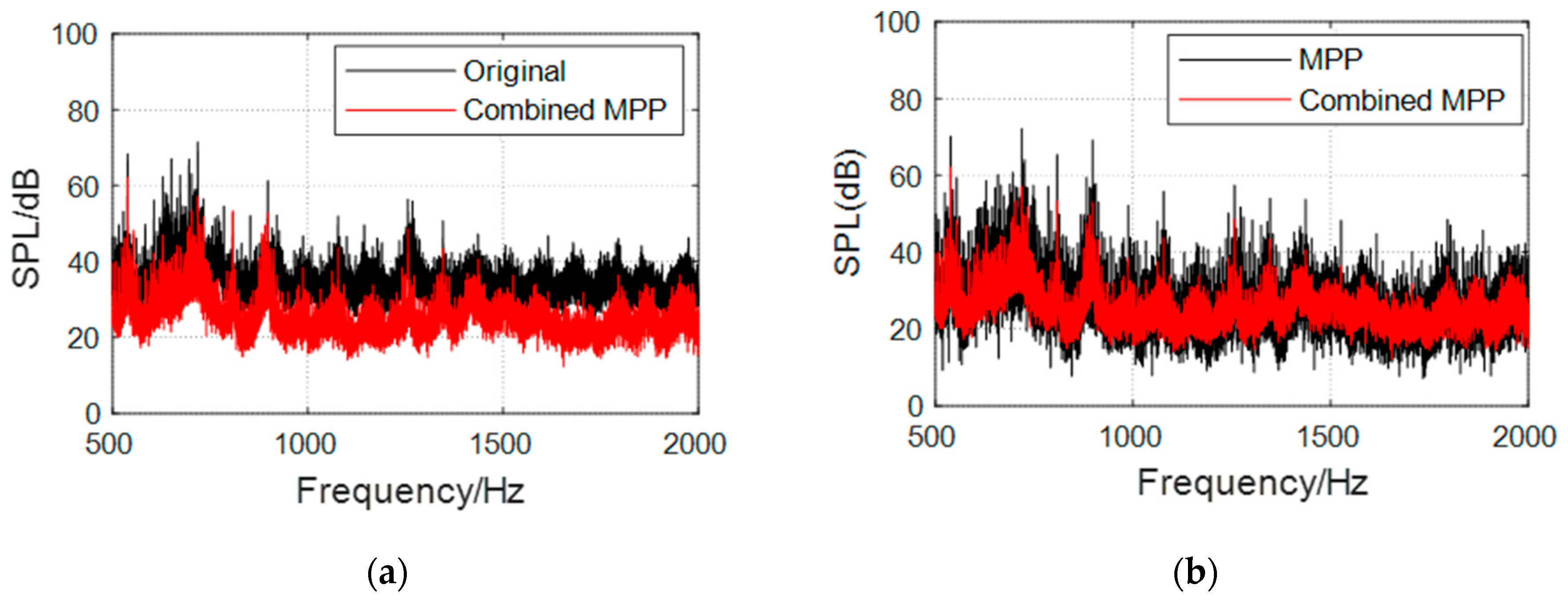
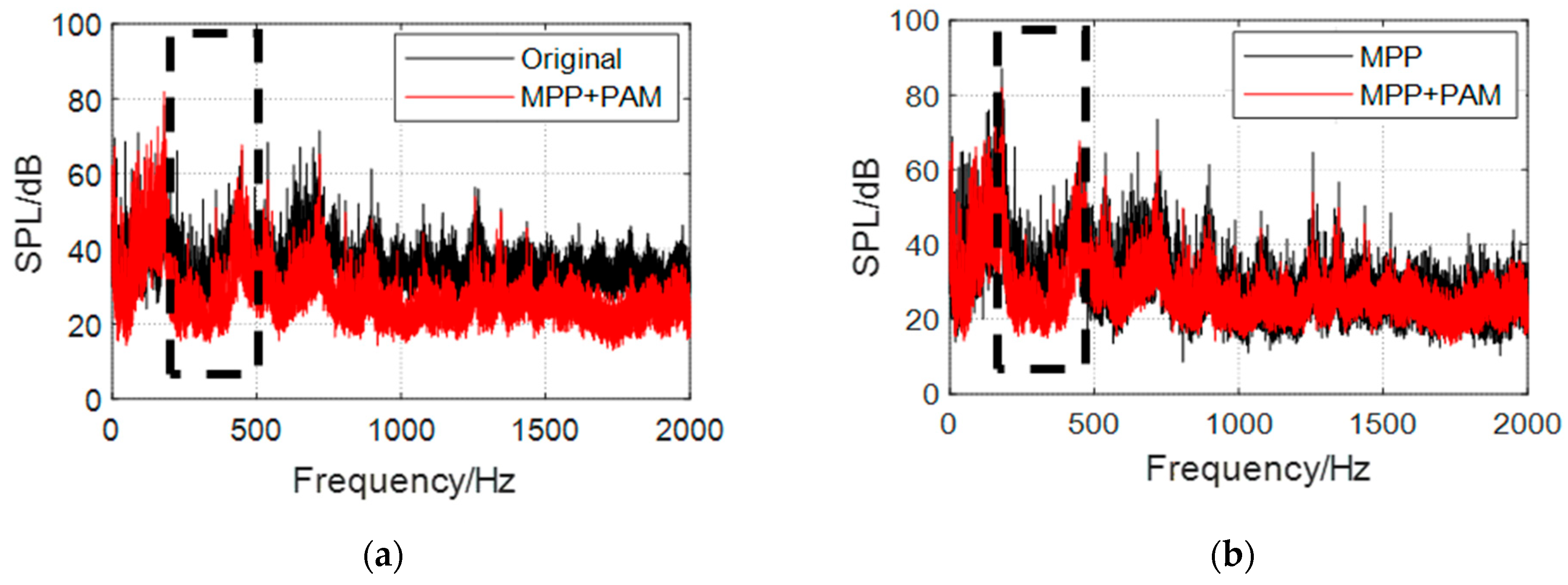
The Fourier transformation of the sound pressure signal in the range of 500–2000 Hz was performed to obtain the SPL spectra at four typical locations in the cabin. To analyze the noise reduction effect in the cabin more intuitively, the SPLs measured at the four typical locations were averaged, and the overall SPL spectrum in the cabin was obtained, as shown in Figure 15, Figure 16 and Figure 17.
Observing the frequency response curve in each figure, the following can be observed:
  • Compared with the original wall panel, the three structures evidently attenuate the cabin SPL in the range of the resonance peak and its nearby frequency band, with a maximum attenuation greater than 20 dB.
  • Owing to the influence of the diffusion sound field, a new sound absorption band is formed, and the SPL with the three structures is attenuated by 10 dB, on average, over a wide frequency range of 1300–2000 Hz. The overall cabin noise level is effectively controlled.
  • The MPP+PAM attains a significant cabin SPL attenuation in the range of 300–450 Hz, with an average noise reduction effect of 45%. It also achieves a good low-frequency sound absorption effect and maintains satisfactory broadband noise reduction effects in the middle- and high-frequency bands.
  • Compared with the sound absorption performance of the ordinary MPP, those of the three structures are optimized to a certain extent. The Combined MPP substantially improves the sound absorption performance in the 600–1100 Hz and 1400–1800 Hz ranges. The MPP+Porous structure enhances the sound absorption performance in the range of 600–1200 Hz. The reason for the weak optimization effect of the porous material here is that this material needs to have a certain thickness to obtain the best sound absorption performance. After coupling with the MPP, the sound absorption performance is only significantly optimized near the resonance frequency. The sound absorption performance of the MPP+PAM is considerably improved in the 300–450, 600–900, and 1600–1800 Hz ranges.
The Combined MPP and MPP+Porous structure target middle- and high-frequency band noise. The Combined MPP is suitable for multiline spectrum middle- and high-frequency noise scenarios with restricted use space; however, the processing difficulty of multiple perforations is high. The MPP+Porous structure is appropriate for single-line-spectrum noise scenarios with larger use space. It has a simple process and lightweight material and can also be used with the Combined MPP if the sound absorption band needs to be broadened. The MPP+PAM is suitable for broadband noise scenarios; however, it is expensive and difficult to process, considering the additional weight of the fixtures, preparation of the thin plates and mass blocks, and other constraints.
In summary, the three proposed MPP composite sound absorption structures meet the design requirements and can effectively reduce the cabin noise level according to different target frequency bands, with good broadband noise reduction characteristics.

4. Simulation

4.1. Simulation Object

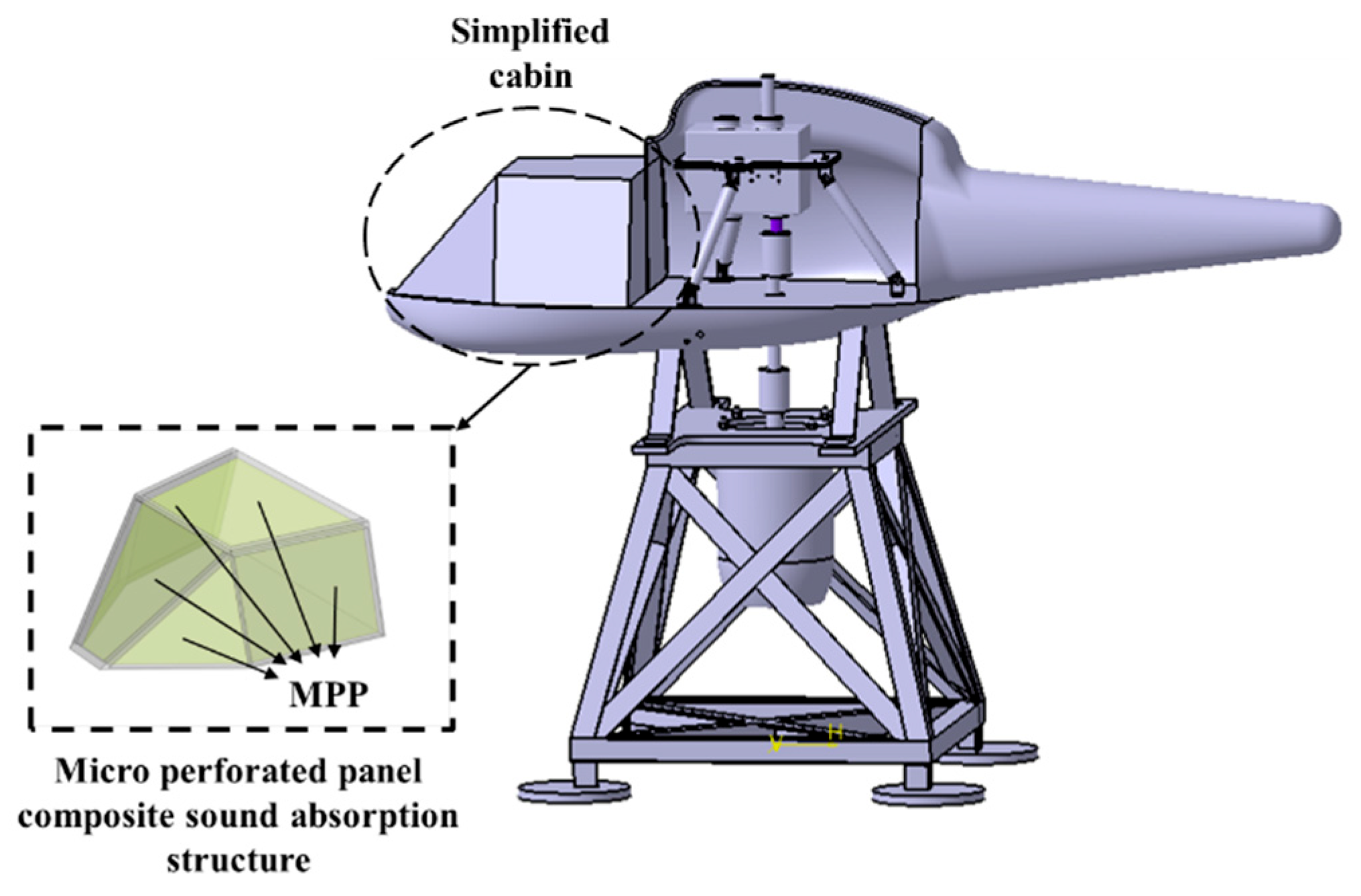
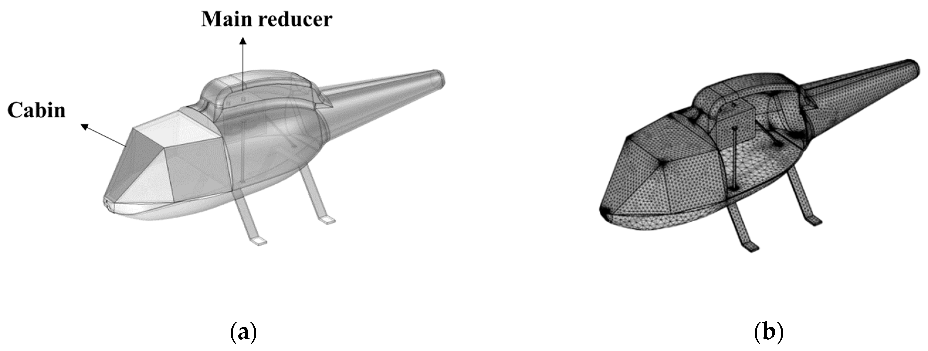
To conduct a simulation study of the sound field in the cabin of the model helicopter, the nacelle of the helicopter was selected as the simulation object. Figure 18 illustrates the nacelle structure of the model helicopter, whose fuselage length, width, and height are 2065, 580, and 564 mm, respectively. The model was designed based on a light helicopter shape and reducer arrangement. The fuselage structure was supported by the landing gear and fixed on the table structure. To reduce the processing difficulty, the nacelle was simplified into a polyhedral configuration, and the MPP was fixed on the helicopter nacelle wall plate, leaving an air-back cavity of appropriate thickness. Porous materials and acoustic supermaterials were introduced to form a composite acoustic structure. By designing reasonable structural parameters, the resonant frequency and sound absorption band of the composite MPP acoustic structure were adjusted to obtain a better noise-reduction effect.

4.2. Main Reducer Vibration Source Simulation

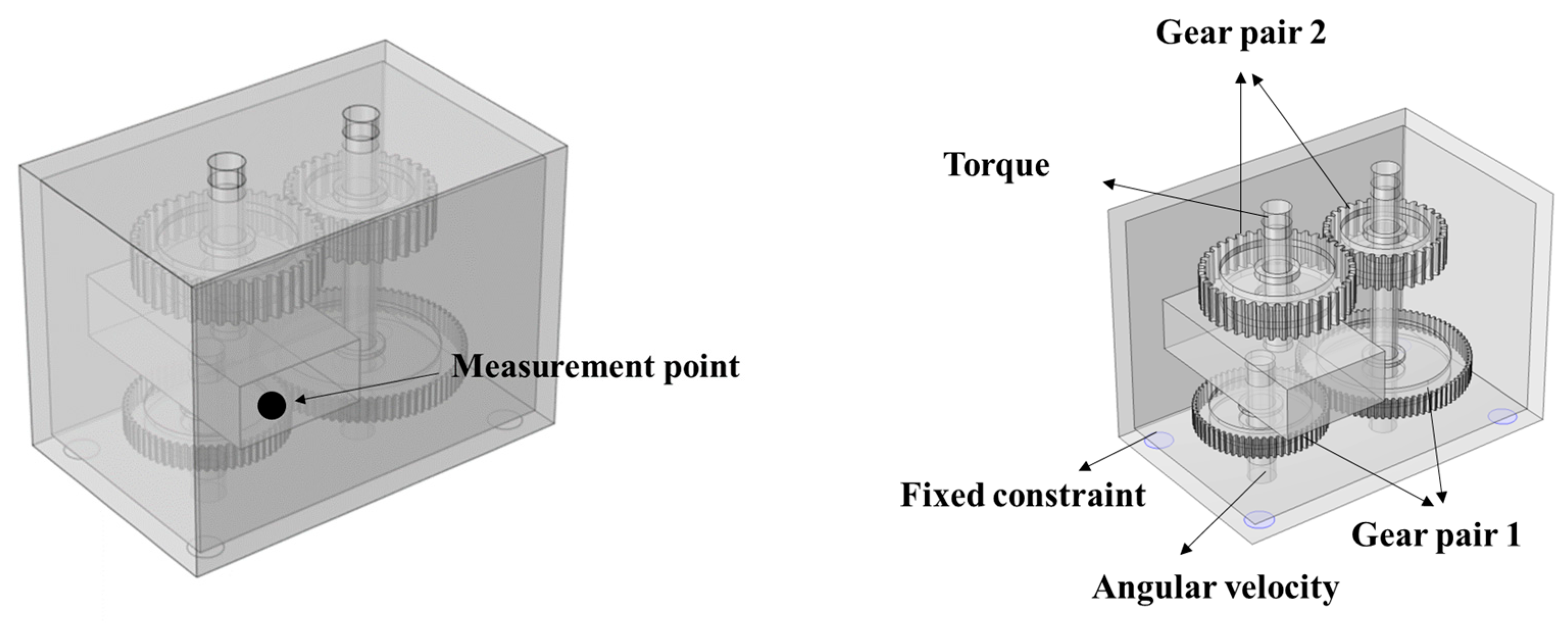
A dynamic model of the main gearbox was established to simulate the noise in the helicopter cabin caused by the main gearbox more realistically. Based on the physical parameters of the main gearbox in the cockpit of the model helicopter, the main gearbox dynamic model was constructed using finite element software, as shown in Figure 19. The length, width, and height of the main gearbox model were 250, 160, and 180 mm, respectively. The internal gearbox included two pairs of gears, with 60 and 32 teeth for the main wheel and 80 and 40 teeth for the driven wheel and a transmission ratio of 4/3. In the simulation process, the acceleration of the hinged joint of the input shaft is set to simulate the loading of the motor, the process of the hinged joint of the output shaft is set to simulate the loading of the motor, and the reaction torque of the rotor is set as “fixed constraints” at the bottom four corners of the shell.
In the multibody dynamic physical field, the transient response of the main reducer dynamic model was calculated, and a measurement point on the outer casing of the primary active wheel was selected to derive the average acceleration response curve in the frequency range of 0–2000 Hz on the main reducer casing, as displayed in Figure 20. When the power input shaft speed was 900 rpm, the gear meshing frequencies and their harmonic frequencies generated by the main reducer in the frequency range of 0–2000 Hz were mainly distributed at 360, 720, 900, 1080, 1440, and 1800 Hz, which indicates that the main gear dynamic model can better simulate the vibration excitation environment of the main gear of the helicopter.
Furthermore, the main gear model was combined with the nacelle model through the spar. The dynamic response of the model nacelle was then simulated and calculated in the multibody dynamic physical field under the condition of the main gear’s vibration excitation, which was used for the subsequent acoustic field simulation calculation of the pressure acoustic physical field. The grid used in the model was a free tetrahedral grid cell. Because the maximum frequency of the analysis in this study was 2000 Hz, the grid cell size could be no larger than one-sixth of the wavelength. Therefore, the size of the grid cell was set to 28 mm, and fixed constraints were applied to the bottom of the landing gear. The main gear input shaft speed was set to 900 rpm, and the main gear output shaft torque was 6 Nm. Figure 21 shows the geometric model and its meshing.

4.3. Model Cabin Sound Field Simulation

In this study, three MPP acoustic structures for noise reduction in the cabin of a model helicopter were developed. For comparison and verification, cabin sound field simulations were carried out for two cabin wall panels with and without MPP acoustic structures to obtain the sound pressure level (SPL) distribution in the cabin and analyze the cabin noise reduction characteristics of the MPP acoustic structures.
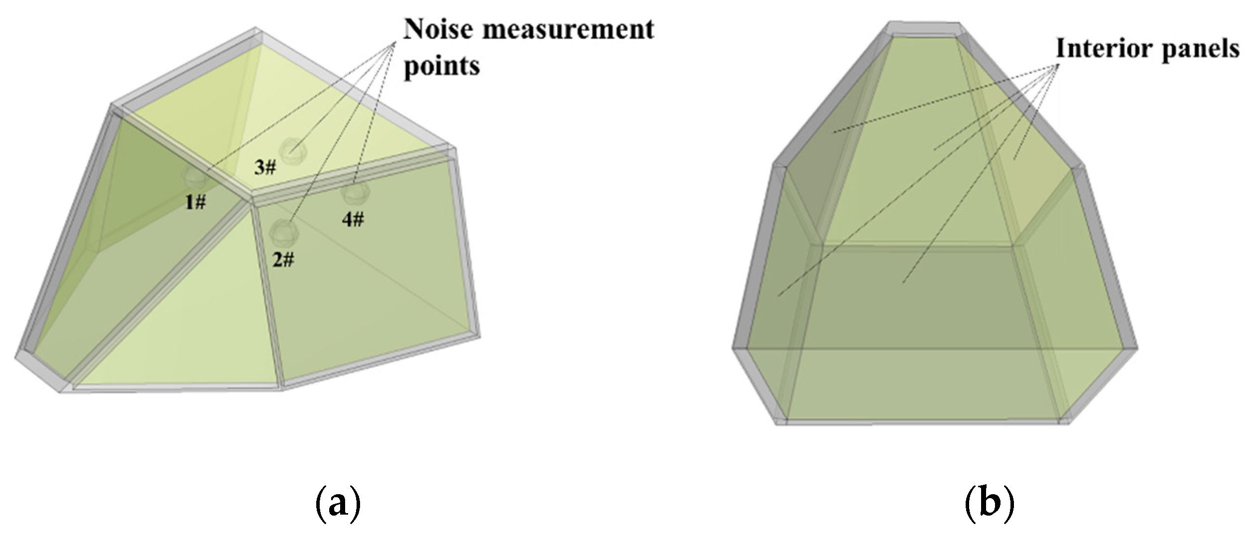
Based on the vibration response of the wall plate under real gear meshing conditions obtained from the vibration source’s simulation, the vibration acceleration responses of the back and bottom plates of the nacelle were used as the noise radiation source in the acoustic pressure field, employing a generalized stretching operator that mapped the values from the source end to the target end. Figure 22 illustrates the nacelle simulation model, where the helicopter nacelle consists of an external skin, an interior trim panel, and back and bottom plates as radiation sources. Four spherical domains within the model were used to simulate the human ear position of the occupants and thus measure the noise signal at typical locations within the cabin. The noise reduction characteristics of the cabin equipped with the microperforated composite acoustic structure on the interior panel were analyzed by comparing the two cases with the original wall panel.
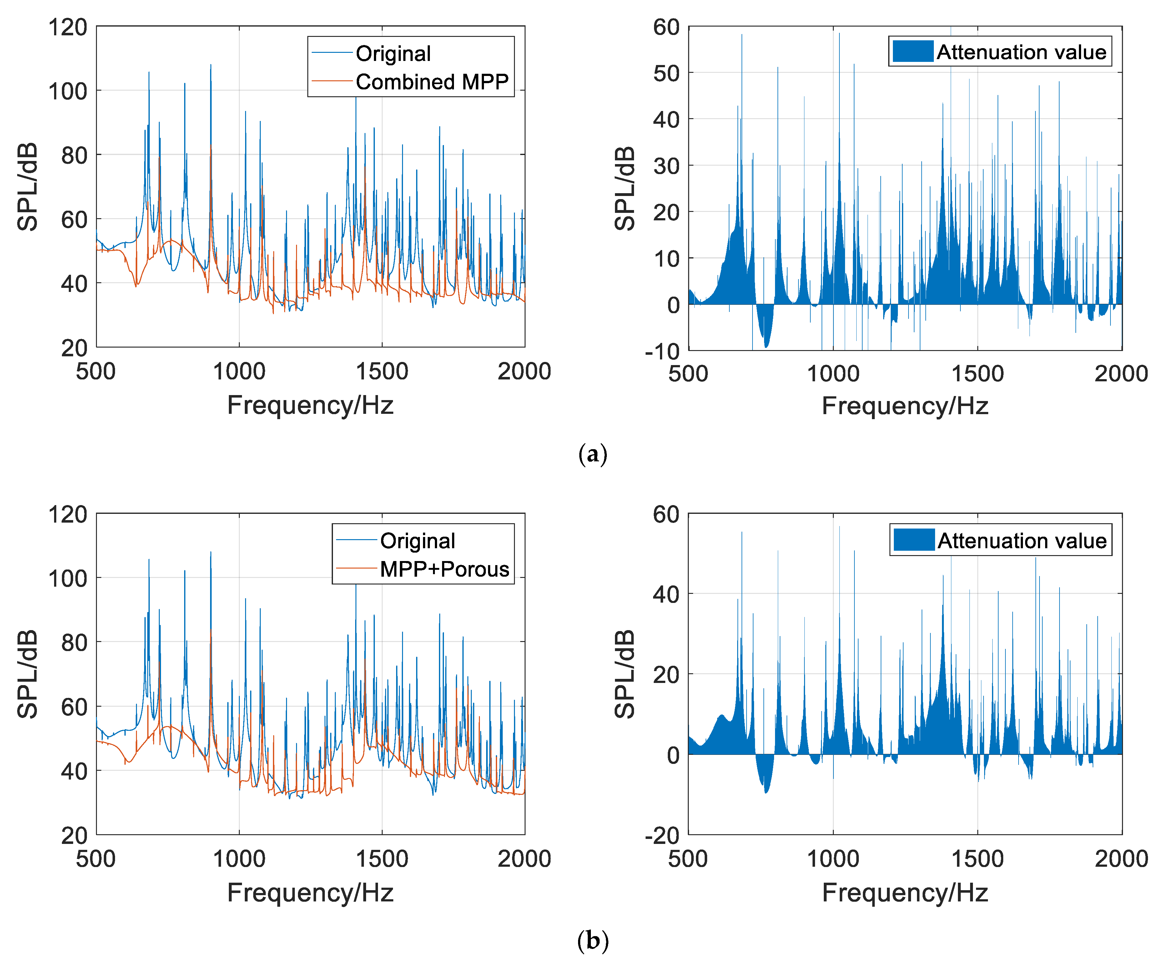
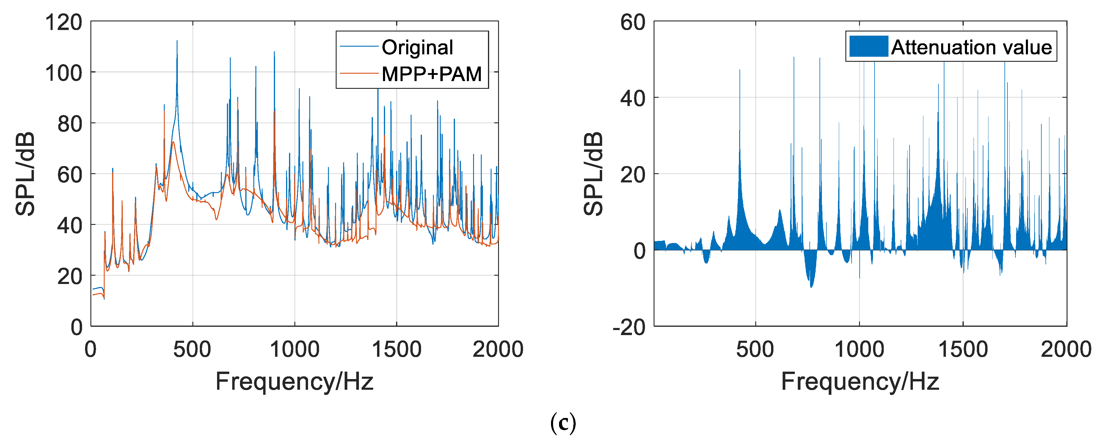
Through a pressure acoustic frequency domain simulation analysis, the SPL data of four typical measurement points in the cabin were acquired, and a weighted average was calculated to obtain the average SPL frequency response curve, as displayed in Figure 23.
As shown in Figure 23, the average SPLs of the four measurement points in the cabin, after installing the composite microperforated plate acoustic structures, are attenuated to different degrees in the target frequency band range. Among them, the average SPL in the cabin with the Combined MPP (Figure 23a) is significantly attenuated in the frequency ranges of 500–1000 Hz and 2300–2000 Hz. The attenuation values are 10.9, 24.9, 7.2, and 10.4 dB at the four engagement frequencies of 720, 900, 1080, and 1440 Hz, respectively. The average SPL in the cabin with the MPP+Porous structure (Figure 23b) is substantially attenuated in the 500–1000 Hz and 2300–2000 Hz bands, with 15.3, 24.1, 6.4, and 11.9 dB attenuation at the four engagement frequencies of 720, 900, 1080, and 1440 Hz, respectively. The average SPL in the cabin with the MPP+PAM (Figure 23c) is considerably attenuated in the frequency ranges of 350–500, 2300–1500, and 1700–2000 Hz, with 4.3, 23.4, and 11.3 dB attenuation at the three engagement frequencies of 360, 900, and 1440 Hz, respectively. The three MPP composite sound absorption structures controlled the cabin noise in the target frequency range to a satisfactory degree.
Comparing the experimental and simulation prediction results, it is not difficult to find that there are certain differences. The main reason for the error is that the simulation only considers the structural sound transmission and ignores the air sound transmission, while both exist simultaneously in the test. However, the trend of the overall SPL frequency response curves in the simulation and test results are basically the same, and the peaks and valleys of the engagement fundamental frequency and its harmonic frequency are obvious, mostly distributed around 40–60 dB. There is only an error in the SPL amplitude, which has less influence on the prediction of the structure noise reduction performance during simulation. Therefore, the simulation results can verify the effectiveness and practicality of the microperforated panel composite sound absorption structure for noise control in helicopter cabins.

5. Conclusions

In this paper, according to the real helicopter cabin noise, based on the sound absorption structure of microperforated panels, porous materials and acoustic metamaterials are introduced. Simulation and experimental studies of noise suppression in helicopter cabins based on the composite acoustic structures of the microperforated panels were conducted to verify their feasibility and effectiveness. The main conclusions are as follows:
  • The proposed MPP composite sound absorption structures can suppress the noise from the main gearbox in the target frequency band to a satisfactory degree.
  • Based on the constructed finite element model of the helicopter main gear/body acoustic vibration coupling, the in-cabin noise reduction characteristics of the composite microperforated plate acoustic structures were obtained via simulation analysis. The simulation results show that the Combined MPP and MPP+Porous structure significantly improve the acoustic bandwidth and acoustic performance and can effectively reduce the cabin noise level in the range of 500–2000 Hz, with an attenuation amplitude of up to 35 dB. The MPP+PAM achieves low-frequency noise control in the range of 350–450 Hz and has a certain noise control effect in the middle- and high-frequency ranges.
  • Based on the constructed model helicopter test platform, the cabin sound field conditions of composite acoustic structures equipped with microperforated panels were tested under real main gear vibration excitation. The cabin sound fields were compared with that of the original wall panel to verify the cabin noise reduction characteristics of the composite MPP acoustic structures. The test results show that the Combined MPP and MPP+Porous structure realize an overall cabin SPL attenuation of 8–10 dB, on average, in a wide frequency range of 500–2000 Hz, with an amplitude of more than 20 dB. The MPP+PAM achieves low-frequency sound absorption in the frequency range of 300–450 Hz; the sound absorption effect reaches 45%, and it also has good noise reduction effects in the middle- and high-frequency bands.

Author Contributions

Conceptualization, Y.L. and C.L. (Chunbo Lan); Methodology, C.L. (Chenglei Li); Software, C.L. (Chenglei Li); Formal analysis, Y.W.; Writing—original draft, C.L. (Chenglei Li); Project administration, Y.L. All authors have read and agreed to the published version of the manuscript.

Funding

This research received no external funding.

Institutional Review Board Statement

Not applicable.

Informed Consent Statement

Informed consent was obtained from all subjects involved in the study.

Data Availability Statement

Not applicable.

Conflicts of Interest

The authors declare no conflict of interest.

References

  1. Yu, Y.H. Rotor blade-vortex interaction noise. Prog. Aerosp. Sci. 2000, 36, 97–115. [Google Scholar] [CrossRef]
  2. Scheidler, J.J. A review of noise and vibration control technologies for rotorcraft transmissions. In Proceedings of the INTER-NOISE and NOISE-CON Congress, Hamburg, Germany, 21–24 August 2016; Institute of Noise Control Engineering: Hamburg, Germany, 2016; Volume 253, pp. 2986–2997. [Google Scholar]
  3. Szefi, J.T. Helicopter Gearbox Isolation Using Periodically Layered Fluidic Isolators. Ph.D. Thesis, The Pennsylvania State University, State College, PA, USA, 2003. [Google Scholar]
  4. Ma, X.; Lu, Y.; Wang, F. Active structural acoustic control of helicopter interior multifrequency noise using input-output-based hybrid control. J. Sound Vib. 2017, 405, 187–207. [Google Scholar] [CrossRef]
  5. Millott, T.A.; Yoerkie, C.A.; Welsh, W.A.; MacMartin, D.G.; Davis, M.W. Flight test of active gear-mesh noise control on the S-76 aircraft. In Proceedings of the American Helicopter Society 54th Annual Forum, Washington, DC, USA, 20–22 May 1998; The American Helicopter Society Inc.: Fairfax, VA, USA, 1998. [Google Scholar]
  6. Caillet, J.; Marrot, F.; Unia, Y.; Aubourg, P.-A. Comprehensive approach for noise reduction in helicopter cabins. Aerospa. Sci. Technol. 2012, 23, 17–25. [Google Scholar] [CrossRef]
  7. Ang LY, L.; Tran LQ, N.; Phillips, S.; Koh, Y.K.; Lee, H.P. Low-frequency noise reduction by earmuffs with flax fibre-reinforced polypropylene ear cups. Adv. Acoust. Vib. 2018, 2018, 2057820. [Google Scholar] [CrossRef] [Green Version]
  8. Sakagami, K.; Morimoto, M.; Yairi, M. Application of microperforated panel absorbers to room interior surfaces. Int. J. Acoust. Vib. 2008, 13, 120–124. [Google Scholar]
  9. Zha, X. Transparent micro-perforated sound-absorbing material improves the sound quality of the newly built parliament hall. Acoust. Technol. 1994, 13, 1–3. [Google Scholar]
  10. Mao, D.; Xia, J.; Hong, Z. Study on sound barrier based on micro-perforated panel structure with top absorbing cylinder. Acoust. Technol. 1999, 18, 26–29. [Google Scholar]
  11. Li, L.; Zhang, Z.; Huang, Q.; Li, S. A sandwich anechoic coating embedded with a micro-perforated panel in high-viscosity condition for underwater sound absorption. Compos. Struct. 2019, 235, 111761. [Google Scholar] [CrossRef]
  12. Wu, Q.; Liu, Y.; Li, Y.; Tan, L.; Yi, C. Simulation Study on Acoustic Performance of Ventilation Muffler of STC-GV Supercharger. Machinery 2021, 48, 8–13+19. [Google Scholar]
  13. Lee, W.Y.; Kim, J.C.; Noh, H.M. Application of a micro-perforated panel absorber to reduce the curve squeal noise of railways. Noise Control. Eng. J. 2021, 69, 507–517. [Google Scholar] [CrossRef]
  14. Chen, H. Research on Noise Reduction Method of Micro-Perforated Web Face Gear Transmission Based on Helmholtz Theory. Master’s Thesis, Nanjing University of Aeronautics and Astronautics, Nanjing, China, 2015. [Google Scholar]
  15. Markandan, K.; Lim, R.; Kumar Kanaujia, P.; Seetoh, I.; Bin Mohd Rosdi, M.R.; Huey Tey, Z.; Seng Goh, J.; Cheong Lam, Y.; Lai, C. Additive manufacturing of composite materials and functionally graded structures using selective heat melting technique. J. Mater. Sci. Technol. 2020, 47, 243–252. [Google Scholar] [CrossRef]
  16. Shen, J.; Lee, H.P.; Yan, X. Sound absorption performance and mechanism of flexible PVA microperforated membrane. Appl. Acoust. 2022, 185, 108420. [Google Scholar] [CrossRef]
  17. Liu, C.R.; Wu, J.H.; Yang, Z.; Ma, F. Ultra-broadband acoustic absorption of a thin microperforated panel metamaterial with multi-order resonance. Compos. Struct. 2020, 246, 112366. [Google Scholar] [CrossRef]
  18. Yan, S.; Wu, J.; Chen, J.; Mao, Q.; Zhang, X. Design of Honeycomb Microperforated Structure with Adjustable Sound Absorption Performance. Shock. Vib. 2021, 2021, 6613701. [Google Scholar] [CrossRef]
  19. Maa, D.-Y. Wide-Band sound absorber based on microperforated panels. Chin. J. Acoust. 1985, 3, 3–14. [Google Scholar]
  20. Maa, D.-Y. Theory and Design of Microperforated Panel Sound-Absorbing Constructions. Sci. Sin. 1975, 18, 55–71. [Google Scholar]
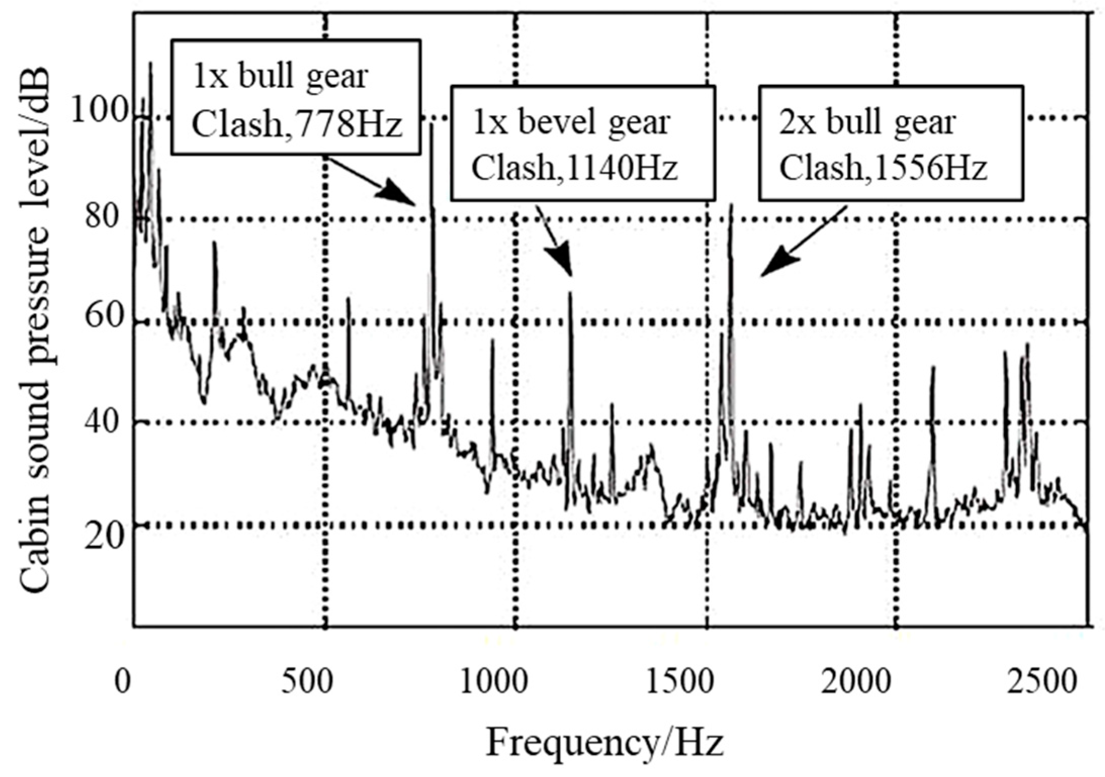
Figure 1. Noise spectrum of an S-76 helicopter cabin.
Applsci 13 08153 g001
Figure 2. Helicopter cabin wall panel structure. (a) Model 1. (b) Model 2.
Applsci 13 08153 g002
Figure 3. Schematic of the three MPP composite sound absorption structures: (a) Combined MPP; (b) MPP+Porous; (c) MPP+PAM.
Applsci 13 08153 g003
Figure 4. Schematic of the MPP acoustic structure for helicopter cabin wall panels (the perforations are enlarged for illustration).
Applsci 13 08153 g004
Figure 5. Schematic of the thin-plate acoustic metamaterial.
Applsci 13 08153 g005
Figure 6. Schematic of the PAM clamping device.
Applsci 13 08153 g006
Figure 7. Sound absorption coefficient curves.
Applsci 13 08153 g007
Figure 8. Model helicopter test system.
Applsci 13 08153 g008
Figure 9. Physical diagram of the simulated cabin and sample structure. (a) Design diagram. (b) Physical diagram (Combined MPP). (c) Physical diagram (MPP+Porous back cavity). (d) Physical diagram (MPP+PAM back cavity).
Applsci 13 08153 g009
Figure 10. Measuring sensor mounting position. (a) Acceleration sensor. (b) Microphones.
Applsci 13 08153 g010
Figure 11. Main reducer housing acceleration response spectrum.
Applsci 13 08153 g011
Figure 12. Sound pressure values at typical locations in the cabin (Combined MPP). (a) Microphone 1. (b) Microphone 2. (c) Microphone 3. (d) Microphone 4.
Applsci 13 08153 g012aApplsci 13 08153 g012b
Figure 13. Sound pressure values at typical locations in the cabin (MPP+Porous). (a) Microphone 1. (b) Microphone 2. (c) Microphone 3. (d) Microphone 4.
Applsci 13 08153 g013
Figure 14. Sound pressure values at typical locations in the cabin (MPP+PAM). (a) Microphone 1. (b) Microphone 2. (c) Microphone 3. (d) Microphone 4.
Applsci 13 08153 g014aApplsci 13 08153 g014b
Figure 15. Comparison of the overall noise in the cabin before and after the installation of the Combined MPP. (a) Original. (b) MPP.
Applsci 13 08153 g015
Figure 16. Comparison of the overall noise in the cabin before and after the installation of the MPP+Porous structure. (a) Original. (b) MPP.
Applsci 13 08153 g016
Figure 17. Comparison of the overall noise in the cabin before and after the installation of the MPP+PAM. (a) Original. (b) MPP.
Applsci 13 08153 g017
Figure 18. Schematic of the model helicopter.
Applsci 13 08153 g018
Figure 19. Main reducer dynamic model.
Applsci 13 08153 g019
Figure 20. Average acceleration frequency response curve of the main reducer housing.
Applsci 13 08153 g020
Figure 21. Finite element model of the helicopter. (a) Geometric model. (b) Finite element mesh.
Applsci 13 08153 g021
Figure 22. Cabin geometry model. (a) Noise measurement points. (b) Interior trim panels.
Applsci 13 08153 g022
Figure 23. Average SPL frequency response curve in the cabin equipped with different MPP composite sound absorption structures (compared with the original wall plate). (a) Combined MPP. (b) MPP+Porous. (c) MPP+PAM.
Applsci 13 08153 g023aApplsci 13 08153 g023b
Table 1. Parameters of melamine sponge.
Parametersσ (N·s·m-4)ϕαΛ (μm)Λ′ (μm)
Numerical value10,5000.9951.0059240470
Table 2. Combined MPP design parameters.
StructureParametersNumerical ValueParametersNumerical Value
Combined MPPPore size d10.40 mmPerforation rate p12.88%
Pore size d20.57 mmPerforation rate p20.94%
Plate thickness t1.00 mmDorsal cavity depth D20 mm
Table 3. MPP+Porous structure design parameters.
StructureParametersNumerical ValueParametersNumerical Value
MPP+PorousPore size d0.52 mmPerforation rate p1.11%
Plate thickness t1.00 mmDorsal cavity depth D20 mm
Note: For the melamine sponge parameters, refer to Table 1.
Table 4. MPP+PAM design parameters.
StructureParametersNumerical ValueParametersNumerical Value
MPP+PAMPore size d0.53 mmPerforation rate p0.96%
Depth of cavity in front of thin plate D110 mmDepth of cavity behind thin plate D210 mm
Thin plate thickness tp0.2 mmThin plate length B50 mm
Table 5. Test system equipment models and their parameters.
EquipmentMode
Magnetic powder brakePB-B2-0.6
Acceleration sensorLC0119
Microphone378B11
Signal conditionerCM3508
Data collectorNI USB6343
Disclaimer/Publisher’s Note: The statements, opinions and data contained in all publications are solely those of the individual author(s) and contributor(s) and not of MDPI and/or the editor(s). MDPI and/or the editor(s) disclaim responsibility for any injury to people or property resulting from any ideas, methods, instructions or products referred to in the content.