Article

Effects of Diagonal Friction Dampers on Behavior of a Building

Civil Engineering Department, Faculty of Technology, Sakarya University of Applied Sciences, Sakarya 54187, Türkiye
*
Author to whom correspondence should be addressed.
Appl. Sci. 2023, 13(14), 8311; https://doi.org/10.3390/app13148311
Submission received: 15 May 2023 / Revised: 4 July 2023 / Accepted: 13 July 2023 / Published: 18 July 2023

Abstract

:
In this study, the effect of the friction damper location on the earthquake behavior of a building was investigated. Diagonal braced friction dampers were placed on different floors, and the changes in building behavior were examined. For this purpose, a scaled experimental building model with five floors, with a single span in the x and y directions, was used. Numerical model validation was carried out by taking into account the experimental and numerical period values obtained via the effect of free vibration. The period, peak displacement, and maximum shear force of the friction dampers, arranged in various configurations, were compared using the numerical model in conjunction with three different earthquake acceleration records. According to the investigations, the damper performance of the design changes depending on the earthquake acceleration that is affecting the building. Friction dampers located on the lower floors are more effective at reducing period, peak displacement, and floor shear forces than those located on the upper floors.

1. Introduction

Buildings experience varied earthquake forces and translations depending on the weight and stiffness of each floor. In cases whereby the displacements exceed the design limits, the deformations cause damage to the structures. Eccentrically, centrically fused, and concentrically braced frames are types of cross used to prevent horizontal movement [1,2,3]. In addition, these friction dampers, developed to limit horizontal drift, are types of passive energy absorbers used to prevent damage caused by earthquakes or design errors [4]. Although friction dampers were first designed by taking the braking system used in automobiles as an example, they have shown various developments over the years [5,6].
If most of the seismic energy can be damped mechanically, the response of the structure can be controlled without structural damage. In friction dampers, the energy coming into the structure is absorbed by converting it from kinetic energy to heat energy via friction. Thus, inelastic behavior that causes permanent damage to the structure is prevented. This prevents negative situations such as repair costs, service disruptions in important buildings such as hospitals, schools, etc., and loss of time. Frictional dampers increase the stiffness of the structure, together with the damping contribution they provide to the structure. The ductility of the structure depends on the amount of energy that the structural elements can absorb during their inelastic behavior, such as bending, buckling, and torsion [7]. The ductility of the structure increases with the effect of friction [8]. Wang et al. proposed a buckling plate self-centering friction damper with low post-yield stiffness to increase the ductility of structures subjected to strong ground motions [9]. On the other hand, Maureira et al. developed a new damping device with self-centering capacity, aiming to protect structures against dynamic loads [10].
Because friction dampers increase the seismic performance of buildings, they are one of the preferred strengthening methods for reinforced concrete (RC) buildings. Many experimental and numerical studies have been conducted that examine the effect of friction dampers on building behavior. Mazza and Vulcano conducted nonlinear dynamic analyses of a six-story RC frame structure with and without dampers [11]. In order to rate hysteretic damped braces (HYDBs) for an existing three-story RC building to reach a particular performance level, they also suggested a displacement-based design procedure. For the retrofitting of framed buildings, a displacement-based design (DBD) procedure aiming to proportion hysteretic damped braces (HYDBs) was proposed in order to attain the designated performance level of a structure for a specific level of seismic intensity [12]. Sinha and Singh conducted a nonlinear time history analysis of a twelve-story reinforced concrete building using friction dampers. The effects of the dampers on the base and floor shear forces and lateral displacement of the building were investigated [13]. Suk and Altintaş theoretically and experimentally investigated the performance of a multi-directional friction-type seismic damper that absorbs seismic energy. They showed that the dampers used had a positive effect on the structural behavior by reducing the period and displacements [14]. Saingam et al. investigated the use of friction dampers, which are energy dissipation devices, to strengthen reinforced concrete moment frame structures. They showed that the friction dampers reduced the maximum story drift [15]. Suk investigated the performance of a multidirectional friction-type seismic damping device using theoretical and experimental methods. In order to determine the behavior of the damper on the structure, the roof displacement and periods of the structures were compared by analyzing two identical structures with and without the damper device. It was determined that the damping device reduced the period and displacements of the structure and significantly increased the performance of the structure [16]. According to Afsari et al., a nonlinear time history analysis was used on a seven-story reinforced concrete building to examine the impact of friction dampers on building behavior. For three different configurations with non-damping moment-resisting frames, and X-braced and inverted X-braced friction dampers, various earthquake ground motion recordings were used. The maximum story drifts and base shear forces were compared. In terms of overall performance, the buildings with friction dampers outperformed the others [17].
Friction dampers can be used as supports at beam ends, swing walls, or beam ends, such as sliding joints (SHJ) used in steel moment frames [18,19,20]. Zhai et al. developed a new precast self-centering rocking shear wall system (PSCRSW) with V-shaped steel braces and a pre-pressed disc spring steel moment-resisting friction damper (PDSFD). They worked to increase the seismic resistance of the frame (SMRF). They proposed an effective seismic-resistive design method for the development of SMRF capable of simultaneously achieving the interstory drift ratio targets and the expected roof drift ratios [21]. Wang et al. conducted an experimental seismic performance evaluation on the shaking table of a three-story steel-framed structure at a 1/3 scale, which was supported by a resilient variable friction brace (RVFB). Under the influence of various earthquake accelerations, the RVFBF accelerations, drifts, and shear forces of RVFBF were evaluated. The columns of the RVFBF behaved mostly in an elastic manner during the experiment, and their natural frequency was 10% lower than their initial frequency after the strongest ground motion effect [22]. Monir and Zeynali modified a steel frame. They tested the friction damper on a shaking table using earthquake acceleration records. They applied various seismic recordings to numerical models of a four-story steel frame with and without dampers. They showed that the base shear force and lateral displacements of the multi-story building using dampers were significantly reduced [23]. Couch et al. performed experiments on a shaking table with 16 different earthquake acceleration records of an ordinary brace system with concentric friction damping. They showed that the friction damper reduces the acceleration of the frame by 25% and increases the structural damping of the frame by an average of 6.74% [24]. Zhang and Wang analyzed the maximum drift and interstory drift of a frame structure exposed to seismic effects in four different soil classes. They concluded that the damping effect was significant on floors with friction dampers, but less so on the other floors [25]. Studies have been carried out on the optimal characteristics and designs of sway-rocking (SR) motion and inelastic single–story steel moment–resisting frames (SMRF) [26,27]. The effects of various serviceability circumstances on a linear-motion friction damper were studied by Chan and Tang [28]. A lever viscoelastic wall (LVEW) is a new steel wind- and earthquake-resistant wall that Chou et al. developed. It comprises a velocity-dependent VE damper and a displacement-dependent friction damper in a device that has two distinct motion phases [29].
In this study, we aimed to fill the gap in the literature on this subject by examining the effect of a friction damper on the behavior of a building when it was placed on certain floors, but not all floors, of the building. For this purpose, experimental and numerical studies were carried out using a single-span, five-story model building. The dimensions of the model building used were determined by scaling a real-size building appropriately. In order to verify the numerical model, the periods obtained as a result of the modal analysis and the free vibration periods of the experimental models were taken into account. After the model validation, time history analysis was performed using the acceleration records of the Imperial Valley, Kobe, and Kocaeli earthquakes. As a result of the analysis, the period of the building in fifteen different configurations, the displacement at the top of the building, and the floor shear force values were examined and evaluations were made.

2. Experimental Studies

A five-story building with actual dimensions of 4 m in the x direction, 2 m in the y direction, and a 2.4 m story height, and a single span in both directions, was modeled using the Sap2000 v22 program. The building mass was 33.6 t and the frequency was 1.41 Hz. By scaling the building, an experimental building model was obtained that could be used in the shaking table. In the scaling process, the acceleration and velocity similarity table created by Sollogoub in the literature was used (Table 1). It is stated in the literature that the acceleration similarity part in the table is suitable for scaling civil engineering structures and the velocity similarity part is suitable for scaling thin-walled tank-like structures [30].
The scaling process was performed using the scale factor λ. It is expressed as λ = 1/n. The λ values obtained using the n-coefficient geometric scaling factors 1, 2, 4, 6, and 8 are presented in Table 2. The sizing process was performed by considering the size and capacity of the shaking table to be used. When a 1/8 scale is used, the width of the building in the x direction was 500 mm, the width in the y direction was 250 mm, the story height was 300 mm, and the frequency was determined as 3.99 Hz.
Considering the building dimensions and frequency value obtained with the scaling coefficient, a scaled experimental model was created as a result of the trials made in the Sap2000 program (Figure 1a). The columns of the experimental model, constructed using S235 steel, were calculated to have a width of 6 mm in the x direction and 15 mm in the y direction, and slabs with a thickness of 12.4 mm. The designed numerical model had a mass of 65.07 kg and a frequency of 3.69 Hz. Considering the results of the theoretical and numerical models, 99% compliance in weight and 92% in frequency were achieved. An experimental model consisting of columns and slabs whose dimensions were determined using the theoretical and numerical model data was produced (Figure 1b).

2.1. Design of Friction Dampers

Attention was paid to the fact that the stiffnesses of the friction dampers used in this study constitutes more than half of the total stiffness of the relevant floor. From the numerical model results, it can be seen that the relative interstory drifts and the shear forces coming to the floors were determined to be greater on the lower floors. An appropriate shear force will have a positive effect on the behavior of the structure. Five friction dampers with different features were designed and manufactured to be used on each floor of the building.
In the design of the friction dampers, a shear force of 0.6 g was taken into account for the friction dampers, since the peak ground acceleration of the design earthquake in the region where the building was designed was 0.684 g. According to this effect, the optimum shear force values calculated separately for each floor were found to be 174 N on the first floor, 166 N on the second floor, 153 N on the third floor, 121 N on the fourth floor, and 66 N on the fifth floor.
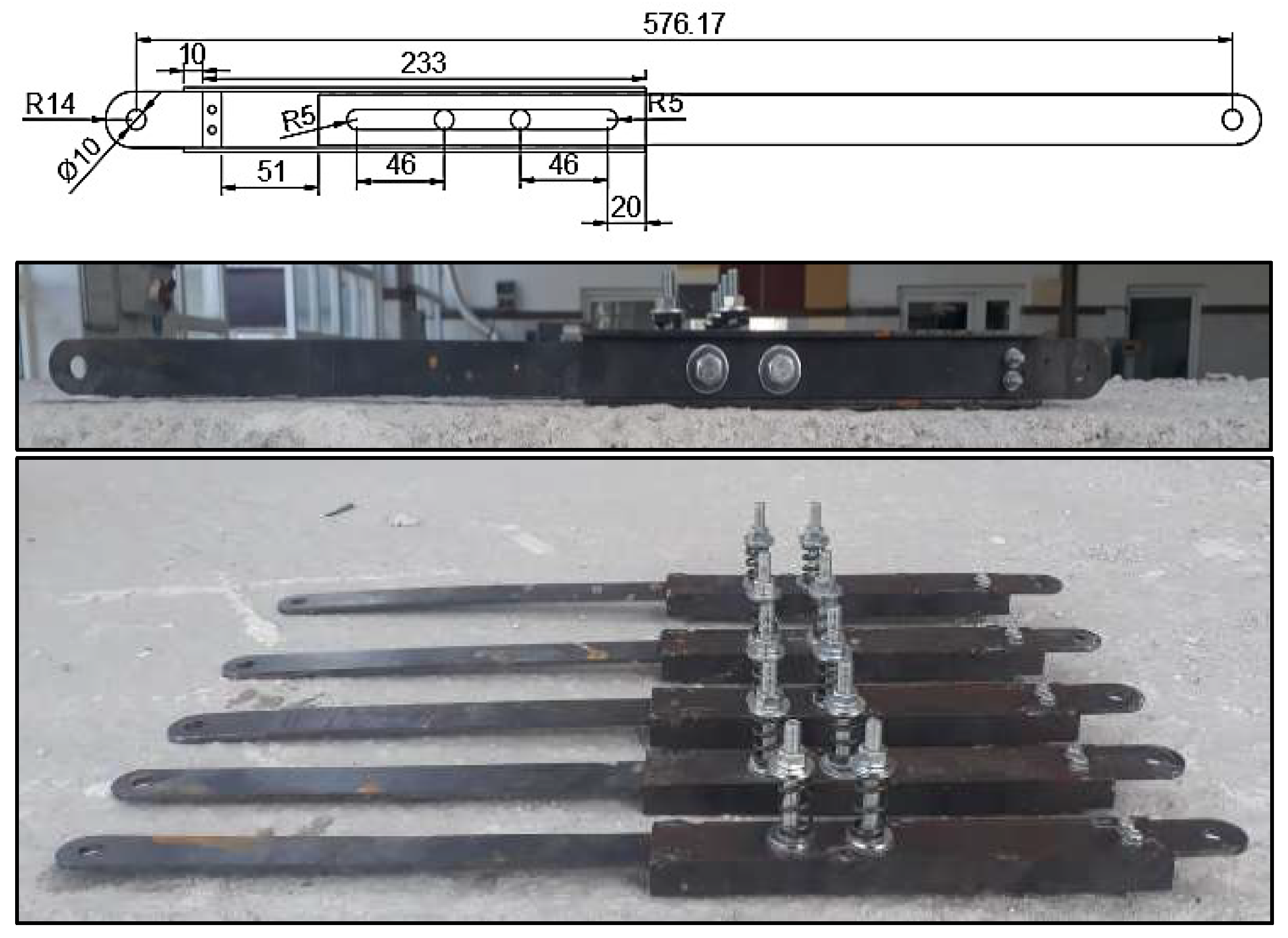
The required pre-tension force in the bolts of friction dampers with helical compression springs was applied. The reason for this is that the minimum pre-tensioning amount that could be given to the bolts with classical pre-tension was greater than the required pre-tensioning force. The main functions of helical springs are to store the force applied on them as energy via compression, to apply force to the desired location, and to dampen the incoming impacts [32].
Helical compression springs perform displacement that is inversely proportional to their stiffness when impacted by an “F” force. In the equation of F = k.u, if a spring with a stiffness of “k” can be displaced by “u” and the spring can be fixed in its last position by preventing it from returning to its original state, the desired F front tensile force can be obtained in the helical compression spring. Thus, it can be seen that the amount of displacement to be applied to the springs is directly proportional to the desired pre-tensioning force in the damper on the relevant floor. The stiffness of the compression spring was calculated using Equation (1) [33]. Springs with the desired rigidity were specially manufactured using a spring drawing machine.
k baskı = d 4 · G 8 · N e · D 3   N / mm
Here, d: diameter of spring wire (mm), D: ring (average) diameter of spring (mm), Di: inner diameter of spring ring (mm), G: shear modulus (G = 80,000 (N/mm2) for steel springs), N: number of spring turns, Ne: number of effective spring turns, Dd: outer diameter of spring ring (mm).
The pre-tensile force value that must be applied to the bolts in order to obtain the optimum sliding force required in the friction dampers was calculated using Equation (2) [34].
R n = μ   ·   D u ·   h f   ·   T b   ·   n s
Here, Rn is the friction-acting design shear force for a bolt, Du is defined as a coefficient showing the ratio of the average pre-tension force applied during bolt assembly to the characteristic minimum pre-tension force, and is taken equal to 1.0. Provided that it shows suitability, Du ≤ 1.13, and different values can be used. ns: number of slip planes with friction effect, Tb: minimum bolt given tensile force, μ: average friction coefficient given or experimentally determined for A-, B-, C-, and D-class surfaces, hf: feed plate coefficient
In order to obtain the required pre-tensioning on the bolts, the springs must be compressed in proportion to the required pre-tensioning on the bolts. To find the amount of compression required in the spring, the pre-tension value required is divided by the spring stiffness. In Table 3, the required pre-tension forces and compression amounts of the helical springs are given.
The dimensions and visuals of the friction dampers using S235 steel and 8.8 M8 bolts are given in Figure 2.

2.2. Experimental Setup

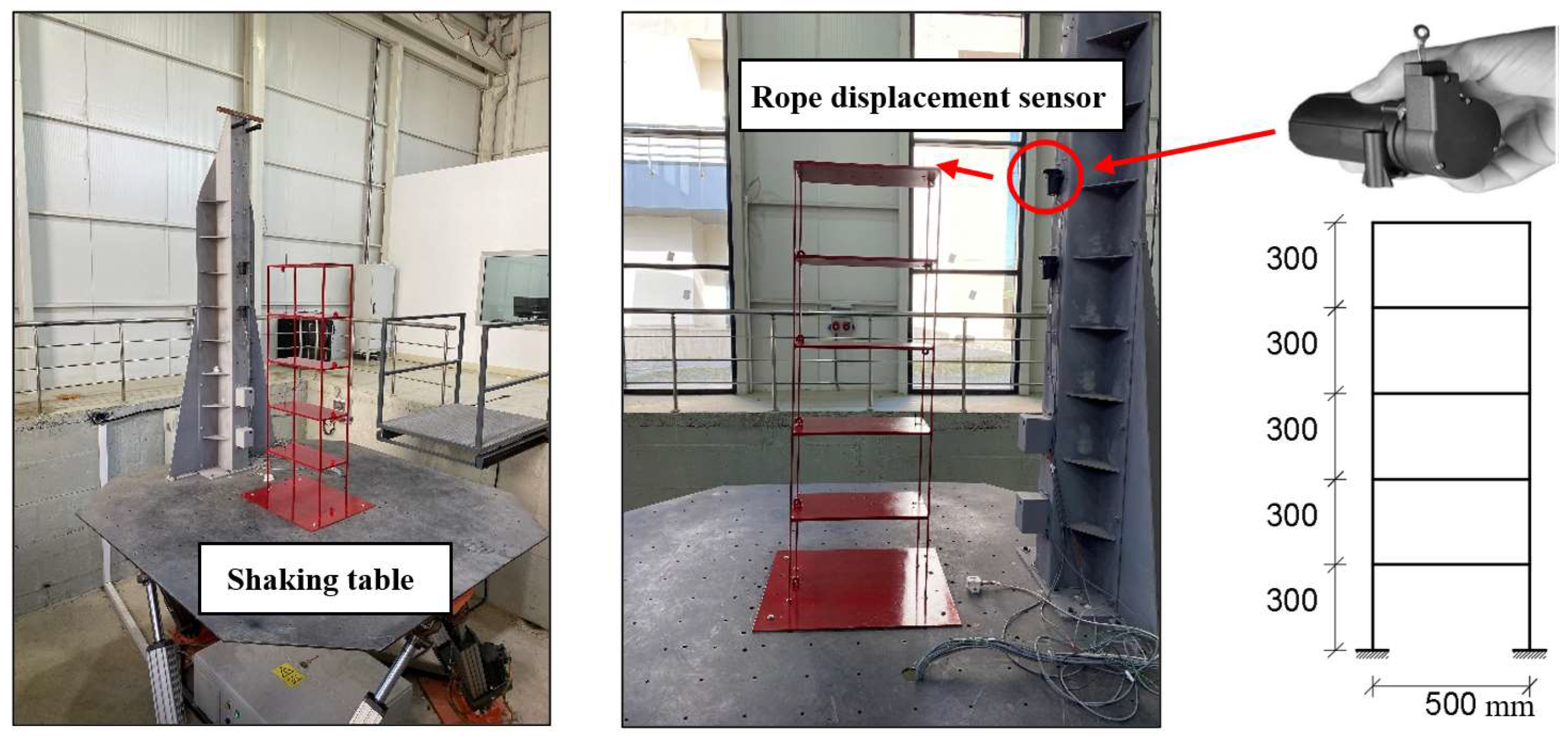
In the first stage of the study, free vibration records from the experimental models were used to determine the building periods. These data were used to validate the numerical model created in Sap2000. A shaking table and a rope displacement sensor were used to record free vibration. The shaking table has six degrees of freedom and a load carrying capacity of 20 kN. The displacements in the floors as a result of free vibration were recorded using a rope position meter that can measure with 77 μm precision. The model building was fixed to the shaking table (Figure 3).
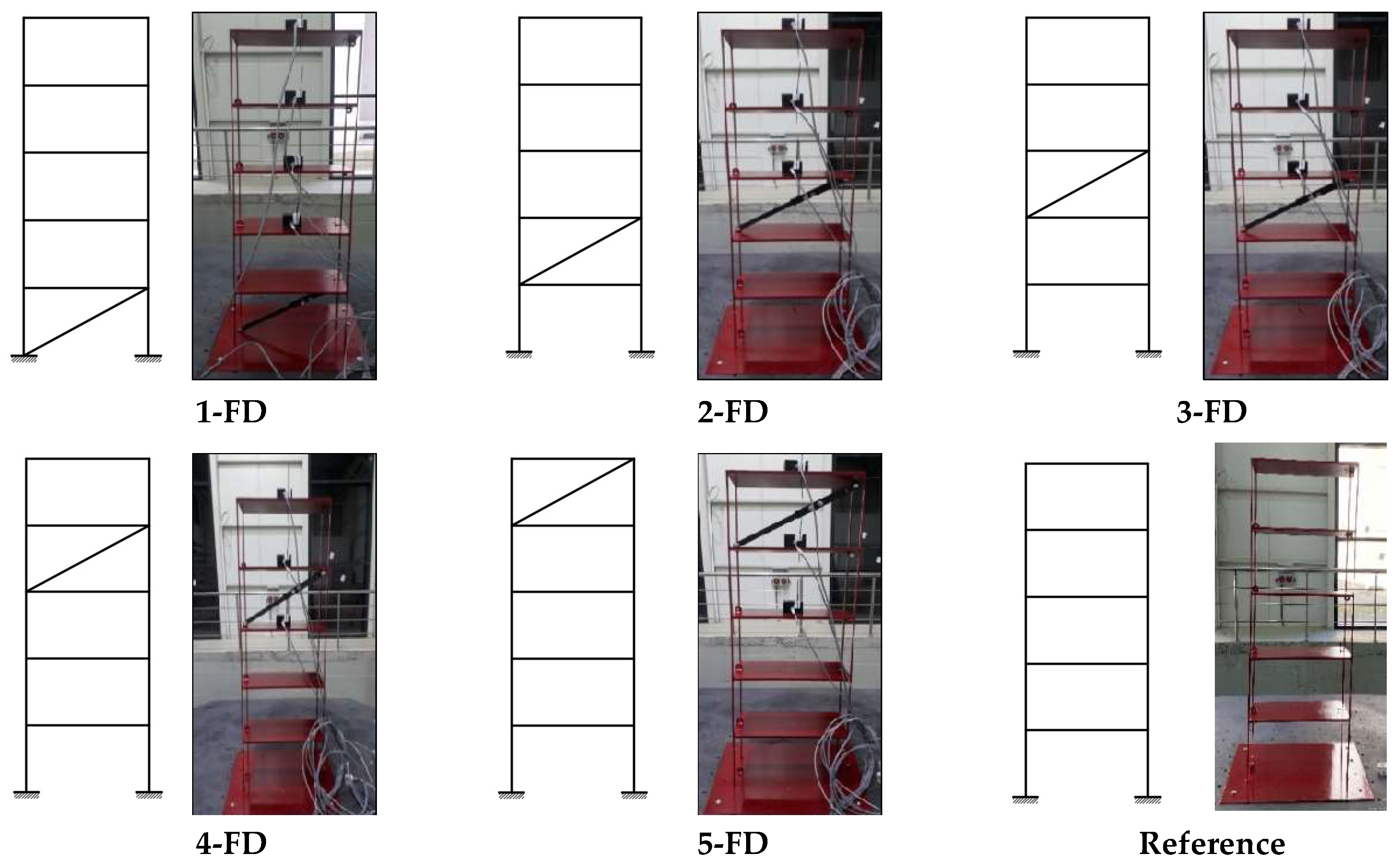
The experimental model without a damper was named “Reference”. Fifteen different layout configurations were created with dampers in order to examine the effect on building behavior when the friction damper was placed on different floors. Five of them were used in the experimental study (Figure 4). In naming the configurations, the floor number of the dampers and the abbreviation “FD” for friction damper were used. For example, the configuration with a friction damper only on the 5th floor was named 5-FD.

2.3. Experimental Model Free Vibration Data

In order to determine the modal behavior of the experimental models, first of all, their free vibration behavior was examined. As a result of free vibration, roof displacement–time graphs were obtained from the models (Figure 5).
By evaluating the free vibration data, the period values of the models were determined. According to the Reference model, the highest period was obtained in the building model with a damper on the fifth floor (5-FD), while the lowest period was obtained in the building model with a damper on the first floor (1-FD) (Table 4).
When the period values are examined, the models with dampers had a reduction of 23% in 1-FD, 14% in 2-FD, 9% in 3-FD, and the same as the Reference in 4-FD, and a 0.3% increase in 5-FD. It was determined that the dampers used on the lower floors provided a large percentage change in the period of the building, so the dampers used on the lower floors had a greater effect on the behavior of the building.

3. Numerical Studies

Period values were obtained from the numerical models of the buildings created in Sap2000 (Figure 6). The numerical model validation was performed by comparing the periods with the experimental model results (Table 5).
The differences between the period values of the experimental and numerical models were 3.3% in the Reference, 3.7% in the 1-FD model, 6.2% in the 2-FD model, 3.2% in the 3-FD model, 3.7% in the 4-FD model, and 1% in the 5-FD model. In terms of model validation, 6.2%, the highest difference between the periods, was accepted as sufficient (Table 5). With the verified building model, the behavior of buildings with dampers under the effect of earthquakes was investigated. A total of fifteen damper building models were created by adding ten more to the damper configurations used in the experiment (Figure 7).

Earthquake Acceleration Records in Numerical Analysis

In the time history analysis, scaled in accordance with the scale of the building as an earthquake effect, Imperial Valley (El Centro Station, 1942) with maximum acceleration of 4.22 m/s2, Kobe (Amagasi Station, 1995) with a maximum acceleration of 4.77 m/s2, and Kocaeli (Ambarlı Station, 1999) with a maximum acceleration of 2.45 m/s2 were used (Figure 8a). In the acceleration response spectra obtained from the earthquake acceleration records for 5% damping, the acceleration value in the numerical building period of 0.27 s shown with red line on the graph. The acceleration value at 0.27 s in the Imperial Valley earthquake was 6.73 m/s2; in the Kobe earthquake, it was 8.1 m/s2; and in the Kocaeli earthquake, it was 2.57 m/s2 (Figure 8b).

4. Results and Discussion

4.1. Hysteresis Responses of Friction Dampers

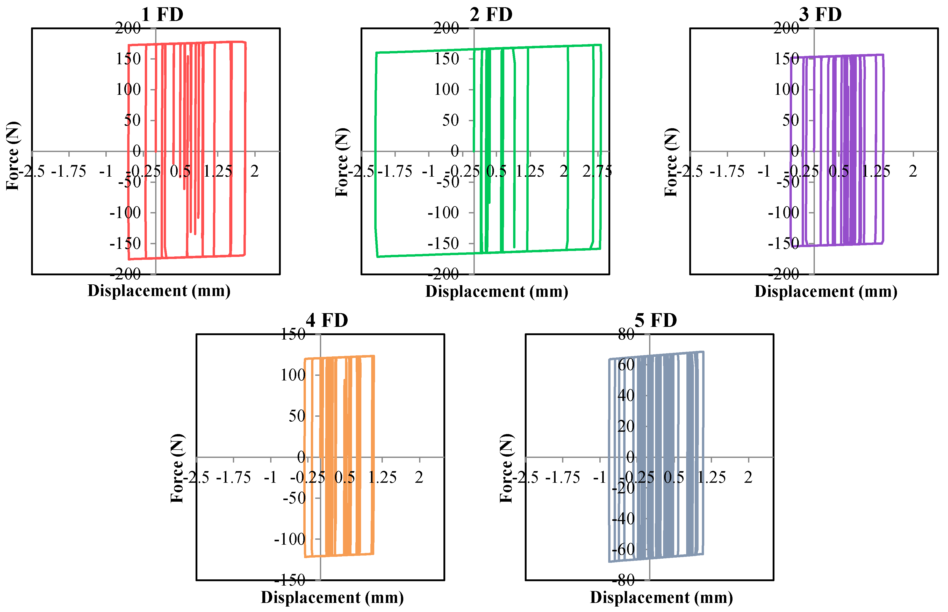
The hysteretic responses of the friction damper configurations placed one-by-one on the floors were examined. The Kobe earthquake, with the highest response acceleration, was used for the shaking table tests of the friction dampers (Figure 9).
The friction forces obtained were 174 N, 166 N, 153 N, 121 N, and 66 N in the 1-FD, 2-FD, 3-FD, 4FD, and 5-FD configurations, respectively. All friction forces were higher than the friction damper design force.

4.2. Comparison of Peak Roof Displacements

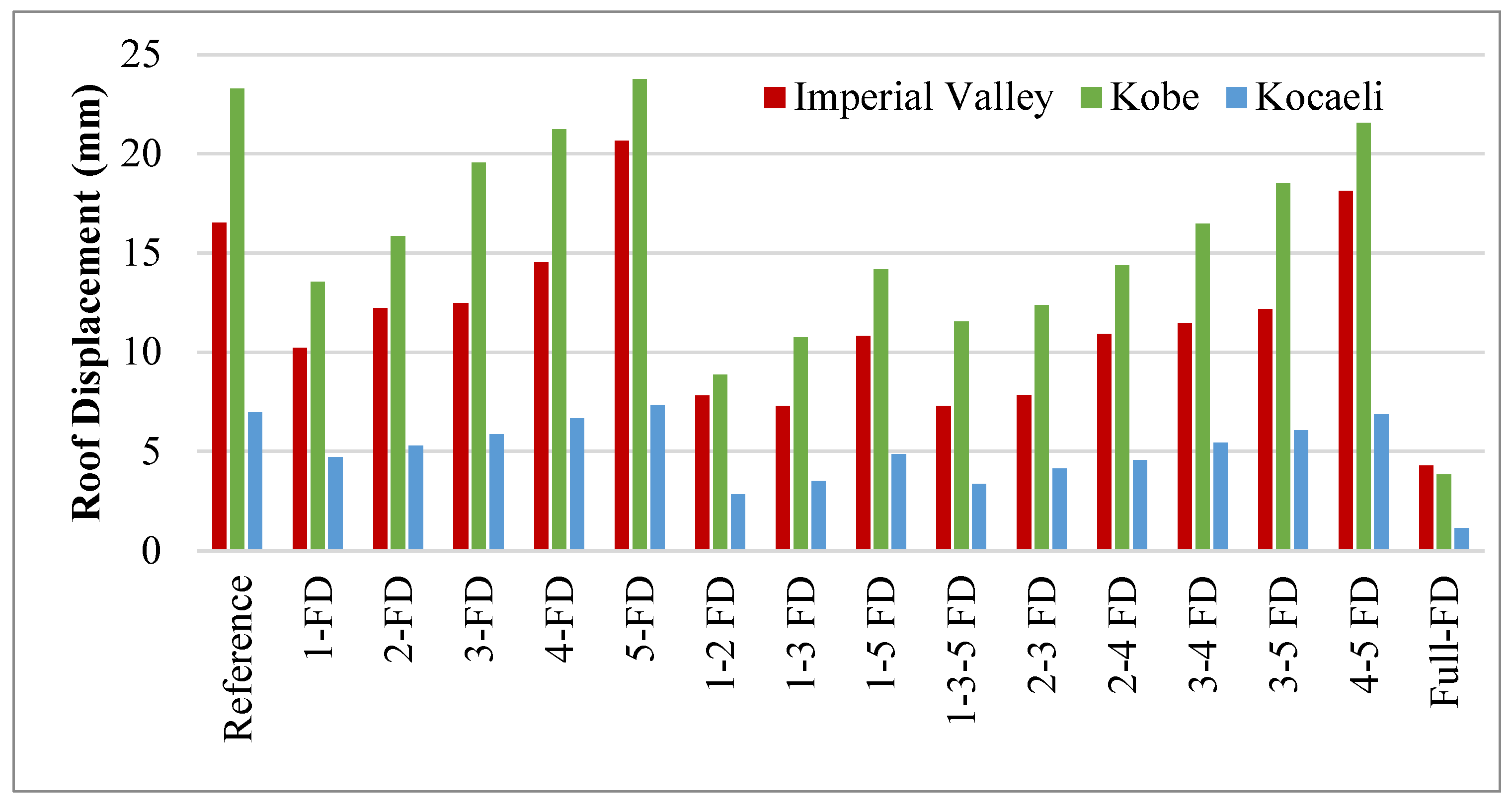
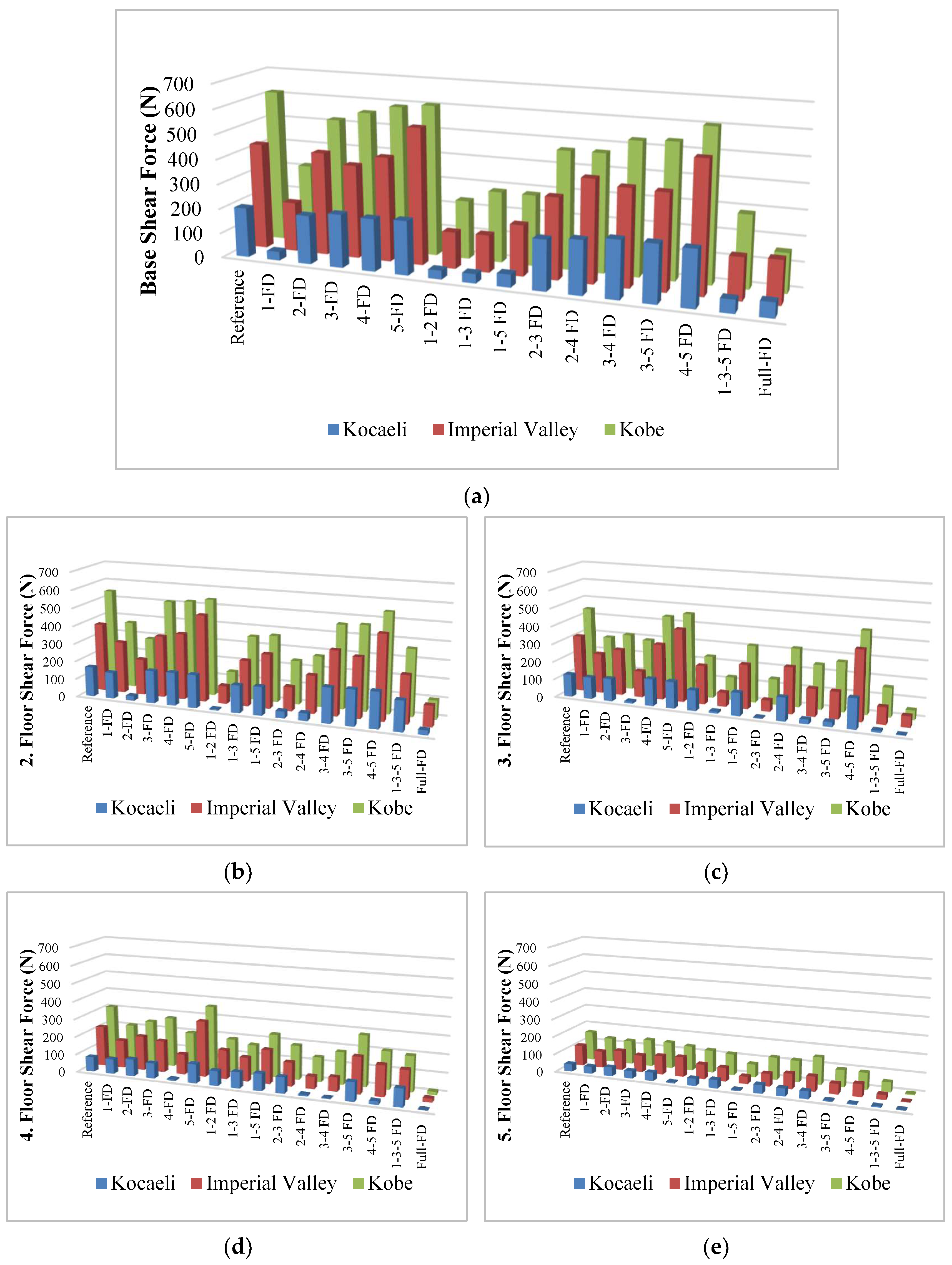
In order to determine the effect of dampers on building behavior, the roof displacement, (Table 6, Figure 10) base shear forces (Table 7), and floor shear forces (Figure 11) of all configurations with the effect of earthquake time histories were compared. All comparisons were made against the Reference building.
The highest displacements occured in Kobe, followed by Imperial Valley, and the lowest displacements occurred in the Kocaeli earthquake. The acceleration record with the highest acceleration response in the building period was for Kobe, followed by Imperial Valley, and then, Kocaeli. The roof displacement results confirm this information (Figure 8b).
Displacement reduction ratios represent the change in displacement relative to the Reference model. The displacement at the top of the Reference building under the influence of the Kobe earthquake was 23.30 mm. The highest reduction in displacement obtained relative to the Reference was 83.56% for the Full-FD configurations, 62.23% and 53.86% for 1-2 FD and 1-3 FD, respectively, and 50.64% for 1-3-5 FD. In addition, a 2% higher peak displacement than the Reference was obtained in the 5-FD configuration. Similar behavior sequences occurred for the other earthquake effects, even if the percentages changed (Table 6 and Figure 10).
When all the earthquake results were examined, in the case where dampers were used on the first two floors of the building (1-2 FD), the reduction rate observed in displacement compared to the Reference building was at least 52%. In the 1-3 FD models, the rate obtained was at least 49%. In the 2-4 FD model, the displacement reduction ratio was at least 33%. In the 1-3-5 FD model, on the other hand, there was at least a 50% reduction in displacement at the apex, and at least a 62% reduction in the apex in the Full-FD model. In the 5-FD model, the peak displacement increased in all earthquake effects. This result shows that improper damper placement may have a negative effect on the earthquake behavior of a building.

4.3. Comparison of Base and Floor Shear Forces

The story shear forces formed on each of the floors due to the effects of the three different earthquakes were obtained. Similar to the displacement values, the highest story shear force values occurred due to the Kobe, Imperial Valley, and Kocaeli earthquakes’ effects, respectively (Table 7, Figure 11).
The first floor’s shear force in the Reference building in the Kobe earthquake was three times that of the Kocaeli earthquake. In the Imperial Valley earthquake, the shear effect was twice as great as that of the Kocaeli earthquake. The acceleration spectra in the building period (0.27 s) confirm this result. When the frictional damping effects were examined, the maximum shear force reduction in the Imperial Valley earthquake was obtained in the 1-2 FD, 1-3 FD, 1-3-5 FD, Full FD, 1-FD, and 1-5 FD configurations. The reduction rates varied between 50 and 65%. The highest reduction was obtained in the Full FD, 1-2 FD, 1-3 FD, 1-5 FD, 1-3-5 FD, and 1-FD configurations in the Kobe earthquake. The percentage decrease varied between 62 and 48%. In the Kocaeli earthquake, rates were 82.4%, 82.3%, 81.4%, 74.6%, 73.4%, and 70% in 1-FD, 1-2 FD, 1-3 FD, 1-5 FD, 1-3-5 FD, and the full FD configurations, respectively. The first floor shear effect was reduced (Table 7, Figure 11a).
The variation in the floor shear forces on each of the floors is presented graphically (Figure 11). Considering the changes in the second-floor shear force, the highest reduction effect was obtained in the Imperial Valley earthquake in the 1-2 FD (74%), Full FD (70%), 2-3 FD (65%), 2-FD (48%) configurations. In the Kobe earthquake with the greatest spectral acceleration, the ranking was as follows: Full FD (81%), 1-2 FD (74%), 2-3 FD (56%), 2-4 FD (49%), and 2 FD (47%). In the Kocaeli earthquake, the following ranking was obtained: 1-2 FD (96%), Full FD (84.4%), 2-FD (84%), 2-3 FD (77%), and 2-4 FD (75%) (Figure 11b).
The third-floor shear force values decreased the most in the Full FD (97%) and 2-3 FD (95%) configurations in the Kocaeli earthquake. There was a 91% reduction in 3-FD, 1-3 FD, 1-3-5 FD, and 80% in 3-4 FD. In the other earthquakes, even if the percentage values changed, the configuration order was the same (Figure 11c). When the fourth-floor shear force values were examined, the highest decrease was obtained in the Full FD (96%) and 3-4 FD (94%) configurations in the Kocaeli earthquake. This was followed by 4-FD and 2-4 FD, with a 90% reduction. The other earthquakes’ results were similar to those for Kocaeli (Figure 11d). The fifth-floor shear force variation ranking was as follows: Full FD (91%), 4-5 FD (90%), 1-5 FD (85%), 3-5 FD (84%), and 5-FD (84%) (Figure 11e).

5. Conclusions and Recommendations

The results obtained as a result of our experimental and numerical studies using fifteen different friction damper configurations on a scaled model building are as follows:
  • In the 1-FD model, depending on the acceleration time histories of the earthquake records, the period value decreased by approximately 17% compared to the Reference building without a damper. This caused an increase of approximately 5% in the period value of the 5-FD building model. This evaluation shows that the dampers used on the lower floors affected the period properties of the building model more than the dampers used on the upper floors.
  • In the case where the damper was placed on the ground floor of the building (1-FD), there was at least a 32% reduction in peak displacement compared to the Reference model without the damper. In the case where we used a damper on the second floor of the building, there was a decrease of at least 24% in the displacement, and at least 6% in the case where dampers were used on the the third and fourth floors. The damper being on the top floor caused an increase of at least 2%. The obtained results show that placing the dampers on the lower floors was more effective for peak displacement.
  • The greatest reduction in roof displacement was obtained in the models where the dampers were placed close to the ground floors (1-2 FD and 1-3 FD). The reduction in displacement was lower in the 1-3-5 FD and Full-FD models than in these models. This result shows the importance of designing the dampers in sufficient quantity and with proper placement.
  • The stiffness of the floor where the dampers were located was increased, thus causing an increase in the earthquake load acting on that floor. Therefore, the roof displacement increased. The increase in displacement in the model in which the friction damper was placed on the top floor of the building (5-FD) confirms this result.
  • The reduction rates in roof displacement varied according to the earthquake record affecting the building. This result shows that the selection of the earthquake record in the design of friction dampers is important.
  • The maximum reduction in shear forces in the building columns was 51% when dampers were used (1-FD) on the first floor of the building, while it was 7% when dampers were used on the fifth floor of the building. Placing the dampers on the lower floors was more effective in reducing the column shear forces.
  • At the frequency corresponding to the building period, the variation in the floor shear force differed according to the spectral acceleration magnitude. Spectral acceleration shows that the damper had a smaller effect on the story shear force in large earthquakes and a greater effect in earthquakes with low spectral acceleration. Even if the ratio decreased, the effect of the damper in reducing the floor shear force was at least 50%. The dampers positively affected the floor where they were located the most, and the lower or upper floors.
When the results are evaluated, it can be said that when a structure with friction dampers is designed, the position and number of dampers in the building are important in terms of seismic behavior. In order to minimize the roof displacement of the building and the internal forces on the structural elements, it has been determined that placing the dampers on the lower floors where the floor shear forces are high increases their efficacy. The decrease in the roof displacement of the building in the models with an increased number of dampers (1-3-5 FD and Full-FD) shows that the cost increases when the damper placement is not carried out properly.

Author Contributions

Methodology, E.A. and E.B.; Software, M.G.; Validation, M.G.; Investigation, E.A., E.B. and M.G.; Writing—original draft, E.A. and E.B.; Visualization, E.A., E.B. and M.G. All authors have read and agreed to the published version of the manuscript.

Funding

This research was funded by Sakarya University of Applied Sciences Scientific Research Projects Coordination, grant number: 016-2020.

Institutional Review Board Statement

Not applicable.

Informed Consent Statement

Not applicable.

Data Availability Statement

Not applicable.

Acknowledgments

This study was financially supported by Sakarya University of Applied Sciences Scientific Research Projects Coordination (project number 016-2020).

Conflicts of Interest

The authors declare no conflict of interest.

References

  1. Bastami, M.; Jazany, R.A. Development of Eccentrically Interconnected Braced Frame (EIC-BF) for seismic regions. Thin-Walled Struct. 2018, 131, 451–463. [Google Scholar] [CrossRef]
  2. Bastami, M.; Jazany, R.A.; Mohamadi, A. Study of the seismic performance of Centrically Fused Braced Frame (CFBF). Thin-Walled Struct. 2019, 145, 106401. [Google Scholar] [CrossRef]
  3. Bastami, M.; Jazany, R.A. Development of centrically fused braced frame (CFBF) for seismic regions. Soil Dyn. Earthq. Eng. 2019, 127, 105856. [Google Scholar] [CrossRef]
  4. Wang, Y.; Zhou, Z.; Zhang, L.; Xie, Q. Quantification of higher mode effects of steel frame and control method using dual self-centering variable friction damper brace. Eng. Struct. 2021, 240, 112368. [Google Scholar] [CrossRef]
  5. Fahnestock, L.A.; Sause, R.; Ricles, J.M. Seismic Response and Performance of Buckling-Restrained Braced Frames. J. Struct. Eng. 2007, 133, 1195–1204. [Google Scholar] [CrossRef]
  6. Hu, J.W.; Noh, M.-H.; Ahn, J.-H. Experimental Investigation on the Behavior of Bracing Damper Systems by Utilizing Metallic Yielding and Recentering Material Devices. Adv. Mater. Sci. Eng. 2018, 2018, 2813058. [Google Scholar] [CrossRef] [Green Version]
  7. Deringöl, A.H.; Güneyisi, E.M. Effect of Friction Dampers on Seismic Performance of Buildings. 2013. Available online: https://tez.yok.gov.tr/UlusalTezMerkezi/tezDetay.jsp?id=ENYl1eqxcSCiCTF5xLFXaw&no=i9g_FMfPLkRpCD7Fj-PEkg (accessed on 2 March 2022).
  8. Constantinou, M.; Soong, T.; Dargush, G. Passive Energy Dissipation Systems for Structural Design and Retrofit, Monograph; Multidisciplinary Center for Earthquake Engineering Research: Buffalo, NY, USA, 1998. [Google Scholar]
  9. Wang, Q.; Shen, H.; Zhang, Z.; Qian, H. Mechanical Behaviors of a Buckling-Plate Self-Centering Friction Damper. Buildings 2023, 13, 440. [Google Scholar] [CrossRef]
  10. Maureira-Carsalade, N.; Balboa-Constanzo, E.; Sanhueza-Cartes, M.; Sanhueza, C.; Núñez, E.; Roco-Videla, A. Proof of Concept and Preliminary Validation of an Analytical Model of an Energy Dissipator for Tension Loads with Self-Centering Capacity. Buildings 2023, 13, 726. [Google Scholar] [CrossRef]
  11. Mazza, F.; Vulcano, A. Displacement-based design procedure of damped braces for the seismic retrofitting of r.c. framed buildings. Bull. Earthq. Eng. 2014, 13, 2121–2143. [Google Scholar] [CrossRef]
  12. Mazza, F.; Vulcano, A. Equivalent viscous damping for displacement-based seismic design of hysteretic damped braces for retrofitting framed buildings. Bull. Earthq. Eng. 2014, 12, 2797–2819. [Google Scholar] [CrossRef]
  13. Sinha, A.K.; Singh, S. Seismic Protection of RC Frames Using Friction Dampers. Int. J. Civ. Eng. Technol. 2017, 8, 289–299. [Google Scholar]
  14. Suk, R.; Altintaș, G. Behavior of multidirectional friction dampers. J. Vib. Control. 2020, 26, 1969–1979. [Google Scholar] [CrossRef]
  15. Saingam, P.; Matsuzaki, R.; Nishikawa, K.; Sitler, B.; Terazawa, Y.; Takeuchi, T. Experimental dynamic characterization of friction brace dampers and application to the seismic retrofit of RC buildings. Eng. Struct. 2021, 242, 112545. [Google Scholar] [CrossRef]
  16. Suk, R. Articulated Friction Type Seismic Damper. Ph.D. Thesis, Manisa Celal Bayar University, Manisa, Turkey, 2019. [Google Scholar]
  17. Afsari, L.; Gökdemir, H.; Günaydın, A. Seismic Analysis of RC Buildings Using X-Braced and Inverted V-Braced Friction Dampers. J. Vib. Eng. Technol. 2023, 1–14. [Google Scholar] [CrossRef]
  18. Yuan, Y.; Wei, W.; Ni, Z. Analytical and experimental studies on an innovative steel damper reinforced polyurethane bearing for seismic isolation applications. Eng. Struct. 2021, 239, 112254. [Google Scholar] [CrossRef]
  19. Gatto, M.P.A.; Montrasio, L.; Berardengo, M.; Vanali, M. Experimental Analysis of the Effects of a Polyurethane Foam on Geotechnical Seismic Isolation. J. Earthq. Eng. 2020, 26, 2948–2969. [Google Scholar] [CrossRef]
  20. Gökçe, T.; Orakdöğen, E.; Yüksel, E. Improvement of the polyurethane spring isolation device for HV post insulators and its evaluation by fragility curves. Earthq. Spectra 2021, 37, 1677–1697. [Google Scholar] [CrossRef]
  21. Zhai, Z.; Guo, W.; Liu, Y.; Zou, S.; Zhou, F. Enhancing the Seismic Resilience of Steel Moment Resisting Frame with a New Precast Self-Centering Rocking Shear Wall System. Buildings 2022, 12, 1957. [Google Scholar] [CrossRef]
  22. Wang, Y.; Zeng, B.; Zhou, Z.; Huang, L.; Yao, J. Shaking table test of a three-story frame with resilient variable friction braces. J. Constr. Steel Res. 2022, 192, 107252. [Google Scholar] [CrossRef]
  23. Monir, H.S.; Zeynali, K. A modified friction damper for diagonal bracing of structures. J. Constr. Steel Res. 2013, 87, 17–30. [Google Scholar] [CrossRef]
  24. Couch, L.; Tehrani, F.M.; Naghshineh, A.; Frazao, R. Shake Table response of a dual system with inline friction damper. Eng. Struct. 2023, 281, 115776. [Google Scholar] [CrossRef]
  25. Zhang, M.; Wang, D. Seismic response analysis of frame with friction damper. Eng. Comput. 2019, 36, 2220–2239. [Google Scholar] [CrossRef]
  26. Shirai, K.; Horii, J.; Fujimori, T. Optimal sliding force characteristics of friction dampers for seismic response control of building structures considering sway-rocking motion. Soil Dyn. Earthq. Eng. 2021, 149, 106892. [Google Scholar] [CrossRef]
  27. Jarrahi, H.; Asadi, A.; Khatibinia, M.; Etedali, S. Optimal design of rotational friction dampers for improving seismic performance of inelastic structures. J. Build. Eng. 2019, 27, 100960. [Google Scholar] [CrossRef]
  28. Chan, R.W.; Tang, W. Serviceability conditions of friction dampers for seismic risk mitigations. Structures 2021, 35, 500–510. [Google Scholar] [CrossRef]
  29. Chou, C.-C.; Tseng, W.-H.; Huang, C.-H.; Tsuang, S.; Chang, L.-M.; Chen, Y.-H. A novel steel lever viscoelastic wall with amplified damper force-friction for wind and seismic resistance. Eng. Struct. 2020, 210, 110362. [Google Scholar] [CrossRef]
  30. Baran, T. Yapıların Dinamik Davranışının Deneysel ve Teorik Olarak İncelenmesi. Ph.D. Thesis, Çukurova University, Adana, Turkey, 2008. [Google Scholar]
  31. Sollogoub, P. Seismic Testing, Advanced Course on Advanced Earthquake Engineering Analysis; CISM: Udine, Italy, 2006. [Google Scholar]
  32. Hocaoglu, H. Fatigue test device design for die springs. Uludag Univ. J. Eng. Fac. 2017, 22, 163–178. [Google Scholar] [CrossRef]
  33. Childs, P.R.N. (Ed.) Chapter 15—Springs. In Mechanical Design Engineering Handbook; Butterworth-Heinemann: Oxford, UK, 2014; pp. 625–675. [Google Scholar] [CrossRef]
  34. Çelik Yapıların Tasarım, Hesap ve Yapım Esaslarına Dair Yönetmelik, Design of Steel Buildings Code, Türkiye. 2016. Available online: https://www.resmigazete.gov.tr/eskiler/2018/02/20180215M1-4-1.pdf (accessed on 6 March 2023).
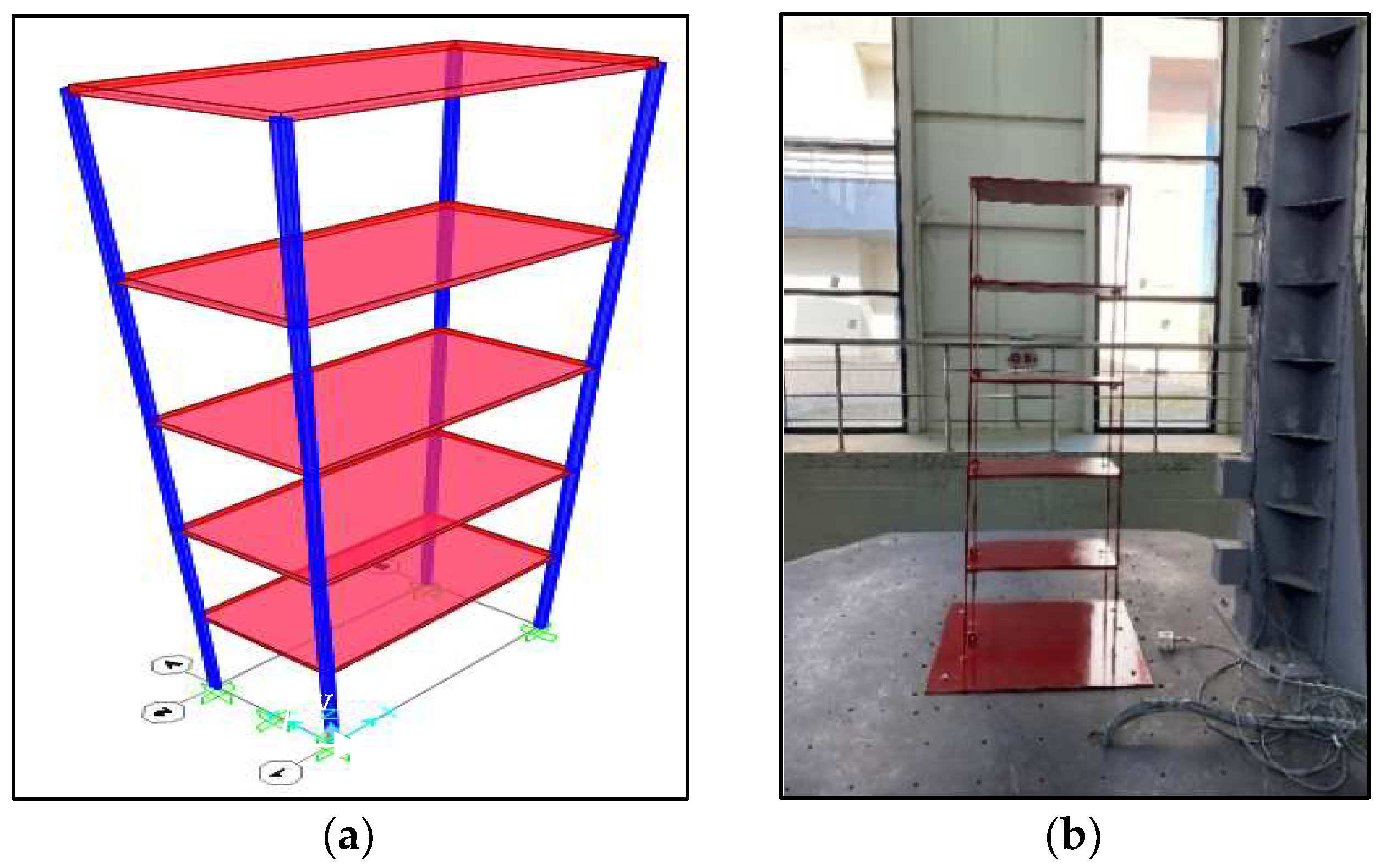
Figure 1. Model building: (a) numerical model; (b) experimental model.
Applsci 13 08311 g001
Figure 2. Friction dampers (unit of measurement is mm).
Applsci 13 08311 g002
Figure 3. Experimental setup and experimental model.
Applsci 13 08311 g003
Figure 4. Positions of friction dampers in the experimental study.
Applsci 13 08311 g004
Figure 5. Free vibration graphs of Reference model and models with friction dampers.
Applsci 13 08311 g005
Figure 6. Mode shapes and periods of numerical models.
Applsci 13 08311 g006
Figure 7. Additional damper configurations.
Applsci 13 08311 g007
Figure 8. Scaled earthquake (a) acceleration records and (b) acceleration response spectras (red line: 0.27 s, model building’s period).
Applsci 13 08311 g008
Figure 9. Hysteretic responses of friction dampers.
Applsci 13 08311 g009
Figure 10. Roof displacements of all configurations.
Applsci 13 08311 g010
Figure 11. Floors’ shear forces. (a) Configurations base shear forces. (b) 2nd floor shear forces. (c) 3rd floor shear forces. (d) 4th floor shear forces. (e) 5th floor shear forces.
Applsci 13 08311 g011
Table 1. Earthquake loading similarity laws created by Sollogoub [31].
QuantityAcceleration Similarity
Displacement, δλ1/2
Speed, vλ1/2
Acceleration, a1
Mass, mλ2
Density, ρ1/λ
Weight, Wλ2
Force, Qλ2
Time, tλ1/2
Frequency, f1/λ1/2
Weight stress, σ1
Seismic stress, σ1
Table 2. Scaling of the structure using the geometric scaling factor.
Geometric Scaling FactorX Direction
(mm)
Y Direction
(mm)
Total Building Height
(mm)
Weight
(kg)
Frequency
(Cycles/Second)
nλ = 1/n
114000200012,00033,593.921.41
20.52000100060004199.241.99
40.2510005003000524.912.82
60.167666.67333.332000155.533.45
80.125500250150065.613.99
Table 3. Calculated pre-tension force (Tb) for dampers and compression amount of helical springs.
DamperRnμ D u n s hfNumber of Bolts T b
(N)
Compression Amount
(mm)
1st floor173.830.21212217.298.309
2nd floor165.670.21212207.097.919
3rd floor153.290.21212191.627.327
4th floor120.590.21212150.735.764
5th floor65.750.2121282.193.143
Table 4. Periods of experimental models.
Reference1-FD2-FD3-FD4-FD5-FD
Period (sec)0.2800.2160.2400.2560.2800.288
Table 5. Periods of experimental and numerical models.
Period (sec)Reference1-FD2-FD3-FD4-FD5-FD
Experimental0.2800.2160.2400.2560.2800.288
Numerical model0.2710.2240.2260.2480.2700.285
Table 6. Peak roof displacements of buildings under the effect of different earthquakes.
Imperial ValleyKobeKocaeli
ConfigurationRoof
Displacement
(mm)
Displacement
Reduction Rate
(%)
Roof
Displacement
(mm)
Displacement
Reduction Rate
(%)
Roof
Displacement
(mm)
Displacement
Reduction Rate
(%)
Reference16.53-23.30-7.00-
1-FD10.21−38.2313.60−41.634.70−32.86
2-FD12.21−26.1315.90−31.765.30−24.29
3-FD12.46−24.6219.60−15.885.90−15.71
4-FD14.53−12.1021.20−9.016.65−5.00
5-FD20.6624.9823.802.157.304.29
1-2 FD7.80−52.818.80−62.232.80−60.00
1-3 FD7.28−55.9610.75−53.863.50−50.00
1-5 FD10.81−34.6014.20−39.064.90−30.00
1-3-5 FD7.29−55.9011.50−50.643.35−52.14
2-3 FD7.85−52.5112.40−46.784.10−41.43
2-4 FD10.93−33.8814.40−38.204.55−35.00
3-4 FD11.48−30.5516.50−29.185.40−22.86
3-5 FD12.18−26.3218.50−20.606.05−13.57
4-5 FD18.149.7421.55−7.516.85−2.14
Full-FD4.28−74.113.83−83.561.10−84.29
Table 7. Base shear forces in different configurations.
Base Shear Force (N)
Reference1
FD
2
FD_
3
D_
4
FD_
5
FD_
1-2
FD
1-3
FD
1-5
FD
2-3
FD
2-4
FD
3-4
FD
3-5
FD
4-5
FD
1-3-5
FD
Full
FD
Kocaeli200.535.30195.8214.6210.7216.635.437.351.0200.9213.5229.1228.6224.253.360.3
Imperial Valley 428.1199.3415.2375.9419.5547.4146.4149.1202.9324.9408.1385.9381.6518.6167.6172.4
Kobe616.5319.0520.7559.6592.5607.4235.8284.9284.9471.7473.6531.5538.8606.0288.7157.4
Disclaimer/Publisher’s Note: The statements, opinions and data contained in all publications are solely those of the individual author(s) and contributor(s) and not of MDPI and/or the editor(s). MDPI and/or the editor(s) disclaim responsibility for any injury to people or property resulting from any ideas, methods, instructions or products referred to in the content.