Review

Recent Progress in Hybrid Additive Manufacturing of Metallic Materials

1
Department of Mechanical Engineering, University of New Brunswick, Fredericton, NB E3B 5A3, Canada
2
Dana Incorporated, Oakville, ON L6K 3E4, Canada
*
Author to whom correspondence should be addressed.
Appl. Sci. 2023, 13(14), 8383; https://doi.org/10.3390/app13148383
Submission received: 15 June 2023 / Revised: 4 July 2023 / Accepted: 17 July 2023 / Published: 20 July 2023
(This article belongs to the Special Issue Novel Research on Laser Additive Manufacturing for Metal and Alloy)

Abstract

:
Additive Manufacturing (AM) is an advanced technology that has been primarily driven by the demand for production efficiency, minimized energy consumption, and reduced carbon footprints. This process involves layer-by-layer material deposition based on a Computer-Aided Design (CAD) model. Compared to traditional manufacturing methods, AM has enabled the development of complex and topologically functional geometries for various service parts in record time. However, there are limitations to mass production, the building rate, the build size, and the surface quality when using metal additive manufacturing. To overcome these limitations, the combination of additive manufacturing with traditional techniques such as milling and casting holds the potential to provide novel manufacturing solutions, enabling mass production, improved geometrical features, enhanced accuracy, and damage repair through net-shape construction. This amalgamation is commonly referred to as hybrid manufacturing or multi-material additive manufacturing. This review paper aimed to explore the processes and complexities in hybrid materials, joining techniques, with a focus on maraging steels. The discussion is based on existing literature and focuses on three distinct joining methods: direct joining, gradient path joining, and intermediate section joining. Additionally, current challenges for the development of the ideal heat treatment for hybrid metals are discussed, and future prospects of hybrid additive manufacturing are also covered.

1. Introduction

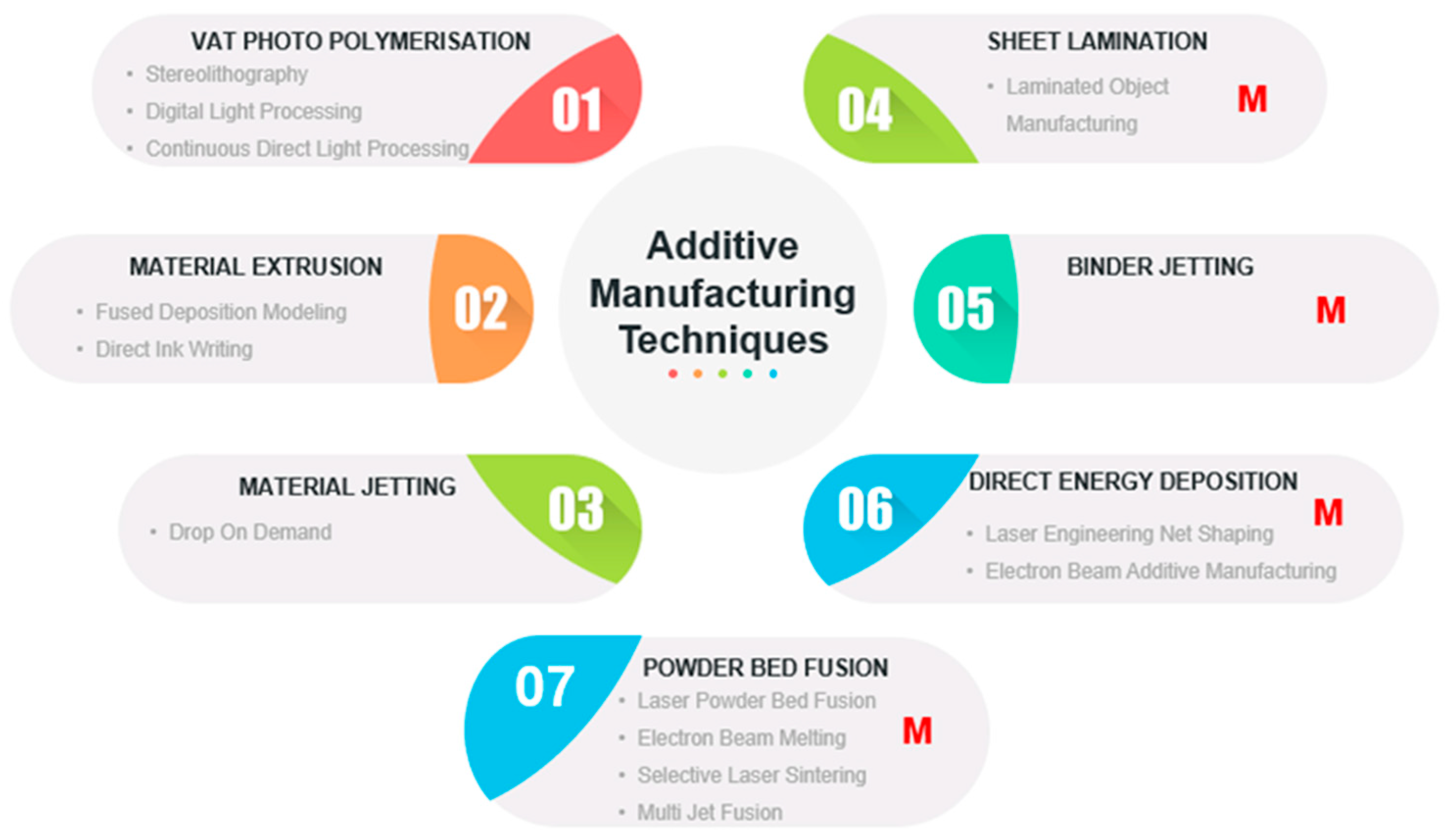
Additive Manufacturing (AM), an advanced technology, has gained prominence due to its focus on enhancing production efficiency by reducing energy consumption and minimizing carbon footprints [1,2]. This process utilizes layer-by-layer material deposition in conjunction with a Computer-Aided Design (CAD) model to create 3D objects. Additive manufacturing has been applied in the fabrication of polymeric, ceramic, composite, and metallic materials [3]. Multiple techniques have been developed for AM [4,5], as shown in Figure 1. Vat photo-polymerization, material extrusion, and material jetting are mainly used for producing polymer-based products with UV-curable polymers, thermoplastic polymers, and jetted polymeric material, which is then UV-curable. Techniques labelled M (in red) in Figure 1 are used for Metal Additive Manufacturing (M-AM) or metal printing. In contrast to traditional manufacturing methods, M-AM has enabled the rapid development of intricate and functionally diverse geometries in metallic components used in various service parts [6,7]. In M-AM processes, various material building approaches are employed. For instance, in the sheet lamination process, metal sheets are accurately cut and then bonded together using metallurgical techniques such as laser welding, diffusion bonding, and resistance welding to create a three-dimensional product. In binder jetting, a binder deposited onto the metal powder consolidates, sinters, or infiltrates another metal into the printed product. Techniques such as Direct Energy Deposition (DED) and Laser Powder Bed Fusion (LPBF) utilize a focused energy source, such as high-energy electrons or laser, to precisely sinter or melt a layer of powders. Among these techniques, LPBF is commonly preferred in the AM community in the production of nickel, titanium, copper-based alloys, and maraging steel components because of its smoother surface finish compared to DED. Moreover, the relative density of parts fabricated by means of LPBF is comparable to that of conventionally produced parts [8].
Metal additive manufacturing processes offer design freedom, which is limited in conventional processes [3]. Complex designs such as topologically optimized cooling channels and consolidated multiple components enable reduced lead and cycle times. Consolidated multiple components refers to the merging of multiple components into one build system and enables the removal of joining surfaces and structures. Consolidating multiple components in a single build has the potential to reduce fabrication and joining costs. In addition, the design freedom offered by AM allows for an optimized material distribution and lightweighting whilst maintaining the minimum mechanical requirements and performance requirements [10]. Metal AM also allows the efficient repair of worn-out parts and saving inventory storage space. Parts can be prepared as per the need or in situ, allowing for an extended component life and efficient servicing of heavy and expensive components such as turbine blades [11].
Despite the novelty of M-AM processes, they have limitations when compared to conventional techniques, specifically in terms of mass production, building rate, build size, and surface quality, as highlighted by Prakash et al. [12] and Popov et al. [13]. Service parts produced by the M-AM process often have rough and stair-cased surface finishes, in addition to internal residual stresses and part distortion. Jayanath et al. [14] reported that non-uniform thermal deformations cause localized stresses in M-AM products, resulting in non-uniform elastic distortions during cooling to room temperature. These mechanical constraints limit a part’s ability to meet structural design fittings, leading to premature failure during fatigue loading due to accumulating and propagating dislocations [15,16]. The presence of a lack of fusion defects was found by Darvish et al. [17] to negatively impact the fatigue life of service components. Sterling et al. [18] and Johnson et al. [19] performed studies on Ti-6Al-4V and IN 718 using the DED—L process, and both affirmed that metallurgical defects act as stress concentrators, which lower fatigue endurance. For the LPBF process, internal pore defects are categorized into Lack Of Fusion (LOF) and gas defects. Lack of fusion defects are often found in the vicinity of spatter particles in between the laser track and powder layers. This is associated with insufficient volumetric energy density and poor powder spreading [20,21]. On the other hand, gas pores include keyhole pores, which are caused by instable melt pools, powder feedstock, and hydrogen pores, which arise from trapped gas and precipitating hydrogen during processing, respectively [21]. Moreover, studies by Zhao et al. [22] showed the importance of the surface quality for the mechanical properties. In situ laser polishing of the IN 718 alloy produced by selective laser melting reduced the surface roughness by about 34%. Laser polishing has the capability of reducing the surface cracks of alloys, fuse surface pores, and melt surface residual powder. The scalability and mass production of these M-AM continue to be a challenge, and these limitations for M-AM pose significant drawbacks in its adoption and application.
Combining traditional manufacturing techniques (milling, casting, etc.) and M-AM could potentially provide new manufacturing solutions relevant to mass production, improved geometrical collaboration, accuracy, and damage repair using net-shape construction [4,13]. From this point forward, the fusion of traditional manufacturing and M-AM will be referred to as hybrid manufacturing or Multimaterial Additive Manufacturing (MMAM) throughout the document. Hybrid manufacturing is relatively in its infancy, and its governing mechanisms are still subjects of great interest. The demand for multi-service superior alloys with multiple properties is rising to suit lightweight functionality, corrosive environments, high-temperature applications, and prolonged exposure to radiation [23]. Additive manufacturing shows a great promise as an alternative to traditional joining techniques for different materials.
Inevitably, complexities arise in these hybrid solutions because of incompatibilities, which may arise due to complex thermal histories, which involve directional heat extraction, varying coefficients of thermal expansion (CTE), repeated melting, and fast localized solidification for the considered metals [7]. In addition, the mechanical behavior of the interface is crucial to developing sound MMAM to avoid premature failure of such components. Components manufactured by metal joining processes are prone to premature failure due to the presence of joints and interfaces between different materials [24]. This behavior can be attributed to the nature of the compositional gradient at the interface.
This review paper explored the types of processes and complexities involved in hybrid manufacturing encompassing joining techniques and combinations with an emphasis on the utilization of AM as a potential joining method for dissimilar metals, in particular, maraging steels. Notably, there has been limited research on joining dissimilar materials, especially of this material type. The discussion will also cover other alloys including stainless steel, Cu-based alloys, and Ni-based steels. Subsequent sections will evaluate different hybrid techniques and their respective performances.

2. Hybrid Techniques Based on the Use of Other Manufacturing Techniques with AM

The term hybrid additive manufacturing is not limited to the use of dissimilar metals, but also encompasses the use of other manufacturing technologies in conjunction with AM to achieve better performance and functionality. Despite positive outcomes of integrating conventional manufacturing techniques with AM in superalloys and steels, hybrid techniques still have limited application in the industry. This is due to the challenges of adopting hybrid AM parameters for each specific material in the hybrid system to match the substrate or for specific geometries [13]. Earlier work by Manogharan et al. [25] explored the possibility of merging additive and subtractive techniques based on individual processes’ limitations and capabilities. This section focuses on hybrid manufacturing techniques, i.e., the use of AM in conjunction with other manufacturing technologies, in situ or post-AM. Note as well that processes such as Selected Laser Melting (SLM) and Selective Laser Sintering (SLS) according to ASTM F42 [26] refer to Powder Bed Fusion (PBF) processes. The names of the processes are given based on the way they were presented in the original manuscripts. Moreover, the discussion in the sections below is focused on the actual technique, since an in-depth analysis (such as texture evaluation) of each method is currently not available.

2.1. Electron Beam Melting + Computer Numerically Controlled Rapid Prototyping

Additive System Integrated Subtractive (AIMS) systems are the combination of Electron Beam Melting (EBM) and Computer Numerically Controlled Rapid Prototyping (CNC-RP) (Figure 2). The AIMS method is used for metallic components, such as the Ti-6Al-4V alloy, in which the tolerances and surface finishes are improved by digital machining post-EBM-AM. The comparative studies between the CNC-RP technique and the AIMS method revealed that the AIMS method is faster, with an estimated buy-to-fly ratio of less than 3. On the other hand, the CNC-RP process has a buy-to-fly ratio greater than 13. The buy-to-fly ratio is the measure of the efficiency of raw material use. It gives the weight ratio of the raw material to the final product [27].
The AIMS process has minimized tool wear and has better material utilization than the CNC–RP technique. However, the authors noted that the subtractive techniques require custom-made tools and fixtures, which can be a limitation for expanding this process [25]. The work conducted identified fixturing limitations when combining the two processes, necessitating the need for customized and more fixture designs tailored to different M-AM techniques.

2.2. Laser Metal Deposition + Computer Numerical Control

Merklein et al. [29] reviewed the Laser Metal Deposition (LMD) AM technique in conjunction with a subtractive process in a single-step procedure. The authors proposed a combination of LMD and CNC milling centers for the aerospace industry by using functional lightweight metals followed by a smooth surface finishing (Figure 3). This technique provides a solution to maximize the production volume whilst eliminating changeover cycles. The LMD process produces moderate thermal gradients and defect-free components. The possibility of the laser alloying of tool alloys was explored to reduce the abrasive and adhesive tool wear. According to reports, the chipping volume was significantly reduced, albeit that this was not quantified. Similar to laser case hardening, the application of laser energy for heating hypothetically proves advantageous in surface hardening of components [29]. Laser metal deposition can facilitate the production of several materials in a single process, and the addition of ceramic inclusions on the surface of the metals was proposed to improve surface wear. In another study, the integration of a direct energy deposition technique with CNC machining was achieved in a process termed the “ArcHLM process”, proposed to be suited for LMD processes [30]. The uniqueness of this technique is that machining is performed after every successive layer of weld-deposited material. As a result of the process, oxide coatings are formed, leading to a rough surface finish. The surface irregularities were estimated to be less than 2 mm. Hence, to avoid a loss of accuracy along the build direction, each layer was face-milled to the required thickness. This study showed that fast deposition rates are achievable; however, there are issues such as the need for controlled heat gradients and atmosphere to minimize oxidation and phase stability. In the case of maraging steels, the cooling to martensite start is crucial to minimize the amount of retained and reverted austenite, which can increase the ductility at the expense of strength. Instead, the use of the SLM process in conjunction with CNC machining has been proposed to be a better alternative [20]. Small melt pools are produced, which allow for faster cooling and better surface quality. The process demonstrated significantly higher hardness values of about 56HRC for the hybrid additive technique in comparison to 40HRC for the material produced solely through printing without heat treatment. This study showed the importance of the surface finish for the mechanical properties. The major setback of this technique is that the time interval between additive manufacturing and machining is not optimized, resulting in long lag times.

2.3. Selective Laser Sintering + Die Substrate

In another work by Oter et al. [31], a Selective Laser Sintering (SLS) technique was used to design a die matrix on an extruded hot steel die, and the resulting work produced a die that did not require post-processing. This work was motivated by the need to address the mismatch between simulation and production results due to human intervention in post-processing correction in conventionally produced extrusion dies, which results in the poor quality of the extruded profile. However, there is proof of decarburization on one of the sections, which created a hardness variation from 381 to 451 HV [31]. The loss of carbon is detrimental to the performance of steel since carbon plays a crucial role in solid solution strengthening, which contributes to its overall strength and performance. Carbon migration is reported to cause sensitization in alloy systems that rely on high chromium contents for corrosion resistance [32].
Preferential deposition of chromium carbides along the grain boundaries increases the chances of localized stress corrosion, especially in austenitic and low-alloy-ferritic steels [33]. The distribution of other alloying elements and how they affect die strength were not explored in this work, potentially giving room for more work in understanding the behavior of the alloying elements.
A study by Aziz et al. [34] explored the possibility of building C300 maraging steel (using MS1 powder) on top of an inexpensive conventional H-13 die structure using Selective Laser Melting (SLM). A sharp contrast was observed between the two alloys and the interface and was reported to be weak due to the microstructure and chemical composition variation at the interface. A low strain-to-fracture average of 0.27 was recorded and localized at the dissimilar joint, and porosity was observed at the interface. Earlier work by Wang et al. [35] deposited 1Cr12Ni2WMoVNb martensitic steel on a wrought bar of a similar material using Laser Melting Deposition (LMD) to produce a sound metallurgical bond, and failure occurred in the wrought substrate zone [35]. In addition, Zhu et al. [36] had similar findings from a TC11 sample produced using LMD. The interface had sound metallurgical bonding, as evidenced by failure in the substrate material during tensile testing. These results showed that careful microstructure development is critical for good metallurgical bonding.

2.4. Wire and Arc Additive Manufacturing Filling + Worn-Out Part

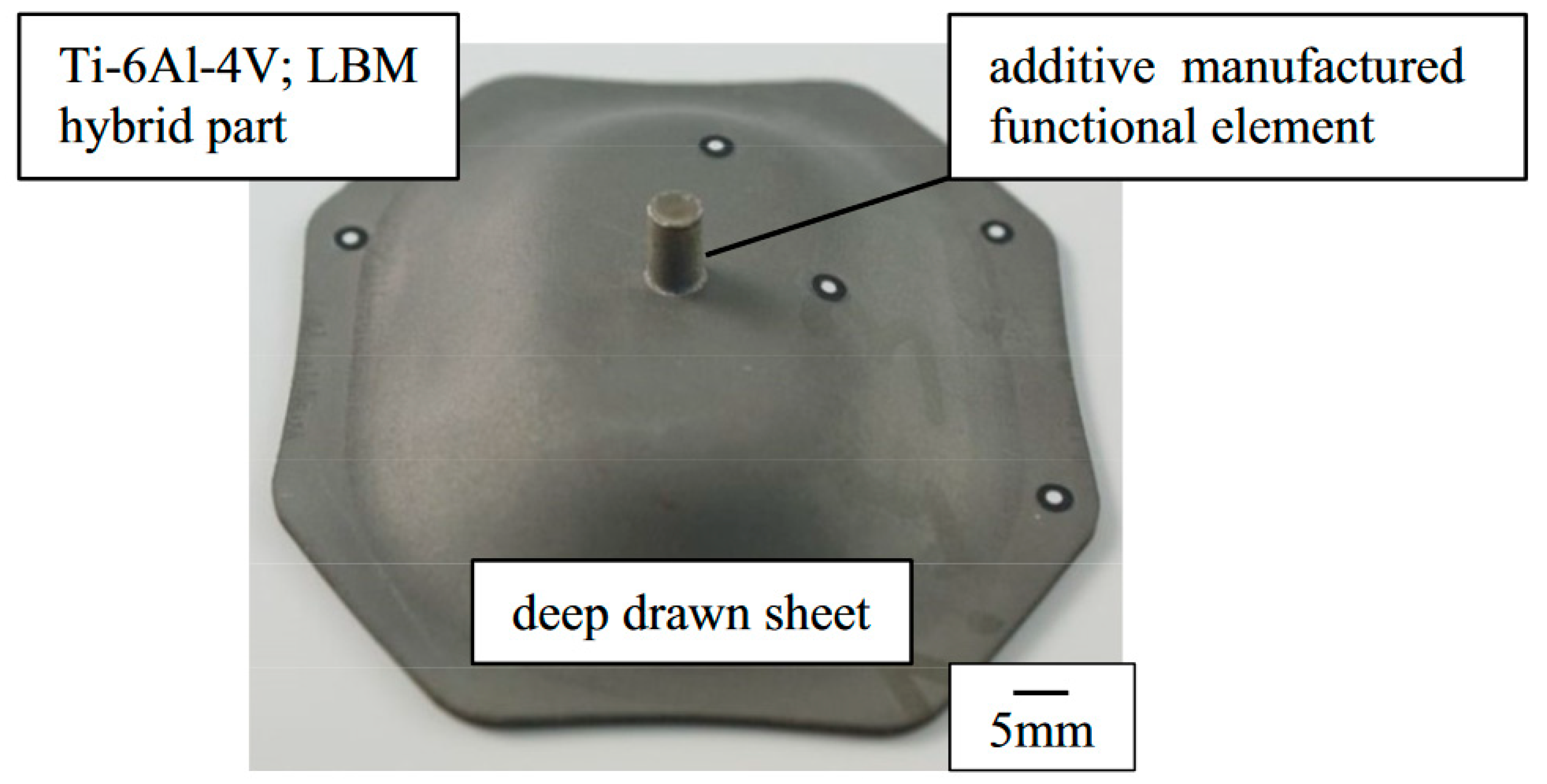
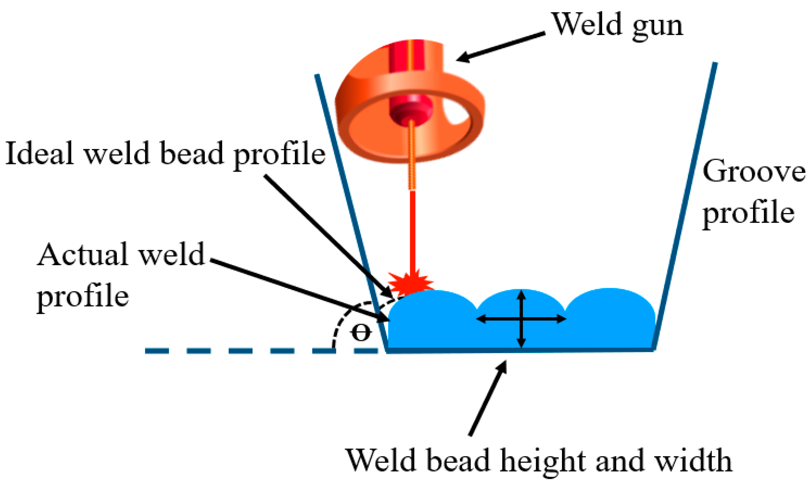
Wire Arc Additive Manufacturing (WAAM) was proposed as an innovative and cost-effective AM solution to repair worn-out parts [37]. This study revealed that the inclination angle between the groove on the worn-out surface and the deposited layer of H0.8Mn2Si was a critical parameter for efficient fusion. Each layer deposited in the cavity must satisfy a specific height to avoid incomplete fusion at the inclined interface, as shown in Figure 4. An optimized height-to-width ratio of a single weld bead corresponded to tanꝊ = 1.377, where Ꝋ was the inclination angle used in this study. This inclination angle enabled free working space for the weld gun, and there was no evidence of weld porosity or crack formation. Despite the evidence of deformation on the repaired section, a buy-to-fly ratio of 0.921 and sufficient fabrication and material were achieved. The deformation was due to the shrinkage of the weld beads and the adjacent substrate metal during cooling [37]. These deformities could be hindrances for repair works that require strict geometrical fittings. As a result, this may ultimately lead to the high post-processing cost of the repaired parts.
Earlier work on IN 718 by Praniewicz et al. [38] investigated the possibility of model analysis on worn-out surfaces and optimized the AM-built weld. The basis of this work was to address the various distortions and worn-out geometries. Transformed CAD geometries were matched to the geometry of deformed samples using an iterative algorithm with a Coordinate Measurement Machine (CMM) for improved precision during adaptive repairs. This approach resulted in a maximum surface deviation of 0.1%. As a result, it was concluded that a material efficiency above 74% and efficient processing times were achievable [38].

2.5. Laser Powder Bed Fusion + Fused Filament Polymer

A process termed “AddJoining” by Chueh et al. [39] uses Fused-Filament-Fabricated (FFF) polymer and a Laser-Based Powder Fusion (LBPF) process for dental applications [40]. Consequently, laser heating and remelting were performed on the interface to ensure the sound interface bonding strength for the different materials. From the observations made, the fracture stress in the polymer section was 22 MPa, and the interface remained intact, indicating a sound polymer infiltration into the metal section and concluding that dissimilar material joining is possible with a thorough understanding of the structure–property relationships.

2.6. SLM + WAAM

Shi et al. [41] explored the feasibility of fusing the SLM and WAAM processes using the Ti-6Al-4V alloy. The SLM process has the advantages of generating fine surfaces and high-density components with good mechanical properties and geometrical flexibility. However, the process has high production costs associated with low building rates and small-scale production [42,43]. On the other hand, WAAM has a high deposition rate and production volume, but it has limited geometrical accuracy and poor surface quality. The synergy of these two processes was implemented to take advantage of each process’s capability, simultaneously limiting their constraints. The SLM-produced component was set as the substrate and was partitioned into two sections, namely the complicated and simple sections. The complicated section’s fabrication was SLM processed, and the rest of the simple section was completed using WAAM. To prevent potential defect formation and maintain a high bonding strength at the interface, the SLM process was employed as the substrate-processing technique. This choice aimed to mitigate the risks associated with defect formation and ensure robust bonding at the interface. From Figure 5, the joining of the AM processes has three zones, the SLM zone, interface zone, and WAAM zones, with an interface of about 3 mm. Each zone appears to have a distinct microstructure. The SLM zone primarily produced short β columnar grains consisting mainly of a martensitic structure. Subsequently, a complex interface with coarse grains caused by repeated heating, facilitating grain growth. The martensite formation is most likely due to high cooling rates from above the β-transit temperature of Ti-alloys. Furthermore, the progression into the WAAM zone revealed an α lamella with evident epitaxial growth. It was found that the WAAM build sections had inferior mechanical properties (yield strength: 1020 MPa, tensile strength: 1098 MPa, and elongation: 10.2%) compared to the SLM section (yield strength: 814 MPa, tensile strength: 927 MPa, and elongation: 10.5%). To confirm the effects of these varied mechanical properties, further testing was conducted on the hybrid parts parallel to the building direction, and failure was observed in the WAAM section with a yield strength of 890 MPa and a tensile strength of 905 MPa. Sections perpendicular to the build direction were evaluated to expand the applicability of this approach; however, it had low mechanical properties (yield strength: 850 MPa, tensile strength: 995 MPa). It was evident that the strength of the hybrid was higher compared to the WAAM component, despite being lower than the SLM component. Thus, the advantages of the combined processes can be realized. In this work, a sound metallurgical bond was achieved with no identifiable defects; however, no heat treatment of the produced hybrid material was performed, which could have optimized the mechanical properties of the alloy [41].

2.7. Laser Metal Deposition + Turning + Milling

Yamazaki [44] developed a hybrid multi-tasking platform (Mazak Hybrid Multi-tasking), which incorporated turning and milling functionalities with an LMD process. The motivation of this study was to reduce the manufacturing and process times for part development. In their work, IN 718 was deposited onto a stainless steel alloy (316S31) using the Mazak Hybrid Multi-tasking machine. The application for this hybrid part was for the offshore oil industry. A material failure occurred on the 316S31 substrate, which had inferior mechanical properties to IN 718. According to the report, a high density was achieved (quantity not specified), and no defects were observed at the interface [44]. However, this is unlikely to occur in such processes, knowing that defects are inevitable [16]. Li et al. [45] modified a similar work by developing a strategy that utilizes a robotic arm with six degrees of freedom and with multi-changeable heads integrated into the system. The goal was to create a multi-axis AM. The optimized 6-DOF hybrid additive–subtractive manufacturing process had an estimated production time savings of above 50%. The proposed system was material-efficient and provided better surface finishes [45].
For convenience, a summary of the selected hybrid solutions discussed in this section is presented in Table 1.

3. Hybrid Additive Manufacturing as a Joining Technique and Its Challenges

To achieve a reliable component fabricated by joining processes, a thorough understanding of the interface behavior of the joined materials is necessary. Traditional joining techniques, such as welding or fastening, have design limitations at the joints. It is well known that there can be localized stresses, corrosion, and inferior mechanical properties in the joints, compared to the parent metals. During welding, materials are heated to a suitable temperature to combine them. A melt pool is created, which solidifies at the rear of the weld pool to create a fusion zone; then, a Heat-Affected Zone (HAZ) is generated adjacent to the base metal. Both AM and welding require localized heat sources to create melt pools. In addition, both have similar behaviors in reacting to the temperature—steep thermal gradients formed at temperatures above the liquidus temperature of the alloy. The cooling behavior of each material depends on the individual chemical composition and thermal expansion coefficient [16]. Regardless of the techniques used, the joining of dissimilar alloys inherits challenges because the areas in the vicinity of the interface tend to produce inhomogeneous structures [48,49]. On the other hand, similar melting joining techniques also develop heterogenous structures at their interfaces. Constricted Arc Welding (GTCAW) was used to join a maraging 250 steel [50], and the resulting microstructure varied across the similar alloy joint. The weld zone region for the maraging steel joint had fine-grained martensite adjacent to a structured dendritic interface. Further away from the weld zone, the HAZ exhibited a mixture of coarse-grained austenitic–martensitic structures. Similarly, a PH 13-8Mo stainless steel joint had a coarse weld [50], resulting in an interface similar to the parent material because of a filler material of similar composition. Such inhomogeneous structures result in various material properties, which are usually undesirable for uniformly loaded structural components [23].
Thermal conductivity differences have been observed in welding to contribute to the lack of fusion in joints, as in AM. Dissipating heat moves faster in the high-conducting material than the low-conducting material, resulting in poor fusion.
To help future studies on hybrid/MMAM and expand the usefulness of alloy compatibility, interface reaction products and thermal property mismatch need to be well understood [23]. The following sub-sections discuss the effects of these parameters based on previous studies.

3.1. Alloy Compatibility

Minor alterations to an alloy’s prescribed composition or thermal history significantly alter its performance and properties, such as resilience, toughness, and resistance to corrosion. Homogeneity in the microstructure is crucial for joint strength for dissimilar metals, as shown in a study by Aziz et al. [34]. Due to chemical and microstructural inhomogeneity, a hybrid built from MS1 and a wrought H-13 maraging steel substrate fractured at the interface. Porosity also contributed to the failure, as reported in the study. A solute variation of alloying elements was observed at the interface transition. The chemical composition changed abruptly from Ni, Mo, and Co-based MS1 to H-13, which is Cr-based. (Figure 6). Chromium diffused through the interface into the MS1 section [34].
In support of this, Conde et al. [51] noted that elemental diffusion caused alloying elements’ depletion and micro-segregation in interdendritic regions. This is consistent with the observations of Shakerin et al. [46], who studied a similar MS1–H13 hybrid material system with some heat treatment modifications. Despite achieving a homogeneous microstructure, adequate precipitation did not reach the interface due to insufficient aging of the required precipitates [46]. Subsequently, sharp compositional interfaces acted as potential gradients, which facilitated the movement of the alloying elements and impurities; these produced various mechanical and physio-thermal properties, which exacerbated the failure.
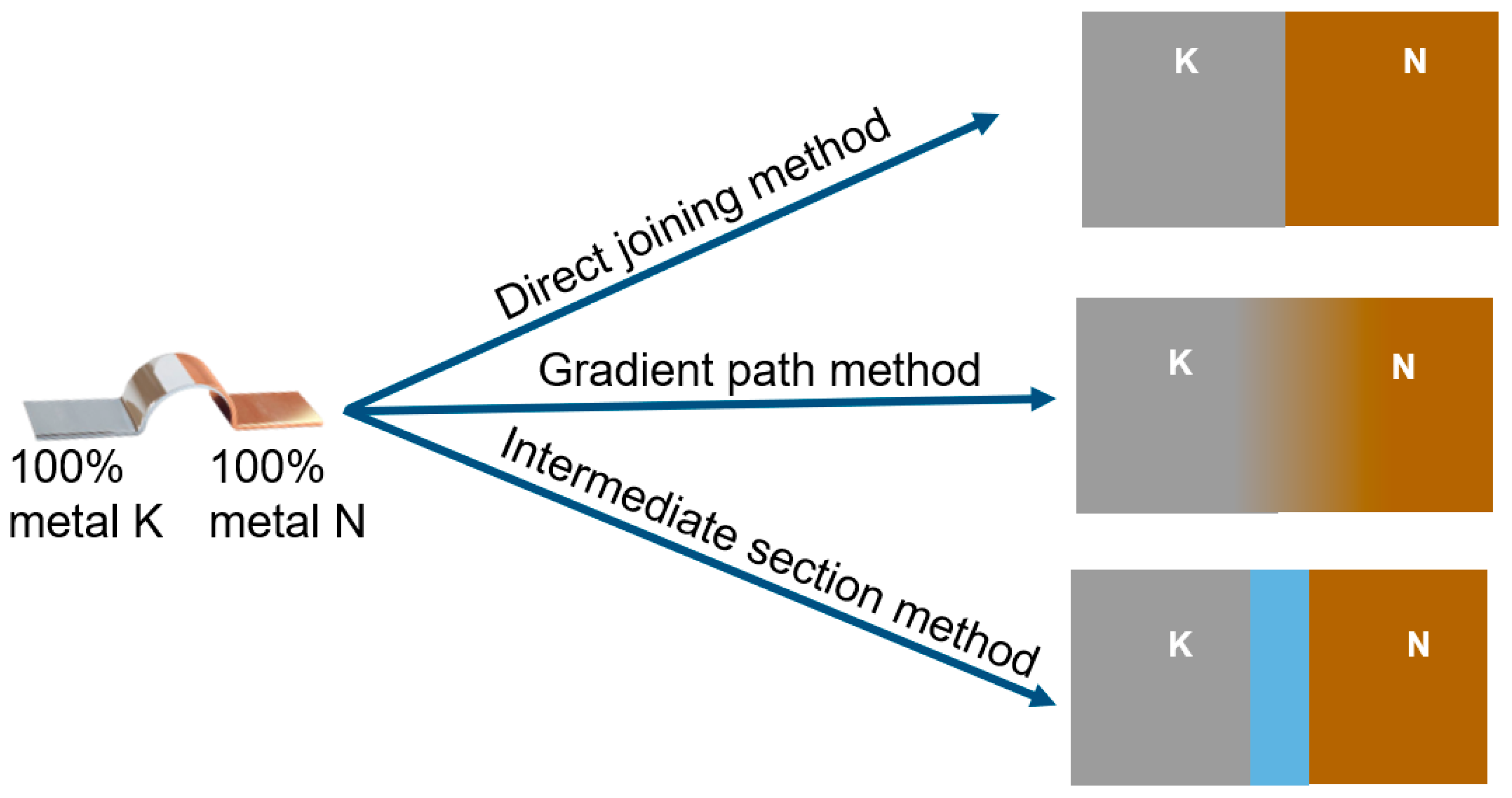
The joining of dissimilar metals can be achieved in three ways, namely direct joining, the gradient path, and the intermediate section, as shown in Figure 7 [52]. The application of each technique is given in the following section with a focus on LPBF. A summary of these joining techniques and their outcomes is given in Table 2.

3.1.1. Direct Joining

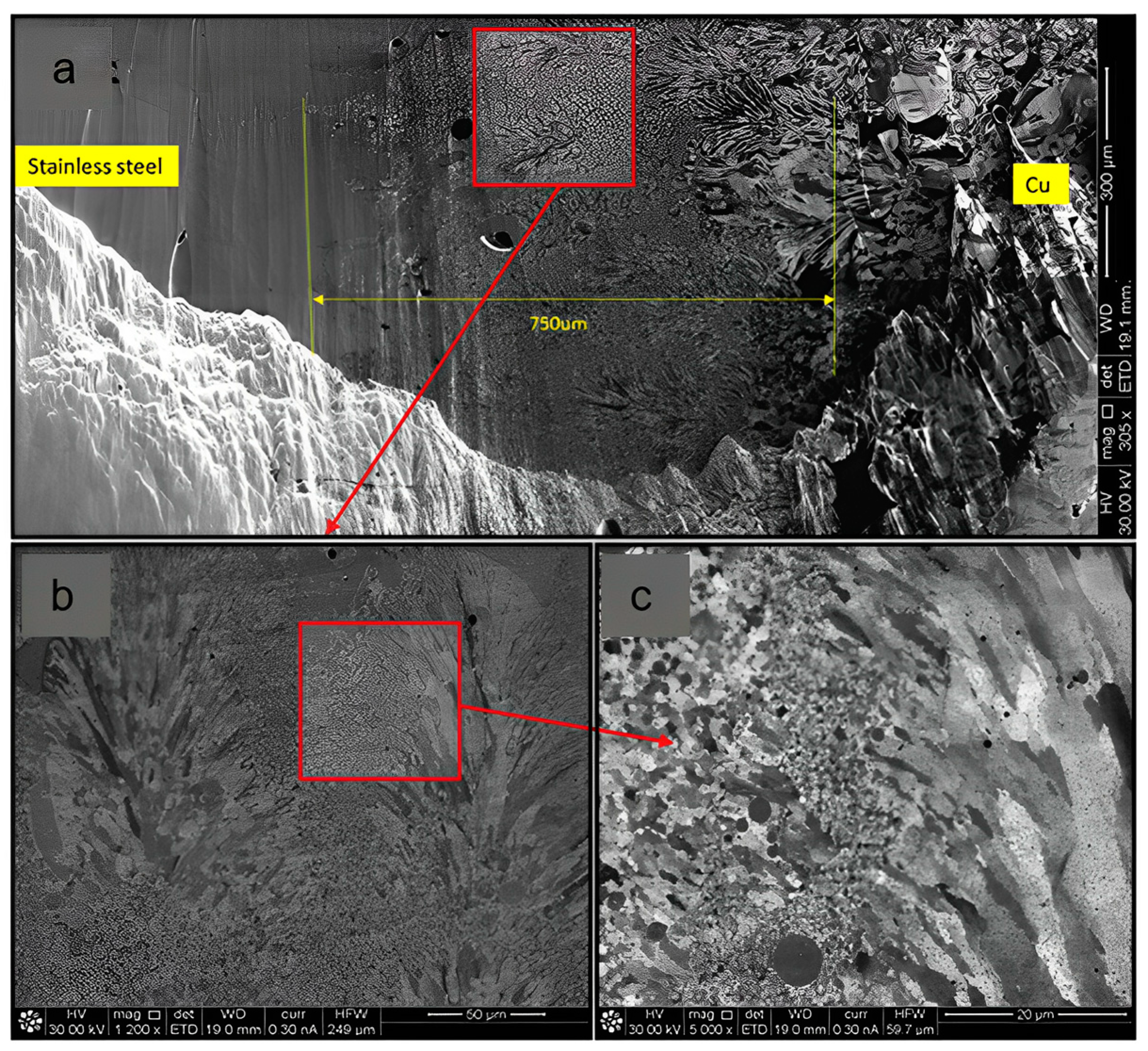
Liu et al. [53] applied the direct joining technique on a 316/C18400 alloy using LPBF. Cracks were observed on the stainless steel section close to the interface because the highly conducting Cu diffused into the austenite grain boundaries, resulting in thermal stress inside the matrix. Fused Ion Beam imaging (FIB) revealed an intermix region, approximately 750 µm in length, with a mixture of fine-grained structures (Figure 8). Inadequate melting caused substantial porosity in the Cu alloy (Figure 8c). This was most likely due to Cu’s high reflectivity and heat conductivity at a 300 W laser power. The copper alloy was melted directly on top of the stainless steel, and a large quantity of copper was presumably present in the melt pool, causing micro-cracks to occur during cooling [53].
LPBF’s slow layer-by-layer building strategy produced an excellent metallurgical bond between 316L and Cu10Sn. In contrast to prior reports, a crack-free interface was obtained [24]. Appropriate melt pool agitation (Marangoni convection) and an equal distribution of alloying components in the heterogeneous alloy phases were acclaimed by Chen et al. [43] for the strong metallurgical bonding. Furthermore, grain refinement and recrystallization improved the bonding performance at the interface with the following operating parameters: a laser power of 400 W and a scanning speed of 500 mm/s [43]. In another work by Hengsbatch et al. [54], a 316L/H13 MMAM produced a sound metallurgical bond at the interface with a build platform temperature of 200 °C. The build temperature was chosen to minimize thermal stresses at the bonding interface. In addition, the good bonding was attributed to the efficient agitation and distribution of elements inside the melt pool. Epitaxial growth at the interface was observed and attributed to the almost similar chemical composition of the two materials. The nickel content in 316L was reported to decrease in each layer scan gradually, and no Ni was detected in the H13 layer. Moreover, the fractography revealed inclusions and pores at the fracture surface on the 316L section [54]. In this work, no post-Heat Treatment (HT) was performed under the premise that localized heat treatment occurred during laser scanning. The benefits of joining materials with similar chemistries was evidenced by a robust interface achieved for a the M789-wrought N709 hybrid alloy using LPBF. The interface was reported to be intact in both printed and heat-treated conditions, and no cracks were observed. The interface revealed a fine microstructure with possible precipitation of the ETA-Ni3Ti (η-phase) and β-NiAl phase associated with M789 and N709, respectively [47,55]. In contrast, void nucleation and coalescence were reported at the interface of a Corrax–420SS hybrid due to mechanical incompatibilities and decohesion [56]. The conclusion from these reports indicated that, with carefully studied elemental diffusion and processing parameters, direct joining techniques are a possible utility for MMAM.

3.1.2. Gradient Joining

Gradient path methods offer a gradual change of composition to minimize mismatches at the interface, which could potentially cause interface cracking. To promote the bonding strength between the dissimilar materials, new chemistries can be developed between the two materials to limit the possibility of secondary brittle phase formation, which can arise from compositionally sharp gradients [52,57].
Caroll et al. [58] utilized direct laser deposition of IN625 on SS304L steel to produce a Functionally Graded Material (FGM). Thus, a diffuse gradient zone was produced, with no sharp distinctions and compositional variation. However, cracks were observed in a region containing about 79 wt.% SS304L and 21 wt.% IN625. This was due to the precipitation of a brittle secondary phase [58]. Despite introducing a steady gradient, the appearance of an undesirable phase was unavoidable. Similarly, cracks were also observed in a Ti-6Al-4V/AlSi10Mg FGM with 25% gradient increments due to the formation of brittle phases [48]. Bobbio et al. [59] also reported cracks and a significant fluctuation of elemental composition on a Ti-6Al-4V/Invar FGM. The distinct segregation of phases was observed with Ti-rich particles enclosed in an Invar matrix [59].

3.1.3. Intermediate Layer Joining

Researchers have proposed an intermediate layer technique commonly used in welding to eliminate the precipitation of undesirable phases. Investigations on electron and laser beam welding [60], diffusion bonding [61], and friction welding [62] have been reported to have used inter-layer metals, which form continuous solid solutions with the base materials. The filler material must have matched thermal–physical properties and sufficient thickness to avoid intermixing of the materials involved [23]. Early work by Sahasrabudhe et al. [63] investigated the use of LPBF by directly depositing Ti-6Al-4V on SS410. The resulting delamination prompted the use of NiCr as an intermediate. This way, the precipitation of detrimental intermetallic phases (Cr2Ti, FeTi, and Fe2Ti) was avoided. A sound metallurgical bond was formed without delamination and cracks [63]. The choice of an intermediate is critical to prevent the formation of a detrimental phase between the intermediate section and the FGMs, as reported by Bobbio et al. [64]. The use of V as an intermediate in a Ti-6Al-4V/SS340L FGM resulted in the formation of FeTi and FeV phases, which actually promoted failure at the interface [64]. Li et al. [65] modified the Ti-6Al-4V/SS316L FGM system and used a V/Cr multi-material intermediate instead. This achieved good solubility between the Fe and Ti-containing base materials [65]. Later work by Onuike et al. [66] also reported successful bonding of a Ti-6Al-4V/Inconel 718 FGM with a VC compositional bond layer, which minimized the formation of the Ti2Ni and TiNi3 brittle phases [66]. Not every intermetallic phase is detrimental. Some are preferable, such as the TiAl intermetallic phase with favorable lightweight characteristics [66]. Clearly, it is necessary to understand the design of intermediate FGM materials and how they enhance the properties of a joint. However, this inevitably results in more costs in production. Optimization studies and models for intermediate joining techniques must be developed to predict the resultant phases and determine suitable intermediate materials for joining incompatible metals [52].
Table 2 identifies the discussed findings in the literature on the use of LPBF to combine dissimilar metals using the direct sharp interface, gradient, and interlayer methods. The observations of the interface performances are highlighted. Based on these observations, it can be concluded that, despite the joining technique employed, the performance of each hybrid is unique based on the material used.
Table 2. Summary of the behavior of dissimilar joints.
Joining MethodMaterialsObservationsReferences
Direct sharp interface316L/C18400Sound metallurgical bonding at the interface; however, cracks were evident because Cu diffused into the austenitic grain boundaries. As a result, low ultimate strength was achieved.[42]
316L/Cu10SnCrack-free interface with a strong metallurgical bond.[43]
18Ni300/CuSnAl2Cu intermetallic phases were observed together with cracks due to non-uniform thermal expansion.[67]
1.2709 steel/CuCr1ZrA 20% of mm powder overlap was achieved, but cracks and pores were unavoidable.[68]
316L/In718Cross-finger interface produced improved the horizontal bond strength.[69]
Al12Si/Al3.5Cu1.5 Mg1SiSome Al12Si powders were unmelted, and Al2Cu intermetallic phase was precipitated.[70]
Ti5Al2.5Sn/Ti6Al4VA good metallurgical bond was achieved regardless of HT. The interfacial bond strength was higher than the Ti-5Al-2.5Sn section.[71]
AlSi10Mg/C18400Brittle intermetallic phase Al2Cu was produced with crack formation due to non-uniform CTE.[42]
316L/H13Fair metallurgical bonding at the interface with improved material intermixing inside the melt pool.[54]
MS1/H13HT potentially removed microstructural inhomogeneity, but did not achieve microstructural evolution at the interface.[46]
M789/N709Failure was away from the interface for both as-printed and heat-treated conditions.[47,72]
MS1/wrought C300Fracture at the built AM layer was caused by void expansion.[34]
MS1/wrought H13Fracture at the interface due to chemical and microstructural inhomogeneity.[34]
Gradient316L/MS1Good intermixing between the materials with no visible crack formation.[73]
Ti6Al4V/In718Composition of W above 20% promoted the formation of brittle Ti2Ni intermetallic phase.[74]
316L/Cu10SnFair metallurgical bonding between the two materials with a presence of unmelted 316L powder.[75]
Fe/Al12SiMaterials were immiscible in most sections, and macro-cracks were observed.[76]
In718/Cu10SnGood metallurgical bonding due to improved scan strategy and reduced hatch distance, which improved the melting of In718 powders.[77]
Invar36/Cu10SnSignificant portions of unmelted Invar36 due to low laser absorptivity and high thermal conductivity of Cu alloy.[78]
Intermediate sectionTi6Al4V/316LCopper alloy interlayer insert avoided the intermetallic phase formation between Ti6Al4V/316.[79]
The degree of compatibility determines the best-suited type of joining. For instance, for the direct joining technique of 316/C18400, cracking occurred due to the differences in the thermal conductivity between Fe and Cu. Copper has four-times greater thermal conductivity than iron, and this difference yields different cooling rates, resulting in higher thermal stresses within the hybrid [78]. The same was observed for the 1.2709/CuCr1Zr, 18Ni300/CuSn combinations. Surprisingly, for 316L/Cu10Sn, no cracking was reported [43] post-printing, and this was attributed to recrystallization refinement, better melt pool dynamics, and heterogeneity in the alloy phases. Considering Al12Si/Al3.5Cu1.5 Mg1Si, poor powder melting was reported, possibly because of a low volumetric energy density together with the presence of copper, which has a high reflectivity. The presence of Al2Cu precipitates interrupted the continuous cellular microstructure, ultimately producing low hardness values (<125 HV0.05) in these regions compared with the Al2Cu-precipitate-free zones (>130 HV0.05) [70]. The use of the gradient method becomes relevant in such cases to avoid the precipitation of undesirable phases by gradually adjusting the composition of one more element (316L/MS1). However, as observed from Fe/Al12Si, macro-cracks were observed due to the formation of immiscible regions. For specific compositions, miscibility gaps are formed as a result of spinodal decomposition, promoting segregation and mechanical mixtures [80]. Moreover, the gradient method is not suited for most LPBF processes because of limited powder delivery techniques. The use of filler material is an alternative to avoid detrimental phases; however, the design of the filler material is a costly process.
The importance of chemical similarity can be observed in gradient joining in M789/N709. These two steels are both precipitation-hardening steels with comparable thermal conductivities and compositions. The interface formed was robust, and failure was located away from its interface in both the as-printed and heat-treated state [55,72]. The importance of post-heat treatment is discussed in Section 5 with an emphasis on precipitation-hardening steels produced by LPBF.

3.2. Limited Solubility and Intermetallic Phase Formation

As previously described in [51,61,62,63,64,66,72], the precipitation of brittle phases is a significant setback in joining different metals. Most metal systems have limited solid solubilities, which often precipitate intermetallic phases and other related stoichiometric products. On the other hand, the precipitation of intermetallic phases does not always lead to detrimental effects [46]. Other intermetallic products (Ni3Al, Fe3Al, and FeAl) improve high-temperature functionality and strength [81]. However, in some cases, the intermetallic formed at the joints in AM fails to accommodate the heat and residual stresses accumulated during processing, which then eventually leads to a loss of toughness and ductility [23].

4. Microstructural Characteristics, Mechanical Behavior, and Properties of Hybrid Maraging Steels

The microstructure of an alloy plays a crucial role in determining its functional properties, which can have a significant impact on the material’s overall performance. In additive manufacturing, the anisotropy of mechanical properties can be a challenge for applications that experience stresses from multiple directions; thus, making a uniform structure is desirable to achieve isotropic mechanical properties. The contrasting material properties of AM metals compared to conventional metals are mainly due to differences in microstructure characteristics [16]. In the AM process, solidification is influenced by the previously deposited layer and the thermal gradient from the melt pool interior and boundaries, which can impact grain development and, ultimately, the texture of the AM material [16,82]. Moreover, studies by Murr et al. [83] and Rafi et al. [84] using LPBF demonstrated the potential of AM to produce large quantities of retained austenite ranging up to 75%, as evidenced by the mechanical behaviors of the precipitation-hardening steels studied. Such high quantities of retained austenite are not suitable for die and tool applications [47].
Based on the literature data, summarized in Table 3, as-built AM alloys generally possess inferior mechanical properties (i.e., yield strength, ultimate tensile strength, and hardness) compared with their conventional counterparts; the data are associated with the properties of 17-4PH, including the effect of the processing parameters. The data suggest that, for the PBF process, high laser power values result in inferior mechanical properties, largely because of the retention of a significant amount of austenite, leading to higher ductility at the expense of strength [16]. LeBrun et al. [85] established that the application of post-heat treatment on 17-4PH can lead to optimum mechanical properties by transforming the retained austenite to martensite. In their work, they showed that the quantity of retained austenite can decrease from 36% to below 3%.
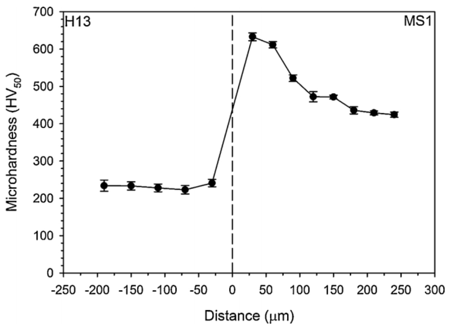
More complex scenarios are presented for dissimilar metals. One such example is the MS1–H13 hybrid produced by Laser Powder Bed Fusion (LPBF) [89], which features a microstructure comprising a large equiaxed grained matrix, oval precipitates on the H13 tool steel side, and ultra-fine martensite grains on the MS1 (LPBF) side. The H13 side of the MS1–H13 material exhibited a constant hardness value of 232 HVN throughout the section, whereas the hardness on the MS1 side was reported to peak at 644 HVN just after the interface (Figure 9), due to the Hall–Petch strengthening mechanism. This increase in hardness is likely attributed to the presence of fine martensite grains, which provide a greater number of grain boundaries and dislocations, which resist the motion of dislocations and enhance the material’s strength. In its as-built state, the MS1–H13 material exhibited a lower ultimate tensile strength of 644 MPa, which is 462 MPa less than that of the MS1 side. The failure occurred specifically at the H13 section with a dimple rupture. The lower strength in the H13 counterpart is attributed to the soft annealing heat treatment performed on the conventional H13 steel prior to the material’s use in AM [89].
An extension to the previous work [89] involved modifying a similar hybrid material through a heat treatment regime that included Solution Treatment (ST) at 815 °C and 915 °C for 15 min each, followed by aging at 490 °C for 360 min. The resulting material exhibited a uniform hardness averaging 600 HVN across the entire hybrid structure, which was attributed to the coarsening of lath martensite in the MS1 section and solid solution hardening in the H13 steel section [46]. The solution treatment temperatures used minimized the alloy segregation and produced hard martensite after quenching. The material’s yield strength increased to around 1860 MPa, but with a lower fracture strain of 5% compared to 23% in the as-built state. Interestingly, the fracture occurred near the interface, which was scarcely distinguishable from the rest of the hybrid material. Direct aging of the hybrid material produced mechanical properties almost similar to the as-built alloy, with fracture occurring in the H13 steel section [46]. These results differed from those reported by Cyr et al. [90], in which fracture occurred at the interface. In their study, the hybrid material was produced using LPBF and subjected to ST at 815 °C, followed by a 982 °C preheating for 1 h before aging at 490 °C for 6 h, based on the manufacturer’s specifications. This heat treatment procedure resulted in a peak strength of approximately 1700 GPa, owing to Orowan loop strengthening with the help of Co and Mo precipitates and the grain refining effect of Ti [91,92]. Non-conventional heat treatment protocols have also been adopted [47,55], whereby direct aging is used to avoid the loss of strength in a peak-aged hybrid base. An intact interface was obtained in both the as-printed and aged state. In the as-printed state, failure occurred in the printed material M789 at about 1100 MPa, and after aging, failure occurred in the N709 at approximately a 1600 MPa base plate. The effects of direct aging improved the strength of M789 by precipitation of the η-phase, at the same time minimizing the loss of strength in the hybrid base.
Based on the literature, developing an optimized heat-treatment schedule is crucial for achieving the desired mechanical behavior in a hybrid material system, regardless of the additive manufacturing technique used. It has been noted that individual heat treatment methods for each material may not provide the best combination of strength and ductility, as observed by Cyr et al. [90]. This is particularly relevant for AM maraging steels and wrought medium carbon steels, which can benefit from a well-designed heat treatment. The ideal heat treatment procedure should balance the strength and ductility of the hybrid material while eliminating microstructural inhomogeneities, which may vary depending on the specific hybrid material system. A systematic approach is required to arrive at an optimized heat treatment schedule based on the intended application.
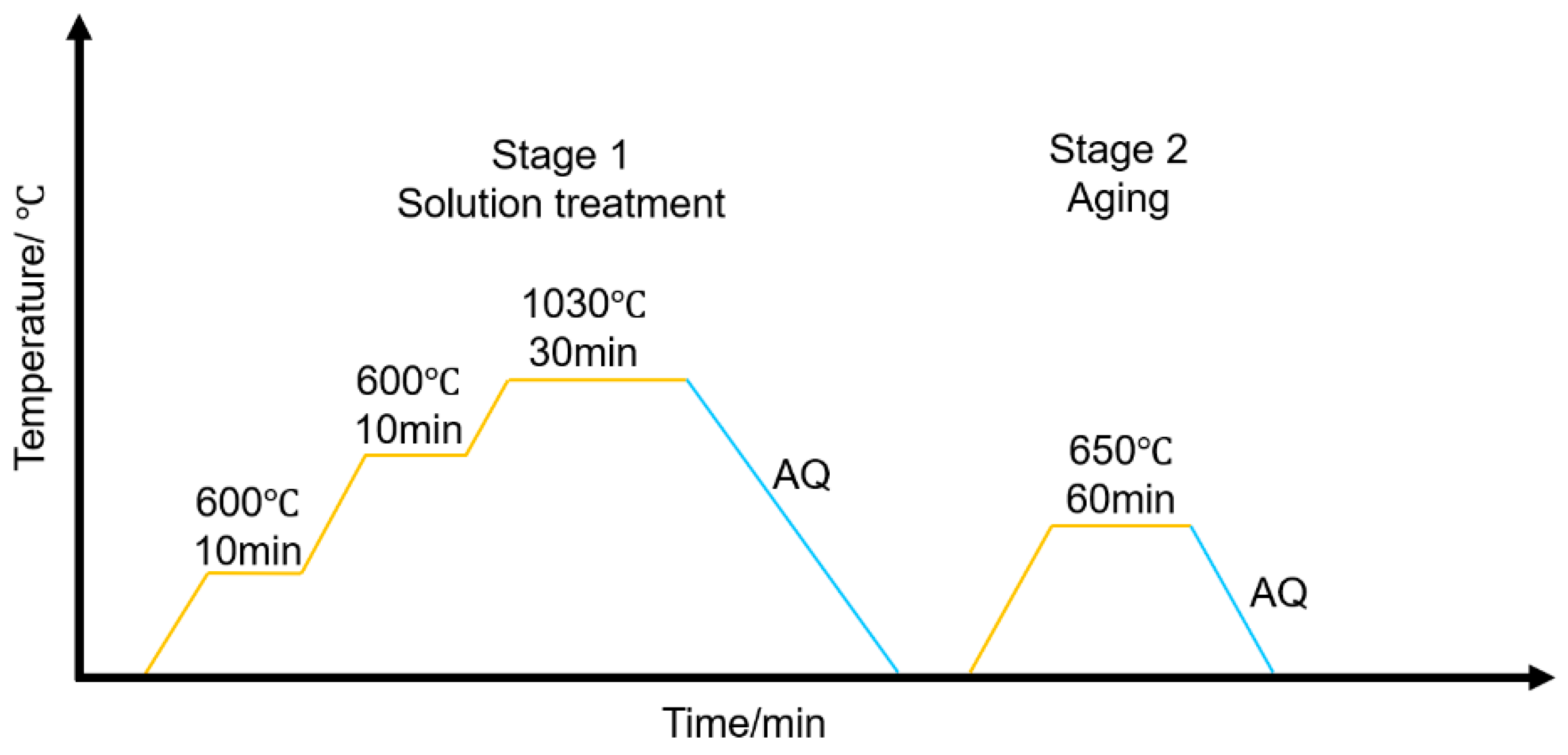
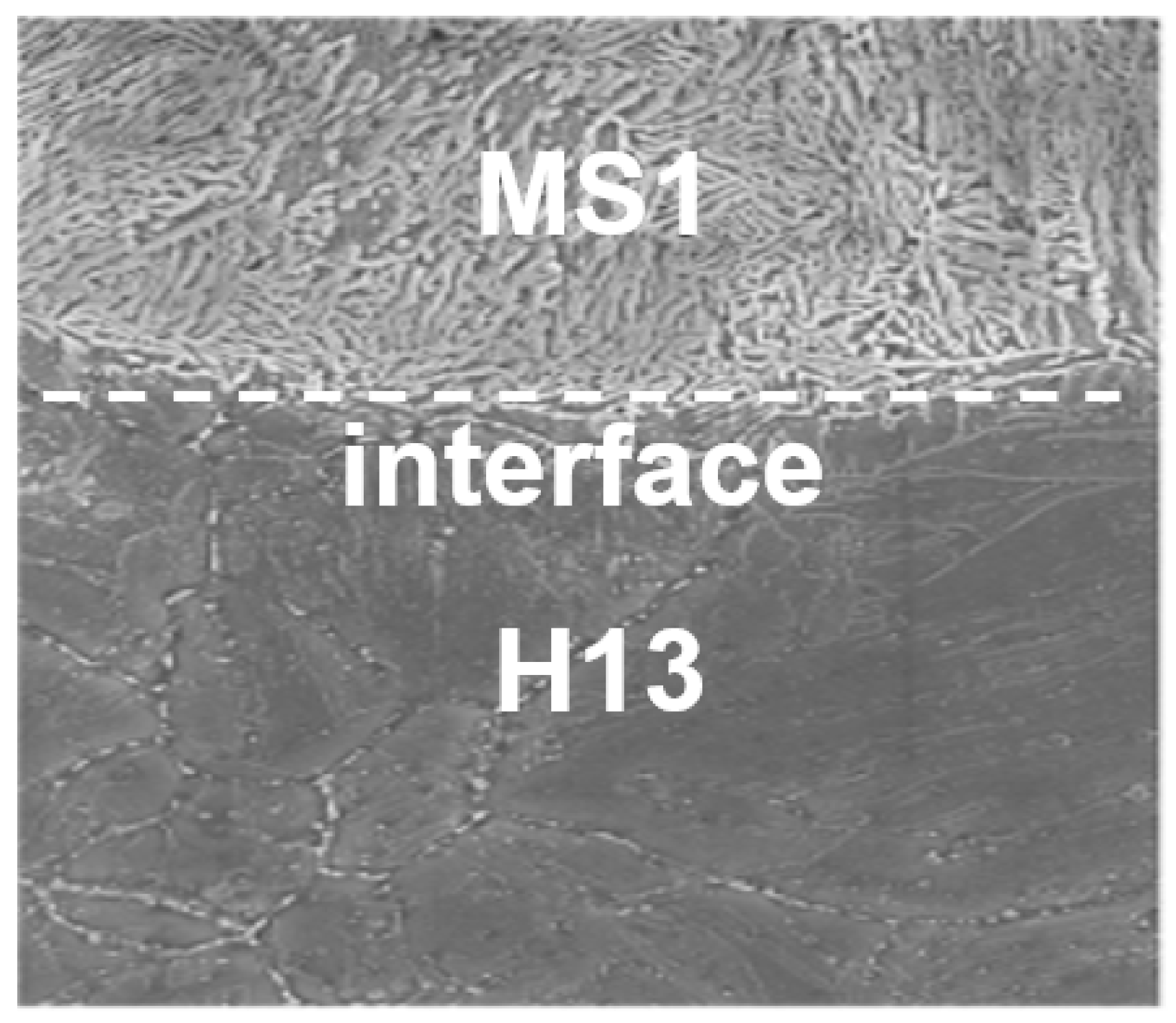
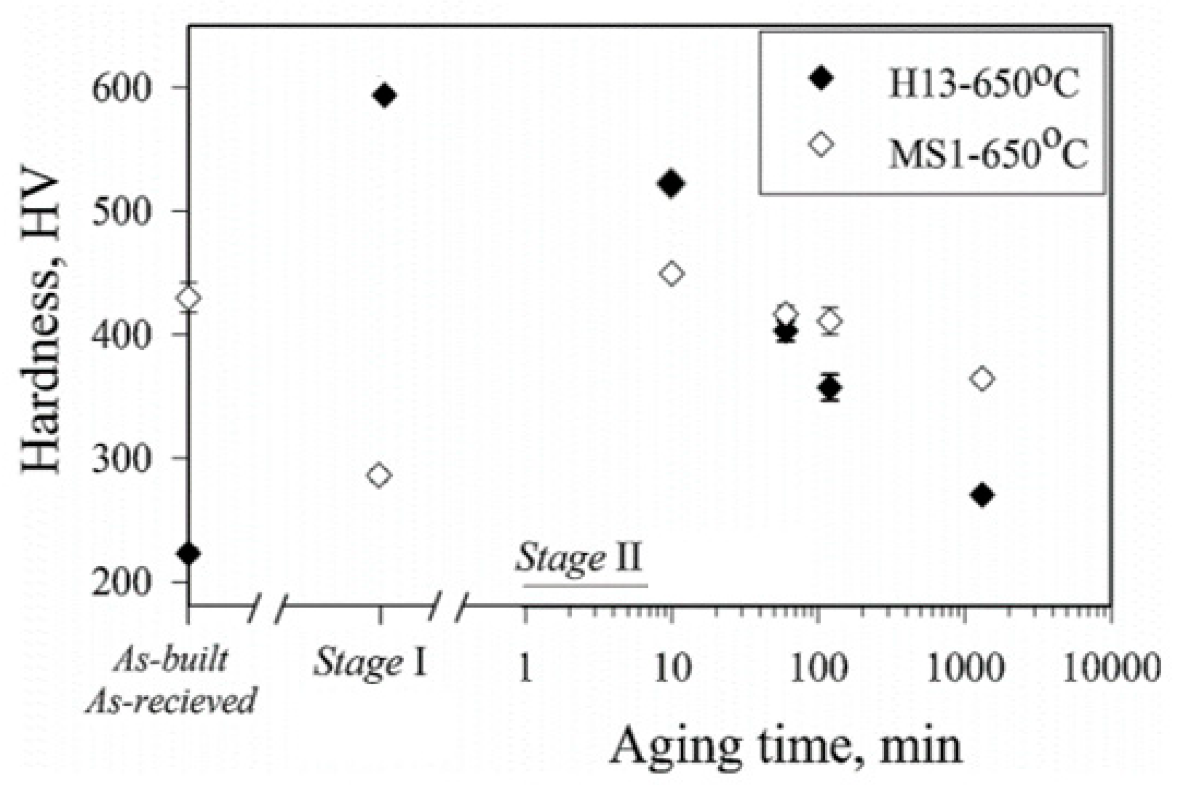
Aziz et al. [34] employed a combination of solution treatment and aging to modify the properties of a similar MS1–H13 hybrid material, as demonstrated in Figure 10. The resulting microstructure consisted of a coarse-grained H13 substrate and a fine-grained MS1 layer (Figure 11). The solution treatment involved heat treatment up to 1030 °C, followed by quenching, which caused the H13 alloy to revert to austenite and form a hard martensitic structure. The MS1 layer, on the other hand, experienced a reduction in hardness due to austenite formation. Aging at 650 °C for 60 min further enhanced precipitate formation and resulted in a maximum hardness of 420 HVN for MS1 and 520 HVN for H13, respectively. In the as-built state, the H13 layer had a lower hardness of 220 HVN than MS1, which averaged 420 HVN. The solution treatment improved the hardness of H13 to about 600 HVN and lowered the hardness of the AM layer, which is in agreement with the findings of Shakerin et al. [46] and LeBrun et al. [85]. Interestingly, this finding contradicts previous reports suggesting the formation of austenite, which typically has lower mechanical properties [16]. In the case of the H13 alloy, it contained approximately 0.40% C, which resulted in the formation of a hard and brittle martensitic structure after undergoing solution treatment. During tensile testing of the MS1–H13 hybrid material, the fracture occurred at a stress and fracture strain of approximately 1100 MPa and 11%, respectively. Before the fracture, a considerable amount of strain was concentrated in the dissimilar joint. The inhomogeneous microstructure resulted in strain concentration in the dissimilar joint. In conclusion, the impact of solution treatment on the two alloys varied. It caused H13 to revert to austenite and form a hard martensitic structure upon cooling. After solution treatment, MS1 experienced a reduction in hardness due to austenite formation while enhancing precipitate formation (Figure 12) [34].
The properties of an MS1–C300 hybrid material were compared in another study, where the C300 substrate was employed and the MS1 was deposited using LPBF. The individual hardness values of the MS1 and C300 after aging were found to be similar to the MS1–C300 hybrid material, with a peak value of 450 HVN achieved after solution treatment at 850 °C for 90 min, followed by aging at 650 °C for 10 min. During aging at 490 °C, it was observed that the hardness value continued to increase steadily beyond 67 h of aging time. The peak hardness was not determined, indicating that no over-aging had occurred. Mechanical testing of the MS1–C300 material after aging at 650 °C revealed a fracture in the MS1 portion with an ultimate tensile strength of 1200 MPa, which was 900 MPa higher than that of the individual C300 alloy aged at 490 °C. The optimal temperature for good mechanical properties was found to be 650 °C, which increased the hybrid material’s ductility to 10% due to a loss of strength at higher temperatures. The failure in the MS1 section was attributed to about a 10% lower flow stress and initial porosity, which facilitated void expansion and coalescence. Pore defects acted as stress concentration points, which exacerbated failure [21]. The strain was localized in the MS1 region after the peak strength was reached [34].
The studies mentioned above have shown that the primary objective of hybrid materials is to attain maximum hardness after adequate aging of the printed alloy and tempering of the conventional material to achieve uniform properties. However, there are still challenges involved in achieving the desired properties due to the different responses of various materials.

5. Effect of Heat Treatments in AM Processed Maraging Steels

The strength of maraging steels relies primarily on the presence and distribution of strengthening precipitates. The impact of these precipitates and how they affect the final strength of maraging steels are discussed.

5.1. Strengthening Mechanisms’ Models

The strengthening mechanism for maraging steels includes solid solution strengthening, dislocation hardening, and precipitation strengthening. In addition, the effect of these mechanisms may be utilized to evaluate the Vickers hardness and yield strength of maraging steels according to Equation (1) [92,93,94].
H v = 1 3 σ y = 1 3 ( σ s s + σ m a r t + + σ p )
where σ m a r t is the effective martensite strength, σ p is the precipitation strengthening, and σ s s is the contribution of solid solution strengthening.

5.1.1. Solid-Solution-Strengthening Model

The Fleisher equation is used to determine the critical resolved shear stress due to the substitution of solute elements by other alloying elements involved:
σ s s =   ( ( β i 2 x i , α ) 1 2 )
where x i , α is the atomic fraction of the element in consideration ( x i ) in the matrix and βi is the constant strengthening value that describes the lattice and modulus misfit of the element concerning the major element [95], which in this case is iron. Table 4 shows the iron values of several solution-strengthening constants for alloys studied by Nava et al. [92]. These values are based on the assumption of infinite solid solubility in iron. According to the values in Table 4, Mo and Ti give the strongest solid solution strengthening. With increasing particle volume fraction, the effect of the precipitate forming elements (Mn, Ni, Ti, Mo) decreases. The changes in   x i , α are determined by Equation (3).
x i , α = x i Σ x i j f j 1   f j
where f j represents the volume fraction of particle j and x i j is the volume fraction of element i in j [92].

5.1.2. Effective Martensitic Strength

Grain boundary area and dislocation density are contributors to the adequate strength of the martensite matrix in maraging steels [96]. The block size dblock (Figure 13) is considered the practical grain dimension and formulated in the form of the Hall–Petch relationship and the Taylor equation, which resolves the strength effect to the dislocation density [95].
The combined formulation is presented in Equation (4).
  σ m a r t = 300 d b l o c k + 0.25 M µ b ρ
where µ is the shear modulus, ρ is the dislocation density after solution treatment, b is Burger’s vector, and M represents the Taylor orientation factor. However, for the simplicity of calculations, dblock is assumed to be constant, despite reports mentioning the existence of small variations in the sizes even in aged conditions [96,97]. The low distortions are due to low lattice distortions and the high solubility of solute elements [95].

5.1.3. Precipitation Strengthening

The presence of precipitates hinders dislocation gliding. They act as obstacles, which reduce their mobility, hence reducing slip and grain boundary sliding. Based on the size of the precipitate and its coherency inside, the matrix dislocations have two main ways of passing these obstacles, viz. bowing (Orowan–Ashby model) [98] and shearing (Friedel model) [99] the precipitates, Equations (5) and (6), respectively.
  σ p = 0.26 µ b r P f 1 2   l n ( r P b )
σ p = 1 b 2 S π w q ( γ   w r r p S ) f 3 2 r p
where rp is the particle radius (this model assumes that particles are spherical), S is the dislocation line tension (µb2/2), wr and wq are particle statistical constants [100], γ is the antiphase boundary energy associated with the sheared precipitates, and f is the fractional volume of precipitates. In the case of maraging steels, the pile-up model by Ansell and Lenel assumes that yielding will occur after a critical number of dislocations’ pile up exceeding the maximum stress [101] (Equation (7)). The Orowan–Ashby model and the modified Orowan–Ashby model [102] (Equation (8)) are considered to be the most-relevant, according to Niu et al. [95]. In contrast to Schnitzer et al. [97], the Orowan and the Friedel models had good fitting results with experimental results based on a PH 13-8Mo stainless steel under aging and overaging conditions.
σ p = 2 µ 4 C ( f 1 3   0.82 f 1 2   )
σ p = 2 µ b ϕ l n ( d 2 r p 2 b ) 4 π ( d r p )
where µ’ is the shear modulus of the precipitates, C is a constant, d is the inter-particle spacing, and Φ is related to the Poisson ratio (ν) by the following relationship: Φ = [1 + 1/(1 − ν)]/2. The previously mentioned scenarios assume that only one form of precipitate exists, which is not the case as purported by Nava et al. [92]. Ni-Ti-rich clusters were associated with Mo-rich phases. According to Ardel [102], the total precipitate strength is the summation of each particle’s contribution, represented by Equation (9).
σ p = ( j σ j 2 ) 1 2
where σj is the strength increase due to precipitate j with f and r, following Equations (5) to (8).
There are limitations in using these precipitation models (Equations (2)–(9)) [103], as their exact contribution of precipitation to strength is difficult to determine because their exact interplanar spacing is not accounted for from the volume and fraction sizes and the lattice misfits between the matrix and precipitates. For example, it was shown that the Orowan model outputs different magnitudes with a factor of 10 in some instances based on the type of distributions used [95]. In the case where several mechanisms are expected to proceed with different precipitates sizes, Schnitzer et al [101] suggested that no single model can account for the peak hardness. Hence, based on the precipitate sizes, strength can be estimated by the shearing model below a critical size value and the Orowan model above this value. The previously mentioned Ansell and Lenel model can be used to describe the contribution of fine precipitates; however, the model is appropriate for a constant volume fraction. To accommodate varying precipitate sizes during different aging times, a new formulation (Equations (10)–(12)) is better suited.
Δ σ O r o = 0.81 M T G b l n 2 r s b 4 π r s [ ( π 4 Φ ) 0.5 1 ] ( 1 v ) 0.5
Δ σ β = m i n ( Ω β , Oro |   κ β r a t i o Ω β , sh )
Δ β , Oro = ( Φ ) 0.5 0.81 M T G b l n 2 r s b 4 π r s [ ( π 4 Φ ) 0.5 1 ] ( 1 v ) 0.5   Δ σ β , Sh = ( Φ ) 0.5 2 M T S b r ( π r ω q ) 0.5 ( π r ω r Υ S ) 0.5
where r s = ( 2 3 ) 0.5 r , MT is the Taylor factor, G is the matrix shear modulus, b is the magnitude of the dislocations of Burger’s vector, ν is Poisson’s ratio, ω, q, and r are constants derived from particle statistics, S is the dislocation line tension given by S = Gb2/2, and r and Φ are the particle radius and volume fraction, respectively.
This was used to determine the strength contribution of NiAl precipitates in a 9922 alloy (maraging steel) undergoing shearing and Orowan looping. The precipitate sizes were normalized with a standard deviation of one under the assumption that the overall strength is a combination of the two mechanisms. In addition to precipitate strengthening, the increase in the strength of maraging steels involves contributions from the lath structure ( σ l ), the intrinsic strength of iron ( σ F e ), and Solid Solution strengthening (SS). As a limitation of most models, the contribution of the SS is not well defined. Various researchers have identified different relationships between the composition (χ) of solute elements and the resulting strengthening in maraging steels. These relationships often exhibit varying values of the composition exponent, with commonly used values being 1 or 1.5. Additionally, different proportionality constants are used [104,105]. The strengthening varies in a complex way with changes in the elemental concentrations.
The contribution of these factors is represented in Equations (13) and (14). The hardness of the lathe structure and Fe matrix is also included.
Δ σ s s ( H V ) = 14.5 x A l + 14.5 x M o 4.5 x N i + 14.5 x w
σ 0 = σ F e + σ l
For the 992 alloy, the size and distribution of precipitates was determined using Atomic Probe Topography (APT) and Small-Angle Neutron Scattering (SANS), and the overall strength can be represented as shown in Equation (15).
σ Y = σ 0 + Δ σ s s + κ L Δ σ O r o   +   κ β Δ σ ß
κL, κβ, and κβratio are fitting variables.
The results of this model (Figure 14) showed that the strengthening via the Orowan model decreases with extended aging time because of precipitate coarsening. A noticeable jump in the NiAl precipitate was observed based on the SANS measurements. The estimated strength contribution of the Laves phase was difficult to determine as evidenced by the small-sized precipitates reporting a similar hardness with the precipitates with a large size fraction. Solid solution strengthening decreased with the aging time because of the diffusion of strengthening elements towards the Laves phases. This suggests that the growth of the Laves phases is faster at higher temperatures, and hence, the contribution of the solid solution to the overall hardness is expected to diminish at higher temperatures. In contrast, at low aging times, the NiAl precipitates, along with other intrinsic strengthening contributions such as solid solution, lath structure, and matrix effects, play a dominant role. However, at extended aging times exceeding 50 h, the dominance shifts to the formation of Laves phases. Some discrepancies can be observed for this model as it shows that the peak strength at 560 °C is lower (475 HV) than the experimental value (520 HV) at a total aging time of about 50 h. Conversely, the predicted hardness is higher than the actual value at 520 °C. The model failed to predict the complete behavior, potentially due to errors from the acquired SANS data.
Better predictability can be achieved by isolating the phases and studying the dominant strengthening mechanism for each phase at different aging temperatures and how it relates to the volume size and fraction. To isolate the strengthening effects of different phases, Reference [106] used APT to calculate the spacings between the precipitates and to determine the contribution of the β and η strengthening phases in Fe-12Ni. In this study, two models were used. Model 1 included the contribution of the grain size, dislocation density, and solid solution strengthening. This was later used to validate the results from Model 2, which incorporates the mean free radius and distance and the surface-to-surface distance of precipitates as measured from the APT data. It was found that the precipitation strengthening of the combined βand η phases was close to 1000 MPa at an aging temperature of 510 °C for 16 h and that the relative strengthening effect of each phase was sensitive to the Ti and Al concentration. Low titanium concentrations (approximately 1 wt.%) and high Al concentrations (approximately 1.6 wt.%) in the β phase contributed more to the overall strength compared to high Ti concentrations (approximately 1.5 wt.%) and Al concentrations (0.9 wt.%).
In the case of more complex microstructures, such as those observed in LPBF–Corrax [107], precipitation strengthening was found to be the main contributor to strength via the shearing mechanism. Three factors can be considered to contribute to the overall strength according to Equation (16) [108].
Δ σ = Δ σ o + Δ σ c + Δ σ m  
where Δσo is the order strengthening, Δσc is the coherency strengthening, and Δσm is the modulus mismatch strengthening. Order strengthening arises from the antiphase boundaries during dislocation shear through the ordered ß-NiAl, and it is expressed as:
Δ σ 0 = 0.4 M ϒ APB b ( 3 π f 8 ) 0.5
where ϒAPB is the antiphase boundary energy of the precipitates. M is the Taylor factor, and f is the volume fraction of precipitates.
Coherency strengthening, which arises from the mismatch strain between the coherent precipitates and the matrix, is given by:
Δ σ c = 2.6 M ( ε G ) 1.5 ( 2 r f Gb ) 0.5
where r is the precipitate mean radius and ε is the lattice mismatch parameter.
Lastly, the modulus mismatch strengthening arises from the variation in the dislocation energy as dislocations approach a precipitate with a different shear modulus to the matrix:
Δ σ m = 0.0055 M ( Δ G ) 1.5 ( 2 r f ( Gb ) 0.5 ) 0.5 b ( r b ) 1.5 m 1
where ΔG is the shear modulus mismatch between the precipitate and matrix (G and Gp, respectively) and m is a constant (0.85).
The estimation of the final yield strength was estimated to be about 1530 MPa as a contribution of the hierarchical structure of the microstructure. However, based on [101,103] previously discussed, the volume and size fractions need to be considered over the aging times for a more-accurate representation, in addition to the contribution of the high dislocation densities in AM parts.
Maraging steels are highly valued for their combination of strength, toughness, ductility, and weldability. Heat-treatment procedures can be used to optimize their properties by controlling the precipitation of intermetallic phases within the low-carbon Fe-Ni/Mn martensitic matrix. Additive manufacturing offers a unique platform for producing maraging steels with tailored microstructures and mechanical properties [6,109,110]. One common approach is to homogenize the material by solution treatment, followed by aging at a lower temperature to promote the precipitation of nanoscale intermetallic phases such as Ni3(Mo, Mn, Al) and Ni3Ti [111,112]. The choice of alloying elements plays a critical role in determining the mechanical properties by influencing the type of intermetallic phases formed. The nucleation and growth of precipitates are dependent on the segregation energy and the degree of diffusion of the solute atoms involved. The interaction energy associated with the alloying elements is expressed by Equation (20). This formula can be used to determine the tendency of elemental segregation.
Δ E A B = E   ( A + B ,   N 2 ) + E ( N ) + E   ( A ,   N 1 ) + E   ( B ,   N 1 )
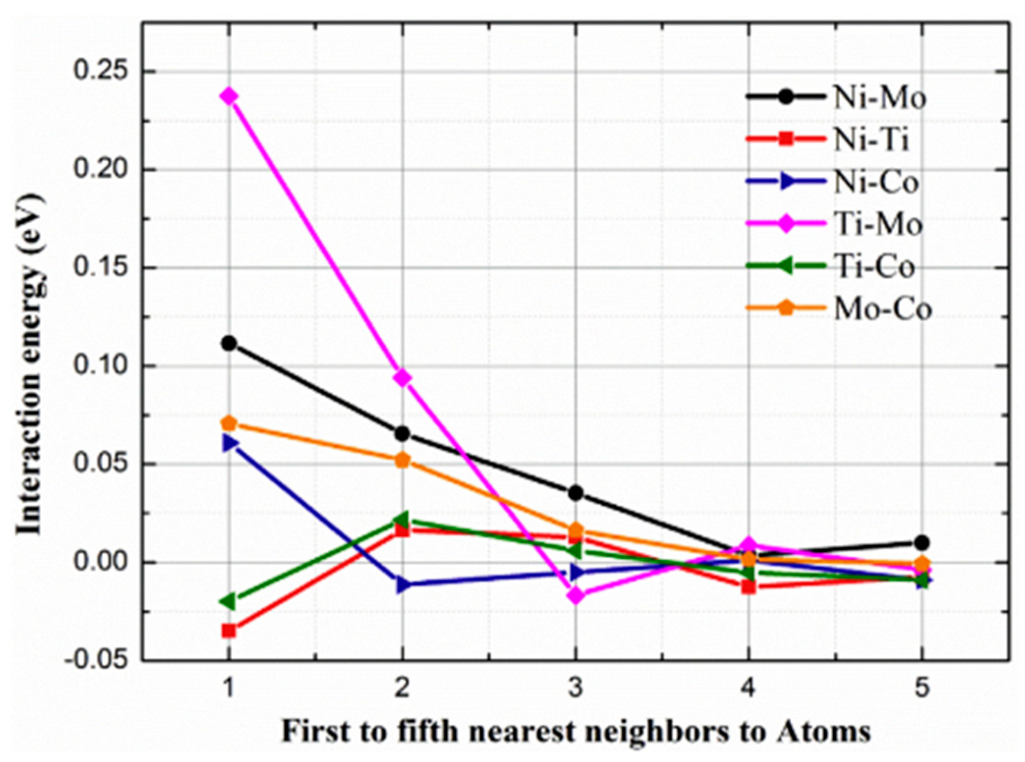
where E (A + B, N − 2) is the supercell energy for two different solutes located in different nearest neighbor positions and N − 2 is the major alloying element atoms (Fe in the case of maraging steels). E(N) is the supercell energy with N number of Fe atoms. E (A, N − 1) and E (B, N − 1) are the supercell energies associated with A and B solute atoms and (N − 1) Fe atoms. As demonstrated in Figure 15, the research of Niu et al. [95] showed the variance of the interaction energy between different solute combinations. The interaction energy between elements that are further away is lower compared to elements in the vicinity. As a result, the interaction energy between Ni and Co at the second nearest neighbor is negative (Figure 15), implying that Ni will be attracted to Co’s second nearest neighbor. The interaction energy between Ti and Co is also negative at the first nearest neighbor position (Co), resulting in the mutual attraction of Ti and Co during the aging. In the case of the Ti-Mo and Ni-Mo systems, the nearest atom interaction energies are positive, indicating a tendency for Mo repulsion from the Ni-Ti-rich clusters. Additionally, the third nearest neighbor energy for Ti-Mo is negative, suggesting that Mo atoms will be excluded from the Ni-Ti-rich clusters and, instead, form a separate Mo-rich phase. Due to the relatively low aging temperatures employed in the study (480 °C), the diffusion of Mo is slow, which explains the absence of a Mo-rich phase in the early stages of aging. However, as the aging process advances, it was observed that a Mo-rich phase started to nucleate at the interface between Ni3Ti and the matrix.
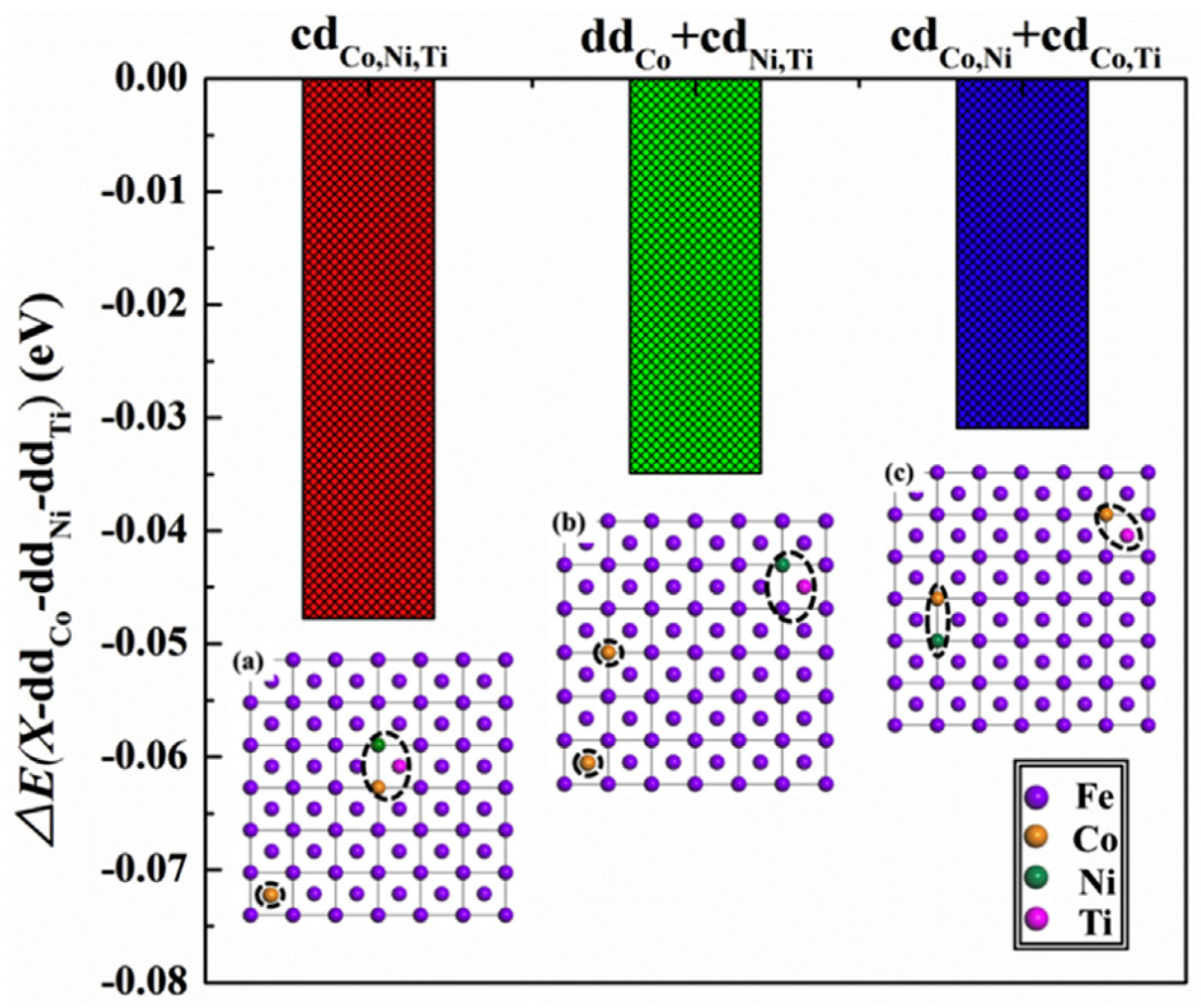
Due to the low interaction energies between Ni, Ti, and Co, these elements are closely associated with each other. The combination of these elements during aging can be classified into three potential categories (refer to Figure 16):
  • (a) All three elements form a cluster distribution (cd);
  • (b) Ni and Ti combine to form a cluster distribution in the iron-rich region (cd), resulting in Co being dispersed (dd);
  • (c) Co, in turn, forms clusters with Ni and Ti.
The stability of each of these possibilities may be compared to the dispersed distribution of alloying elements, which can be expressed using Equation (21).
Δ E ( X d d C o d d N i d d T i ) = ( E X E F e C o E F e N i E F e T i )
where Ex is the distribution energy of the involved elements in this case (Ni, Co, and Ti), EFe−Co, EFe−Co, and EFe−Ti are the energies associated with the dispersed distribution. The lowest energy state is when all three elements form a cluster together. Since Ni and Ti have the lowest interaction energy, they tend to nucleate in the form of Ni3Ti with an association of Co and Fe atoms with formation energies similar to the Ni and Ti sites. The formation energy can be represented by Equation (22).
E f = n E N i 3 T i F e / C o ( ( 3 4 n )   o r   ( 3 4 n 1 ) ) E N i ( ( 1 4 n 1 )   o r   ( 1 4 n ) )   E T i E C o / E F e
where nENi3Ti−Fe/Co is the energy of the supercell with one Co or Fe atom, 3/4n or (3/4n − 1) is the bulk energy of Ni atoms, and (1/4n − 1) or 1/4n is the bulk energy of one Co or Fe atom. Figure 16 shows that, regardless of Co’s and Fe’s occupied Ni and Ti sites, the formation energy of Ni-Ti clusters is less endothermic, and as aging progresses, Co and Fe will be rejected from Ni3Ti.
For example, in the early work by Lang et al. [113], high-Ni-content-based maraging steels with Ti led to the precipitation of Ni3Ti phases. Partial substitution of the Ni by Fe and Co in some sublattices was also reported, together with the formation of Fe2Mo phases at extended aging treatments [110,113]. This is consistent with the results of Tian et al. [93] and Bai et al. [114] on the Heatvar alloy and 18Ni-300, respectively. In the latter study [114], it was observed that heat treatment led to variations in both mechanical and microstructural properties. Surprisingly, Directly Aged (DAG) samples and Solution treatment followed by Aging samples (SAG) displayed a comparable hardness (654 HVN) and tensile strength (2126 MPa), despite their distinct microstructures. Austenitization above 900 °C resulted in the growth of austenite grains, producing large lathe martensite, and solution treatment facilitated the migration of segregated Mo and Ti into the grain, causing the Mo- and Ti-rich white grain boundaries to disappear. Previous studies, by Aboulkhair et al. [115], also observed the disappearance of alloy-rich grain boundaries after solution treatment. However, white borders with high Mo and Ti content were seen in the grain boundaries compared to the DAG samples. This suggests that the maximum temperature used for aging (560 °C for 12 h) did not provide sufficient energy to diffuse Mo and Ti from the grain boundaries into the grain interiors. For maraging steels generated by LPBF, solution treatment may be unnecessary, and a direct aging strategy can be utilized due to the rapid cooling (103 to 108 K/s [16,116]) during processing, which produces lathe martensite. While employing DAG may be a cost-effective option for post-heat treatment of maraging steels generated by additive manufacturing, this may not always be true [114,117]. Solution treatment is known to improve ductility and reduce micro-segregation, and achieving a good balance of ductility and strength is crucial for practical applications. However, at extended periods, it can cause the reversion of martensite into austenite [85]. Additionally, residual stress from additive manufacturing processes can adversely affect mechanical performance [12]; therefore, solution treatment is deemed a necessary step. It is worth noting that this study failed to clearly explain the response of martensite lathes’ size to different heat treatments, which is a crucial factor in establishing the effectiveness of each heat treatment procedure.
In a previous study by Jägle et al. [110] on 18Ni-300 steel, it was found that localized heating during the AM process did not result in phase transformations due to the rapid heating/cooling. However, after aging at 480 °C for 5 h, three main phase precipitates were observed, namely (Fe,Ni,Co)3(Ti,Mo), (Fe,Ni,Co)3(Mo,Ti), and (Fe,Ni,Co)7Mo6 (µ-phase). Atom probe tomography results identified the existence of two Ni3X phases, with one phase having a lean Ti concentration compared to Mo in a ratio of 1:3 and the other phase having a lean concentration of Mo compared to Ti in a ratio of 1:3. Reverted austenite was suggested to be present in the Ni-rich patches detected in the precipitate-free zone. The equilibrium concentration of austenite at 480 °C was calculated using thermodynamic calculations and was confirmed through experimental validation. The study observed theoretical and empirical deviations in Ni concentrations for the martensite, with 4 at. % and 10 at. %, respectively. The cause of this discrepancy was not clear, as it could have been due to the precipitation of the new intermetallic or slow diffusion of Ni [110].
Allam et al. [118] focused on increasing the number density of intermetallic precipitates to improve the homogeneity of 300 maraging steel produced using LPBF. The absence of nano-precipitates in the as-printed state was confirmed by the earlier findings by Jägle et al. [110]. The authors suggested that Ni segregation under direct aging at 510 °C for 6 h possibly reduced the potential active sites for nucleation, favoring growth over nucleation. On the other hand, solution aging (900 °C for 1 h + 510 °C for 6 h) promoted fine precipitates with significant density, limiting austenite reversion [118]. These findings can expand the ability to control the different mechanical properties of materials by adjusting the volume density of precipitates. In contrast to the findings of Bai et al. [114] and Thorsteinsdóttir et al. [117], the results obtained in this study demonstrated that solution treatment is an essential step for effectively managing and controlling precipitation, as well as achieving the desired mechanical properties.
Tian et al. [93] conducted a study on the Heatvar alloy, comparing the effects of solution and DAG on the precipitates’ evolution in the as-printed state. The study found that the alloy exhibited a Laves phase during solidification along the melt pool boundaries where Mo was segregated. At ambient conditions, this phase was found to possess brittleness, making it prone to act as crack nucleation sites [119]. A theoretical equilibrium partition coefficient of 0.34 and a solid front velocity solidification averaging 0.5 m/s confirmed this observation together with early reports on Fe-Mo systems [109]. To address this issue, solution treatment was conducted, which simultaneously dissolved the eutectic phase and improved the alloy’s elongation from approximately 4% to 15%. The solution treatment was carried out at an elevated temperature of 1233 K for 30 min, which ensured the redistribution of alloying elements inside the grain interior.
M6C and MC carbides were identified, consistent with Liu et al.’s work [120], who confirmed the observations. These carbides provide sufficient strength and ductility to the alloy. A comparison of the as-printed and solution-treated samples showed a good balance of the strength and ductility in the solution-treated samples, making the heat treatment suitable for low-strength, high-ductility applications. Direct aging at 903 K for 240 min resulted in the highest strength value, averaging 1980 MPa. During the aging of maraging steels, Fe2Mo precipitates with a size of approximately 36 nm were formed [120], which were confirmed by TEM analysis. The disappearance of previously observed melt pool boundaries was also observed, similar to the solution-treated samples. The most-complex material was produced with a distribution of around 20% precipitates and a hardness of over 2000 GPa. However, there was a considerable loss of ductility of 13% EL compared to the ST samples due to the production of hard precipitates, as shown in Table 5.
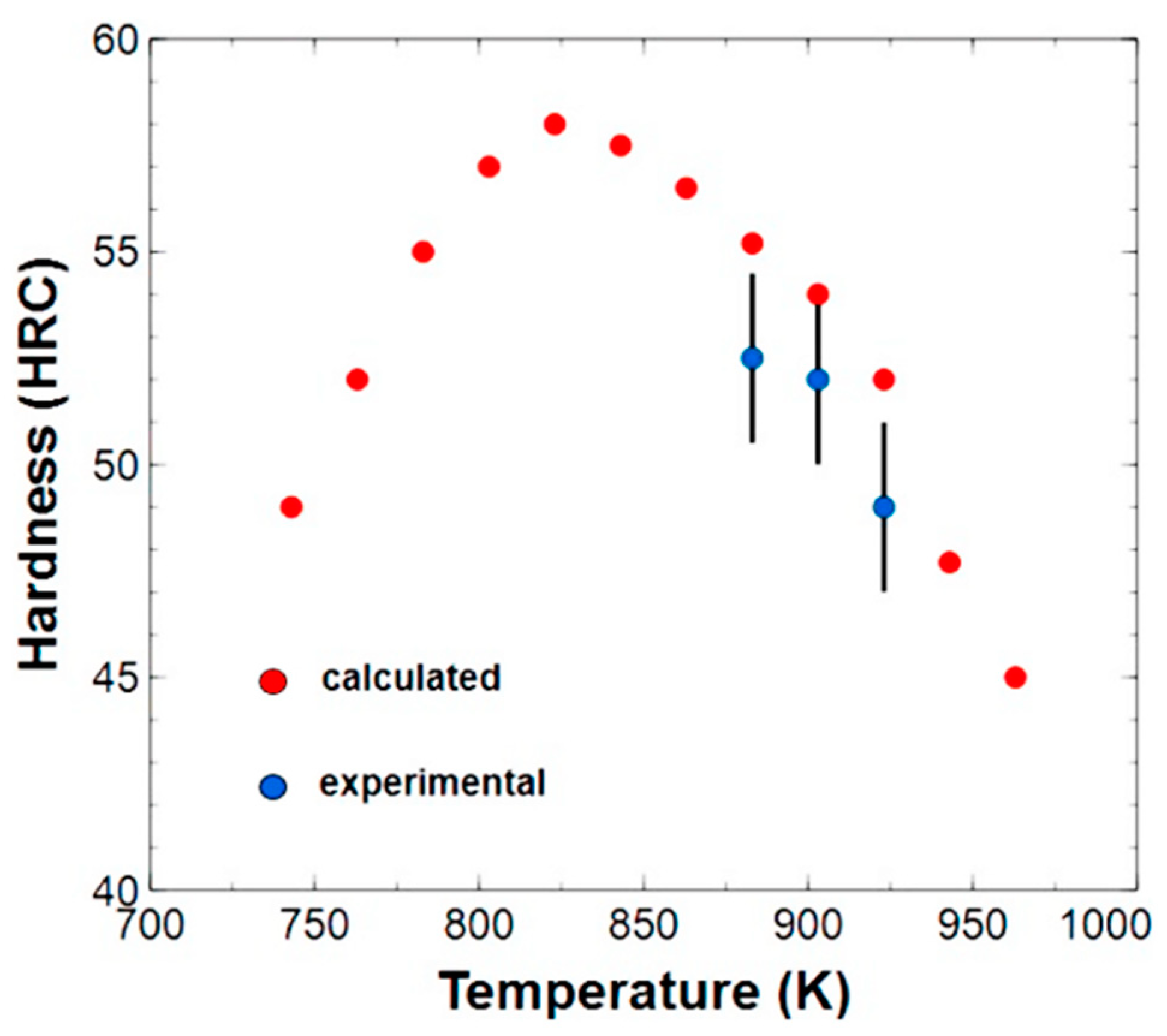
To gain a better understanding of the effect of aging temperature on strength, aging at temperatures of 883 K, 903 K, and 923 K, based on the Lifshitz–Slyozov–Wagner (LSW) model, was simulated. Unlike other alloying systems, aging was found to cause severe negative drops in the mechanical properties. However, the Heatvar alloy showed a minimal reduction of only 2 HRC after being aged, indicating excellent high-temperature properties. In contrast to other LPBF alloy systems previously studied, such as MS1, which produces a soft austenite phase at elevated aging temperatures due to over-aging, Heatvar exhibited superior mechanical stability at a temperature of 893 K for 100 h (Figure 17). Beyond this optimal temperature, Orowan looping became more pronounced as the precipitates coarsened. Previous studies on wrought H13 and MS1 showed significant drops in the HRC values [93], demonstrating the Heatvar alloy’s superior mechanical properties. However, this study did not address the combined method of applying solution treatment and DAG to optimize the alloy’s ductility-versus-strength ratio. Further research is needed to analyze the effect of solution treatment before aging and the results of aging time at different temperatures, as in the previous work by Bai et al. [114]. To maximize the mechanical and functional qualities of alloys, the development of an optimal HT method is crucial. Different heat treatment procedures with the same chemical composition may produce different reactions under similar chemical compositions.
An LPBF-EOS SS CX alloy and a wrought alloy belonging to the PH13-8Mo was reported [98] to possess a martensitic structure with a distribution of austenite as a result of austenite stabilizing elements (Mo, Ni, and Mn). Moreover, these elements decreased the martensite finish temperature. The fraction of retained austenite in the LPBF and the wrought alloy was 6% and 3%, respectively. Due to limited energy and time for the austenite-stabilizing elements to diffuse out of the austenite phase during the cooling process, significant elemental segregation was observed [118].
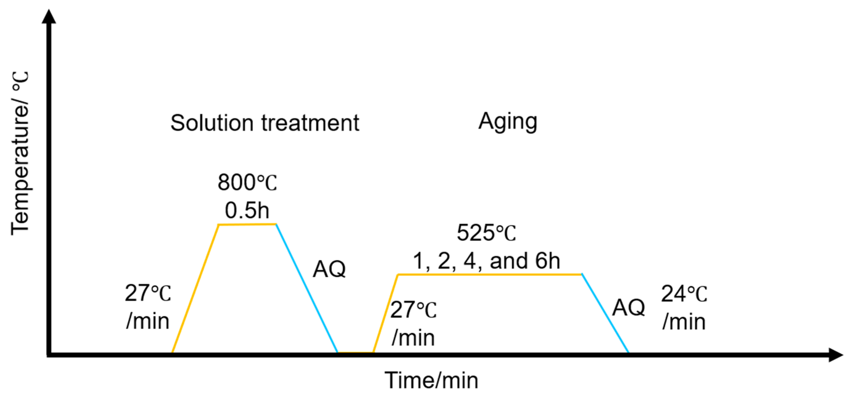
A similar solution treatment protocol was applied to the hybrid materials [98], consisting of heating at 850 °C for 30 min (Figure 18). A peak hardness of 50 HRC was achieved for both alloys after 2 h of aging. In this study, the LPBF alloy precipitated a larger (100 nm) NiAl phase and less reverted austenite (1%) compared to the wrought counterpart, which had a smaller (<40 nm) NiAl phase and approximately 5% retained austenite. This difference in reverted austenite could be attributed to the influence of nitrogen gas during powder atomization, as reported by Meridith et al. [121] in their work on PH17-4. The LPBF alloy exhibited a superior yield strength of 1700 GPa compared to the wrought alloy’s yield strength of 1600 GPa. In contrast, the wrought alloy exhibited reduced ductility of approximately 4% compared to 10% for the LPBF alloy. This highlights the significance of investigating the substantial retainment of austenite, as suggested by Troitter et al. [122], in order to better understand the underlying factors contributing to the mechanical properties of these alloys.
LPBF metals produce fine grain structures that strengthen metals due to a high grain boundary following the Hall–Petch mechanism, hence a higher yield strength [16]. Based on these observations, an ideal balance of precipitate size, reverted austenite, temperature, and aging time requires more understanding to tailor specific properties. Both alloys exhibited different microstructures and sensitivities to the applied heat treatments despite having similar compositions. The joining of dissimilar metals poses a significant challenge in the design of heat treatment schedules, as eluded earlier on [34,46]. Dissimilar joints of maraging steel (250) and PH 13-8Mo studied by Murthy et al. [50] exhibited the best strength of 1528 MPa, after a post-weld HT of 510 °C for 4 h followed by air cooling, attributed to the presence of Ni3Ti, Ni3Mo, and β-NiAl precipitates.
The presence of precipitates in the maraging steel was not systematically quantified, but inferred from the observed improvement in hardness after heat treatment, which peaked at 600 HVN. The PH 13-8 Mo HAZ (where the failure occurred) exhibited a mixture of martensite and reverted austenite, which lacked NiAl precipitates. The absence of precipitates enhanced the failure through dislocation lodging [96]. The low hardness (450 HV) and potential elemental segregation were identified as leading factors contributing to the challenge of joining dissimilar metals. A similar alloy system was modified by performing different welding techniques, such as GTCAW and Laser Beam Welding (LBW), which have similarities to LPBF and Electron Beam Welding (EBW). All joints using the different welding techniques demonstrated high tensile strengths above 1500 MPa after heat treatment [123]. The materials yielded the greatest strength of 1649 MPa and 1656 MPa for LBW and EBW, respectively, due to the presence of uniformly distributed Ni3Ti, Ni3Mo, and -NiAl precipitates (510 °C for 4 h). In contrast, a lower heat treatment of 485 °C for 3.5 h (with air cooling) resulted in lower strength measurements of 1490 MPa (GTCA), 1600 MPa (LBW), and 1610 MPa (EBW). The E/LBW failure occurred at the weld zone, with a fine dendritic structure. The failure was attributed to Ti and Mo elemental segregation near the interdendritic borders [118,123]. According to this study, an increase in aging time and temperature increases the mechanical characteristics of the parent alloys, despite failure in the joined section. This work did not determine the upper heat treatment limit to obtain the highest mechanical properties. In addition, solution treatment can be applied post-welding to minimize elemental segregation at the interface.

6. Conclusions

In this review, we presented the use of hybrid additive manufacturing and its progress over the past decade. The term hybrid additive manufacturing refers to processes that are used in conjunction with an additive manufacturing process in situ or post-printing to improve the quality of the final product or the production process. This review identified several processes as given in the literature with a focus on the use of AM as a joining technique for metals. Direct joining, gradient joining, and inter-layer joining were identified as the main joining techniques that produce interfaces with unique chemistry and mechanical properties. Poor bonding at the interface was a major concern, and the robustness of the interface was found to be governed by alloy compatibility, interface reaction products, and thermal conductivity. Solubility between metals is crucial to avoid segregation due to a lack of solubility. Furthermore, mismatched thermal coefficients and chemical compositions result in accumulated stresses and detrimental phases at the interface, respectively. These parameters contribute to the lack of fusion in joints and premature failure. Hybrid AM was identified as an alternative low-cost production option that can be achieved in the AM of maraging steels by printing on a low-cost substrate material. This reduces the quantity of printable material. In addition, dissimilar metal AM offers customized functionality to meet specific design requirements. However, careful design of the post-processing heat treatment is necessary to ensure good metallurgical bonding at the interface, as well as for the individual materials. Based on the literature surveyed, there is lack of a systematic way of optimizing the heat treatments of the dissimilar metals and their interfaces. The heat treatments are specific for individual materials and often compromise the strength of the interface. The growth of hybrid additive manufacturing for steels depends on the development of competent and specific heat treatment protocols, which are to meet the growing demand for multimaterials in industry. It is evident that multimaterials are crucial for productivity and efficiency, and hybrid AM is a promising field. There is a need for more understanding of the potential afforded by hybrid additive manufacturing.

Author Contributions

Conceptualization, K.N. and C.A.J.; methodology, K.N. and C.A.J.; validation, C.A.J., R.P., Y.T. and J.P.; formal analysis, K.N., C.A.J., R.P. and Y.T.; investigation, K.N.; resources, C.A.J.; data curation, K.N.; writing—original draft preparation, K.N.; writing—review and editing, K.N., C.A.J., R.P., Y.T. and J.P.; visualization, K.N., C.A.J., R.P., Y.T. and J.P.; supervision, C.A.J.; project administration, C.A.J.; funding acquisition, C.A.J. All authors have read and agreed to the published version of the manuscript.

Funding

This research was funded by the Natural Sciences and Engineering Research Council of Canada (NSERC) (ALLRP 560425-20, ALLRP 571059-21, RGPIN 04006), Canada Foundation for Innovation (CFI) (38944), Atlantic Canada Opportunities (220835), and the New Brunswick Innovation Foundation (NBIF) (EP2021-005, RAI2021-016).

Institutional Review Board Statement

Not applicable.

Informed Consent Statement

Not applicable.

Data Availability Statement

The data are available upon request due to restrictions, e.g., privacy or ethical.

Acknowledgments

The authors acknowledge with gratitude the funding received from the Natural Sciences and Engineering Research Council of Canada (NSERC), the Canada Foundation for Innovation (CFI), Atlantic Canada Opportunities and the New Brunswick Innovation Foundation (NBIF).

Conflicts of Interest

The authors declare no conflict of interest.

References

  1. Cardullo, P.; Kitchin, R. Smart Urbanism and Smart Citizenship: The Neoliberal Logic of ‘Citizen-Focused’ Smart Cities in Europe. Environ. Plan. C Polit. Space 2019, 37, 813–830. [Google Scholar] [CrossRef] [Green Version]
  2. Klocke, F.; Arntz, K.; Teli, M.; Winands, K.; Wegener, M.; Oliari, S. State-of-the-Art Laser Additive Manufacturing for Hot-Work Tool Steels. Procedia CIRP 2017, 63, 58–63. [Google Scholar] [CrossRef]
  3. Parupelli, S.; Desai, S. A Comprehensive Review of Additive Manufacturing (3D Printing): Processes, Applications and Future Potential. Am. J. Appl. Sci. 2019, 16, 244–272. [Google Scholar] [CrossRef] [Green Version]
  4. Tian, Y.; Palad, R.; Aranas, C. Microstructural Evolution and Mechanical Properties of a Newly Designed Steel Fabricated by Laser Powder Bed Fusion. Addit. Manuf. 2020, 36, 101495. [Google Scholar] [CrossRef]
  5. Rafiee, M.; Farahani, R.D.; Therriault, D. Multi-Material 3D and 4D Printing: A Survey. Adv. Sci. 2020, 7, 1902307. [Google Scholar] [CrossRef]
  6. Gupta, K.; Jain, N.K.; Laubscher, R.F. Overview of Hybrid Machining Processes. In Hybrid Machining Processes: Perspectives on Machining and Finishing; Gupta, K., Jain, N.K., Laubscher, R.F., Eds.; Springer International Publishing: Cham, Germany, 2016; pp. 1–7. ISBN 978-3-319-25922-2. [Google Scholar]
  7. Seidel, A.; Straubel, A.; Finaske, T.; Maiwald, T.; Polenz, S.; Albert, M.; Näsström, J.; Marquardt, A.; Riede, M.; Lopez, E.; et al. Added Value by Hybrid Additive Manufacturing and Advanced Manufacturing Approaches. J. Laser Appl. 2018, 30, 032301. [Google Scholar] [CrossRef]
  8. Luisa, S.; Contuzzi, N.; Angelastro, A.; Domenico, A. Capabilities and Performances of the Selective Laser Melting Process. In New Trends in Technologies: Devices, Computer, Communication and Industrial Systems; Joo, M., Ed.; Sciyo: Rijeka, Croatia, 2010; ISBN 978-953-307-212-8. [Google Scholar]
  9. Introduction to FDM 3D Printing. Available online: https://www.hubs.com/knowledge-base/introduction-fdm-3d-printing/ (accessed on 8 June 2021).
  10. Blakey-Milner, B.; Gradl, P.; Snedden, G.; Brooks, M.; Pitot, J.; Lopez, E.; Leary, M.; Filippo, B.; du Plessis, A. Metal Additive Manufacturing in Aerospace: A Review. Mater. Des. 2021, 209, 110008. [Google Scholar] [CrossRef]
  11. Petrat, T.; Graf, B.; Gumenyuk, A.; Rethmeier, M. Laser Metal Deposition as Repair Technology for a Gas Turbine Burner Made of Inconel 718. Phys. Procedia 2016, 83, 761–768. [Google Scholar] [CrossRef]
  12. Prakash, K.S.; Nancharaih, T.; Rao, V.V.S. Additive Manufacturing Techniques in Manufacturing—An Overview. Mater. Today Proc. 2018, 5, 3873–3882. [Google Scholar] [CrossRef]
  13. Popov, V.V.; Fleisher, A. Hybrid Additive Manufacturing of Steels and Alloys. Manuf. Rev. 2020, 7, 6. [Google Scholar] [CrossRef] [Green Version]
  14. Jayanath, S.; Achuthan, A. A Computationally Efficient Hybrid Model for Simulating the Additive Manufacturing Process of Metals. Int. J. Mech. Sci. 2019, 160, 255–269. [Google Scholar] [CrossRef]
  15. Yadollahi, A.; Shamsaei, N. Additive Manufacturing of Fatigue Resistant Materials: Challenges and Opportunities. Int. J. Fatigue 2017, 98, 14–31. [Google Scholar] [CrossRef] [Green Version]
  16. DebRoy, T.; Wei, H.L.; Zuback, J.S.; Mukherjee, T.; Elmer, J.W.; Milewski, J.O.; Beese, A.M.; Wilson-Heid, A.; De, A.; Zhang, W. Additive Manufacturing of Metallic Components—Process, Structure and Properties. Prog. Mater. Sci. 2018, 92, 112–224. [Google Scholar] [CrossRef]
  17. Darvish, K.; Chen, Z.W.; Pasang, T. Reducing Lack of Fusion during Selective Laser Melting of CoCrMo Alloy: Effect of Laser Power on Geometrical Features of Tracks. Mater. Des. 2016, 112, 357–366. [Google Scholar] [CrossRef]
  18. Sterling, A.J.; Torries, B.; Shamsaei, N.; Thompson, S.M.; Seely, D.W. Fatigue Behavior and Failure Mechanisms of Direct Laser Deposited Ti–6Al–4V. Mater. Sci. Eng. A 2016, 655, 100–112. [Google Scholar] [CrossRef]
  19. Johnson, A.S.; Shuai, S.; Shamsaei, N.; Thompson, S.M.; Bian, L. Fatigue Behavior and Failure Mechanisms of Direct Laser Deposited Inconel 718. In Proceedings of the 27th Annual International Solid Freeform Fabrication Symposium—An Additive Manufacturing Conference, Austin, TX, USA, 8–10 August 2016. [Google Scholar]
  20. Du, W.; Bai, Q.; Zhang, B. A Novel Method for Additive/Subtractive Hybrid Manufacturing of Metallic Parts. Procedia Manuf. 2016, 5, 1018–1030. [Google Scholar] [CrossRef] [Green Version]
  21. Du, C.; Zhao, Y.; Jiang, J.; Wang, Q.; Wang, H.; Li, N.; Sun, J. Pore Defects in Laser Powder Bed Fusion: Formation Mechanism, Control Method, and Perspectives. J. Alloys Compd. 2023, 944, 169215. [Google Scholar] [CrossRef]
  22. Zhao, Y.; Du, C.; Wang, P.; Meng, W.; Li, C. The Mechanism of In-Situ Laser Polishing and Its Effect on the Surface Quality of Nickel-Based Alloy Fabricated by Selective Laser Melting. Metals 2022, 12, 778. [Google Scholar] [CrossRef]
  23. Reichardt, A.; Shapiro, A.A.; Otis, R.; Dillon, R.P.; Borgonia, J.P.; McEnerney, B.W.; Hosemann, P.; Beese, A.M. Advances in Additive Manufacturing of Metal-Based Functionally Graded Materials. Int. Mater. Rev. 2021, 66, 1–29. [Google Scholar] [CrossRef]
  24. Tomashchuk, I.; Grevey, D.; Sallamand, P. Dissimilar Laser Welding of AISI 316L Stainless Steel to Ti6–Al4–6V Alloy via Pure Vanadium Interlayer. Mater. Sci. Eng. A 2015, 622, 37–45. [Google Scholar] [CrossRef]
  25. Manogharan, G.; Wysk, R.A.; Harrysson, O.L.A. Additive Manufacturing–Integrated Hybrid Manufacturing and Subtractive Processes: Economic Model and Analysis. Int. J. Comput. Integr. Manuf. 2016, 29, 473–488. [Google Scholar] [CrossRef]
  26. Committee F42 on Additive Manufacturing Technologies. Available online: https://www.astm.org/get-involved/technical-committees/committee-f42 (accessed on 5 June 2023).
  27. Caiazzo, F.; Alfieri, V.; Corrado, G.; Argenio, P.; Barbieri, G.; Acerra, F.; Innaro, V. Laser Beam Welding of a Ti–6Al–4V Support Flange for Buy-to-Fly Reduction. Metals 2017, 7, 183. [Google Scholar] [CrossRef]
  28. Manogharan, G.; Wysk, R.; Harrysson, O.; Aman, R. AIMS—A Metal Additive-Hybrid Manufacturing System: System Architecture and Attributes. Procedia Manuf. 2015, 1, 273–286. [Google Scholar] [CrossRef] [Green Version]
  29. Merklein, M.; Junker, D.; Schaub, A.; Neubauer, F. Hybrid Additive Manufacturing Technologies—An Analysis Regarding Potentials and Applications. Phys. Procedia 2016, 83, 549–559. [Google Scholar] [CrossRef] [Green Version]
  30. Karunakaran, K.P.; Suryakumar, S.; Pushpa, V.; Akula, S. Low Cost Integration of Additive and Subtractive Processes for Hybrid Layered Manufacturing. Robot. Comput. Integr. Manuf. 2010, 26, 490–499. [Google Scholar] [CrossRef]
  31. Oter, Z.C.; Coskun, M.; Akca, Y.; Sürmen, Ö.; Yılmaz, M.S.; Özer, G.; Tarakçı, G.; Koc, E. Benefits of Laser Beam Based Additive Manufacturing in Die Production. Optik 2019, 176, 175–184. [Google Scholar] [CrossRef]
  32. Klueh, R.L.; King, J.F. Austenitic Stainless Steel-Ferritic Steel Weld Joint Failures. Weld. Res. 1982. Available online: http://files.aws.org/wj/supplement/WJ_1982_09_s302.pdf (accessed on 5 June 2023).
  33. Yeh, T.-K.; Huang, G.-R.; Wang, M.-Y.; Tsai, C.-H. Stress Corrosion Cracking in Dissimilar Metal Welds with 304L Stainless Steel and Alloy 82 in High Temperature Water. Prog. Nucl. Energy 2013, 63, 7–11. [Google Scholar] [CrossRef]
  34. Azizi, H.; Ghiaasiaan, R.; Prager, R.; Ghoncheh, M.H.; Samk, K.A.; Lausic, A.; Byleveld, W.; Phillion, A.B. Metallurgical and Mechanical Assessment of Hybrid Additively-Manufactured Maraging Tool Steels via Selective Laser Melting. Addit. Manuf. 2019, 27, 389–397. [Google Scholar] [CrossRef]
  35. Wang, Y.; Tang, H.; Fang, Y.; Wang, H. Microstructure and Mechanical Properties of Hybrid Fabricated 1Cr12Ni2WMoVNb Steel by Laser Melting Deposition. Chin. J. Aeronaut. 2013, 26, 481–486. [Google Scholar] [CrossRef] [Green Version]
  36. Zhu, Y.; Li, J.; Tian, X.; Wang, H.; Liu, D. Microstructure and Mechanical Properties of Hybrid Fabricated Ti–6.5Al–3.5Mo–1.5Zr–0.3Si Titanium Alloy by Laser Additive Manufacturing. Mater. Sci. Eng. A 2014, 607, 427–434. [Google Scholar] [CrossRef]
  37. Li, Y.; Han, Q.; Horváth, I.; Zhang, G. Repairing Surface Defects of Metal Parts by Groove Machining and Wire + Arc Based Filling. J. Mater. Process. Technol. 2019, 274, 116268. [Google Scholar] [CrossRef]
  38. Praniewicz, M.; Kurfess, T.; Saldana, C. Adaptive Geometry Transformation and Repair for Hybrid Manufacturing. Procedia Manuf. 2018, 26, 228–236. [Google Scholar] [CrossRef]
  39. Chueh, Y.-H.; Wei, C.; Zhang, X.; Li, L. Integrated Laser-Based Powder Bed Fusion and Fused Filament Fabrication for Three-Dimensional Printing of Hybrid Metal/Polymer Objects. Addit. Manuf. 2020, 31, 100928. [Google Scholar] [CrossRef]
  40. Falck, R.; Goushegir, S.M.; dos Santos, J.F.; Amancio-Filho, S.T. AddJoining: A Novel Additive Manufacturing Approach for Layered Metal-Polymer Hybrid Structures. Mater. Lett. 2018, 217, 211–214. [Google Scholar] [CrossRef]
  41. Shi, X.; Ma, S.; Liu, C.; Wu, Q.; Lu, J.; Liu, Y.; Shi, W. Selective Laser Melting-Wire Arc Additive Manufacturing Hybrid Fabrication of Ti-6Al-4V Alloy: Microstructure and Mechanical Properties. Mater. Sci. Eng. A 2017, 684, 196–204. [Google Scholar] [CrossRef]
  42. Sing, S.L.; Lam, L.P.; Zhang, D.Q.; Liu, Z.H.; Chua, C.K. Interfacial Characterization of SLM Parts in Multi-Material Processing: Intermetallic Phase Formation between AlSi10Mg and C18400 Copper Alloy. Mater. Charact. 2015, 107, 220–227. [Google Scholar] [CrossRef]
  43. Chen, K.; Wang, C.; Hong, Q.; Wen, S.; Zhou, Y.; Yan, C.; Shi, Y. Selective Laser Melting 316L/CuSn10 Multi-Materials: Processing Optimization, Interfacial Characterization and Mechanical Property. J. Mater. Process. Technol. 2020, 283, 116701. [Google Scholar] [CrossRef]
  44. Yamazaki, T. Development of A Hybrid Multi-Tasking Machine Tool: Integration of Additive Manufacturing Technology with CNC Machining. Procedia CIRP 2016, 42, 81–86. [Google Scholar] [CrossRef]
  45. Li, L.; Haghighi, A.; Yang, Y. A Novel 6-Axis Hybrid Additive-Subtractive Manufacturing Process: Design and Case Studies. J. Manuf. Process. 2018, 33, 150–160. [Google Scholar] [CrossRef]
  46. Shakerin, S.; Sanjari, M.; Amirkhiz, B.S.; Mohammadi, M. Interface Engineering of Additively Manufactured Maraging Steel-H13 Bimetallic Structures. Mater. Charact. 2020, 170, 110728. [Google Scholar] [CrossRef]
  47. Tian, Y.; Nyamuchiwa, K.; Chadha, K.; He, Y.; Aranas, C. Laser Powder Bed Fusion of M789 Maraging Steel on Cr–Mo N709 Steel: Microstructure, Texture, and Mechanical Properties. Mater. Sci. Eng. A 2022, 839, 142827. [Google Scholar] [CrossRef]
  48. Chen, H.-C.; Pinkerton, A.J.; Li, L.; Liu, Z.; Mistry, A.T. Gap-Free Fibre Laser Welding of Zn-Coated Steel on Al Alloy for Light-Weight Automotive Applications. Mater. Des. 2011, 32, 495–504. [Google Scholar] [CrossRef]
  49. Chen, H.-C.; Pinkerton, A.J.; Li, L. Fibre Laser Welding of Dissimilar Alloys of Ti-6Al-4V and Inconel 718 for Aerospace Applications. Int. J. Adv. Manuf. Technol. 2011, 52, 977–987. [Google Scholar] [CrossRef]
  50. Murthy, C.V.S.; Gopala Krishna, A.; Reddy, G.M. Microstructure and Mechanical Properties of Similar and Dissimilar Metal Gas Tungsten Constricted Arc Welds: Maraging Steel to 13-8 Mo Stainless Steel. Def. Technol. 2019, 15, 111–121. [Google Scholar] [CrossRef]
  51. Conde, F.F.; Escobar, J.D.; Oliveira, J.P.; Béreš, M.; Jardini, A.L.; Bose, W.W.; Avila, J.A. Effect of Thermal Cycling and Aging Stages on the Microstructure and Bending Strength of a Selective Laser Melted 300-Grade Maraging Steel. Mater. Sci. Eng. A 2019, 758, 192–201. [Google Scholar] [CrossRef]
  52. Yan, L.; Chen, Y.; Liou, F. Additive Manufacturing of Functionally Graded Metallic Materials Using Laser Metal Deposition. Addit. Manuf. 2020, 31, 100901. [Google Scholar] [CrossRef]
  53. Liu, Z.H.; Zhang, D.Q.; Sing, S.L.; Chua, C.K.; Loh, L.E. Interfacial Characterization of SLM Parts in Multi-Material Processing: Metallurgical Diffusion between 316L Stainless Steel and C18400 Copper Alloy. Mater. Charact. 2014, 94, 116–125. [Google Scholar] [CrossRef]
  54. Hengsbach, F.; Koppa, P.; Holzweissig, M.J.; Aydinöz, M.E.; Taube, A.; Hoyer, K.-P.; Starykov, O.; Tonn, B.; Niendorf, T.; Tröster, T.; et al. Inline Additively Manufactured Functionally Graded Multi-Materials: Microstructural and Mechanical Characterization of 316L Parts with H13 Layers. Prog. Addit. Manuf. 2018, 3, 221–231. [Google Scholar] [CrossRef]
  55. Nyamuchiwa, K.; Tian, Y.; Chadha, K.; Aranas, C. Laser Powder Bed Fusion of M789 Steel on Wrought N709 Steel Substrate. In Proceedings of the 61st Conference of Metallurgists, COM 2022; Springer International Publishing: Cham, Germany, 2023; pp. 9–14. [Google Scholar]
  56. Samei, J.; Asgari, H.; Pelligra, C.; Sanjari, M.; Salavati, S.; Shahriari, A.; Amirmaleki, M.; Jahanbakht, M.; Hadadzadeh, A.; Amirkhiz, B.S.; et al. A Hybrid Additively Manufactured Martensitic-Maraging Stainless Steel with Superior Strength and Corrosion Resistance for Plastic Injection Molding Dies. Addit. Manuf. 2021, 45, 102068. [Google Scholar] [CrossRef]
  57. Wei, C.; Zhang, Z.; Cheng, D.; Sun, Z.; Zhu, M.; Li, L. An Overview of Laser-Based Multiple Metallic Material Additive Manufacturing: From Macro- to Micro-Scales. Int. J. Extreme Manuf. 2020, 3, 012003. [Google Scholar] [CrossRef]
  58. Carroll, B.E.; Otis, R.A.; Borgonia, J.P.; Suh, J.; Dillon, R.P.; Shapiro, A.A.; Hofmann, D.C.; Liu, Z.-K.; Beese, A.M. Functionally Graded Material of 304L Stainless Steel and Inconel 625 Fabricated by Directed Energy Deposition: Characterization and Thermodynamic Modeling. Acta Mater. 2016, 108, 46–54. [Google Scholar] [CrossRef] [Green Version]
  59. Bobbio, L.D.; Otis, R.A.; Borgonia, J.P.; Dillon, R.P.; Shapiro, A.A.; Liu, Z.-K.; Beese, A.M. Additive Manufacturing of a Functionally Graded Material from Ti-6Al-4V to Invar: Experimental Characterization and Thermodynamic Calculations. Acta Mater. 2017, 127, 133–142. [Google Scholar] [CrossRef]
  60. Tomashchuk, I.; Sallamand, P.; Belyavina, N.; Pilloz, M. Evolution of Microstructures and Mechanical Properties during Dissimilar Electron Beam Welding of Titanium Alloy to Stainless Steel via Copper Interlayer. Mater. Sci. Eng. A 2013, 585, 114–122. [Google Scholar] [CrossRef]
  61. Sabetghadam, H.; Hanzaki, A.Z.; Araee, A. Diffusion Bonding of 410 Stainless Steel to Copper Using a Nickel Interlayer. Mater. Charact. 2010, 61, 626–634. [Google Scholar] [CrossRef]
  62. Madhusudhan Reddy, G.; Venkata Ramana, P. Role of Nickel as an Interlayer in Dissimilar Metal Friction Welding of Maraging Steel to Low Alloy Steel. J. Mater. Process. Technol. 2012, 212, 66–77. [Google Scholar] [CrossRef]
  63. Sahasrabudhe, H.; Harrison, R.; Carpenter, C.; Bandyopadhyay, A. Stainless Steel to Titanium Bimetallic Structure Using LENSTM. Addit. Manuf. 2015, 5, 1–8. [Google Scholar] [CrossRef]
  64. Bobbio, L.D.; Bocklund, B.; Otis, R.; Borgonia, J.P.; Dillon, R.P.; Shapiro, A.A.; McEnerney, B.; Liu, Z.-K.; Beese, A.M. Characterization of a Functionally Graded Material of Ti-6Al-4V to 304L Stainless Steel with an Intermediate V Section. J. Alloys Compd. 2018, 742, 1031–1036. [Google Scholar] [CrossRef]
  65. Li, W.; Karnati, S.; Kriewall, C.; Liou, F.; Newkirk, J.; Brown Taminger, K.M.; Seufzer, W.J. Fabrication and Characterization of a Functionally Graded Material from Ti-6Al-4V to SS316 by Laser Metal Deposition. Addit. Manuf. 2017, 14, 95–104. [Google Scholar] [CrossRef]
  66. Onuike, B.; Bandyopadhyay, A. Additive Manufacturing of Inconel 718—Ti6Al4V Bimetallic Structures. Addit. Manuf. 2018, 22, 844–851. [Google Scholar] [CrossRef]
  67. Zhang, M.; Yang, Y.; Wang, D.; Song, C.; Chen, J. Microstructure and Mechanical Properties of CuSn/18Ni300 Bimetallic Porous Structures Manufactured by Selective Laser Melting. Mater. Des. 2019, 165, 107583. [Google Scholar] [CrossRef]
  68. Anstaett, C.; Seidel, C.; Reinhart, G. Fabrication of 3D Multi-Material Parts Using Laser-Based Powder Bed Fusion. In Proceedings of the 28th Annual International Solid Freeform Fabrication Symposium—An Additive Manufacturing Conference, Austin, TX, USA, 7–9 August 2017. [Google Scholar]
  69. Wei, C.; Li, L.; Zhang, X.; Chueh, Y.-H. 3D Printing of Multiple Metallic Materials via Modified Selective Laser Melting. CIRP Ann. 2018, 67, 245–248. [Google Scholar] [CrossRef] [Green Version]
  70. Wang, P.; Lao, C.S.; Chen, Z.W.; Liu, Y.K.; Wang, H.; Wendrock, H.; Eckert, J.; Scudino, S. Microstructure and Mechanical Properties of Al-12Si and Al-3.5Cu-1.5Mg-1Si Bimetal Fabricated by Selective Laser Melting. J. Mater. Sci. Technol. 2020, 36, 18–26. [Google Scholar] [CrossRef]
  71. Wei, K.; Zeng, X.; Li, F.; Liu, M.; Deng, J. Microstructure and Mechanical Property of Ti-5Al-2.5Sn/Ti-6Al-4V Dissimilar Titanium Alloys Integrally Fabricated by Selective Laser Melting. JOM 2020, 72, 1031–1038. [Google Scholar] [CrossRef]
  72. Nyamuchiwa, K.; Tian, Y.; Chadha, K.; Jiang, L.; Dorin, T.; Aranas, C. Precipitation Behaviour at the Interface of an Additively Manufactured M789–N709 Hybrid Alloy. Acta Metall. Sin. Engl. Lett. 2023, 36, 1353–1370. [Google Scholar] [CrossRef]
  73. Nadimpalli, V.K.; Dahmen, T.; Valente, E.H.; Mohanty, S.; Pedersen, D.B. Multi-Material Additive Manufacturing of Steels Using Laser Powder Bed Fusion. In Proceedings of the Euspen’s 19th International Conference & Exhibition, Bilbao, Spain, 3–7 June 2019. [Google Scholar]
  74. Scaramuccia, M.G.; Demir, A.G.; Caprio, L.; Tassa, O.; Previtali, B. Development of Processing Strategies for Multigraded Selective Laser Melting of Ti6Al4V and IN718. Powder Technol. 2020, 367, 376–389. [Google Scholar] [CrossRef]
  75. Wei, C.; Sun, Z.; Chen, Q.; Liu, Z.; Li, L. Additive Manufacturing of Horizontal and 3D Functionally Graded 316L/Cu10Sn Components via Multiple Material Selective Laser Melting. J. Manuf. Sci. Eng. 2019, 141, 081014. [Google Scholar] [CrossRef]
  76. Demir, A.G.; Previtali, B. Multi-Material Selective Laser Melting of Fe/Al-12Si Components. Manuf. Lett. 2017, 11, 8–11. [Google Scholar] [CrossRef]
  77. Sun, H.; Chu, X.; Luo, C.; Chen, H.; Liu, Z.; Zhang, Y.; Zou, Y. Selective Laser Melting for Joining Dissimilar Materials: Investigations of Interfacial Characteristics and In Situ Alloying. Metall. Mater. Trans. A 2021, 52, 1540–1550. [Google Scholar] [CrossRef]
  78. Wei, C.; Gu, H.; Li, Q.; Sun, Z.; Liu, Z.; Li, L. Understanding of Process and Material Behaviours in Additive Manufacturing Graded Invar36/Cu10Sn Alloys Multiple Components via Laser Powder Bed Fusion. Addit. Manuf. 2020, 37, 101683. [Google Scholar] [CrossRef]
  79. Tey, C.F.; Tan, X.; Sing, S.L.; Yeong, W.Y. Additive Manufacturing of Multiple Materials by Selective Laser Melting: Ti-alloy to Stainless Steel via a Cu-Alloy Interlayer. Addit. Manuf. 2020, 31, 100970. [Google Scholar] [CrossRef]
  80. Mianroodi, J.R.; Shanthraj, P.; Kwiatkowski Da Silva, A.; Svendsen, B.; Raabe, D. Combined Modeling and Experimental Characterization of Mn Segregation and Spinodal Decomposition along Dislocation Lines in Fe–Mn Alloys. Acta Mater. 2023, 251, 118873. [Google Scholar] [CrossRef]
  81. Deevi, S.C.; Sikka, V.K. Nickel and Iron Aluminides: An Overview on Properties, Processing, and Applications. Intermetallics 1996, 4, 357–375. [Google Scholar] [CrossRef]
  82. Basak, A.; Das, S. Epitaxy and Microstructure Evolution in Metal Additive Manufacturing. Annu. Rev. Mater. Res. 2016, 46, 125–149. [Google Scholar] [CrossRef]
  83. Murr, L.E.; Martinez, E.; Hernandez, J.; Collins, S.; Amato, K.N.; Gaytan, S.M.; Shindo, P.W. Microstructures and Properties of 17-4 PH Stainless Steel Fabricated by Selective Laser Melting. J. Mater. Res. Technol. 2012, 1, 167–177. [Google Scholar] [CrossRef] [Green Version]
  84. Rafi, H.K.; Pal, D.; Patil, N.; Starr, T.L.; Stucker, B.E. Microstructure and Mechanical Behavior of 17-4 Precipitation Hardenable Steel Processed by Selective Laser Melting. J. Mater. Eng. Perform. 2014, 23, 4421–4428. [Google Scholar] [CrossRef]
  85. LeBrun, T.; Nakamoto, T.; Horikawa, K.; Kobayashi, H. Effect of Retained Austenite on Subsequent Thermal Processing and Resultant Mechanical Properties of Selective Laser Melted 17–4 PH Stainless Steel. Mater. Des. 2015, 81, 44–53. [Google Scholar] [CrossRef]
  86. Ning, F.; Cong, W. Microstructures and Mechanical Properties of Fe-Cr Stainless Steel Parts Fabricated by Ultrasonic Vibration-Assisted Laser Engineered Net Shaping Process. Mater. Lett. 2016, 179, 61–64. [Google Scholar] [CrossRef]
  87. Yadollahi, A.; Shamsaei, N.; Thompson, S.M.; Elwany, A.; Bian, L. Mechanical and Microstructural Properties of Selective Laser Melted 17-4 PH Stainless Steel. In Volume 2A: Advanced Manufacturing; American Society of Mechanical Engineers: Houston, TX, USA, 2015; p. V02AT02A014. [Google Scholar]
  88. Wu, J.-H.; Lin, C.-K. Influence of High Temperature Exposure on the Mechanical Behavior and Microstructure of 17-4 PH Stainless Steel. J. Mater. Sci. 2003, 38, 965–971. [Google Scholar] [CrossRef]
  89. Shakerin, S.; Hadadzadeh, A.; Amirkhiz, B.S.; Shamsdini, S.; Li, J.; Mohammadi, M. Additive Manufacturing of Maraging Steel-H13 Bimetals Using Laser Powder Bed Fusion Technique. Addit. Manuf. 2019, 29, 100797. [Google Scholar] [CrossRef]
  90. Cyr, E.; Asgari, H.; Shamsdini, S.; Purdy, M.; Hosseinkhani, K.; Mohammadi, M. Fracture Behaviour of Additively Manufactured MS1-H13 Hybrid Hard Steels. Mater. Lett. 2018, 212, 174–177. [Google Scholar] [CrossRef]
  91. Dehgahi, S.; Pirgazi, H.; Sanjari, M.; Alaghmandfard, R.; Tallon, J.; Odeshi, A.; Kestens, L.; Mohammadi, M. Texture Evolution during High Strain-Rate Compressive Loading of Maraging Steels Produced by Laser Powder Bed Fusion. Mater. Charact. 2021, 178, 111266. [Google Scholar] [CrossRef]
  92. Galindo-Nava, E.I.; Rainforth, W.M.; Rivera-Díaz-del-Castillo, P.E.J. Predicting Microstructure and Strength of Maraging Steels: Elemental Optimisation. Acta Mater. 2016, 117, 270–285. [Google Scholar] [CrossRef]
  93. Tian, Y.; Chadha, K.; Kim, S.H.; Aranas, C. Strengthening Mechanisms in a Heatvar Hot Work Tool Steel Fabricated by Laser Powder Bed Fusion. Mater. Sci. Eng. A 2021, 805, 140801. [Google Scholar] [CrossRef]
  94. Galindo-Nava, E.I.; Rivera-Díaz-del-Castillo, P.E.J. A Model for the Microstructure Behaviour and Strength Evolution in Lath Martensite. Acta Mater. 2015, 98, 81–93. [Google Scholar] [CrossRef] [Green Version]
  95. Niu, M.; Zhou, G.; Wang, W.; Shahzad, M.B.; Shan, Y.; Yang, K. Precipitate Evolution and Strengthening Behavior during Aging Process in a 2.5 GPa Grade Maraging Steel. Acta Mater. 2019, 179, 296–307. [Google Scholar] [CrossRef]
  96. Schnitzer, R.; Zickler, G.A.; Lach, E.; Clemens, H.; Zinner, S.; Lippmann, T.; Leitner, H. Influence of Reverted Austenite on Static and Dynamic Mechanical Properties of a PH 13-8 Mo Maraging Steel. Mater. Sci. Eng. A 2010, 527, 2065–2070. [Google Scholar] [CrossRef]
  97. Viswanathan, U.K.; Dey, G.K.; Sethumadhavan, V. Effects of Austenite Reversion during Overageing on the Mechanical Properties of 18 Ni (350) Maraging Steel. Mater. Sci. Eng. A 2005, 398, 367–372. [Google Scholar] [CrossRef]
  98. Kim, B.; Boucard, E.; Sourmail, T.; San Martín, D.; Gey, N.; Rivera-Díaz-del-Castillo, P.E.J. The Influence of Silicon in Tempered Martensite: Understanding the Microstructure–Properties Relationship in 0.5–0.6wt.% C Steels. Acta Mater. 2014, 68, 169–178. [Google Scholar] [CrossRef]
  99. Nembach, E. Particle Strengthening of Metals and Alloys; Wiley: New York, NY, USA, 1997; ISBN 0-471-12072-3. [Google Scholar]
  100. Ansell, G.S.; Lenel, F.V. Criteria for Yielding of Dispersion-Strengthened Alloys. Acta Metall. 1960, 8, 612–616. [Google Scholar] [CrossRef] [Green Version]
  101. Schnitzer, R.; Zinner, S.; Leitner, H. Modeling of the Yield Strength of a Stainless Maraging Steel. Scr. Mater. 2010, 62, 286–289. [Google Scholar] [CrossRef]
  102. Ardell, A.J. Precipitation Hardening. Metall Trans A 1985, 16, 2131–2165. [Google Scholar] [CrossRef]
  103. Simm, T.H.; Sun, L.; Galvin, D.R.; Gilbert, E.P.; Alba Venero, D.; Li, Y.; Martin, T.L.; Bagot, P.A.J.; Moody, M.P.; Hill, P.; et al. A SANS and APT Study of Precipitate Evolution and Strengthening in a Maraging Steel. Mater. Sci. Eng. A 2017, 702, 414–424. [Google Scholar] [CrossRef]
  104. Narita, T.; Ukai, S.; Ohtsuka, S.; Inoue, M. Effect of Tungsten Addition on Microstructure and High Temperature Strength of 9CrODS Ferritic Steel. J. Nucl. Mater. 2011, 417, 158–161. [Google Scholar] [CrossRef]
  105. Sieurin, H.; Zander, J.; Sandström, R. Modelling Solid Solution Hardening in Stainless Steels. Mater. Sci. Eng. A 2006, 415, 66–71. [Google Scholar] [CrossRef]
  106. Zeisl, S.; Van Steenberge, N.; Schnitzer, R. Strengthening Effect of NiAl and Ni3Ti Precipitates in Co-Free maraging Steels. J. Mater. Sci. 2023, 58, 7149–7160. [Google Scholar] [CrossRef]
  107. Hadadzadeh, A.; Shahriari, A.; Amirkhiz, B.S.; Li, J.; Mohammadi, M. Additive Manufacturing of an Fe–Cr–Ni–Al Maraging Stainless Steel: Microstructure Evolution, Heat Treatment, and Strengthening Mechanisms. Mater. Sci. Eng. A 2020, 787, 139470. [Google Scholar] [CrossRef]
  108. Seidman, D.N.; Marquis, E.A.; Dunand, D.C. Precipitation Strengthening at Ambient and Elevated Temperatures of Heat-Treatable Al(Sc) Alloys. Acta Mater. 2002, 50, 4021–4035. [Google Scholar] [CrossRef]
  109. Thorne, J.K.; Dahl, J.M.; Vlack, L.H. Partition Coefficient of Molybdenum in the Fe-Mo-Si-O System. Metall. Trans. 1970, 1, 2125–2132. [Google Scholar] [CrossRef]
  110. Jägle, E.A.; Choi, P.-P.; Van Humbeeck, J.; Raabe, D. Precipitation and Austenite Reversion Behavior of a Maraging Steel Produced by Selective Laser Melting. J. Mater. Res. 2014, 29, 2072–2079. [Google Scholar] [CrossRef] [Green Version]
  111. Tan, C.; Zhou, K.; Kuang, M.; Ma, W.; Kuang, T. Microstructural Characterization and Properties of Selective Laser Melted Maraging Steel with Different Build Directions. Sci. Technol. Adv. Mater. 2018, 19, 746–758. [Google Scholar] [CrossRef] [Green Version]
  112. Bajaj, P.; Hariharan, A.; Kini, A.; Kürnsteiner, P.; Raabe, D.; Jägle, E.A. Steels in Additive Manufacturing: A Review of Their Microstructure and Properties. Mater. Sci. Eng. A 2020, 772, 138633. [Google Scholar] [CrossRef]
  113. Lang, F.H.; Kenyon, N. Welding of Maraging Steels; Nickel Institute: Toronto, ON, Canada, 2002. [Google Scholar]
  114. Bai, Y.; Wang, D.; Yang, Y.; Wang, H. Effect of Heat Treatment on the Microstructure and Mechanical Properties of Maraging Steel by Selective Laser Melting. Mater. Sci. Eng. A 2019, 760, 105–117. [Google Scholar] [CrossRef]
  115. Aboulkhair, N.T.; Tuck, C.; Ashcroft, I.; Maskery, I.; Everitt, N.M. On the Precipitation Hardening of Selective Laser Melted AlSi10Mg. Metall. Mater. Trans. A 2015, 46, 3337–3341. [Google Scholar] [CrossRef]
  116. Gu, D.D.; Meiners, W.; Wissenbach, K.; Poprawe, R. Laser Additive Manufacturing of Metallic Components: Materials, Processes and Mechanisms. Int. Mater. Rev. 2012, 57, 133–164. [Google Scholar] [CrossRef]
  117. Thorsteinsdóttir, E.G.; Primdahl, D.S.; Zhang, Y.B.; Jensen, D.J.; Yu, T. Aging of 3D-Printed Maraging Steel. IOP Conf. Ser. Mater. Sci. Eng. 2019, 580, 012047. [Google Scholar] [CrossRef]
  118. Allam, T.; Pradeep, K.G.; Köhnen, P.; Marshal, A.; Schleifenbaum, J.H.; Haase, C. Tailoring the Nanostructure of Laser Powder Bed Fusion Additively Manufactured Maraging Steel. Addit. Manuf. 2020, 36, 101561. [Google Scholar] [CrossRef]
  119. Mahmoudi, A.; Ghavidel, M.R.Z.; Nedjad, S.H.; Heidarzadeh, A.; Ahmadabadi, M.N. Aging Behavior and Mechanical Properties of Maraging Steels in the Presence of Submicrocrystalline Laves Phase Particles. Mater. Charact. 2011, 62, 976–981. [Google Scholar] [CrossRef]
  120. Liu, B.; Lü, Z.; Feng, W.; Ren, T.; Fu, W. Precipitation and Decomposition Behaviors of Carbides in AISI M2 High-Speed Steel with Nitrogen and Mischmetal. J. Cent. South Univ. 2017, 24, 782–788. [Google Scholar] [CrossRef]
  121. Meredith, S.D.; Zuback, J.S.; Keist, J.S.; Palmer, T.A. Impact of Composition on the Heat Treatment Response of Additively Manufactured 17–4 PH Grade Stainless Steel. Mater. Sci. Eng. A 2018, 738, 44–56. [Google Scholar] [CrossRef]
  122. Turnier Trottier, W.; Kreitcberg, A.; Brailovski, V. Structure and Mechanical Properties of Laser Powder Bed-Fused and Wrought PH13-8Mo-Type Precipitation Hardening Stainless Steels: Comparative Study. J. Manuf. Mater. Process. 2021, 5, 67. [Google Scholar] [CrossRef]
  123. Murthy, C.V.S.; Krishna, A.G.; Reddy, G.M. Dissimilar Welding of Maraging Steel (250) and 13-8 Mo Stainless Steel by GTCAW, LBW and EBW Processes. Trans. Indian Inst. Met. 2019, 72, 2433–2441. [Google Scholar] [CrossRef]
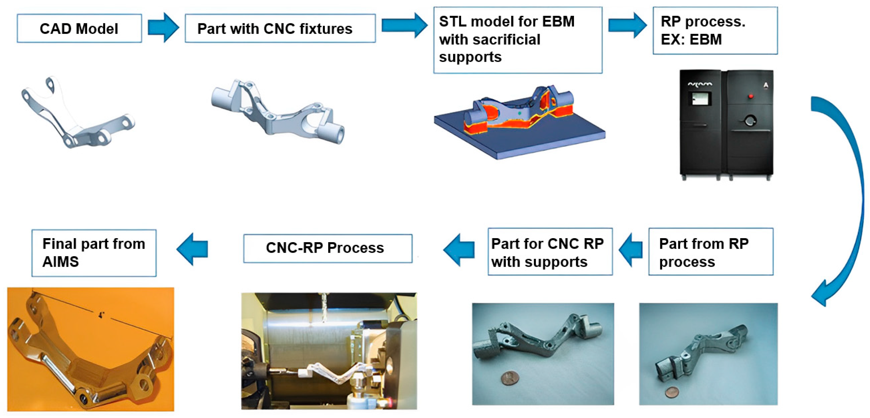
Figure 1. The classification of additive manufacturing technologies [5,9].
Applsci 13 08383 g001
Figure 2. The classification of additive manufacturing technologies. Reprinted with permission from [28]. Copyright 2015 Elsevier B.V.
Applsci 13 08383 g002
Figure 3. The classification of additive manufacturing technologies. Reprinted with permission from [29]. Copyright 2016 Elsevier B.V.
Applsci 13 08383 g003
Figure 4. Lack of fusion at the interface due to mismatched inclination angle [37].
Applsci 13 08383 g004
Figure 5. Different zones created by WAAM and SLM. Reprinted with permission from [33]. Copyright 2016 Elsevier B.V.
Applsci 13 08383 g005
Figure 6. EDS analysis of elemental distribution across the interface of MS1–H13 HB. Reprinted with permission from [26]. Copyright 2019 Elsevier B.V.
Applsci 13 08383 g006
Figure 7. Material joining strategies [52].
Applsci 13 08383 g007
Figure 8. (a) Steel and Cu interface observation using FIB; (b,c) zoomed interface. Reprinted with permission from [53]. Copyright 2014 Elsevier Inc.
Applsci 13 08383 g008
Figure 9. Microhardness changes across the MS1–H13 interface. Reprinted with permission from [89]. Copyright 2019 Elsevier B.V.
Applsci 13 08383 g009
Figure 10. Heat treatment profile for MS1–H13 hybrid. AQ: Air Quench [26].
Applsci 13 08383 g010
Figure 11. Microstructure variation between wrought H13 and printed MS1. Reprinted with permission from [26]. Copyright 2019 Elsevier B.V.
Applsci 13 08383 g011
Figure 12. Hardness variation at different conditions. Reprinted with permission from [26]. Copyright 2019 Elsevier B.V.
Applsci 13 08383 g012
Figure 13. Sub-structure sketch of a typical martensite grain. Reprinted with permission from [92]. Copyright 2016 Acta Materialia Inc.
Applsci 13 08383 g013
Figure 14. (a) Precipitate strength contribution of the NiAl and Laves phases and (b) total strength [103]. Copyright 2017 Elsevier B.V.
Applsci 13 08383 g014
Figure 15. Interaction energies of different element combinations. Reprinted with permission from [95]. Copyright 2019 Acta Materialia Inc.
Applsci 13 08383 g015
Figure 16. Clustering of (a) Co, Ni, and Ti, (b) Ni, and Ti, and (c) Co distributions relative to their dispersion in BCC Fe. Reprinted with permission from [95]. Copyright 2019 Acta Materialia Inc.
Applsci 13 08383 g016
Figure 17. Change of hardness with aging time. Reprinted with permission from [84]. Copyright 2021 Elsevier B.V.
Applsci 13 08383 g017
Figure 18. Heat treatment schedule for LPBF-EOS SS CX and PH13-8 wrought alloy [122].
Applsci 13 08383 g018
Table 1. Summary of hybrid solutions.
Hybrid TechniqueFe-Based SystemsOther SystemsReferences
AM + CNC part/CNC as post-processingMaraging steels, tool steels, and SS316L. [25,29]
AM as a repairing techniqueMaraging steels, SS316L, and tool steels.Al6061, Ti-6Al-4V; Ni-super-alloys, and brass.[37,38]
Combined AM processesSS316LTi alloys, resin, polymers (PLA, PET), and ceramics.[37,39,41]
Hybrid machineSS316LInconel, PLA, and ABS.[44,45]
AM process on a conventionally made partMaraging steels [34,46,47]
Table 3. Mechanical properties of additively manufactured 17-4PH.
Process-P (W)V (mm/s)H (J/mm)OrientationE (GPa)σy (MPa)σuts (MPa)Elongation (%)HVN
DED—350
[86]
8.336.1Absent40 ± 10400 ± 100900 ± 2005 ± 3441
PBF—190
[85]
7870.24LongitudinalAbsent661 ± 241255 ± 316.2 ± 2.5333 ± 2
PBF—195
[82]
8000.24AbsentTransverse570 ± 13944 ± 3550 ± 1Absent
PBF—95
[87]
3500.27LongitudinalAbsent610 ± 101050 ± 2011 ± 0Absent
TransverseAbsent610 ± 10910 ± 103.5 ± 1.5Absent
Conventional processing—N/A
[88]
Wrought, solution annealed and agedN/AN/A199992101813.4430
Note: P = laser power, v = scanning speed, H = linear heat input, E = Young’s modulus, σy = yield strength, and σuts = tensile strength; HVN is the Vickers Hardness Number.
Table 4. Constants for solid solution strengthening [92].
Elementβi (MPa/at)
Ni708
Mn540
Cr622
Al196
Ti2628
Mo2368
Table 5. Change of mechanical properties with heat treatment [93].
Sample TreatmentYield Strength (MPa)Tensile Strength (MPa)Elongation (%)
As-printed1165 ± 121190 ± 164 ± 1
Aged1660 ± 181980 ± 202 ± 1
Solution-treated1156 ± 121369 ± 1815 ± 1
Disclaimer/Publisher’s Note: The statements, opinions and data contained in all publications are solely those of the individual author(s) and contributor(s) and not of MDPI and/or the editor(s). MDPI and/or the editor(s) disclaim responsibility for any injury to people or property resulting from any ideas, methods, instructions or products referred to in the content.