Abstract
An optimized scheme can improve the navigation accuracy of RINS without changing the inertial devices. In the multi-position stop scheme, the IMU remains stationary for most of the time, which makes motor control easier. However, the installation errors and the scale factor errors of FOG can cause platform misalignment after a certain angle of rotation around the horizontal axis, resulting in a velocity error. Continuous rotation can suppress time-varying errors better, which is of particular importance for FOG, but it can also increase the sawtooth error of the navigation output, and the error in the direction of rotation cannot be offset. To integrate the advantages of both rotation schemes, we propose an improved rotational modulation scheme for tri-axis RINS. In this scheme, the inner gimbal rotates in a two-position and four-order manner, while the middle and outer gimbals rotate continuously in the order of forward-reverse-reverse-forward. Simulation and navigation test results demonstrate that this improved rotational modulation scheme can effectively improve navigation accuracy by 50% and 25% compared with continuous rotation around the azimuth axis and a 16-position scheme with the same inertial devices, which is of great importance for RINS with FOG.
1. Introduction
Inertial navigation is a completely autonomous navigation mode. In the absence of external information input during navigation, the inertial navigation system (INS) can output the complete navigation parameters [1,2,3,4,5]. RINS has a similar frame and rotation axis as the platform inertial navigation system, which can offset the constant and slowly-varying errors of the inertial measurement unit (IMU) and improve the navigation accuracy by about one order of magnitude [6,7,8,9]. RINS also has advantages in initial alignment [10,11] and self-calibration [12,13,14,15,16,17], which have drawn much attention recently [18,19,20,21]. Different kinds of single [22,23,24,25], dual [26,27,28], and tri-axis RINS [18,29,30] can be designed according to actual requirements.
It is important to improve the navigation accuracy of INS by improving system technology instead of choosing more accurate inertial devices. For RINS, the use of a multi-degree of freedom structure can be mainly explained in two aspects: On the one hand, RINS can isolate the angular motion of the external carrier in dynamic navigation by designing various high-precision motor control methods, which can be found in many research articles [18,23,29,30,31].
On the other hand, the optimal design of the rotation scheme can decrease the impact of IMU-related errors on navigation accuracy, and this manuscript mainly focuses on this part. According to different application situations and system structures, various rotation schemes can be designed for RINS. For single-axis RINS, the commonly used rotation schemes include single-axis continuous forward and reverse rotation as well as a four-position stop [25,32,33,34,35,36,37]. Both dual-axis and tri-axis systems have the ability to modulate zero bias error in all three directions. However, dual-axis systems are more common due to their simple structure and lower cost. These systems can use continuous forward and reverse schemes [28,38], as well as various multi-position stop schemes, such as 8-position, 16-position, 32-position, and 64-position [16,18,27,39]. There is limited literature available on the design of tri-axis rotation schemes [40].
Those rotation schemes can be divided into two groups: multi-position stop and continuous rotation. Each of these two rotation schemes has its own characteristics. In a multi-position stop scheme, the IMU remains stationary for a large percentage of time [41] except for the flipping actions, which are less demanding on the system’s electromechanical mechanism. Therefore, at present, the commonly used rotation schemes are multi-position stop schemes [16,32,39,42], but with the continuous improvement of motor control accuracy, continuous rotation schemes are becoming more and more popular due to the ability to modulate the errors of inertial devices [33,38,40].
Most of the rotation modulation schemes mentioned in previous research only make use of a single rotation mode. However, this restriction presents challenges for RINS in effectively suppressing various inertial device errors. Keeping stationary in the symmetric position at the same time can effectively offset the constant error of the IMU in the multi-position stop scheme. However, if the errors vary significantly with time, continuous rotation would be a better and more effective method to suppress the constant or slowly-varying error perpendicular to the rotation axis, which will be explained in more depth in the following sections. Continuous rotation would enlarge the oscillation of the navigation output, and the zero bias error in the direction of rotation cannot be compensated. Additionally, it is important to note that the installation errors and the scale factor errors of FOG can easily result in horizontal misalignment angles when flipping around the horizontal axis in the multi-position stop scheme [43].
To combine the advantages of the above two rotation methods and minimize their weaknesses, we propose an improved rotational modulation scheme based on multi-position stop and continuous rotation for tri-axis RINS and analyze the error characteristics of the improved rotational modulation scheme. The improved rotation modulation scheme employs the continuous forward-reverse-reverse-forward rotation of the middle and outer gimbals to strengthen the modulation effect on temperature error terms and the coupling errors of rotation angular velocity. It also takes advantage of the symmetrical positions of the inner gimbal to eliminate zero-bias errors along the rotation axis. Simulations and experiments prove that the improved rotational modulation scheme can effectively improve the navigation accuracy of tri-axis RINS.
The rest of the manuscript is as follows: Section 2 introduces the structure, coordinate system, and symbol definition of tri-axis RINS and the error propagation equation. The improved rotational modulation scheme is described, and its error characteristics are analyzed in Section 3. Section 4 discusses the simulation and experimental results, and Section 5 provides the conclusions.
2. Introduction of Tri-Axis RINS
2.1. System Configuration
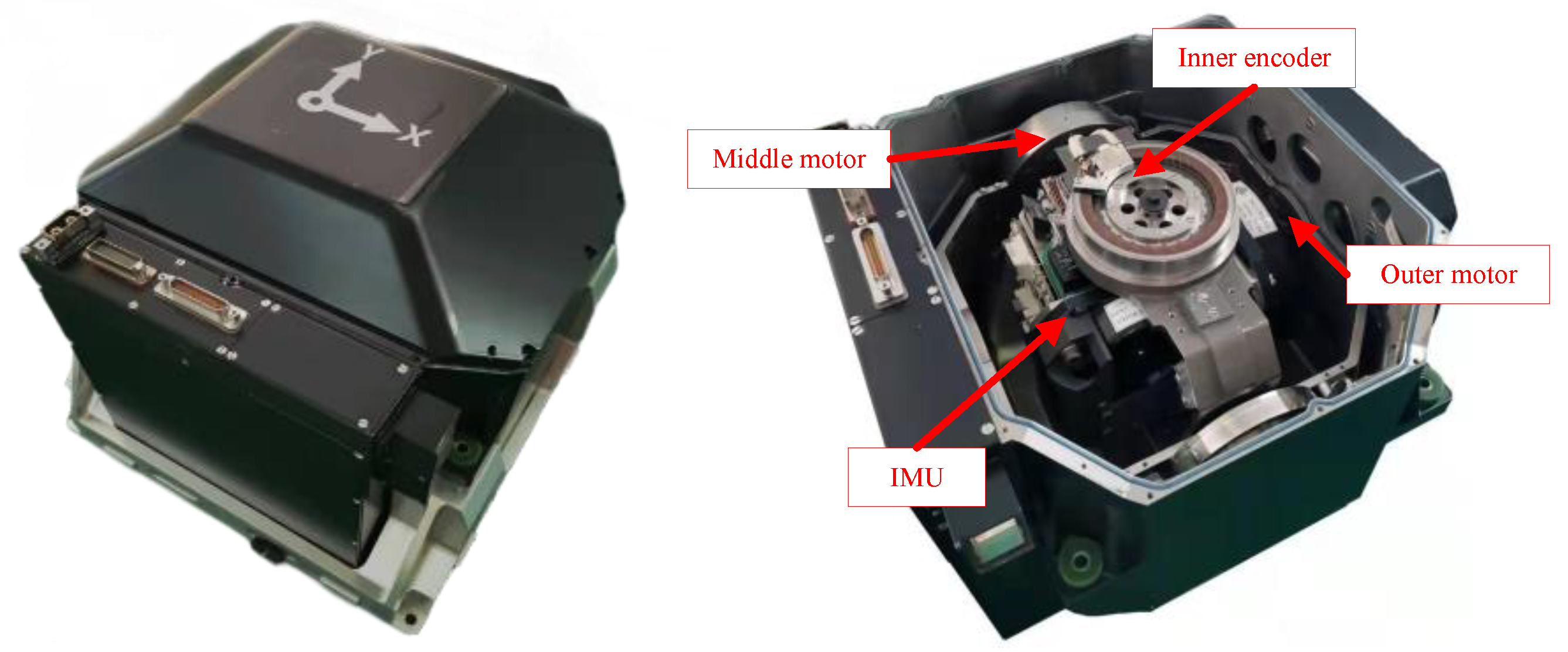
As we can see from Figure 1, there are three orthogonal rotational gimbals inside the tri-axis RINS, which point to the azimuth, pitch, and rolling directions, respectively. On each side of each gimbal, a brushless DC motor and a high-precision angle encoder are installed to drive the gimbal to rotate and collect the rotational angles, denoted as . The combination of three gyros and three accelerometers is called the IMU, surrounded by the rotational gimbals and the relative circuit boards. The gyros and the accelerometers are placed approximately orthogonal to each other. The parameters of the relevant sensors are listed in Table 1. It should be explained that a slightly lower accuracy z-gyro can reduce the size of the tri-axis RINS because the higher the accuracy, the larger the fiber ring radius. The study in this manuscript focuses on the system in Figure 1, but the proposed rotation scheme is available for all types of tri-axis RINS with FOG.
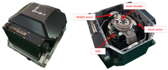
Figure 1.
Structure of Tri-axis RINS.

Table 1.
Parameters of the sensors.
2.2. Definitions of Coordinate Systems and Symbols
For clarity of calculation and expression, we need to define several coordinate systems related to the tri-axis RINS. They are the carrier coordinate frame (noted as b), the navigation coordinate frame representing the local-level geographic coordinate frame (noted as n), the sensor coordinate frame (noted as s), and the gyro installation frame (noted as g). Besides, some symbols also need to be defined; all of these are summarized in Table 2.

Table 2.
Symbol Definitions for Tri-axis RINS.
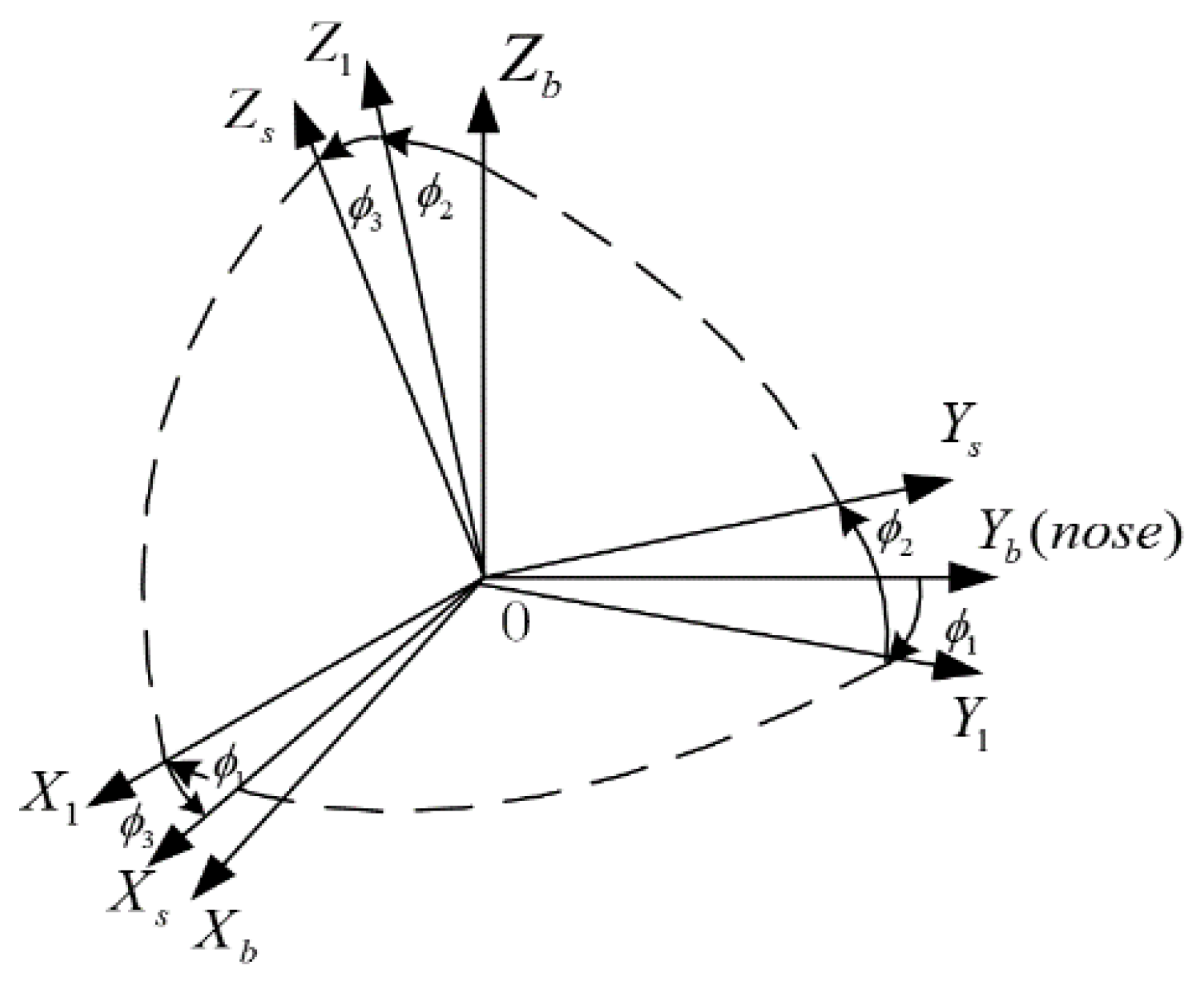
The definition of “s-frame” requires the following clarification: Since the gimbal axis inevitably changes during rotation, we choose the x and y accelerometer measuring axes to determine the plane of the s-frame, which is the projection of the x gyro measurement axis in the plane. is perpendicular to and close to the measurement axis direction of the y-accelerometer , and fits the right-hand rule. After the output angles of the three encoders return to zero, the s-frame and the b-frame overlap. Figure 2 shows the relationship between the s-frame and the b-frame.
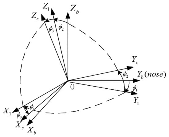
Figure 2.
Relationship between the s-frame and the b-frame.
When the rotational angles of the three gimbals are zero, the inner, middle, and outer gimbals point in the direction respectively. According to the rotation structure of tri-axis RINS, we can define the direction cosine matrix according to Equation (1).
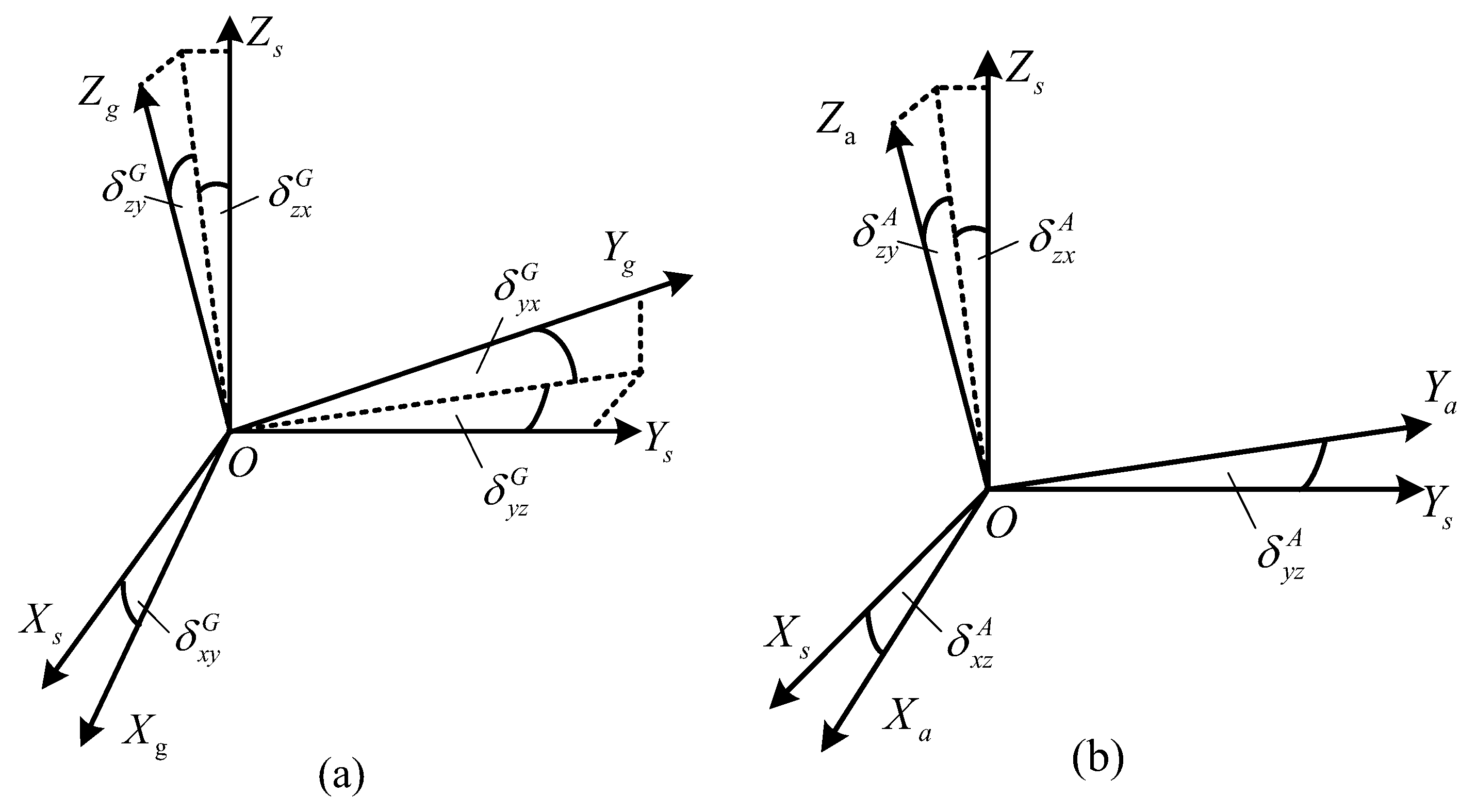
The installation errors of gyros and accelerometers are defined in Figure 3. The g-frame and the a-frame are non-orthogonal coordinate systems consisting of the actual pointing of the gyros and accelerometers, and the transformation matrices from the g-frame and a-frame to the s-frame are shown in Equations (2) and (3). Take as an example to illustrate how installation errors are defined. The superscript represents the gyroscope, and the superscript stands for the non-orthogonal angle between and along . Other definitions will be added to the content accordingly.
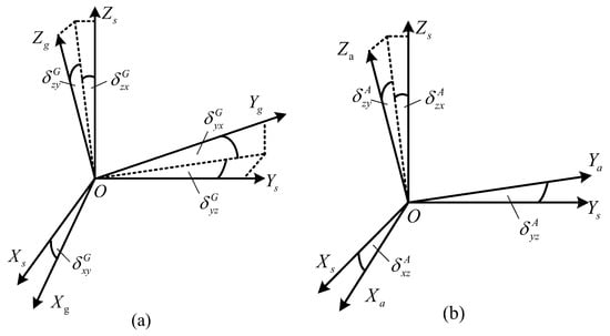
Figure 3.
Definitions of gyros’ and accelerometers’ installation errors. (a) Installation errors of the gyros. (b) Installation errors of the accelerometers.
2.3. Error Propagation Equations of RINS
According to the basic principle of INS, the error propagation equations of INS are shown in Equations (4) and (5). is the misalignment angle of the n-frame and is the differential of . is the velocity of RINS, is the velocity error of RINS, and is the differential of the velocity error. is the angular velocity of the n-frame relative to the Earth and is the error of . is the acceleration of gravity, and is the computational error of the acceleration of gravity.
It is clear to see that the errors of the IMU are introduced into the error equation through and . By integration, the errors in angular velocity and acceleration are converted to attitude and velocity errors, and the velocity errors are again integrated into position errors. The expressions of and are as follows, which is the theoretical basis for the error analysis below.
From the analysis above, when the configuration of the RINS is determined, the key factor affecting the projection of IMU-related errors under the geographic coordinate system is , which is the main reason why studies related to the rotation schemes of the RINS are so popular.
3. Improved Rotational Modulation Scheme Based on Tri-Axis RINS
3.1. Design of Improved Rotational Modulation Scheme
Theoretically, both the multi-position stop scheme and the continuous rotation scheme can completely offset the constant errors of the IMU. Moreover, due to continuous rotation, the gyro will always be sensitive to the rotational angular velocity. Although the errors can be offset by the complete rotation, it still causes a large error oscillation, which is why the multi-position stop scheme is currently more widely used than the continuous rotation scheme.
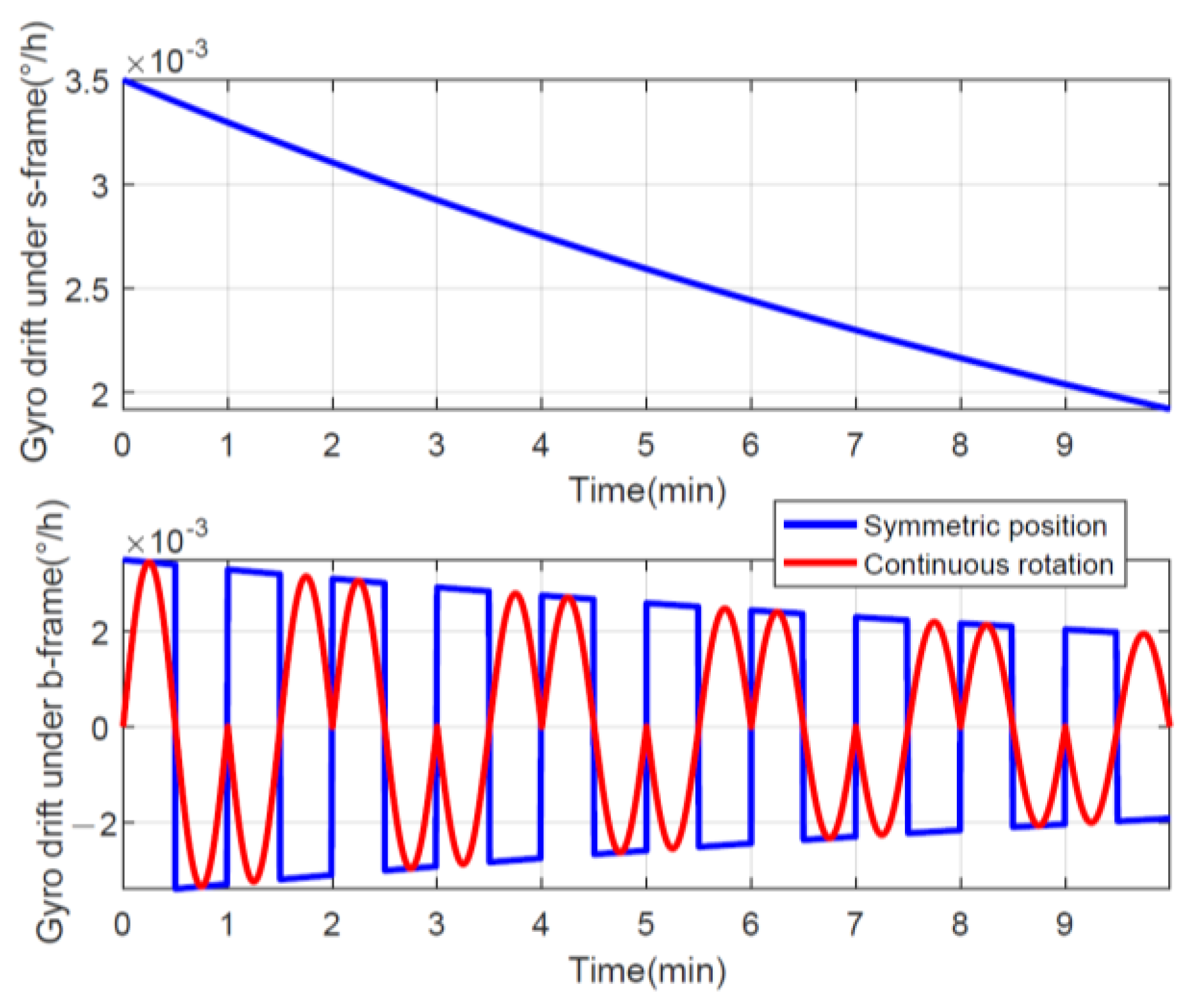
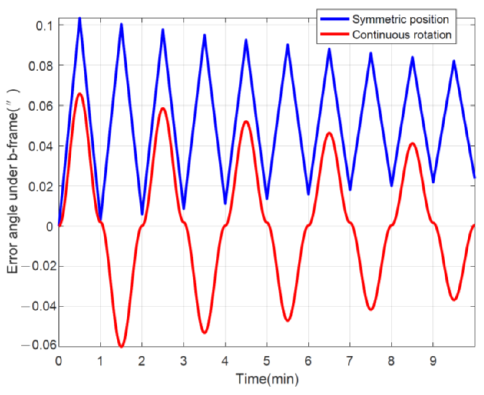
However, the FOG is sensitive to temperature and environment [44,45], and the residual calibration error will change with time, so the modulation effect of the multi-position stop rotation scheme will decrease. As a simple example, it assumes that the gyro drift has a relationship that changes with time as , where °/h. As shown in the top subfigure in Figure 4, the gyro drift under the s-frame changes significantly with time, and we can offset the drift using both a symmetrical position and continuous rotation. Then, without considering other errors, the projection of the drift under the b-frame is the lower subplot in Figure 4, where the time-varying drift becomes a sine wave after continuous rotation, while the symmetric position is a square wave.
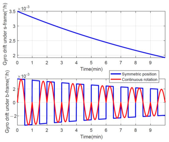
Figure 4.
Gyro drift using different rotation schemes.
After integrating under the b-frame with time, the error angles can be obtained in Figure 5, and it is obvious that the final remaining cumulative error caused by continuous rotation is smaller than the symmetrical position, indicating that the effect of rotation modulation is better. Certainly, shortening the stopping time can further improve the rotational modulation of the symmetric position, but this is essentially approaching continuous rotation as well. In addition, as for the mean value of the error angle, the error oscillation caused by continuous forward and reverse rotation is double-sided, whereas the symmetrical position is one-sided, which has a larger equivalent error.
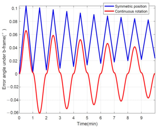
Figure 5.
Error angle using different rotation schemes.
Furthermore, as described in [43], it is worth noting that when the IMU rotates around the horizontal axis by a certain angle, it will excite the influence of scale factor errors and installation errors of the FOG, thus resulting in platform declination, which will be reflected in the velocity error immediately after the rotation. The scale factor error of FOG is poor compared to the laser gyroscope, so the velocity error after flipping the IMU is an observable error, which can even be used as a calibration method.
Accordingly, to fully benefit from these two rotation schemes and the structure of tri-axis RINS with FOG, we planned to design an improved rotational modulation scheme based on multi-position stops and continuous rotation. For an improved rotational modulation scheme of tri-axis RINS, it is essential to design which rotation axis state is multi-position stop and which axis state is continuous rotation. From the analysis in [43], it can be seen that, for INS with FOG, the rotation around the horizontal axis is more suitable to complete a complete rotation than a certain angle rotation. When the system rotates around the azimuth axis, the platform deflection caused by the azimuth deviation projected into the horizontal plane takes some time to accumulate.
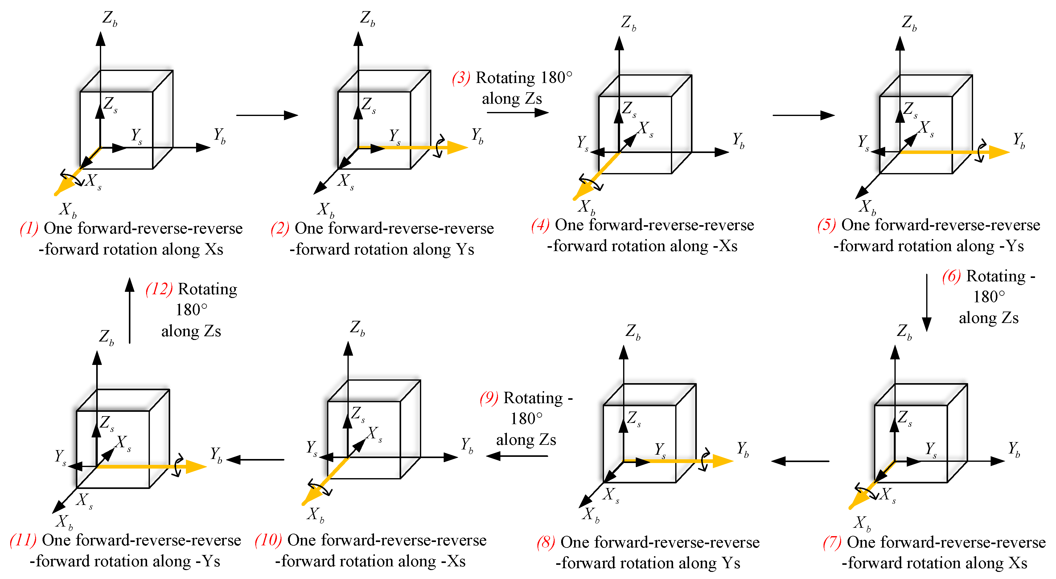
Therefore, we design the improved rotational modulation scheme as follows: the inner gimbal is the multi-position stop, while the middle and outer gimbal are the continuous forward-reverse-reverse-forward rotation. The advantage of such continuous rotation is that not only does it make the error accumulation due to gyro scale factor errors zero, but its average value is also zero.
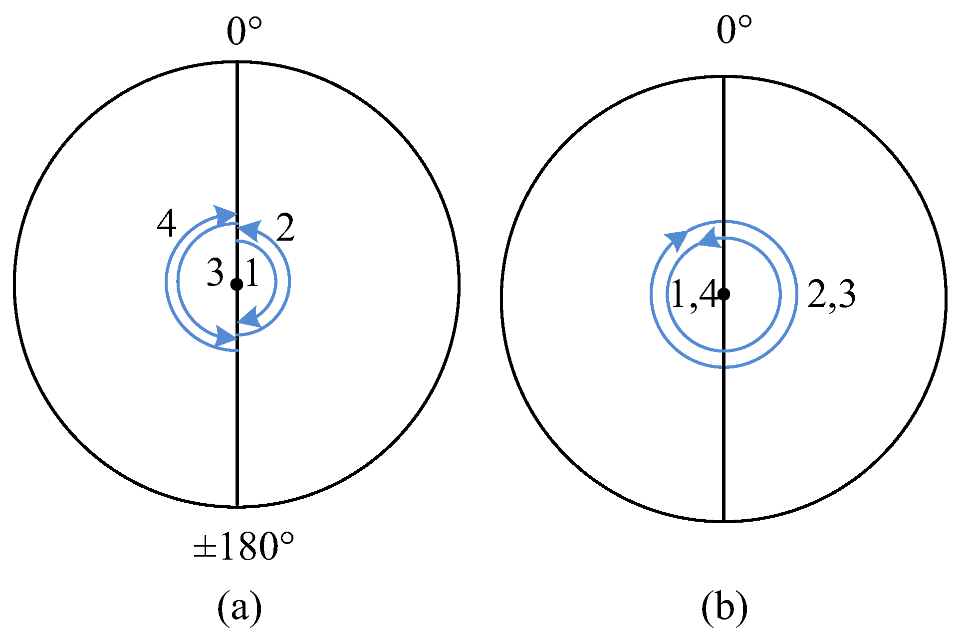
As shown in Figure 6, when the rotational angle of the inner encoder is between 0° and 180°, the IMU completes the forward-reverse-reverse-forward rotation around the middle and outer gimbals. To make the mean value of the coupling error between the z-gyro scale factor error and the rotational angle, the transposition order of the inner gimbal is 0°, 180°, 0°, −180°, and the rotation state of the three gimbals is shown in Figure 7. The rotation angle speed is 6°/s to effectively modulate the errors perpendicular to the rotational axis and dual-axis RINS cannot accomplish the improved rotational modulation scheme.
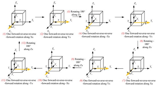
Figure 6.
The whole process of the improved rotational modulation scheme.
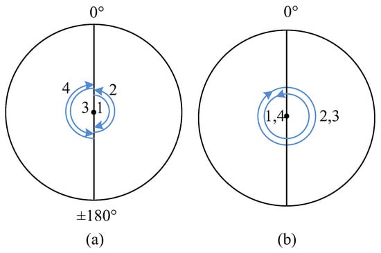
Figure 7.
Rotation state of three gimbals in the improved rotational modulation scheme. (a) Rotation state of the inner gimbal. (b) Rotation state of the middle and outer gimbals.
3.2. Error Characteristics of Different Rotation Schemes
To evaluate the effectiveness of the improved rotational modulation scheme in reducing various inertial device errors, we will compare it with other commonly used schemes in RINS. By comparing the error characteristics of different rotational schemes, specifically focusing on zero bias error, scale factor error, and device installation error, we can demonstrate the advantages of the improved rotational modulation scheme.
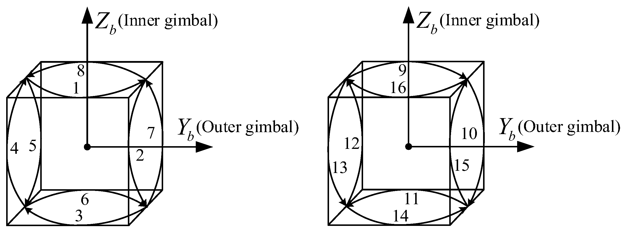
We denote continuous forward and reverse rotation around the azimuth axis as Scheme A, the conventional 16-position stop as Scheme B, and the improved rotational modulation scheme proposed in this manuscript as Scheme C. To facilitate the analysis, the rotation angular velocity of all schemes in this manuscript is set to and the stopping time at each position of Scheme B is . When the angular velocity of rotation is , the time to complete a 360° rotation is . The periods of the three schemes are , and . A simple diagram of the 16-position stop scheme is shown in Figure 8.
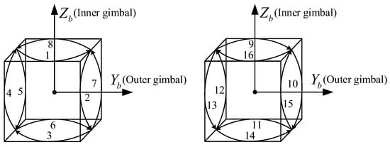
Figure 8.
The diagram of the 16-position stop scheme.
After getting and , we can analyze the gyro-related and accelerometer-related errors using the same analysis method. Hence, the manuscript focuses on the relevant errors of the FOG, and the analysis of accelerometer-related errors will not be expanded here. Besides, the relationship between time-varying errors and navigation accuracy is complicated, so the following analysis is aimed at constant errors, which is convenient for comparing the characteristics of different rotation schemes.
The zero-bias error has a significant impact on the accuracy of navigation over time and is considered one of the most influential errors. The principle of inertial navigation error shows that the equivalent northward drift and the equivalent upward drift of INS in the geographic coordinate system will cause cumulative errors in longitude.
The polar axis drift is composed of and the specific expression is . For RINS, is the residual gyro drift after rotating modulation, which is also determined by the rotation scheme. We can compare the navigation accuracy of different rotation schemes by calculating the polar axis drift.
In Scheme B, the effect of constant gyroscope drift can be canceled out by using symmetrical stop positions, which do not produce equivalent drift. In a complete period of scheme C, the drift of the z-gyro is not modulated when rotating through the inner frame. In addition, the unmodulated drift of x-gyro and y-gyro could be completely canceled because the x and y gyro point exactly oppositely when the angles of the inner encoder are 0° and 180°, respectively. Then, the equivalent polar axis drifts of Schemes A, B, and C are as follows:
From Equation (9), it can be found that Scheme B has almost no equivalent constant polar axis gyro drift, and the polar axis drift of Scheme A is 17 times higher than that of Scheme C. For the RINS studied in this manuscript, the polar axis drift can be reduced to less than 0.0002 by using Scheme C. This indicates that using both Scheme B and Scheme C can significantly reduce the positioning error of the tri-axis RINS and improve navigation accuracy over time. It should be emphasized that the variation of IMU-related errors with time and temperature is not considered in the current analysis because it is difficult to calculate quantitatively, which happens to be the significant physical characteristic of FOG. As a result, the actual modulation effect of Scheme C is better than the theoretical analysis and is well suited for tri-axis RINS with FOG.
In addition to the drift of the gyroscope, various errors, such as scale factor errors and installation errors, can affect the accuracy of navigation. The rotational angular velocity is much larger than the earth’s rotational angular velocity so we mainly analyze the coupling error of the scale factor errors and installation errors with . For the simplicity of the analysis, it is assumed that the RINS is stationary and the direction cosine matrix from the b-system to the n-system is . For scheme A, the angles of the middle and outer encoders are zero, and we set the rotation angle speed of the inner gimbal to be the same as scheme C for comparison purposes, so the true angular velocity under the s-frame is and the coupling error is:
Therefore, the error angle in the n-frame is and the error angles after forward rotation of 360° and reverse rotation of 360° are and . Using a similar method, we can also obtain the error angles of Schemes B and C in the n-frame and then list them in Table 3 and Table 4. The average values of the three rotation schemes are , and such oscillation errors can cause equivalent drift. Although the equivalent drift will gradually decrease with time, it is still harmful to navigation accuracy, especially in the early stages of navigation.

Table 3.
Error Angles in the n-frame of Scheme B.

Table 4.
Error Angles in the n-frame of Scheme C.
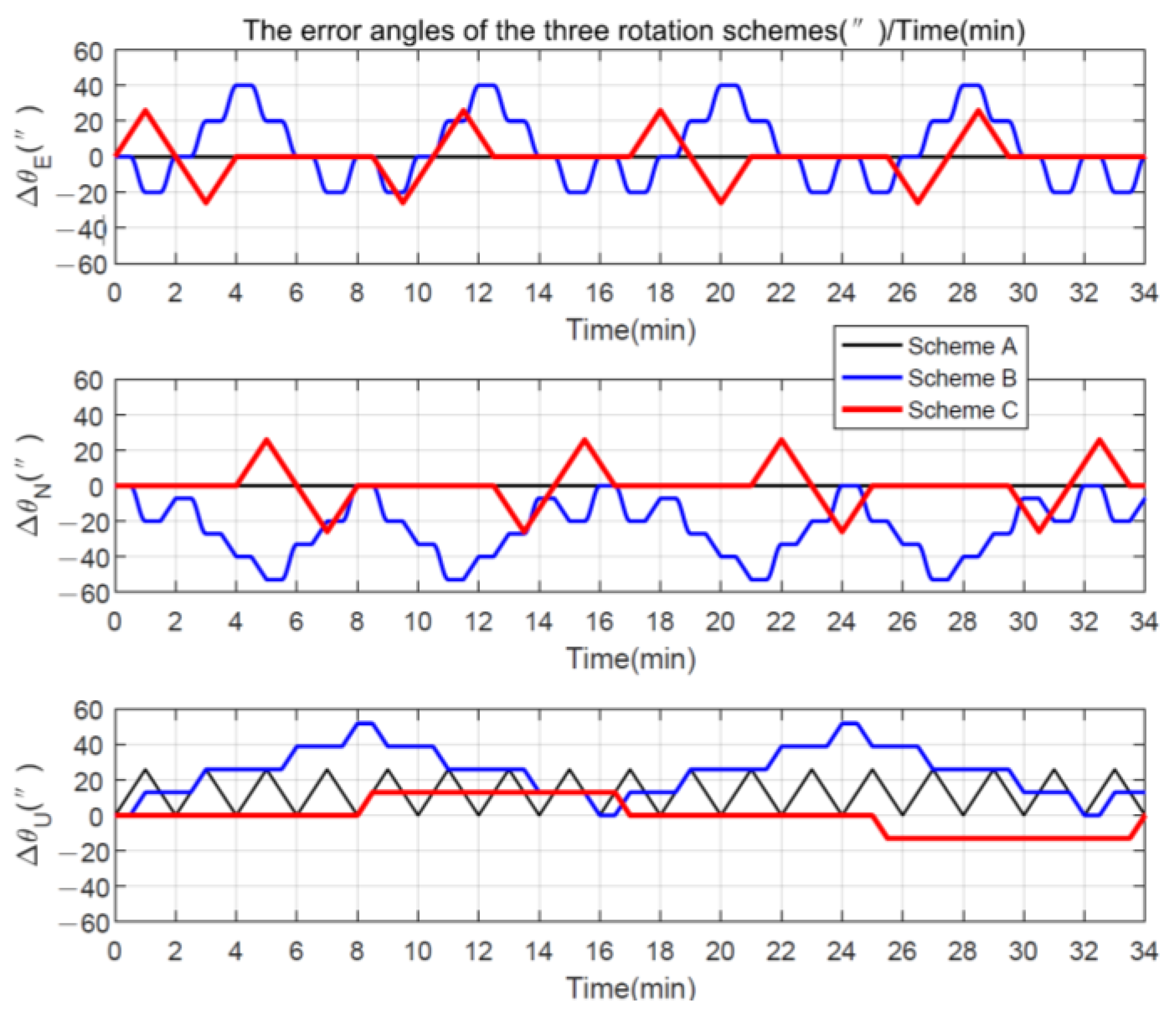
To be more visual, a simple numerical calculation is made below. We assume that the gyro scale factor error is 20 ppm and the installation error is 10″. Then, when , the error angles caused by the scale factor errors and the installation errors of FOG in the geographic system are plotted in Figure 9, and the average values of the three rotation schemes are , and . For example, for a 12-h navigation test, 25.92″ corresponds to a drift of about and such an error would cover the advantage of Scheme B, especially for RINS with FOG.
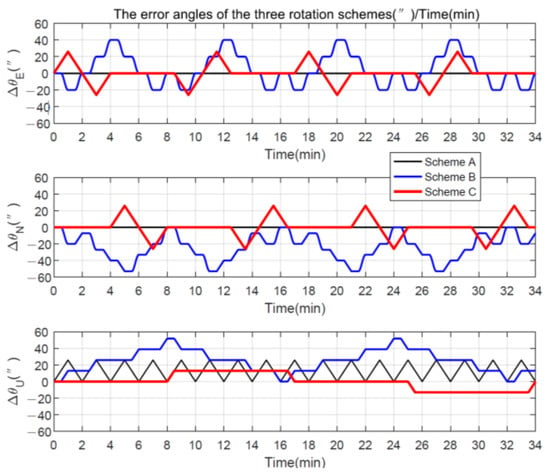
Figure 9.
The error angles of the three rotation schemes.
The smallest average value of the error angle of Scheme C caused by the gyroscope scale factor errors and the installation errors also means that a high demand for calibration accuracy is not required, which is one of the advantages of the improved rotational modulation scheme presented in this manuscript.
Although Scheme C does not completely suppress gyro drifts like Scheme B, it is better at suppressing oscillatory errors caused by gyroscope scale factor errors and installation errors, which is very essential for FOG. Scheme C, proposed in this manuscript, is considered one of the best rotational modulation schemes for improving navigation performance. Such an advantage will be more evident for shorter navigation times, and simulations and experiments based on the actual specifications of the inertial devices can be designed to further illustrate the advantages of the new rotation scheme.
It is important to note that the quantitative effects of each error cannot be accurately known, so the above analysis of the rotational modulation scheme proposed in this manuscript actually serves as a sensitivity analysis. According to Table 5, for Scheme A, the most important error source is the zero-bias error. For Scheme B, the gyro scale factor error and installation error have a significant influence. However, Scheme C is able to comprehensively suppress the influence of these three kinds of errors, making it the best choice for overall navigation performance among the three schemes.

Table 5.
Comparison of error modulation effect of different schemes.
Additionally, the length of navigation time noted as , and the changes in device error values with the environment are important factors of uncertainty. Generally, a gyroscope with a smaller zero bias error will have a smaller temperature error term and a more stable scale factor. However, when comparing FOG and laser gyro with the same zero bias stability, FOG’s scale factor and installation error temperature terms are more evident than those of laser gyro. In such cases, the advantage of Scheme C becomes more significant for RINS using FOG. It is worth noting that Scheme C does not completely eliminate the effect of z-gyro zero bias error, so it is not recommended for use in navigation applications with excessively long navigation times.
4. Simulations and Experiments on Tri-Axis RINS
4.1. Simulations
The error parameters are set in Table 6, designed based on the actual values of inertial devices’ performance parameters. To better simulate the characteristics of INS with FOG, 10% of the actual calibration result of the temperature coefficient of each error is taken as the remaining error of calibration. Due to the large number of temperature error coefficients and different temperature models, the numerical value of each temperature coefficient is not shown in the manuscript. The initial location is 116 E, 40 N, and the b-frame coincides with the n-frame. The schematic diagram of the simulation is shown in Figure 10, and the navigation results were obtained by completing a 12-h static navigation simulation using Schemes A, B, and C.

Table 6.
Error Parameters Setting Of Simulations.

Figure 10.
The navigation simulation flowchart.
The eastward and northward position errors for the static navigation tests are defined in Equations (11) and (12). represent the initial latitude and longitude of RINS and represent the radius of the Earth.
Additionally, to evaluate the navigation accuracy uniformly for different time lengths, the calculation process of the Circular Error Probability (CEP) is shown in Equations (13) and (14):
where is the navigation time sequence, which is a sequence of 1 s intervals in this manuscript? is the radial position error at the moment of and n represents the number of sampling points throughout the navigation process.
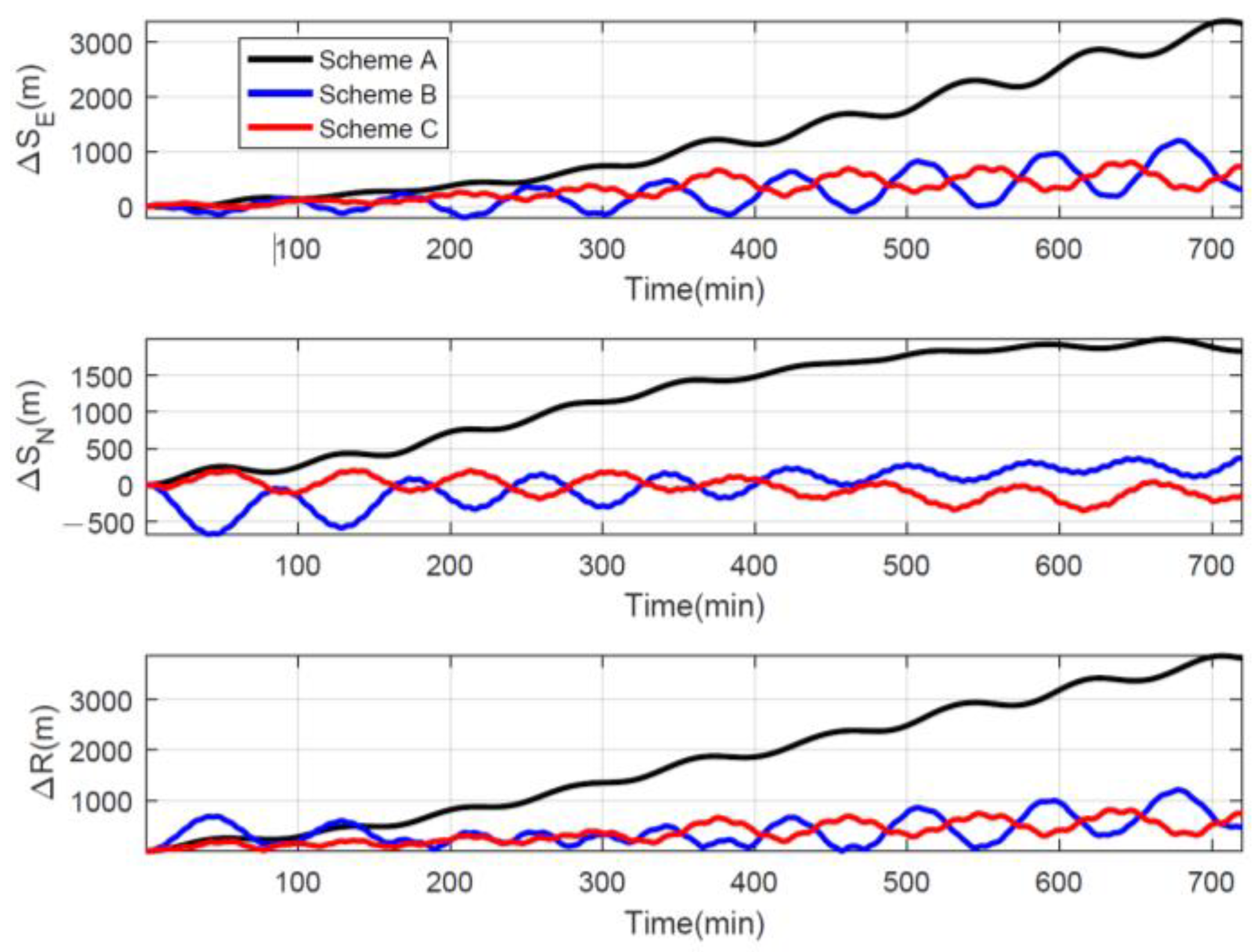
As shown in Figure 11, the position error of Schemes B and C is significantly smaller than that of Scheme A. The CEPs of the three rotation schemes are respectively 0.129 n mile/h, 0.084 n mile/h, and 0.034 n mile/h, and the CEP of Scheme C is the smallest. The maximum radial position errors within the 6-h navigation of the three rotation schemes are 1835.4 m, 687.1 m, and 536.1 m, which also shows the advantage of Scheme C. Therefore, the improved rotational modulation scheme is a good choice for tri-axis RINS with FOG, especially when the navigation time is short because the effect of z-gyro drift is not so evident.
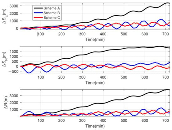
Figure 11.
Position errors of different rotation schemes.
4.2. Experiments and Discussion
In the dynamic environment, the carrier angular and line motions are coupled with IMU-related errors to excite new navigation errors, which are not only caused by the rotation scheme but are also associated with the calibration accuracy and control method of the RINS. At present, the same static navigation experiments using Schemes A, B, and C are sufficient to prove the advantages of the improved rotational modulation scheme proposed in this manuscript.
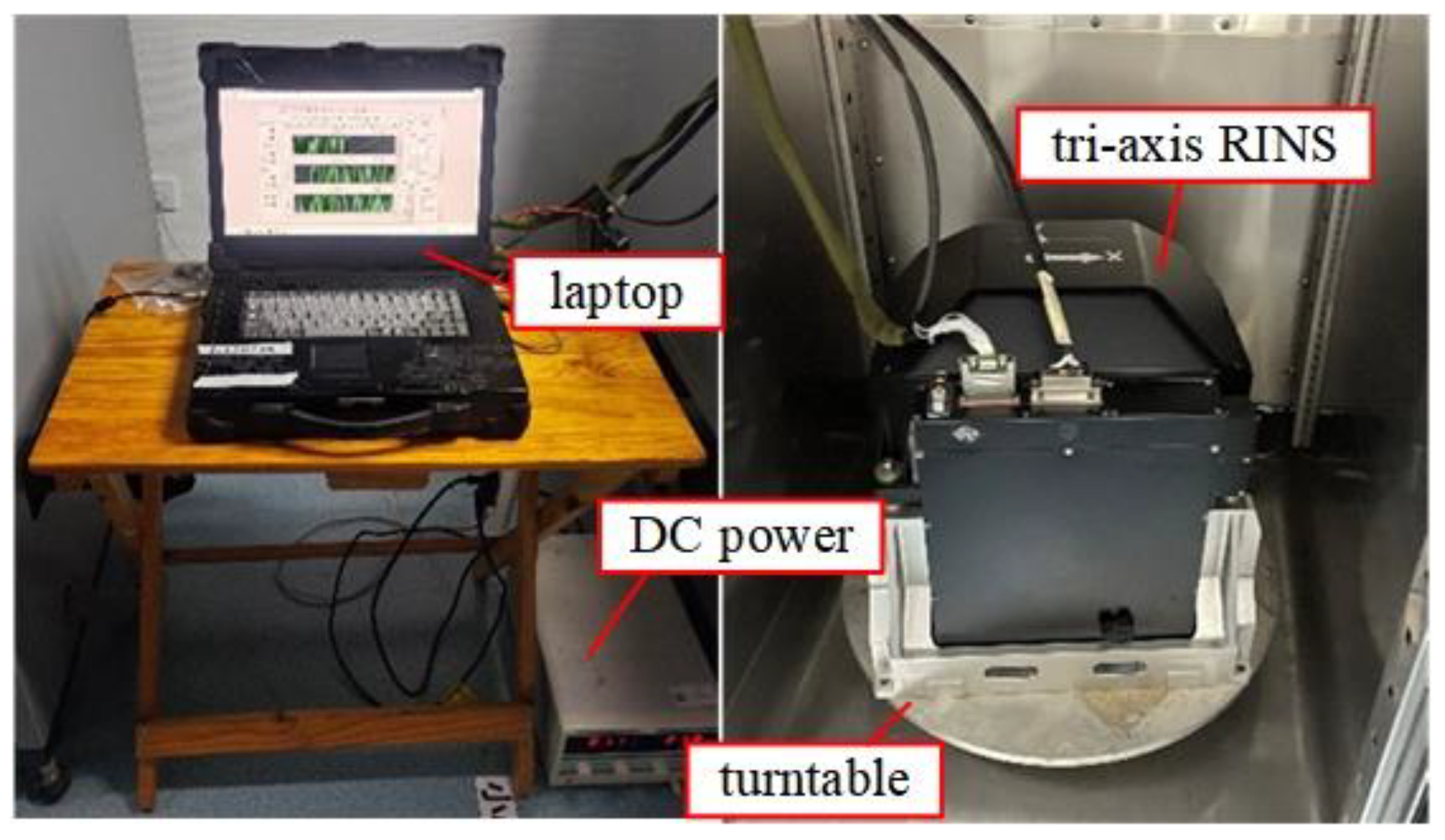
As shown in Figure 12, the tri-axis RINS was fixed on a single-axis speed turntable, and a DC voltage regulator supplied the power. The laptop recorded the original data from the IMU and drew the 1 Hz navigation data on the screen. The design of different rotation schemes requires determining the command angles for the three motors. In our current test environment, which is mainly static, we use the high-precision encoder output as feedback for motor control instructions. However, when the structure of the tri-axis RINS changes or the carrier is in a dynamic environment, we need to reallocate the motor control command angles. Our ultimate goal is to achieve the rotational modulation scheme of the IMU in the geographic coordinate system.
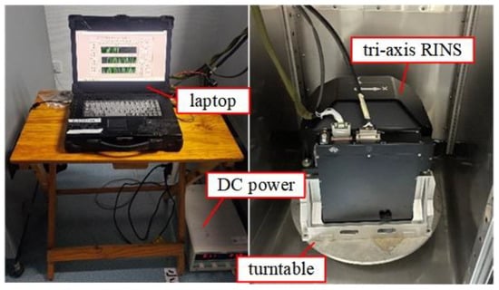
Figure 12.
Experimental environment.
Since this manuscript mainly demonstrates the advantages of the improved rotational modulation scheme, there is no strict requirement on the initial attitudes and heading angle of RINS, and it is enough to ensure that the turntable is locked during the static navigation experiments. The model of initial alignment and the rotation scheme during alignment were the same, so we mainly focused on the effect of the rotation schemes on navigation accuracy. The navigation time of each test is more than 6 h because more than 1/4 of the Earth’s cycle is convenient to observe the error pattern.
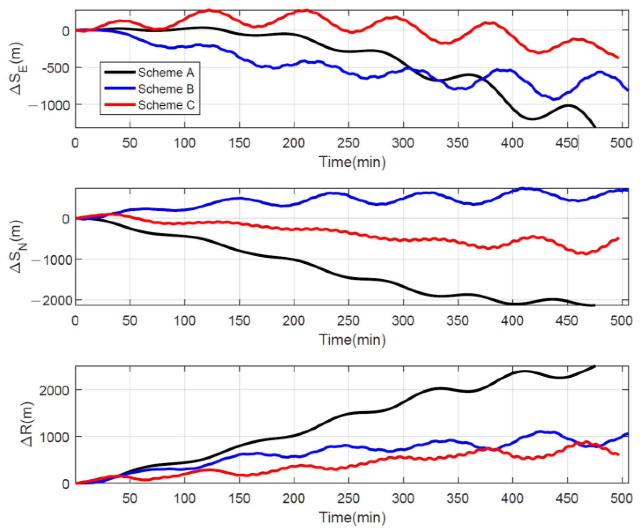
Under the same initial alignment conditions and navigation environment, we obtained the following navigation results: The position errors of the three schemes for a certain navigation test were plotted in Figure 13, and it is obvious that Scheme C has the smallest position error.
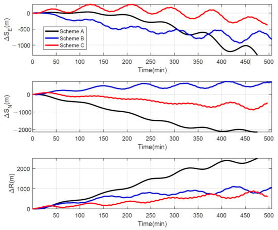
Figure 13.
Navigation test position errors for three rotation schemes.
The CEP was calculated to compare the navigation performance of different rotation schemes. The CEPs for all tests are tabulated in Table 7, and the mean values of the three schemes are 0.109 n mile/h, 0.070 n mile/h, and 0.053 n mile/h, respectively. By using Scheme C, we can significantly improve navigation performance compared to Schemes A and B, with improvements of 51% and 25%, respectively. To compare the navigation results from multiple perspectives, we also list the maximum radial position errors for each group of navigation experiments within 6 h in Table 8 and it is evident that the average value of the maximum radial position error of Scheme C is less than half of the other two schemes.

Table 7.
Circular Error Probability of the three schemes.

Table 8.
Maximum radial position errors during 6 h navigation of the three schemes.
In conclusion, it is quite visible from the results of simulations and actual navigation tests that the improved rotational modulation scheme can effectively reduce navigation errors despite the poor temperature stability of FOG.
5. Conclusions
This manuscript presented an improved rotational modulation scheme based on a multi-position stop and continuous rotation based on tri-axis RINS with FOG. Due to the low-temperature stability and large-scale factor error of the FOG, we designed an improved rotational modulation scheme that can improve navigation accuracy by combining the continuous rotation of the middle and outer gimbals with the two-position transposition of the inner gimbal. The design idea and error modulation principles were also analyzed.
The highlight of this manuscript is that the improved rotational modulation scheme fully combines the advantages of multi-position stop and continuous rotation to suppress the influence of FOG scale factor errors and installation errors on the basis of relatively good suppression of zero bias errors, thus achieving better navigation accuracy. The improved rotational modulation scheme gives full play to the structural characteristics of the tri-axis RINS to improve navigation performance, which has important research significance and engineering value for the research of RINS with FOG.
The proposed scheme can be applied without relying on the accuracy of the gyros, making it suitable for reducing system costs in high-precision navigation environments like ships. However, implementing this scheme in RINS with fewer rotating axes poses challenges. Furthermore, the authors need to explore motor control methods and adjust the system structure to prevent the dynamic environment from affecting the modulation effect. This aspect also requires further in-depth research in the future.
Author Contributions
Conceptualization, W.W. and Y.L. (Yao Lu); methodology, W.W. and Y.L. (Yao Lu); software, Y.L. (Yao Lu); validation, Y.L. (Yao Lu), Y.L. (Yuao Liu) and Z.G.; formal analysis, Y.L. (Yao Lu); investigation, W.W.; resources, W.W.; data curation, Y.L. (Yao Lu); writing—original draft preparation, Y.L. (Yao Lu); writing—review and editing, W.W. and Y.L. (Yao Lu); visualization, Y.L. (Yao Lu); supervision, W.W.; project administration, W.W. All authors have read and agreed to the published version of the manuscript.
Funding
This research received no external funding.
Institutional Review Board Statement
Not applicable.
Informed Consent Statement
Not applicable.
Data Availability Statement
Data sharing was not applicable to this article.
Conflicts of Interest
The authors declare no conflict of interest.
References
- Titterton, D.; Weston, J. Strapdown Inertial Navigation Technology; Institution of Electrical Engineers: Stevenage, UK, 2004. [Google Scholar]
- Li, J.; Dang, P.; Li, Y.; Gu, B. A General Euler Angle Error Model of Strapdown Inertial Navigation Systems. Appl. Sci. 2018, 8, 74. [Google Scholar] [CrossRef]
- Wu, G.; Fang, X.; Song, Y.; Chen, N.; Liang, M.; Li, J.; Qiao, F. Simulation Optimization and Application of Shearer Strapdown Inertial Navigation System Modulation Scheme. Sensors 2023, 23, 4290. [Google Scholar] [CrossRef] [PubMed]
- Wu, G.; Fang, X.; Song, Y.; Liang, M.; Chen, N. Study on the Shearer Attitude Sensing Error Compensation Method Based on Strapdown Inertial Navigation System. Appl. Sci. 2022, 12, 10848. [Google Scholar] [CrossRef]
- Wu, G.; Fang, X.; Zhang, L.; Liang, M.; Lv, J.; Quan, Z. Positioning Accuracy of the Shearer Based on a Strapdown Inertial Navigation System in Underground Coal Mining. Appl. Sci. 2020, 10, 2176. [Google Scholar] [CrossRef]
- Sun, W.; Gao, Y. Fiber-based rotary strapdown inertial navigation system. Opt. Eng. 2013, 52, 076106. [Google Scholar] [CrossRef]
- Ishibashi, S.; Tsukioka, S.; Yoshida, H.; Hyakudome, T.; Ishikawa, A. Accuracy Improvement of an Inertial Navigation System Brought about by the Rotational Motion. In Proceedings of the OCEANS 2007—Europe, Aberdeen, UK, 18–21 June 2007. [Google Scholar]
- Zhu, T.; Wang, L.; Zou, T.; Peng, G. A Dual-Axis Rotation Scheme for Redundant Rotational Inertial Navigation System. Micromachines 2023, 14, 351. [Google Scholar] [CrossRef] [PubMed]
- Feng, J. A Review of Rotary Modulation Technology Applied to Strapdown Inertial Navigation System. In Proceedings of the 2018 IEEE CSAA Guidance, Navigation and Control Conference (CGNCC), Xiamen, China, 10–12 August 2018; pp. 1–3. [Google Scholar]
- Song, T.; Li, K.; Wang, L.; Sui, J.; Wang, L. A rapid and high-precision initial alignment scheme for dual-axis rotational inertial navigation system. Microsyst. Technol. 2017, 23, 5515–5525. [Google Scholar] [CrossRef]
- Gao, W.; Zhang, Y.; Wang, J. Research on Initial Alignment and Self-Calibration of Rotary Strapdown Inertial Navigation Systems. Sensors 2015, 15, 3154–3171. [Google Scholar] [CrossRef]
- Li, K.; Gao, P.; Wang, L.; Zhang, Q. Analysis and Improvement of Attitude Output Accuracy in Rotation Inertial Navigation System. Math. Probl. Eng. 2015, 2015, 768174. [Google Scholar] [CrossRef]
- Liu, Z.; Wang, L.; Li, K.; Han, H. Analysis and Improvement of Attitude Output Accuracy in Tri-Axis Rotational Inertial Navigation System. IEEE Sens. J. 2020, 20, 6091–6100. [Google Scholar] [CrossRef]
- Gao, P.; Li, K.; Wang, L.; Liu, Z. A self-calibration method for tri-axis rotational inertial navigation system. Meas. Sci. Technol. 2016, 27, 115009. [Google Scholar] [CrossRef]
- Zhou, Y.; Deng, Z.; Wang, B.; Xiao, X.; Wang, M. Analytical Method of the Performance of the Rotational INS based on the Spatial Accumulation of the Inertial Instrument Biases. IFAC Proc. Vol. 2014, 47, 9649–9653. [Google Scholar] [CrossRef]
- Kang, L.; Ye, L.; Song, K.; Zhou, Y. Attitude Heading Reference System Using MEMS Inertial Sensors with Dual-Axis Rotation. Sensors 2014, 14, 18075–18095. [Google Scholar] [CrossRef] [PubMed]
- Song, N.; Cai, Q.; Yang, G.; Yin, H. Analysis and calibration of the mounting errors between inertial measurement unit and turntable in dual-axis rotational inertial navigation system. Meas. Sci. Technol. 2013, 24, 115002. [Google Scholar] [CrossRef]
- Liu, Z.; Wang, L.; Wang, W.; Gao, P. An improved rotation scheme for Tri-axis rotational inertial navigation system. Microsyst. Technol. 2017, 23, 5423–5433. [Google Scholar] [CrossRef]
- Niu, M.; Sun, X.; Ma, H.; Zhu, Z.; Huang, T.; Song, K. Analysis and Design of Wireless Power Transfer System for Rotational Inertial Navigation Application. Appl. Sci. 2022, 12, 6392. [Google Scholar] [CrossRef]
- Yuan, X.; Li, J.; Zhang, X.; Feng, K.; Wei, X.; Zhang, D.; Mi, J. A Low-Cost MEMS Missile-Borne Compound Rotation Modulation Scheme. Sensors 2021, 21, 4910. [Google Scholar] [CrossRef]
- Zhang, Q.; Wang, L.; Liu, Z.; Feng, P. An Accurate Calibration Method Based on Velocity in a Rotational Inertial Navigation System. Sensors 2015, 15, 18443–18458. [Google Scholar] [CrossRef]
- Li, K.; Chen, Y.; Wang, L. Online self-calibration research of single-axis rotational inertial navigation system. Measurement 2018, 129, 633–641. [Google Scholar] [CrossRef]
- Wang, L.; Li, K.; Chen, Y.; Liu, J.; Xu, Y. Single-axis rotation/azimuth-motion insulation inertial navigation control system with FOGs. Opt. Express 2017, 25, 30956. [Google Scholar] [CrossRef]
- Hu, J.; Zhu, Y.; Shi, X. Estimation of azimuth gyro drifts with single-axis rotational SINS. Xi Tong Gong Cheng Yu Dian Zi Ji Shu/Syst. Eng. Electron. 2018, 40, 2334–2339. [Google Scholar] [CrossRef]
- Feng, S.; Wang, Q. Researching on the compensation technology of rotating mechanism error in single-axis rotation strapdown inertial navigation system. In Proceedings of the International Conference on Mechatronics & Automation, Sichuan, China, 5–8 August 2012. [Google Scholar]
- Song, T.; Wang, X.; Liang, W.; Xing, L. Improved motor control method with measurements of fiber optics gyro (FOG) for dual-axis rotational inertial navigation system (RINS). Opt. Express 2018, 26, 13072–13084. [Google Scholar] [CrossRef] [PubMed]
- Wang, G.; Wang, Q.; Sun, Q.; Xia, X. A New Rotary Scheme of the Dual-Axis Rotary Inertial Navigation System. J. Comput. Theor. Nanosci. 2015, 12, 5674–5684. [Google Scholar] [CrossRef]
- Zha, F.; Chang, L.; He, H. Comprehensive Error Compensation for Dual-Axis Rotational Inertial Navigation System. IEEE Sens. J. 2020, 20, 3788–3802. [Google Scholar] [CrossRef]
- Lu, Y.; Wang, L.; Song, T.X.; Wang, W. A High-Precision Motor Control Method for Tracking Wandering Azimuth Coordinate System Based on Tri-Axis Rotational Inertial Navigation System (RINS). IEEE Sens. J. 2021, 21, 27993–28000. [Google Scholar] [CrossRef]
- Gao, P.; Li, K.; Song, T.; Liu, Z. An Accelerometers-Size-Effect Self-Calibration Method for Triaxis Rotational Inertial Navigation System. IEEE Trans. Ind. Electron. 2018, 65, 1655–1664. [Google Scholar] [CrossRef]
- Zhang, C.; Wang, L.; Zhang, J.; Liu, Z. High precision locking control based on fiber optic gyro and photoelectric encoder for rotational inertial navigation system. IEICE Electron. Express 2016, 13, 20160841. [Google Scholar] [CrossRef]
- Giovanni, C.S., Jr.; Levinson, E. Performance of a ring laser strapdown marine gyrocompass. In Proceedings of the ION 37th Annual Meeting Proceedings, Bad Honnef, Germany, 12–15 October 1981; pp. 28–40. [Google Scholar]
- Yang, Y.; Miao, L.J. Fiber-optic strapdown inertial system with sensing cluster continuous rotation. IEEE Trans. Aerosp. Electron. Syst. 2004, 40, 1173–1178. [Google Scholar] [CrossRef]
- Yang, Y.; Miao, L.J.; Shen, J. Method of Improving the Navigation Accuracy of SINS by Continuous Rotation. J. Beijing Inst. Technol. 2005, 14, 45–49. [Google Scholar]
- Jing, Z.; Li, J.; Zhang, X.; Feng, K.; Zheng, T. A novel rotation scheme for MEMS IMU error mitigation based on a missile-borne rotation semi-strapdown inertial navigation system. Sensors 2019, 19, 1683. [Google Scholar] [CrossRef]
- Sun, W.; Wang, D.; Xu, L.; Xu, L. MEMS-based rotary strapdown inertial navigation system. Measurement 2013, 46, 2585–2596. [Google Scholar] [CrossRef]
- Sun, W.; Xu, A.; Che, L.; Gao, Y. Accuracy Improvement of SINS Based on IMU Rotational Motion. IEEE Aerosp. Electron. Syst. Mag. 2012, 27, 4–10. [Google Scholar] [CrossRef]
- Deng, Z.; Mu, S.; Wang, B. Error modulation scheme analysis of dual-axis rotating strap-down inertial navigation system based on FOG. In Proceedings of the 33rd Chinese Control Conference, Nanjing, China, 28–30 July 2014. [Google Scholar]
- Yuan, B.; Liao, D.; Han, S. Error compensation of an optical gyro INS by multi-axis rotation. Meas. Sci. Technol. 2012, 23, 025102. [Google Scholar] [CrossRef]
- Guan, B.F.; Li, S.H.; Fu, Q.W. Research on Rotation Scheme of Hybrid Inertial Navigation System with Three Rotating Axes. In Proceedings of the 2020 27th Saint Petersburg International Conference on Integrated Navigation Systems (ICINS), St Petersburg, Russia, 25–27 May 2020. [Google Scholar]
- Lv, P.; Lai, J.; Liu, J.; Nie, M. The Compensation Effects of Gyros’ Stochastic Errors in a Rotational Inertial Navigation System. J. Navig. 2014, 67, 1069–1088. [Google Scholar] [CrossRef]
- Levinson, E.; Majure, R. Accuracy Enhancement Techniques Applied to the Marine Ring Laser Inertial Navigator (MARLIN). Navigation 1987, 34, 64–86. [Google Scholar] [CrossRef]
- Wang, L.; Wang, W.; Zhang, Q.; Gao, P.Y. Self-calibration method based on navigation in high-precision inertial navigation system with fiber optic gyro. Opt. Eng. 2014, 53, 064103. [Google Scholar] [CrossRef]
- Ban, J.; Wang, L.; Liu, Z.; Zhang, L. Self-calibration method for temperature errors in multi-axis rotational inertial navigation system. Opt. Express 2020, 28, 8909–8923. [Google Scholar] [CrossRef]
- Dzhashitov, V.E.; Pankratov, V.M.; Golikov, A.V.; Nikolaev, S.G.; Kolevatov, A.P.; Plonikov, A.D.; Koffer, K.V. Hierarchical thermal models of FOG-based strapdown inertial navigation system. Gyroscopy Navig. 2015, 6, 156. [Google Scholar] [CrossRef]
Disclaimer/Publisher’s Note: The statements, opinions and data contained in all publications are solely those of the individual author(s) and contributor(s) and not of MDPI and/or the editor(s). MDPI and/or the editor(s) disclaim responsibility for any injury to people or property resulting from any ideas, methods, instructions or products referred to in the content. |
© 2023 by the authors. Licensee MDPI, Basel, Switzerland. This article is an open access article distributed under the terms and conditions of the Creative Commons Attribution (CC BY) license (https://creativecommons.org/licenses/by/4.0/).

