Abstract
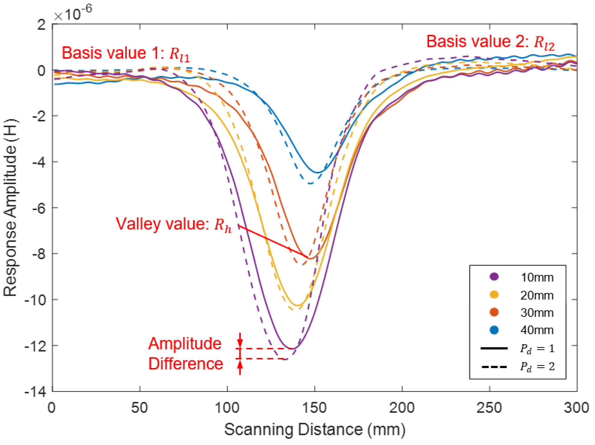
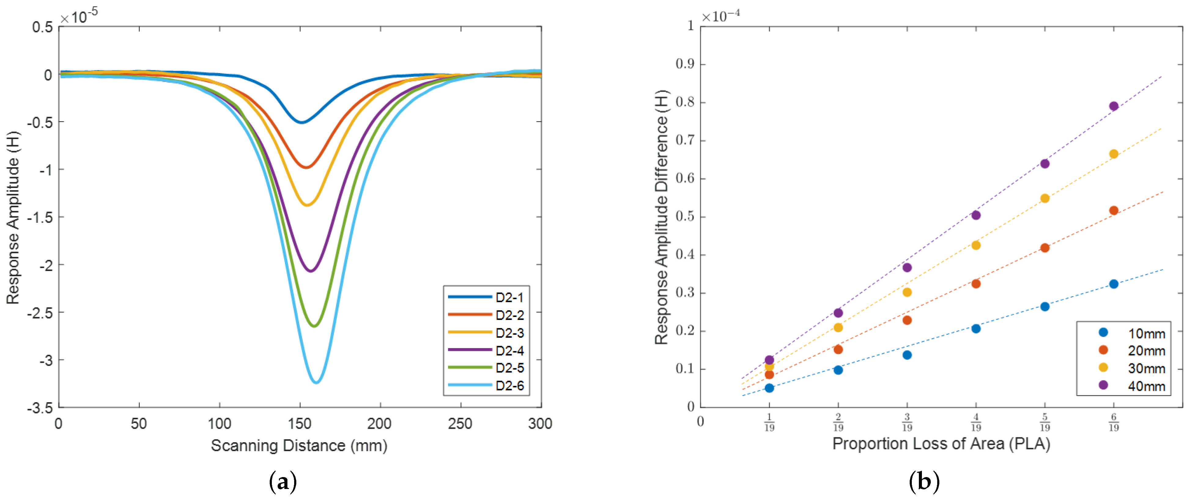
Bridge cables are commonly used in bridge construction, and assessing their condition is crucial for ensuring bridge safety. However, current inspection methods often rely on large and heavy detection mechanical structures, which can be inconvenient during the inspection process. In light of these limitations, this paper proposes a portable non-destructive inspection method for bridge cables that detects the total magnetic flux variations utilizing an inductive search coil sensor. The occurrence of corrosion and cracks in bridge cables leads to changes in their original sectional area and permeability. These changes result in variations in the induced current that is excited by the coil, leading to distortions in both the magnetic field energy and the coil’s self-inductance. Thus, cable damage can be detected inversely by monitoring coil self-inductance variation. To assess the feasibility of this method, a numerical analysis is conducted, and an experimental structure is designed using a mock-up cable specimen with parallel steel wires that have varying degrees of damage. The experimental results demonstrate the effectiveness of the proposed method, which utilizes an inductive search coil sensor, intuitively identifies and quantifies internal flaws on the cable in real-time while maintaining a lightweight structure. The width and amplitude of the coil inductive response show a positive correlation with the flaw’s axial length and cross-sectional area, indicating that these parameters can be utilized to quantify the size of the flaw.
1. Introduction
Cable-stayed bridges are crucial for economic development due to their practical and economical features. The cables play an irreplaceable role in providing loading and bearing capacity in the stay-cable bridge system. Since bridges are important national assets, proper maintenance is necessary to ensure public safety. To maintain a safe service status and avoid accidents and economic losses, structural health monitoring of the system structure is significant [1]. In general, cable damage factors can be divided into two categories: external and internal. External damage factors include corrosion due to sunlight or moisture from damaged wrapping or caulking. Internal damage factors are caused by fatigue due to vibrations, overload, and small corrosion cracks, which can be considered as deterioration arising from external damages.
There are currently two mainstream approaches for detecting the two types of cable damage mentioned above. The first approach is manual flaw detection, which involves visual inspection of cables, splay castings, cable strands, and associated hardware in the anchorages. However, visual testing has limitations for sheathed cables, as damages may occur inside the wrapping, which can make the results subjective and inaccurate. Furthermore, the detecting process involves aerial work with lifting equipment, which increases the risks to workers. The second approach relates to non-destructive testing (NDT) [2,3,4] with sensors, which have been extensively studied for their ability to detect flaws without damaging the material under test. Several studies have been conducted on NDT techniques. Dye Penetrant (DP) testing [5] is a simple and easy method for detecting shallow cracks in steel cable surfaces using liquid dye, which is easily combined with a visual inspection. Manikandan et al. [6] specially analyzed the effects of temperature variations and mechanical vibrations on the performance and accuracy of the liquid penetrant inspection techniques. However, it is costly when assessing quality at multiple locations. Optical Fiber Sensing [7,8] is a stable and precise method. He et al. [9] proposed an approach for monitoring cable force using optical fiber Bragg grating (FBG) sensors and time domain analysis sensing technique. Zhang et al. [10] developed an inclination sensor based on “pendulum-equal strength beam” utilizing Fiber Bragg grating technology to monitor the deflection. But optical fiber sensing is still challenged by issues such as the complexity of the detection process and excessively high sensitivity. Radio-graphic Testing (RT) is a non-destructive testing method that uses either x-rays or gamma rays to examine the internal structure of manufactured components to identify any flaws or defects. Oh et al. [11] used faster R-CNN to realize automated damage detection. However, it should be noted that RT can be costly and may pose health risks due to the potential hazards associated with radiation exposure. Ultrasonic Testing (UT) [12] uses ultrasonic transmission and reception to quickly detect defects with strong penetration ability and defect positioning capacity. Recent studies have proposed various techniques to enhance UT accuracy and efficiency. Zhang et al. [13] utilized a semi-analytical finite element (SAFE) technique to identify guided wave modes for multi-wire bridge cables. Hong et al. [14] employed the matching pursuit algorithm for ultrasonic guided wave detection. Other research efforts have focused on combining UT with other techniques to achieve improved defect visualization, such as the synthetic aperture focusing technique with a remote laser signal and laser-based ultrasonic signal proposed by Selim et al. [15]. Additionally, Wang et al. [16] utilized the ultrasonic coda wave interferometry technique to study the influence of temperature and load on the bridge. However, UT has certain limitations, such as its poor intuitiveness of the detection results. Magnetic particle Testing (MT) [17] detects surface or near-surface flaws in steel structures by analyzing the magnetic flux leakage. It is a method that requires little training for inspectors before practical operation. Tout et al. [18] integrated convolutional neural networks (CNNs) into an automated vision system for magnetic particle inspection. Chen et al. [19] proposed a thermography-based dry MT method that identifies cracks during the magnetic particle testing process. However, MT methods often have shallow depth measurement capabilities, which limits their application scope. Magnetic Flux Leakage (MFL) is a magnetic-based detection technique for cable damage. The MFL technique has been shown to be highly effective in locating flaws by monitoring the variance of magnetic flux leakage [20,21]. Recent studies have introduced novel techniques to enhance the MFL signal denoising algorithm and improve defect identification. Oh et al. [22] introduced kernel principal component analysis to enhance the MFL signal denoising algorithm and identify the defects. Ni et al. [23] used the magnetic flux variation to quantify the defect size. However, despite its effectiveness, the MFL technique suffers from certain limitations, including high sensitivity to the distance between the defect and the sensor, insufficient excitation intensity, and overweight problems. These limitations make it challenging to quantitatively evaluate defects on the cable using MFL. Acoustic Emission (AE) testing [24] is widely used technique for monitoring steel bridge elements, where changes in cable force and vibration frequency during dynamic material processes are monitored. Xin et al. [25] proposed a status-driven acoustic emission monitoring method that combines wavelet analysis and transfer learning through convolutional neural networks. Li et al. [26], on the other hand, presented an AE signal segmentation algorithm that facilitates the extraction of AE signal characteristics by setting segmentation parameters. However, the accuracy of AE detection tends to decrease with increasing distance. In addition, vibration-based methods [27,28] have also been utilized for cable condition assessment by monitoring changes in cable tension. Zarbaf et al. [29] proposed a cable tension estimation framework based on an artificial neural network using parameters such as cable length, mass per unit length, axial stiffness, bending stiffness, cable tension, and corresponding natural frequencies obtained from a comprehensive cable model, enabling accurate estimation of cable tension. Machorro-Lopez et al. [30] used the Shannon entropy index to characterize cable vibration signals and employed a fuzzy logic classifier for pattern recognition to detect and locate cable structural damage affected by environmental vibrations. Peng et al. [31] proposed a long-term condition assessment method for monitoring stay cables based on the concept of the influence surface and the linear relationship between the matching cable tensions of two adjacent cables. Yanez-Borjas et al. [32] introduced a new approach for detecting and locating cable losses using statistical time features (STF) obtained through auto-correlation function (ACF), principal component analysis (PCA), and Mahalanobis distance (MD). Ren et al. [33] developed a Damaged Cable Identification Machine (DCIM) and a Damage Severity Identification Machine (DSIM) based on support vector classification to determine cable damage and its severity.
While the aforementioned methods offer comprehensive solutions for cable flaw-detection, they often involve complex operations, ponderous detection structures and relative non-intuitive representation of detection results. In this paper, a portable non-destructive inspection method for bridge cables is proposed, by leveraging the self-induction phenomenon. The feature of this method lies in its use of a single self-induction coil, which is different from conventional coil-detection configurations that typically rely on separate exciter and receiver coils. This design choice not only reduces data processing requirements but also facilitates a lightweight structure that can be easily carried by robots. During the inspection process, the cable under examination is guided through the self-induction coil. Defects in the cable induce cross-sectional loss, leading to changes in the self-inductance of the coil. Real-time identification and quantification of internal flaws on the cable are achieved by continuously monitoring the self-inductance variation during the scanning process using a search coil sensor. Furthermore, the adoption of a single self-induction coil not only ensures a portable and lightweight system but also simplifies the overall cable flaw detection process. The elimination of separate exciter and receiver coils streamlines the method reduces complexity to a certain extent, which enhances the practicality of the method.
2. Methodology
2.1. Model-Based Principle
Using the basic governing equations, the self-inductance L (H) of a coil driven by an excitation current I (A) can be described as [34]:
where (J) represents the intrinsic magnetic energy of the coil. The magnetic energy is the work done by the power source on the entire current loop during the establishment of the magnetic field [35], which can be expressed using the Maxwell equations as follows:
where B and H represent the induction and the intensity of the magnetic field respectively, and denotes the permeability. Specially, represents the energy density of the magnetic field, which denotes the magnetic field stored per unit volume, with the unit of J/m. Accordingly, the magnetic energy of each element in the Finite Element Model (FEM) could be indicated by the following:
Accordingly, the self-inductance L of the coil is presented:
where A denotes the magnetic vector potential, M refers to the number of the FEM elements, and represents a sub-region corresponding to an element in space. The aforementioned equations demonstrate that, in addition to the factors of excitation current and permeability, the self-inductance of the coil is influenced by the variation of the magnetic vector potential A. In the finite element model, the magnetic vector potential A can be solved under the constraint of , by using the governing equation extended from Maxwell equations:
where J (A) represents the excitation current. Based on the theory of the above partial differential equations and boundary conditions, the magnetic potential A is solvable in COMSOL. Accordingly, the coil inductance can be simulated.
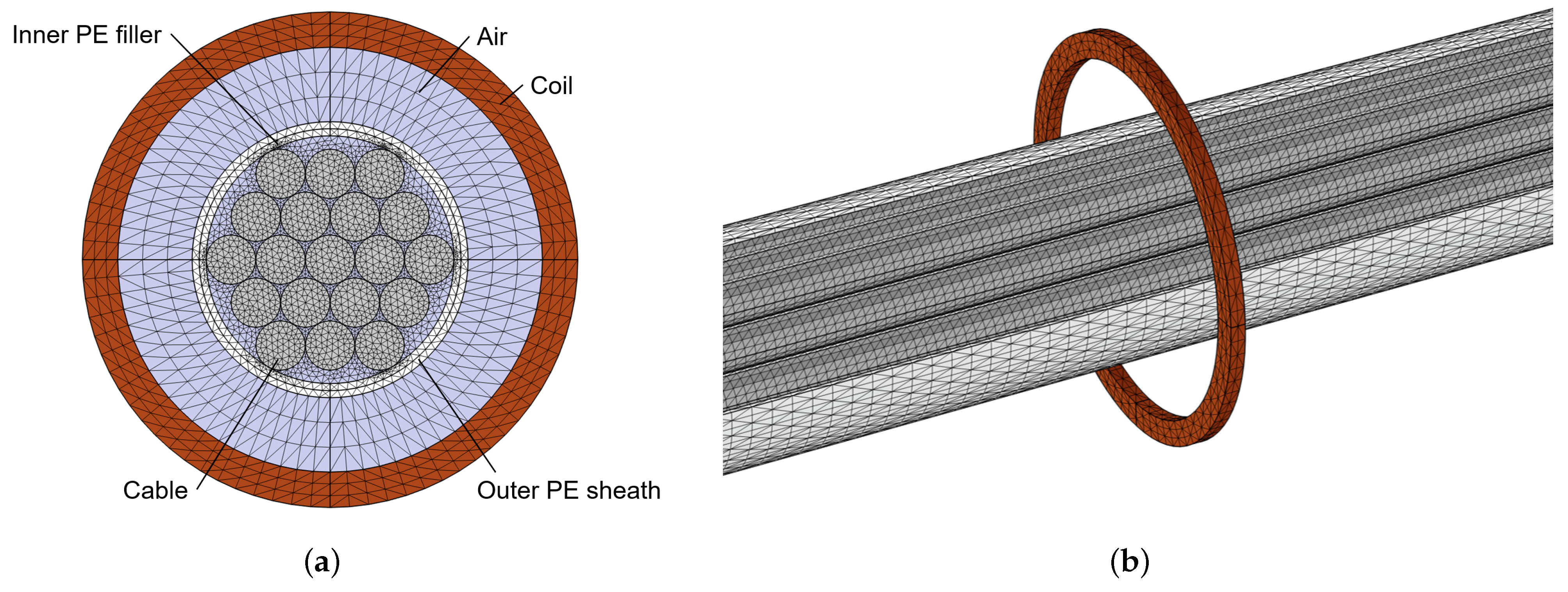
For the purpose of verifying the feasibility and correctness of the proposed approach, a 3-dimensional numerical simulation has been developed to analyze the variation of coil self-inductance along the axial direction of a cable with parallel wires. The effects of the flaw axial length and cross-sectional area were evaluated respectively. This simulation utilizes COMSOL Multiphysics with the AD/DC module and frequency domain analysis. The simulated three-dimensional finite element model (FEM) based on COMSOL is illustrated in Figure 1, including a three-layer cable, polyethylene (PE) sheaths and a coil.
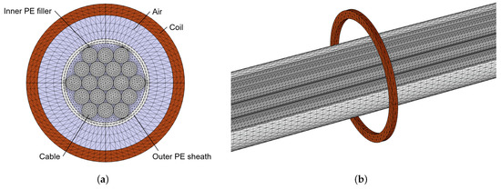
Figure 1.
Finite element mesh division diagram: (a) Cross-sectional mesh diagram; (b) Three-dimensional mesh diagram.
The self-inductance coil features an inner diameter of 60 mm and an outer diameter of 70 mm. It is wound 300 times and excited by a 1 V AC signal at 1000 Hz. The axial scanning length of the coil along the cable is set as 150 mm. The cable’s inner material property is set as “steel”, with a relative permeability of . A 1 mm PE sheath surrounds the cable, with a relative permeability of . The material property of the remaining domain inside the PE sheath is also set as “PE”. The flaws are separately modeled in the middle of the cable, consisting of multiple wire segments. Each segment is considered as one unit flaw, which can be substituted with air having a relative permeability of . To quantify the influence of the flaws on the inductance variation, the proportion loss of area (PLA) is utilized to express the cross-sectional area of the flaw, with each wire representing the smallest unit. Specifically, the position of the flaw is denoted by , where indicates that the flaw is on the innermost layer of the cable.
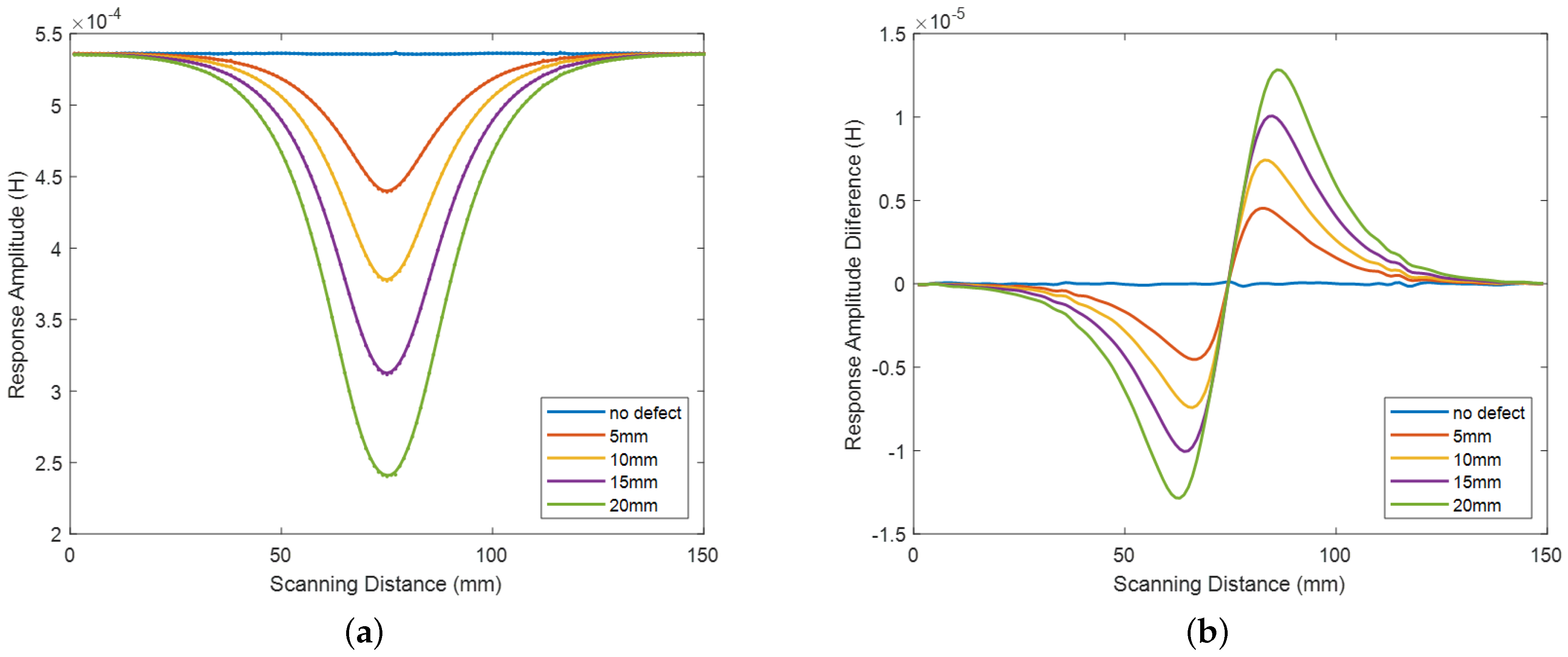
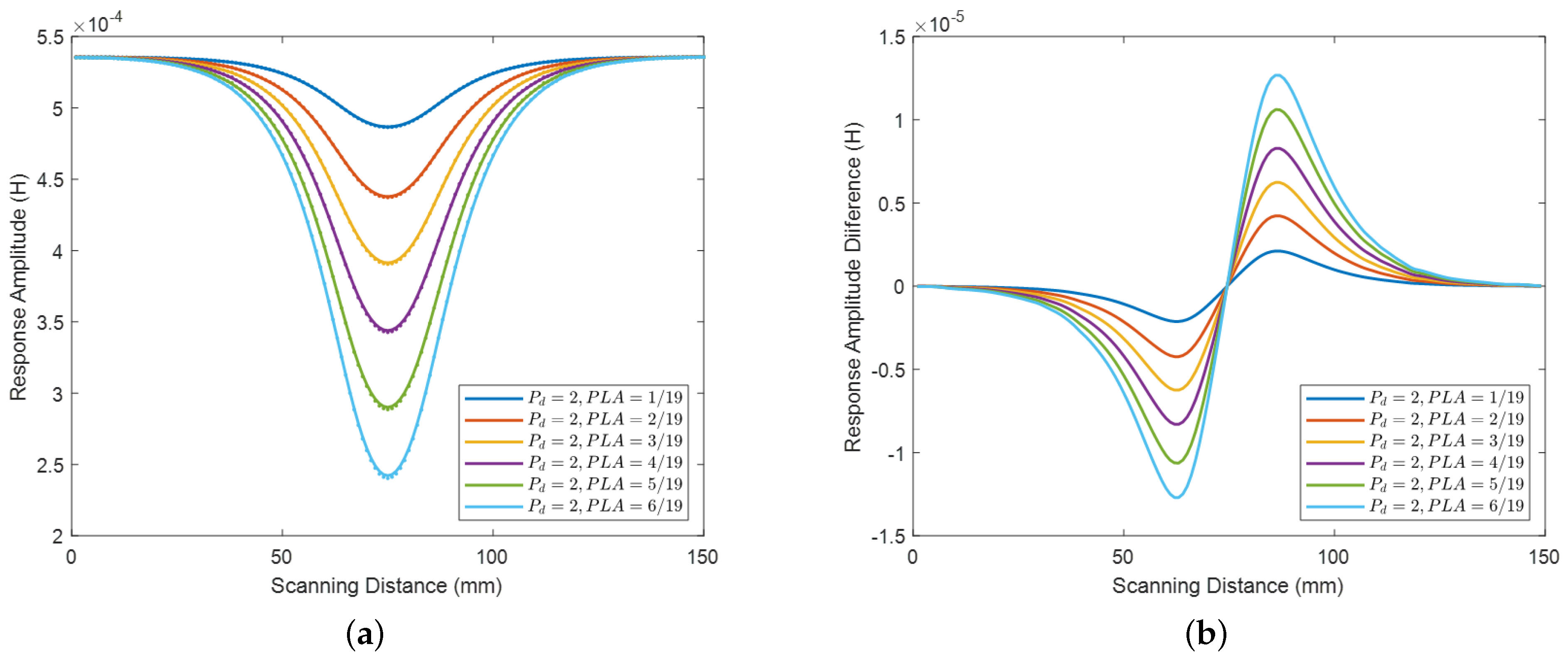
Accordingly, the variations in the self-inductance of the coil are simulated and recorded. Figure 2 illustrates the simulated signals produced by defects situated on Layer 2, with defects lengths ranging from 5 to 20 mm. Specifically, Figure 2a represents the original simulated signal, while Figure 2b shows the corresponding differential of the original signal. The results demonstrate that the axial length of the flaw can be determined based on the measured coil inductance variation. Additionally, Figure 3 shows the simulation signals generated by defects with varying cross-sectional areas and a length of 20 mm. Figure 3a represents the original simulated signal, and Figure 3b shows the corresponding differential signal. The results indicate that the coil’s inductance response is highly correlated with the flaw’s cross-sectional area. The aforementioned results effectively reveal the relationships between the coil inductance variation and the axial length as well as the cross-sectional area of the defects.
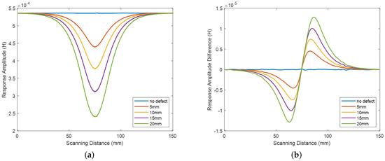
Figure 2.
Inductance variation simulation of the self−inductance coil with flaws of different axial lengths, with PLA = 6/19, (a) Original simulated signal (b) Differential of the original signal.
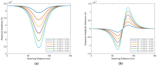
Figure 3.
Inductance variation simulation of the self−inductance coil with flaws of different cross-sectional area, with a length of 20 mm, (a) Original simulated signal (b) Differential of the original signal.
2.2. Data Processing Procedure
In order to prepare and analyze the acquired response signals obtained from the measured coil inductance in the experiment, several sequential steps are followed, as shown in Figure 4. Firstly, the inductance of the coil used in the inspection method is measured, providing a baseline reference. Subsequently, to enhance signal quality, filtering and smoothing techniques are applied to mitigate noise and the signal baseline are removed. Subsequently, differential analysis is conducted to accentuate variations and changes in the signal characteristics. Finally, relevant features encompassing attributes such as amplitude, frequency and shape patterns are extracted from the processed signals. These methodical steps ensure effective processing and analysis of the experimental data, thus enabling accurate detection and assessment of flaws present in the bridge cables.

Figure 4.
Experimental data processing workflow.
3. Experiment Setup
To validate the proposed numerical simulation model and explore the relationship between coil inductance response and flaw size and position, a flaw inspection experiment was carried out at room temperature. The experiment was primarily conducted using a signal sampling and processing unit, a system control unit, and a display module.
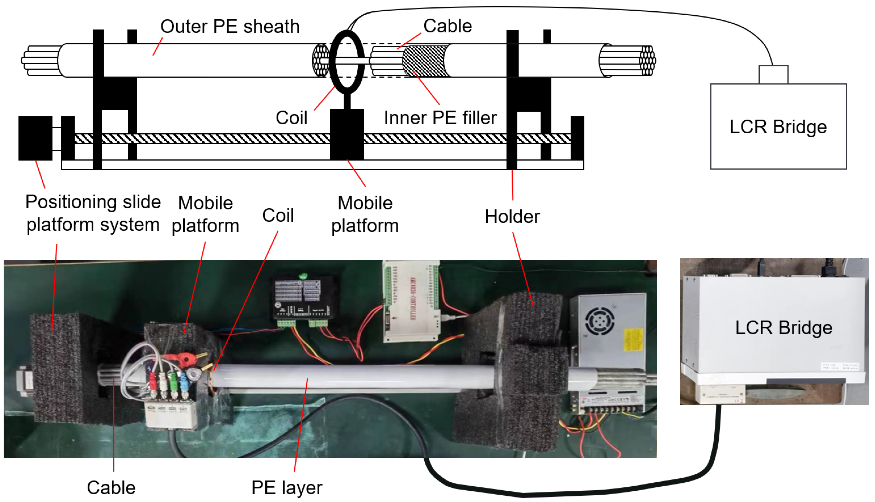
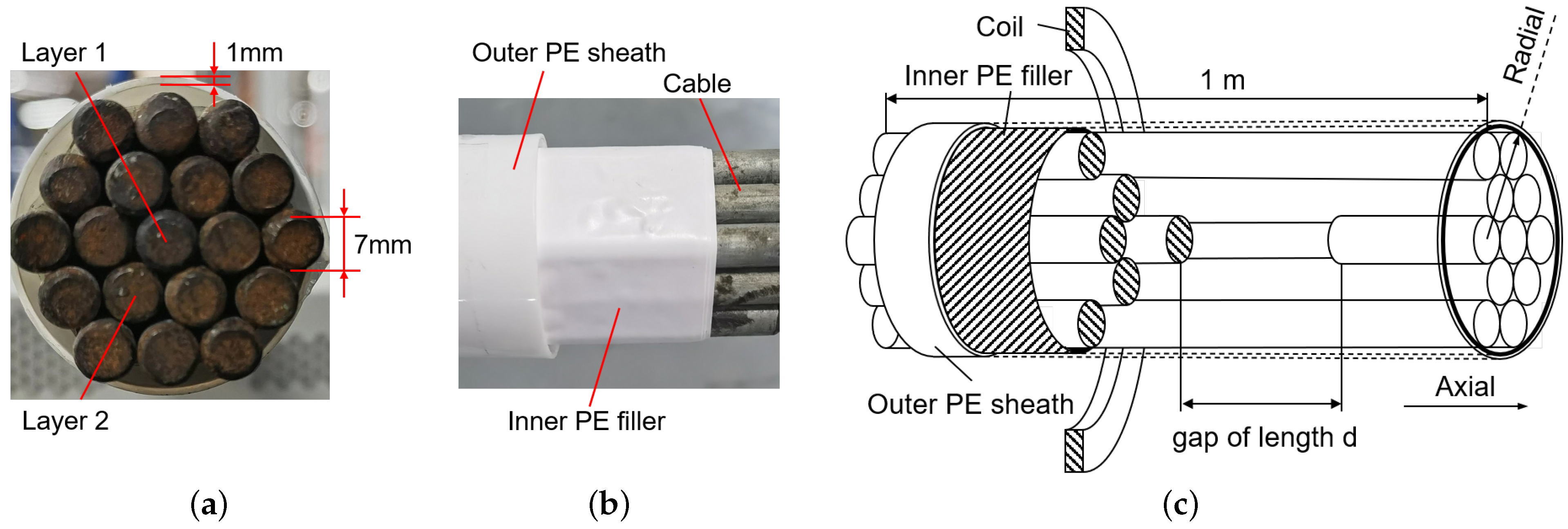
The signal sampling unit, depicted in Figure 5, was comprised of a cable, PE sheaths, a cable holder, and a positioning slide platform system. As shown in Figure 6a, the cable specimen consisted of parallel single-stranded galvanized steel wires arranged in a specific order, with a diameter of 7 mm. The whole cable was surrounded by PE material, which included a 1 mm PE sheath and six layers of 0.2 mm PE tape. The PE tape filled the space between the outer sheath and the cable. Flaws were systematically deployed in the middle of different layers. The diagrams of the flaw are presented in Figure 6c, where the axial length of the flaw is denoted by d. To generate flaws of varying axial length d, the distance between both sides of the wires was incrementally adjusted from 0 mm to 40 mm with a step size of 10 mm.
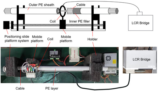
Figure 5.
Signal Sampling Unit Diagram.
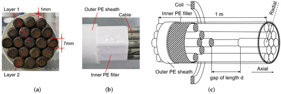
Figure 6.
Flaw position diagram (a) Sectional diagram (b) Side diagram (c) Diagram of the flaw.
The cable specimen was suspended by holders situated above the slide-way and traversed over a self-induction coil that was fixed to a mobile platform. The coil was composed of 300 winding of 0.3 mm enameled copper wire and possessed an external diameter of 80 mm, an inner diameter of 70 mm, and a thickness of 2.1 mm. The coil’s inductance was accurately measured in real-time with an LCR bridge. A frequency range from 1000 Hz to 10,000 Hz was chosen to analyze the influence of the excitation frequency on the coil’s self-inductance response and determine the most appropriate excitation frequency. Five anchor frequencies were selected to divide the frequency band, and the logarithm of the frequencies was employed to reduce the range span. The experiment involved moving the coil along the slide-way to detect flaws inside a cable. The scanning distance was 300 mm. The signals were then uploaded to a host computer for display and processing. Figure 7 presents the entire experimental procedure. Table 1 shows the detailed experimental parameters. The experiments are labeled as , where i represents the flaw location and j represents the flaw cross-sectional area on the i-th layer. For instance, denotes the situation of and .

Figure 7.
Entire experiment system flowchart.

Table 1.
The whole experiment parameter.
4. Experimental Result Analysis
In this section, the experiment was conducted under the condition depicted in Section 3. The variation of the coil’s self-inductance response was measured, and the processed experimental results were employed to explore the corresponding relations between the coil’s self-inductance and the flaw axial length as well as the flaw cross-sectional area.
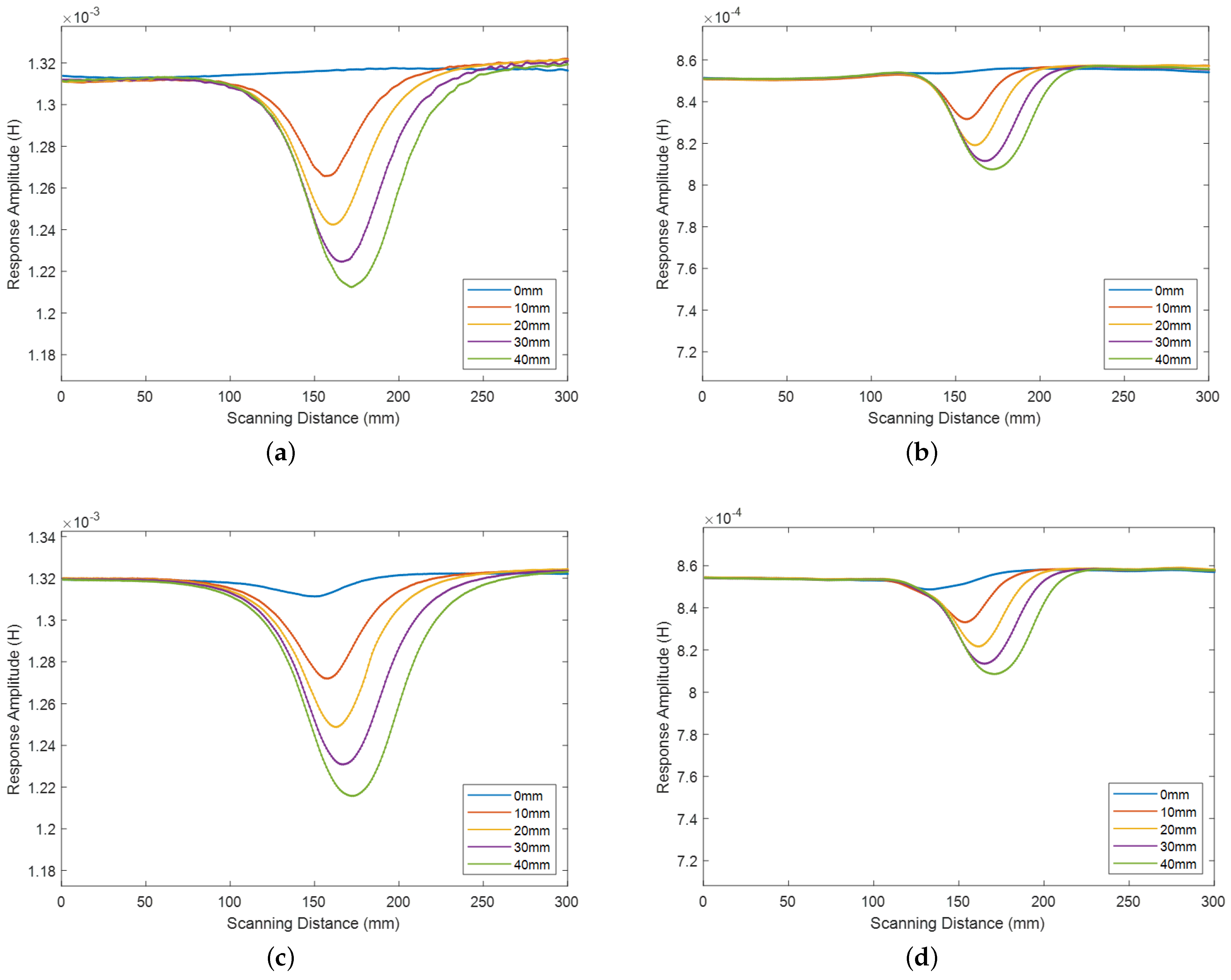
Figure 8 presents a preliminary comparison of the effects of the PE sheath on detected signals at two representative frequencies under . The detection results without a 1 mm thick PE sheath are shown in Figure 8a,b for excitation frequencies of 1000 Hz and 10,000 Hz, respectively. Figure 8c,d depict the detection results with the sheath for the same excitation frequencies. The data was smoothed and presented on a uniform scale. The distance between one side of the flaw and the sensor was positioned at 150 mm, while the other side was incrementally adjusted. Notably, the “0 mm” condition denotes that the two sides of the flaw were in contact. The presented graphs demonstrate that the signal response exhibited a decrease prior to the flaw front edge and an increase following the flaw rear edge. Moreover, the coil achieved its minimum inductance response during scanning when passing through the center of the flaw. It is noteworthy that when excited with higher frequencies, the coil demonstrated a higher inductance response baseline with reduced noise but lower response amplitude. The variation in the slope and shape of the response curve revealed a correlation between the coil self-inductance and flaw size, where longer axial lengths produced broader and more prominent response curves. The comparison of these results demonstrated that the presence of the PE sheath had a little impact on the amplitude of the inductance response, meanwhile, it exhibited a denoising effect to some extent. These findings provide the groundwork for the further experiments. Subsequent experiments will be conducted using the same cable with the PE layer.
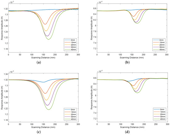
Figure 8.
Inductance variation of different length flaws at different situations (a) Result without PE sheath under 1000 Hz (b) Result without PE sheath under 10,000 Hz (c) Result with PE sheath under 1000 Hz (d) Result with PE sheath under 10,000 Hz.
4.1. Analysis of Flaw Length Based on Flaw Position
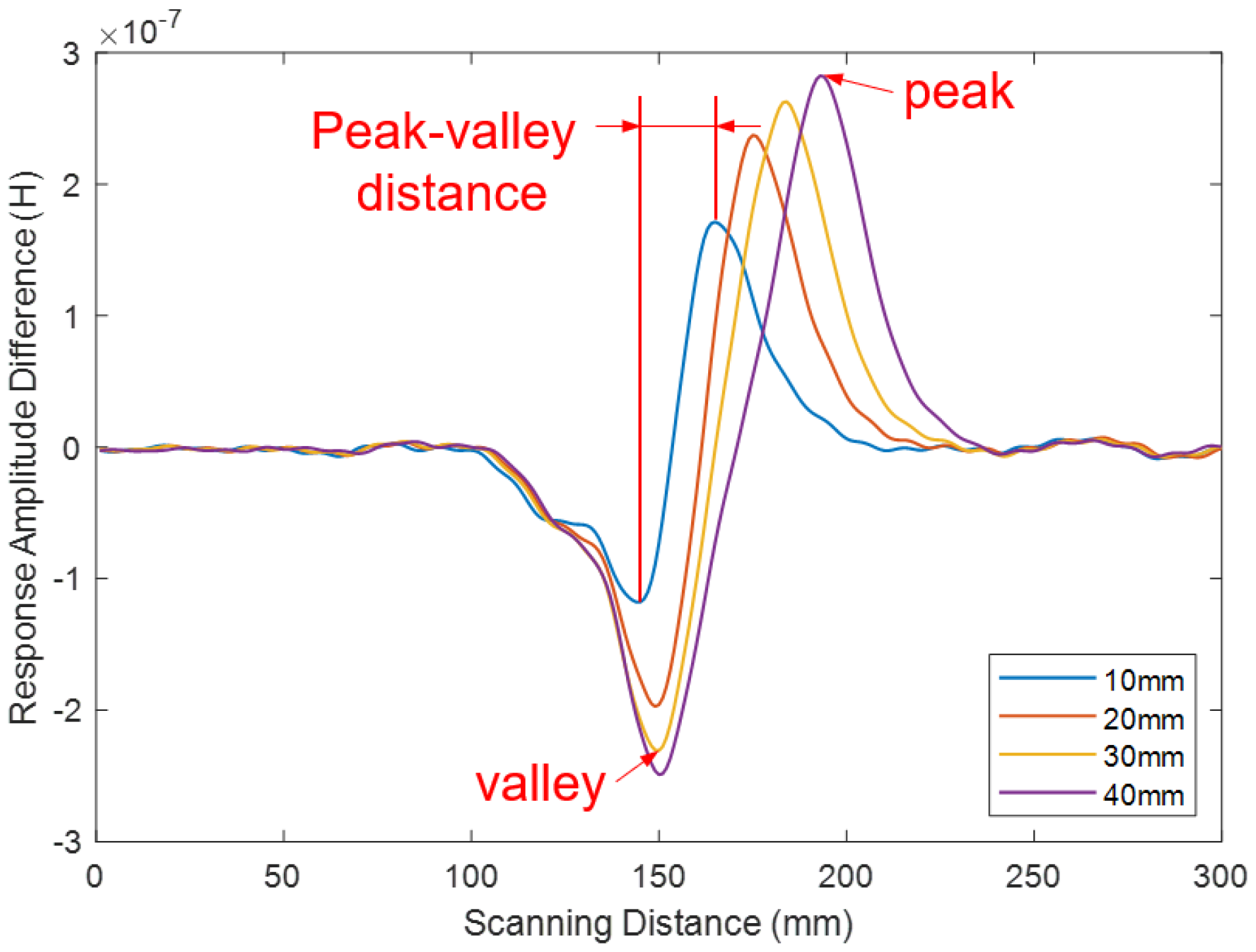
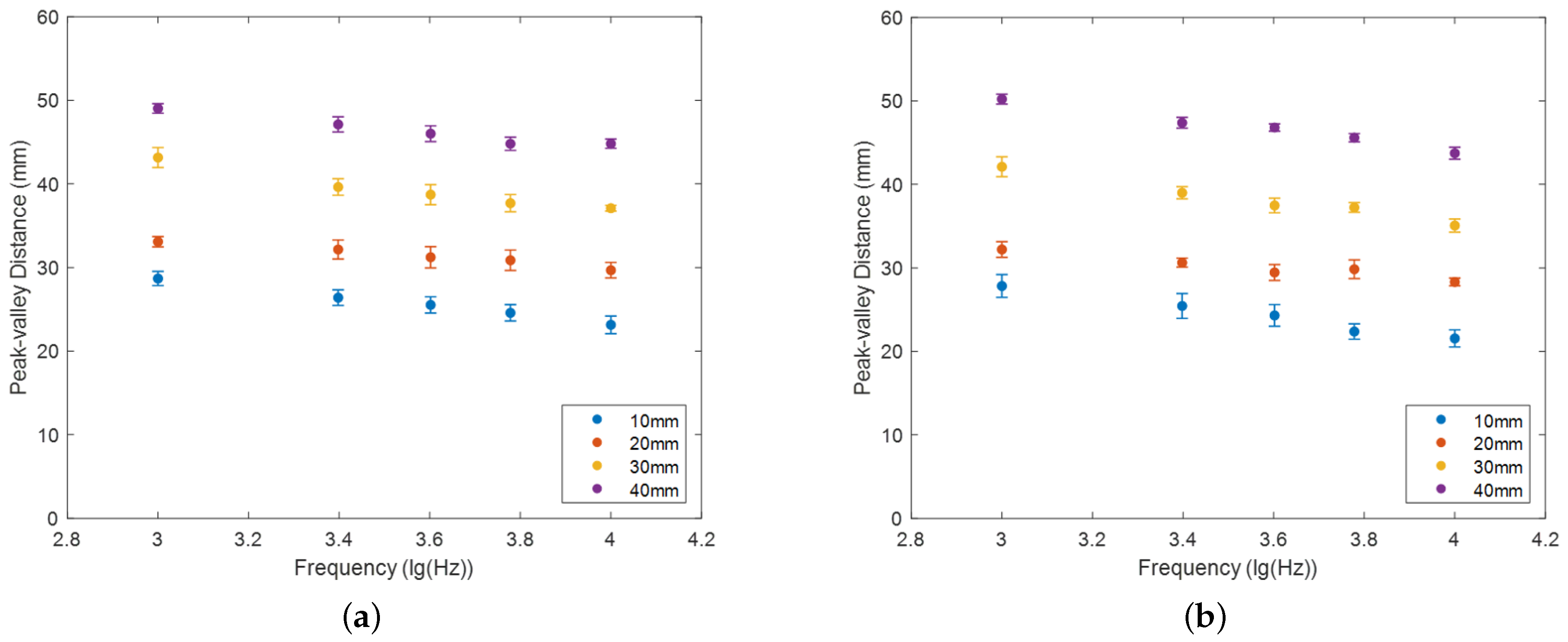
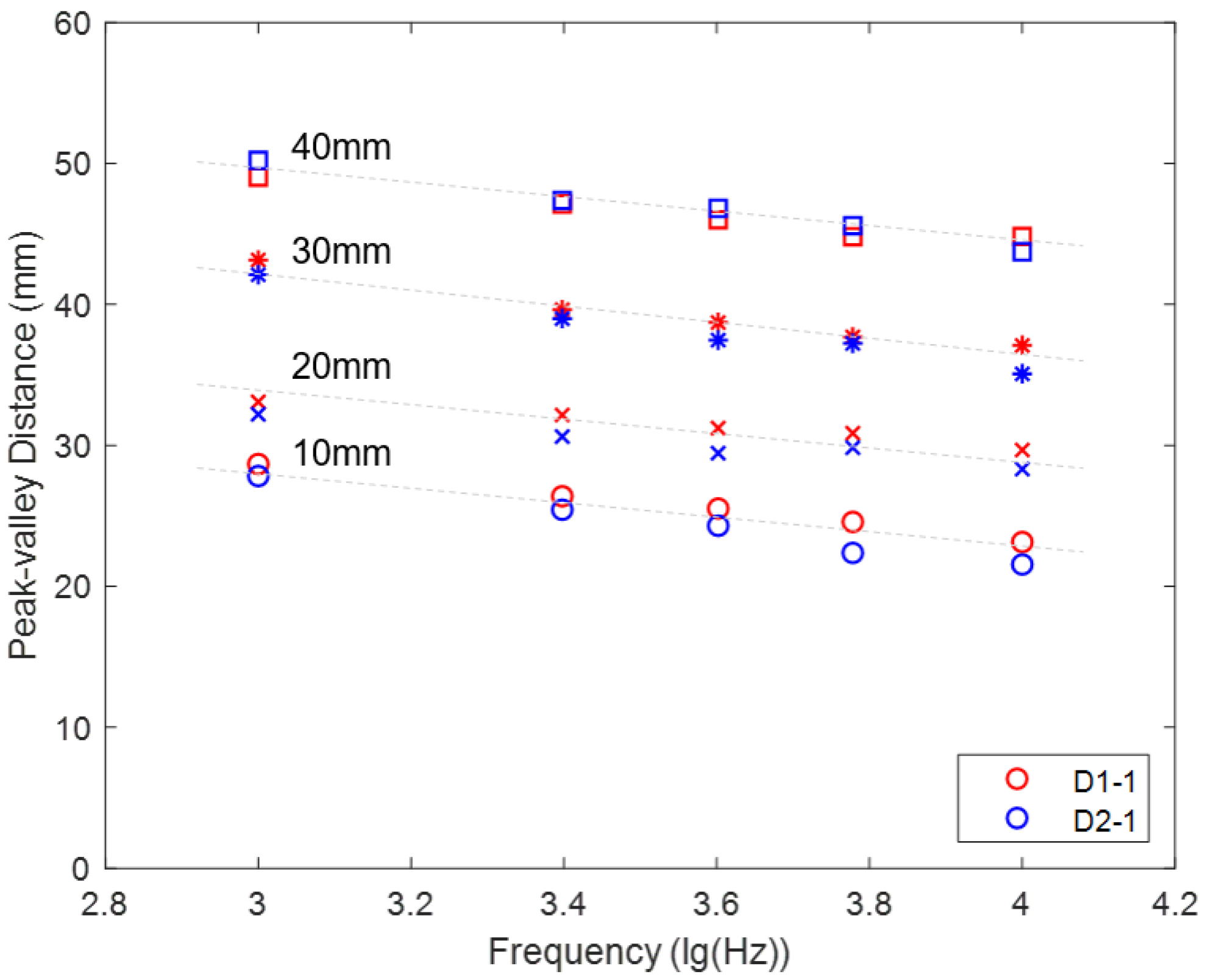
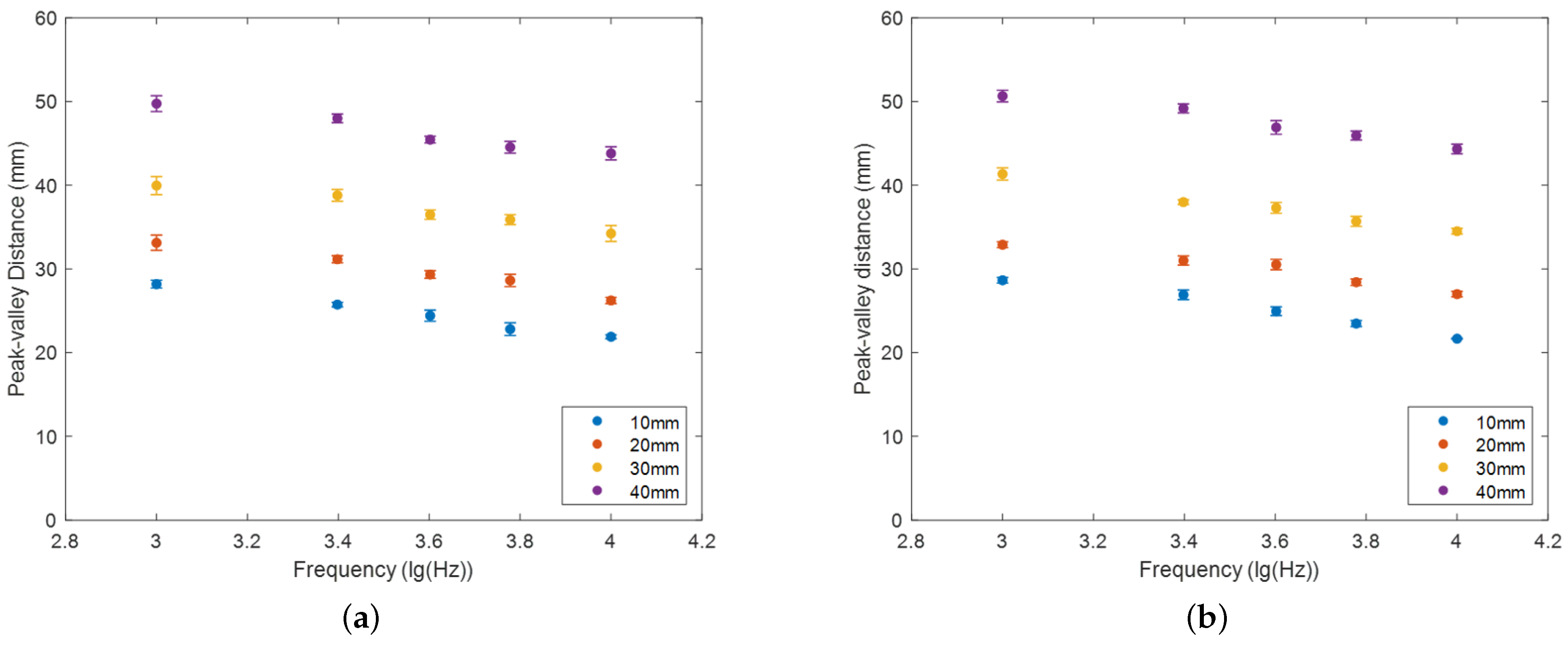
To investigate and quantify the mapping relation between flaw axial length and response curve width, the differentials of the response curves were calculated to analyze the shape change of the signal curves. Figure 9 presents typical differential curves of different length flaws at 10,000 Hz excitation frequency under . The peak-valley distances, which are defined as the interval between the minimum and maximum extreme points of each curve, clearly clarify the relationship between flaw axial length and inductance response width. Therefore, the peak-valley distances of were obtained, and the experiment was repeated five times to calculate the standard deviation and add error bars. All results are assembled in Figure 10a, where the x-axis adopts the logarithmic form of the anchor frequencies, and the y-axis represents the peak-valley distances.
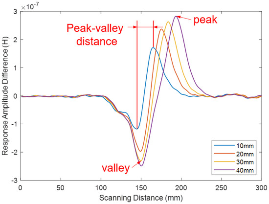
Figure 9.
Typical response differential curves at 10,000 Hz excitation frequency for different axial lengths.
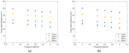
Figure 10.
Comparison of peak−valley distances for one−column flaw on different position (a) (b) .
Furthermore, in order to minimize the influence of the flaw location, a follow-up experiment was carried out under . The experiment was repeated five times to obtain the mean and standard deviation values, which are presented as error bars in Figure 10b. Both Figure 10a,b demonstrate a downward trend in the peak-valley distance as the excitation frequency increases.
The standard deviations under both and exhibit a relative high dispersion level, particularly for short flaw length situations. Based on this analysis, the peak-valley distances of and were compiled in Figure 11. It can be observed that there is a relatively good overlap for longer flaw lengths, whereas some slight deviation is apparent for shorter flaw lengths. However, distinct boundaries between the situations of different flaw lengths remain clearly visible, which indicates that this deviation does not significantly affect boundary determination. Consequently, it can be concluded that the self-inductive coil consistently responds to changes in the axial length of the flaw, regardless of its location.
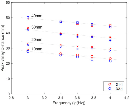
Figure 11.
Peak−valley distance comparison of different length flaws on different layers.
4.2. Analysis of Flaw Length Based on Flaw Cross-Sectional Area
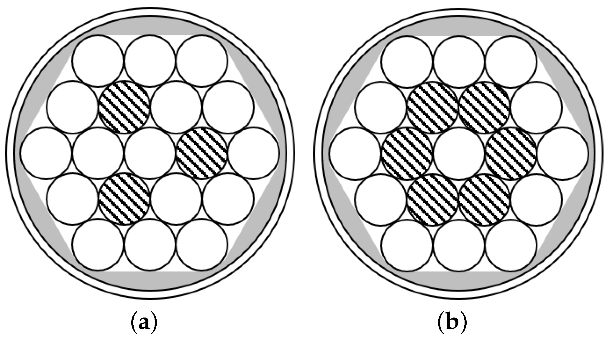
This section focuses on comparing the effects of different defect cross-sectional areas on peak-valley distances. Figure 12a,b depict the distributions of flaws with varying cross-sectional areas, identified as and respectively, where the hatched sections illustrate the presence of flaws. Figure 13a,b show the corresponding peak-valley distance comparisons for each situation. It can be observed that both and exhibit a similar variation trend and follow the same sequence rule compared to the response under . Furthermore, they demonstrate low standard deviations. It suggests that increasing the flaw cross-sectional area significantly enhances detection accuracy and repeatability.
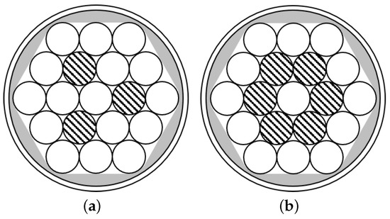
Figure 12.
Distribution of the flaws (a) on Layer 2 (b) on Layer 2.
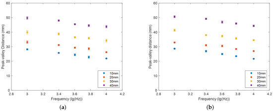
Figure 13.
Comparison of peak−valley distances for flaws with different sectional areas (a) on Layer 2 (b) on Layer 2.
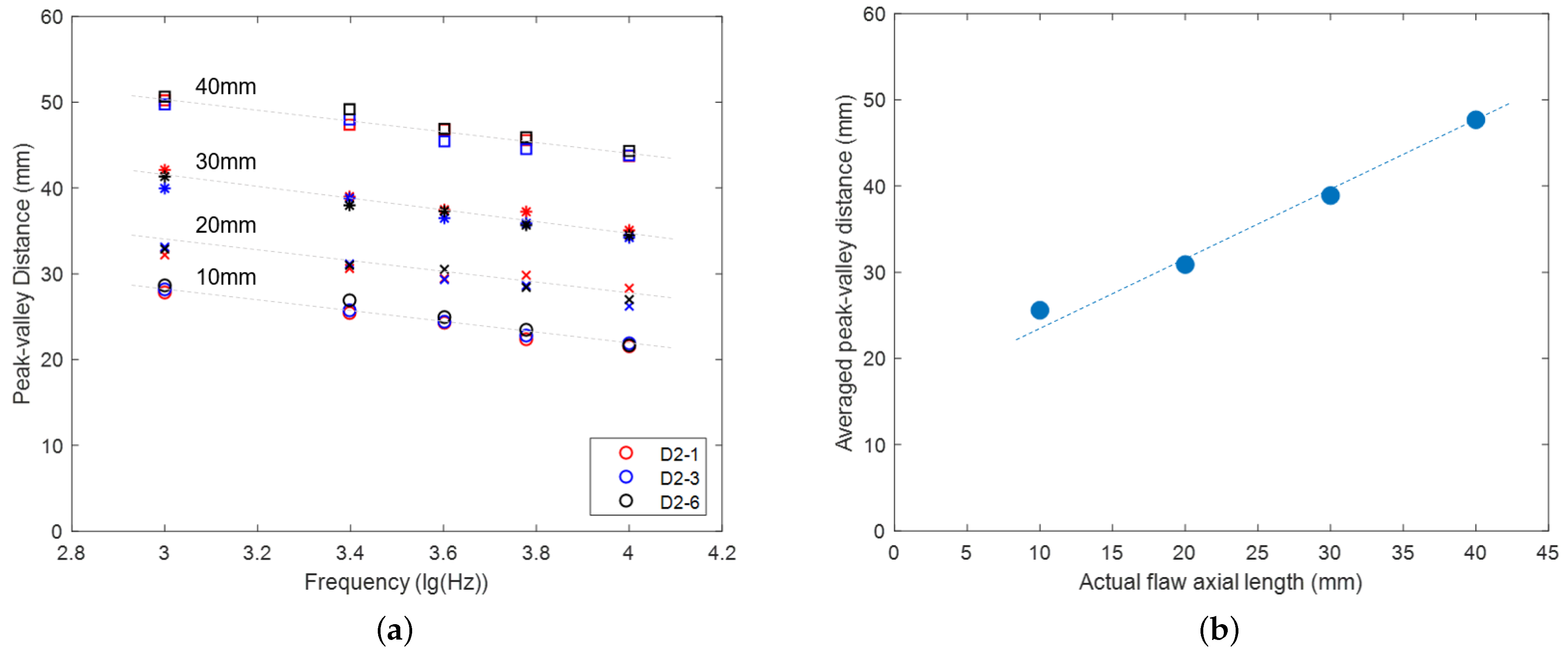
Figure 14a compares the peak-valley distances of , , and at the anchor points. It is evident that clear differentiation exists among the peak-valley distances for various flaw lengths. Additionally, the peak-valley distances show a substantial degree of overlap under situations with different flaw cross-sectional area, indicating that the cross-sectional area has little effect on the response of flaw axial length. By weighing the effect of the excitation frequency on the peak-valley distance dispersion degree and the response amplitude, the follow-up analysis was deployed at 2500 Hz. Combined with the above conclusion, the self-inductance coil response of the flaw axial length is minimally affected by the flaw position and the flaw cross-sectional area on the scanning plane. Therefore, flaw length information can be quantified without considering the influence of the above two factors. Figure 14b illustrates a linear relationship between the actual length of a flaw in the axial direction and its corresponding peak-valley distance, where the peak-valley distance is averaged from the result obtained from the various cross-sectional area situations shown in Figure 14a.
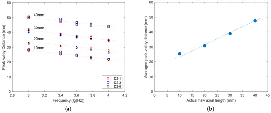
Figure 14.
Diagram of the relationship between flaw axial length and peak−value distance (a) Peak−valley distance comparison of different cross−sectional area flaws on Layer 2 (b) Graph of relationship between flaw axial length and averaged peak−valley distance at 2500 Hz excitation frequency.
4.3. Analysis of Response Amplitude Based on Flaw Position
This section focuses on analyzing the influence of the flaw position on the response amplitude. As depicted in Figure 8, the response peaks of flaws are affected by both the flaws and basic response drifts. To accurately quantify the response amplitude, the underlying response drifts need to be eliminated. In the experiment, the response obtained under “no defect” conditions served as the baseline value for identifying the basic coil response drifts during scanning. Compensated responses were obtained by subtracting the essential drift value. Figure 15 shows the offset response values of flaws with different lengths at 2500 Hz excitation under and , where the baseline is located nearby the zero line. The basis values and were obtained by averaging the baseline values on either side of the peak value to minimize the influence of fluctuations. Based on the compensated response values, the absolute response amplitude was calculated ulteriorly using this formula:
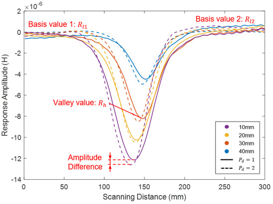
Figure 15.
Compensated response comparison of flaws with different lengths at 2500 Hz excitation frequency.
Table 2 presents the results of an experimental investigation into the effect of flaw position on the response amplitude under and for the same axial length. To quantify the impact of the flaw position, an uncertainty analysis was performed on the data. The analysis involved computing the absolute amplitudes and amplitude difference between the two situations. The results illustrated that the amplitude of was slightly smaller than that of due to the position of the flaw. Further analysis involved calculating the proportion of the amplitude difference to , which showed a relatively low level of difference. While the largest amplitude difference was observed for the 10 mm flaw, its impact within the range of uncertainty was still significantly lower than that of a one-unit increase in cross-sectional area. Therefore, this suggests that the impact of the flaw position on the response amplitude is relatively small within the experimental scope.

Table 2.
Inductance amplitude comparison under and .
4.4. Analysis of Response Amplitude Based on Flaw Cross-Section Area
This section presents a comparative analysis of the influence of the flaw cross-sectional area on the response amplitude. Experimental conditions for the investigation are outlined in Table 3.

Table 3.
The restricted experimental condition.
Figure 16a displays the offset response values of 10 mm flaws with different cross-sectional areas at 2500 Hz excitation frequency on Layer 2. To quantify the amplitude of each situation, the absolute amplitudes were calculated on the basis of Equation (6) and averaged. The results were presented in Figure 16b. The figure shows a clear trend in the response amplitude of the self-inductive coil as the flaw cross-sectional area decreases under . The response amplitude experiences significant attenuation, indicating a linear relationship between the flaw cross-sectional area and the self-inductive coil response amplitude. These findings reveal a positive correlation between the flaw cross-sectional area and the self-inductive coil response amplitude for flaws located at the same depth inside the cable.
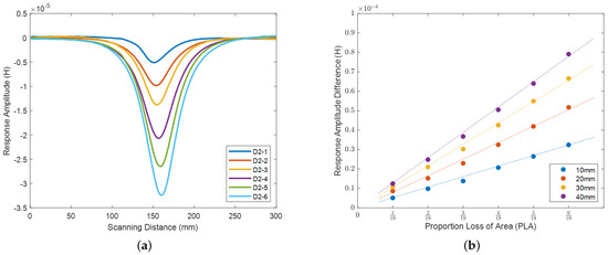
Figure 16.
Diagram of the relationship between flaw cross−sectional area and response amplitude (a) Compensated response comparison of a 10 mm flaw at 2500 Hz excitation frequency (b) Graph of the relationship between the flaw cross-sectional area and the corresponding absolute response amplitude at 2500 Hz excitation frequency.
5. Discussion and Conclusions
This paper presents a non-destructive inspection method for bridge cables based on the self-induction phenomenon, which utilizes a single self-induction coil search sensor. The self-induction coil of the proposed method offers various advantages that make it a potentially effective alternative for flaw detection. It requires less data processing and exhibits real-time responsiveness. Moreover, its lightweight design enables easy integration with robotic systems. Another advantage is its ability to provide a relative quantification of flaw size, which is a crucial factor for evaluating the condition of bridge cables. In this regard, Table 4 presents a comparative analysis of various cable flaw detection methodologies. To evaluate the effectiveness of the proposed method, this study examines the impact of various factors, including excitation frequency, flaw location, flaw axial length, and cross-sectional area on the inductance response. Firstly, a positive linear relationship is established between flaw axial length and the peak-valley distance of the response. This suggests that the method has the potential to assess the axial length of flaws based on the measured response. Secondly, a positive proportional correlation is observed between the self-inductance response amplitude and the cross-sectional area of flaws. This indicates that the proposed method can estimate the flaw’s cross-sectional area. The experimental results obtained in this study provide supporting evidence for the validation and effectiveness of the proposed method in flaw detection and assessment. While the proposed method has some limitations, such as the current experimental focus on three-layer cables, future research aims to expand the testing to include more layers. Additionally, feasibility assessments of the measurement system will be performed, and the method will be validated and calibrated on a larger scale to enable its practical implementation in real-life bridge assessments. Despite these considerations, the proposed method offers a optional solution for evaluating the condition of bridge cables, with the potential to enhance the safety and reliability of bridge structures.

Table 4.
Comparative analysis of cable flaw detection methodologies.
Author Contributions
Conceptualization, Z.F. and M.Z.; methodology, Z.F. and M.Z.; software, Z.F.; validation, Z.F. and M.Z.; formal analysis, Z.F.; investigation, M.Z.; resources, M.Z., N.D. and H.Q.; data curation, Z.F. and M.Z.; writing—original draft preparation, Z.F.; writing—review and editing, M.Z. and H.Q.; supervision, N.D. and H.Q.; project administration, N.D. All authors have read and agreed to the published version of the manuscript.
Funding
This research was funded by AIRS-SWET-Cooperation Engineering Center, the Guangdong Basic and Applied Basic Research Foundation under Grant No. 2019A1515111119 and No. 2021A1515010926 and the Shenzhen Science and Technology Program under Grant No. JSGG20210802154539015.
Institutional Review Board Statement
Not applicable.
Informed Consent Statement
Not applicable.
Data Availability Statement
The data presented in this study are available on request from the corresponding author.
Acknowledgments
The author would like to thank Zhao Zhang and Tengfei Su for their kindly suggestions in the scenario requirements definition and experiments method.
Conflicts of Interest
The authors declare no conflict of interest.
References
- Xu, Y.L. Making good use of structural health monitoring systems of long-span cable-supported bridges. J. Civ. Struct. Health Monit. 2018, 8, 477–497. [Google Scholar] [CrossRef]
- Farhangdoust, S.; Mehrabi, A. Health monitoring of closure joints in accelerated bridge construction: A review of non-destructive testing application. J. Adv. Concr. Technol. 2019, 17, 381–404. [Google Scholar] [CrossRef]
- Khedmatgozar Dolati, S.S.; Caluk, N.; Mehrabi, A.; Khedmatgozar Dolati, S.S. Non-Destructive Testing Applications for Steel Bridges. Appl. Sci. 2021, 11, 9757. [Google Scholar] [CrossRef]
- Dwivedi, S.K.; Vishwakarma, M.; Soni, A. Advances and researches on non destructive testing: A review. Mater. Today Proc. 2018, 5, 3690–3698. [Google Scholar] [CrossRef]
- Zolfaghari, A.; Kolahan, F. Reliability and sensitivity of visible liquid penetrant NDT for inspection of welded components. Mater. Test. 2017, 59, 290–294. [Google Scholar] [CrossRef]
- Manikandan, K.; Sivagurunathan, P.A.; Ananthan, S.; Moshi, A.A.M.; Bharathi, S.S. Study on the influence of temperature and vibration on indications of liquid penetrant testing of A516 low carbon steel. Mater. Today Proc. 2021, 39, 1559–1564. [Google Scholar] [CrossRef]
- Bado, M.F.; Casas, J.R. A review of recent distributed optical fiber sensors applications for civil engineering structural health monitoring. Sensors 2021, 21, 1818. [Google Scholar] [CrossRef]
- Sasy Chan, Y.W.; Wang, H.P.; Xiang, P. Optical Fiber Sensors for Monitoring Railway Infrastructures: A Review towards Smart Concept. Symmetry 2021, 13, 2251. [Google Scholar] [CrossRef]
- He, J.; Zhou, Z.; Jinping, O. Optic fiber sensor-based smart bridge cable with functionality of self-sensing. Mech. Syst. Signal Process. 2013, 35, 84–94. [Google Scholar] [CrossRef]
- Zhang, C.; Ge, Y.; Hu, Z.; Zhou, K.; Ren, G.; Wang, X. Research on deflection monitoring for long span cantilever bridge based on optical fiber sensing. Opt. Fiber Technol. 2019, 53, 102035. [Google Scholar] [CrossRef]
- Oh, S.j.; Jung, M.j.; Lim, C.; Shin, S.c. Automatic detection of welding defects using faster R-CNN. Appl. Sci. 2020, 10, 8629. [Google Scholar] [CrossRef]
- Schaal, C.; Bischoff, S.; Gaul, L. Damage detection in multi-wire cables using guided ultrasonic waves. Struct. Health Monit. 2016, 15, 279–288. [Google Scholar] [CrossRef]
- Zhang, P.; Tang, Z.; Duan, Y.; Yun, C.B.; Lv, F. Ultrasonic guided wave approach incorporating SAFE for detecting wire breakage in bridge cable. Smart Struct. Syst. 2018, 22, 481–493. [Google Scholar]
- Hong, X.; Zhou, J.; He, Y. Damage detection of anchored region on the messenger cable based on matching pursuit algorithm. Mech. Syst. Signal Process. 2019, 130, 221–247. [Google Scholar] [CrossRef]
- Selim, H.; Delgado-Prieto, M.; Trull, J.; Pico, R.; Romeral, L.; Cojocaru, C. Defect reconstruction by non-destructive testing with laser induced ultrasonic detection. Ultrasonics 2020, 101, 106000. [Google Scholar] [CrossRef]
- Wang, X.; Niederleithinger, E.; Hindersmann, I. The installation of embedded ultrasonic transducers inside a bridge to monitor temperature and load influence using coda wave interferometry technique. Struct. Health Monit. 2022, 21, 913–927. [Google Scholar] [CrossRef]
- Zolfaghari, A.; Zolfaghari, A.; Kolahan, F. Reliability and sensitivity of magnetic particle nondestructive testing in detecting the surface cracks of welded components. Nondestruct. Test. Eval. 2018, 33, 290–300. [Google Scholar] [CrossRef]
- Tout, K.; Meguenani, A.; Urban, J.P.; Cudel, C. Automated vision system for magnetic particle inspection of crankshafts using convolutional neural networks. Int. J. Adv. Manuf. Technol. 2021, 112, 3307–3326. [Google Scholar] [CrossRef]
- Chen, Y.; Feng, B.; Kang, Y.; Liu, B.; Wang, S.; Duan, Z. A Novel Thermography-Based Dry Magnetic Particle Testing Method. IEEE Trans. Instrum. Meas. 2022, 71, 9505309. [Google Scholar] [CrossRef]
- Shi, Y.; Zhang, C.; Li, R.; Cai, M.; Jia, G. Theory and application of magnetic flux leakage pipeline detection. Sensors 2015, 15, 31036–31055. [Google Scholar] [CrossRef]
- Liu, B.; Luo, N.; Feng, G. Quantitative Study on MFL Signal of Pipeline Composite Defect Based on Improved Magnetic Charge Model. Sensors 2021, 21, 3412. [Google Scholar] [CrossRef]
- Oh, C.K.; Joh, C.; Lee, J.W.; Park, K.Y. Corrosion Detection in PSC Bridge Tendons Using Kernel PCA Denoising of Measured MFL Signals. Sensors 2020, 20, 5984. [Google Scholar] [CrossRef]
- Ni, Y.; Zhang, Q.; Xin, R. Magnetic flux detection and identification of bridge cable metal area loss damage. Measurement 2021, 167, 108443. [Google Scholar] [CrossRef]
- Ono, K. Review on structural health evaluation with acoustic emission. Appl. Sci. 2018, 8, 958. [Google Scholar] [CrossRef]
- Xin, H.; Cheng, L.; Diender, R.; Veljkovic, M. Fracture acoustic emission signals identification of stay cables in bridge engineering application using deep transfer learning and wavelet analysis. Adv. Bridge Eng. 2020, 1, 6. [Google Scholar] [CrossRef]
- Li, G.; Zhao, Z.; Li, Y.; Li, C.Y.; Lee, C.C. Preprocessing Acoustic Emission Signal of Broken Wires in Bridge Cables. Appl. Sci. 2022, 12, 6727. [Google Scholar] [CrossRef]
- Casas, J.R.; Moughty, J.J. Bridge damage detection based on vibration data: Past and new developments. Front. Built Environ. 2017, 3, 4. [Google Scholar] [CrossRef]
- Saidin, S.S.; Jamadin, A.; Abdul Kudus, S.; Mohd Amin, N.; Anuar, M.A. An overview: The application of vibration-based techniques in bridge structural health monitoring. Int. J. Concr. Struct. Mater. 2022, 16, 69. [Google Scholar] [CrossRef]
- Zarbaf, S.E.H.A.M.; Norouzi, M.; Allemang, R.; Hunt, V.; Helmicki, A.; Venkatesh, C. Vibration-based cable condition assessment: A novel application of neural networks. Eng. Struct. 2018, 177, 291–305. [Google Scholar] [CrossRef]
- Machorro-Lopez, J.M.; Valtierra-Rodriguez, M.; Amezquita-Sanchez, J.P.; Carrion-Viramontes, F.J.; Quintana-Rodriguez, J.A. A shannon entropy-based methodology to detect and locate cables loss in a cable-stayed bridge. Int. J. Appl. Mech. 2021, 13, 2150063. [Google Scholar] [CrossRef]
- Peng, Z.; Li, J.; Hao, H. Long-term condition monitoring of cables for in-service cable-stayed bridges using matched vehicle-induced cable tension ratios. Smart Struct. Syst 2022, 29, 167–179. [Google Scholar]
- Yanez-Borjas, J.J.; Machorro-Lopez, J.M.; Camarena-Martinez, D.; Valtierra-Rodriguez, M.; Amezquita-Sanchez, J.P.; Carrion-Viramontes, F.J.; Quintana-Rodriguez, J.A. A new damage index based on statistical features, PCA, and Mahalanobis distance for detecting and locating cables loss in a cable-stayed bridge. Int. J. Struct. Stab. Dyn. 2021, 21, 2150127. [Google Scholar] [CrossRef]
- Ren, J.; Zhang, B.; Zhu, X.; Li, S. Damaged cable identification in cable-stayed bridge from bridge deck strain measurements using support vector machine. Adv. Struct. Eng. 2022, 25, 754–771. [Google Scholar] [CrossRef]
- Van Bladel, J.G. Electromagnetic Fields; John Wiley & Sons: Hoboken, NJ, USA, 2007; Volume 19. [Google Scholar]
- Guru, B.S.; Hiziroglu, H.R. Electromagnetic Field Theory Fundamentals; Cambridge University Press: Cambridge, UK, 2009. [Google Scholar]
Disclaimer/Publisher’s Note: The statements, opinions and data contained in all publications are solely those of the individual author(s) and contributor(s) and not of MDPI and/or the editor(s). MDPI and/or the editor(s) disclaim responsibility for any injury to people or property resulting from any ideas, methods, instructions or products referred to in the content. |
© 2023 by the authors. Licensee MDPI, Basel, Switzerland. This article is an open access article distributed under the terms and conditions of the Creative Commons Attribution (CC BY) license (https://creativecommons.org/licenses/by/4.0/).

