Article

Pullout Behavior of a Polymeric Strap in Compacted Dry Granular Material

1
Faculty of Mining, Geology and Petroleum Engineering, University of Zagreb, 10000 Zagreb, Croatia
2
Faculty of Civil Engineering and Architecture Osijek, Josip Juraj Strossmayer University of Osijek, 31000 Osijek, Croatia
3
Faculty of Mechanical Engineering and Naval Architecture, University of Zagreb, 10000 Zagreb, Croatia
*
Author to whom correspondence should be addressed.
Appl. Sci. 2023, 13(15), 8606; https://doi.org/10.3390/app13158606
Submission received: 6 June 2023 / Revised: 21 July 2023 / Accepted: 23 July 2023 / Published: 26 July 2023

Abstract

:

Featured Application

The results of these tests can be very useful to engineers and designers in the design of reinforced soil structures. Pullout tests were performed on materials that are very often used in practice (crushed stone aggregate and polyester straps) for the construction of reinforced soil structures and for which there are no data in the published literature.

Abstract

Strap reinforcement is very commonly used as reinforcement material in mechanically stabilized earth walls (MSEW). Metal straps are mostly used as reinforcement material. However, in humid climates, where the risk of damage to metal straps due to corrosion is high, the use of geosynthetic straps is quite justified. In the Croatian coastal region, geosynthetic straps were used as reinforcement for two very high MSEWs. In both cases, the backfill material crushed stone aggregate from the neighboring site was used. According to the relevant standards, it is recommended that the backfill material should have a uniformity coefficient of Cu ≥ 4.0. To meet these requirements, it is usually necessary to sieve and crush the backfill material. To evaluate the influence of the uniformity coefficient on the friction interaction coefficient between a geosynthetic strap and a crushed stone aggregate, a series of pullout tests with different confining stresses and aggregate grain size distributions were conducted. The pullout tests were performed for three different uniformity coefficients of the crushed stone aggregate. The results confirmed the justification to use backfill material with a uniformity coefficient higher than 4.0. The pullout tests were performed with one strap, two closely spaced straps, and two separated straps. The results showed that lateral friction contributes to the pullout force in the amount of 16.1% of the total force.

1. Introduction

The pullout test is usually used to clarify the mechanism of interaction between soil and reinforcement and to estimate the degree of interaction (friction interaction coefficient), which is crucial for the design of mechanically stabilized earth walls (MSEWs). The interaction mechanism depends on the type of reinforcement element and the characteristics of the backfill material.
When selecting the backfill material for MSEWs, consideration is given to the material’s physical and mechanical properties as well as its cost. The crushed stone is a suitable material for the MSEWs from the stability and economical point of view and is therefore often used in the construction of the MSEWs [1]. The origin of crushed stone can be a quarry or local construction works. The process of obtaining the crushed stone aggregate mostly involves blasting rock, crushing, and sieving [2]. The price of this type of material depends on the grain size distribution, origin, and transport cost. Cost savings in this aspect should be considered during MSEW construction. According to [3], backfill material cost accounts for 33% of the total cost of an MSEW. Singh and Akthar [4] compared the price of an MSEW with different straps and geogrids. In their study, the costs of the backfill material account for more than 50% of the total cost of the MSEW. According to a performed cost analysis, using geogrids in combination with local soil as a backfill is considered the cheapest option. In contrast, [5] showed that the backfill of the MSEW accounted for 13% of the total cost.
According to [6], the recommended criteria for backfill material in MESWs include having less than 15% material passing sieve No. 200 and a plasticity index not exceeding 6.0. According to [7], for using default values of friction interaction coefficient for metallic straps, the backfill material must have a uniformity coefficient of Cu ≥ 4. For the backfill material that falls outside of these limits, pullout tests must be performed to determine the friction interaction coefficient. Weldu et al. [8] note that these requirements have disqualified a large number of produced aggregates or made their use in the construction of MSEWs more difficult and/or expensive. The authors also conducted an experimental study to investigate the effect of aggregate uniformity on the pullout resistance of ribbed steel straps when the aggregate uniformity coefficient ranged from 1.4 to 14.0. They concluded that the recommended friction interaction coefficient values are too conservative. The study showed that an aggregate backfill material with a uniformity coefficient as low as 1.4 can be used to design an MSEW with ribbed steel straps.
Most previous research focused on the interaction mechanism when the reinforcement was a metal strap or geogrid [9,10,11,12,13,14] or a geotextile/geogrid [15,16,17,18,19,20]. In the last 30 years, a small number of pullout tests have been performed with polyester straps to determine the friction interaction coefficient between the strap and the backfill material [21,22,23,24], the effect of normal stress and backfill material density on the strap–backfill material interaction [25], the effect of constrained dilatancy [25], and the deformation of the extensible reinforcement in the backfill material [26,27].
Most pullout tests were performed for tests under 100 kPa, which corresponds to a wall height of about 6 m [21,22,23,24,28]. Since polyester straps are used to construct increasingly higher walls [29,30,31], it is necessary to verify the behavior of the strap at higher stresses. Lo [21] studied the pullout resistance of polyester straps at low overburden stresses (20 kPa ¾ 100 kPa) for three different types of backfill material and showed that the friction interaction coefficient at low overburden stresses can be higher than the internal friction angle of the backfill material. The author explained this by the effect of constrained dilatancy and textured surface of the strap. The effect of dilatancy was also studied by the authors of [16,23]. They pointed out that when the strap is pulled out of the backfill material, the backfill material tends to dilate. Dilation occurs at the contact between the strap and the backfill material and at the zone in the backfill material adjacent to the strap. However, dilatancy can be prevented by the action of the surrounding backfill material, resulting in an increase in normal stress at the contact between the strap and the backfill material. Abdelouhab et al. [32] showed a higher value of the friction interaction coefficient in coarser backfill material. This difference is related to a higher backfill density and a higher backfill uniformity coefficient Cu, which results in a larger dilatancy angle and internal friction angle of the backfill material. The tests revealed that using two straps during testing resulted in a higher friction interaction coefficient. The authors stated that the possible causes of higher friction interaction coefficient when testing two parallel straps is the effect of the arching or dilatancy of the backfill material between the straps. Razazan et al. [33] also conducted pullout tests with two parallel polyester straps, where they investigated how the loop at the free end of the strap affects the interaction. They performed tests in poorly graded dry sand under normal stresses below 80 kPa using two parallel straps and one strap placed in a U shape. The results show that a U-shaped strap significantly increases the pullout resistance force and the friction interaction coefficient parameter. Pierozan et al. [23] studied the pullout resistance of polymer straps embedded in marginal tropical soils. They concluded that an increase in the typical characteristics of cohesive soil (e.g., fines content and plasticity index) leads to a decrease in pullout resistance, while an increase in the frictional properties of granular soil (e.g., friction angle) has the opposite effect. They also measured the vertical stress on the reinforcement during a pullout test. The tests showed that the stress during pullout regarding the initial state of stress increases significantly for clean sand and mixtures with lateritic weathering content below 25%. The obtained results also showed that the relationship between the actual and initial stresses is linear, which allows the prediction of the interaction friction coefficient. Agarwal et al. [24] conducted pullout tests with a polymeric strap using construction and demolition waste as backfill material. The results show that such a type of backfill material is suitable for the construction of MSEW structures. Vieria et al. [28] used the same backfill material to perform pullout tests with geosynthetics. They showed that the proper compaction of the backfill material is an essential requirement for all types of mechanically stabilized earth (MSE) structures. Park and Hong [34] showed that the width of the strap has a greater effect on the pullout force and tensile strength than the horizontal spacing of the reinforcement. They also proposed the effective area method based on the prediction of the strap-selected length as a more economically feasible design method.
In Croatia, several MSEWs with geosynthetic straps have been built in recent years, with two very high MSEWs standing out because of their dimensions. The first is the Strikići wall built in 2006, which is 26.8 m high and 500 m long. The second one is MSEW Sveta Trojica, built in 2012, which is 34 m high and 430 m long. Those MSEWs were built in the coastal region, where there is a high risk of corrosion of metal, so geosynthetic reinforcements were used instead of metal. Straps of polyester fibers coated with high-density polyethylene were used as reinforcement. Crushed stone from the local construction site was used as a backfill. In order to fulfill the backfill material installation criteria, the used aggregate required additional crushing and sieving.
In the construction of the MSEWs Strikići and Sveta Trojica, the polyester straps were laid in a zigzag pattern and connected to the precast T-shaped reinforced concrete panels. The straps were rolled up around a loop on the precast concrete panel in a pattern in which each loop covered two straps. Since the straps were very close to each other behind the panels, a mutual influence on the pullout resistance had to be considered. This loop was modeled in a pullout test with two separate straps. Previously, pullout tests with one and two parallel polyester straps were performed by Abdelouhab et al. [22,32]. The authors concluded that two parallel, closely spaced polyester straps resulted in a higher friction interaction coefficient as opposed to only one strap. Alfaro et al. [16] distinguished between 2D and 3D interaction mechanisms. The first refers to sheet reinforcement, and the second refers to strap reinforcement. The authors emphasized that, during pullout for the strap reinforcement interaction mechanism, the backfill material surrounding the reinforcement tends to dilate. However, the volume change is restrained by the surrounding non-dilating backfill material.
As the previous review of the literature has shown, there is a lack of studies that investigate the interaction between polyester straps and crushed stone aggregate. Consequently, very limited information regarding the friction interaction coefficient for polyester strap and crushed stone aggregate is available in the open literature. Therefore, the purpose of this work is to further investigate the mechanism of interaction for crushed stone aggregate and a polyester strap and the influence of granulometry on the friction interaction coefficient. The aim of the work can be divided into four main parts. The first part deals with the influence of the uniformity coefficient of crushed stone aggregate and the normal stress on the pullout mechanism. The second part deals with the stress–strain behavior of the straps. The third part deals with the determination of the lateral friction at the edges of the straps, and the fourth part discusses the obtained values of the friction interaction coefficient and compares them with values from previous studies. From the brief summary of studies related to geosynthetic straps and different backfill material shown in Table 1, it can be seen that there is a limited number of tests with crushed stone aggregates as backfill material.

2. Materials and Methods

The pullout tests on geosynthetic straps were performed in a large pullout box according to ASTM D6706-03 [35]. Setup with one strap, with two straps with a horizontal distance of 200 mm between the straps, and with two straps arranged next to each other with no space between them were used.

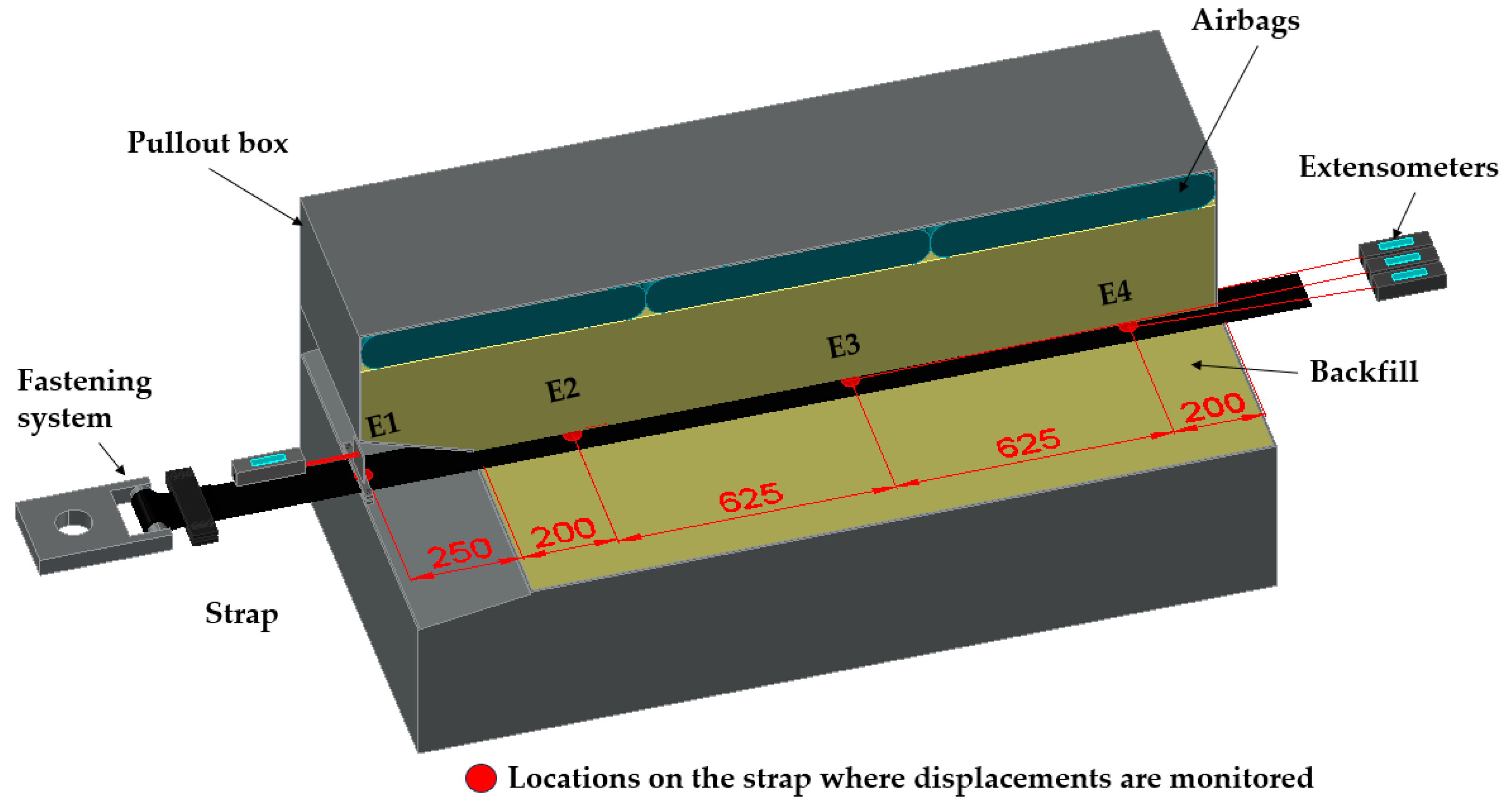
2.1. Testing Apparatus
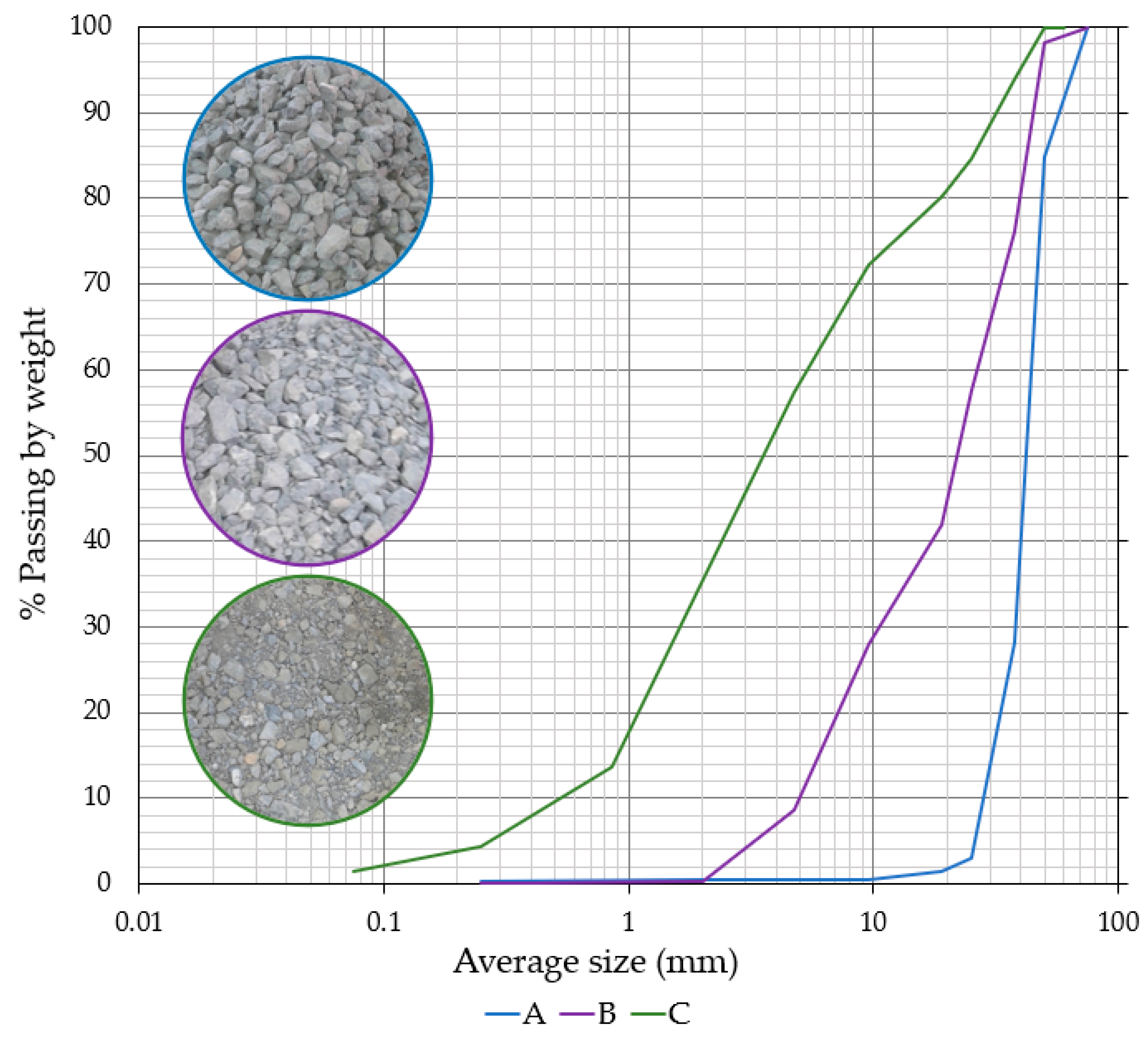
The pullout box (Figure 1) consists of four metal frames, each with a length of 1900 mm, a width of 900 mm, and a height of 200 mm. The frames are stacked and securely connected, allowing for an adjustable final box height ranging from 800 mm to 1200 mm. This box configuration allows for adjusting the amount of soil or aggregate sample inside and applying pullout force at two vertical levels. To mitigate the influence of the front wall on the test results, a 25 cm sleeve is installed at the front of the box. The strap is threaded through the sleeve and attached to the piston using a specifically designed fastening system on the front side of the box. At the rear side of the box, the strap is passed through the opening. Normal stress is applied by three airbags located under the top cover of the box. The top cover is connected to the top frame of the box and pressed by steel beams. The maximum pullout force that can be achieved is 80 kN, and it is generated by a piston attached to the front side of the box. Displacements are measured at four points along the installed strap using extensometers. A maximum extension of 200 mm can be measured with a sensitivity of 0.01 mm. The displacement of the first point (front side) represents the movement of the free section of the strap between the piston and sleeve. The other three points were distributed along the strap inside the box so that the displacements were monitored at the beginning part, middle part, and the end part of the emplaced strap. The more detailed description of the device can be found in the paper by Minažek and Mulabdić [36].

2.2. Test Materials

In this study, polymer geosynthetic straps were used as a reinforcement element. Crushed stone from a quarry was used as backfill material samples.

2.2.1. Backfill Material Properties

A total of five samples of the same material was used in different fractions for testing: 30/60 mm, 16/31.5 mm, 8/16 mm, 4/8 mm, and 0/4 mm. Each sample had a mass of 1500 kg. The mentioned fractions were used to make samples with a specific grain size distribution as shown in Figure 2. During placement and compaction of the backfill material in the pullout box, breakage of the grains occurs, changing the grain size distribution so that a new sample must be prepared for each test. The tests were performed with three different grain size distributions of the samples. The first sample was uniformly graded with a grain size ranging from 30 to 60 mm, labeled material A. The second sample was also uniformly graded with a grain size ranging from 4 to 60 mm, labeled material B, and the third sample was well graded with a grain size ranging from 0 to 60 mm, labeled material C. The backfill material sample properties are listed in Table 2. Friction and dilatancy angles of the samples were obtained from large direct shear tests [31]. The highest friction angle and dilatation angle were obtained for material A, while the lowest friction angle and dilatation angle were obtained for well-graded material C.

2.2.2. Geosynthetic Strap Properties

In all tests, polymer straps with discrete channels of densely packed high-tenacity polyester fibers (HTPET) wrapped with a polyethylene sheet were used. The polyester fibers serve as a load-bearing element, while the polyethylene sheet protects the fibers from structural damage. In the core of the polymeric strap, there are bundles of high tenacity polyester fibers. During the manufacturing process, the straps are passed through rollers to create grooves on the surface of the polymer sheathing, which increase friction on the surface of the strap. The straps were 90 mm wide and 5 mm thick and had a tensile strength of 100 kN. A typical cross-section of the polymer strap is shown in Figure 3.

2.3. Sample Preparation and Test Procedure

The pullout tests were performed with one strap, two straps closely placed, and two straps with 200 mm of horizontal spacing. The same test procedure was used in all tests. The only differences between test setups with one and two straps was in the connection system for the arrangement of one or two straps and in the location of the points for the displacement measurements.
The pullout tests with one strap setup were performed for backfill material labeled as A, B, and C under different normal stresses (50, 100, and 150 kPa), while the pullout tests with two straps were performed with well-graded backfill material C under one normal stress (50 kPa). An overview of the testing program is given in Table 3. Some tests were repeated. The number of tests shown in Table 3 represents the number of repeats of the same test setups. For the purpose of testing the geosynthetic strap, a specific fastening system was designed. In order to determine possible slippage of the geosynthetic strap on the fastening system and to determine the consistency and repeatability of the tests, individual tests were repeated several times. The repeat testing showed that no slippage occurred on the fastening system and that the displacements measured by extensometers along the length of the straps showed the same trend with increasing force. Based on these results, it was concluded that it was not necessary to repeat individual tests multiple times. For materials A and B, the tests were repeated at the same normal stresses, i.e., 50 kPa and 150 kPa for material A and normal stresses of 150 kPa material B. For material C, the tests were performed once, but an additional normal stress of 100 kPa was added for this material. The purpose of this additional test was to confirm that the point was on the failure line, which for materials A and B was defined by only two points. It also makes it easier to monitor the effects of the normal stress on the mobilization of the strap inside the box.
The prepared backfill material samples were placed in the box in 100 mm thick layers and vibro-compacted to the height of 400 mm. The polyester strap or two straps were placed on the layers of compacted backfill material in the center of the pullout box. The strap was treated across a sleeve on the front wall and connected to the piston. At the back side of the box, the strap was threaded out of the pullout box so that the length of the straps in the box during the pullout tests was constant at 1.65 m. The displacement of the straps was measured with four extensometers and with a displacement sensor on the piston. The arrangement of extensometers was different for test setups with one and two straps. For test setup with one strap, displacement was measured with three extensometers along the emplaced strap (200 mm from the sleeve, in the middle of the emplaced strap, and 200 mm from the back end of the box). For the tests with two straps, the displacement was also measured with four extensometers, two placed 200 mm from the sleeve on each strap and two placed 200 mm from the back side of the box. In the experiments carried out with one strap, the aim of monitoring the displacement was to determine the influence of grain size distribution and normal stress on the mobilization of the strap. For this reason, displacements were monitored at three locations on the inserted strap. In the tests with two straps, the objective was not only to determine the mobilization of the straps but also to determine whether simultaneous and parallel displacement occurs in both straps. The arrangement of the extensometers for the test setup with one strap is shown in Figure 4 and Figure 5 for two straps. After the strap was installed, the upper part of the backfill material was placed and compacted in layers. Normal stresses of 50 kPa, 100 kPa, and 150 kPa were applied to the top side of the backfill material sample using airbags. The tests were performed at a constant displacement rate of 1 mm/min, and the pullout force was measured using a load cell with a maximum capacity of 80 kN.

2.4. Interface Pullout Resistance for Polyester Strap and Crushed Stone

A total of sixteen pullout tests were performed in this study: twelve with one strap and four with two straps. According to Table 2, some tests were repeated, so the maximum pullout force (Pmax) was calculated as the mean value of maximum pullout forces from repeated tests. The shear stresses (τ) at the contact of the backfill material and the geosynthetic strap during the pullout tests were determined by the maximum pullout force (P) and the shear surface of the strap, where the width of the strap is b = 0.09 m and the length is l = 1.65 m:
τ = P/(2lb)
The strap pullout tests were performed to investigate the influence of the uniformity coefficient of crushed stone aggregate and the different normal stress on pullout resistance and the friction interaction coefficient. Friction interaction coefficient quantifies the interaction between the reinforcement and the backfill material, and according to Schlosser and Bastick [37], the friction interaction coefficient fS/GSY is given by
fS/GSY = Pmax/(sv2lb)
where Pmax is the maximum tensile/pullout force measured at the head of the reinforcement (kN), σv is the normal stress acting in the vertical direction at the level of the reinforcement strap (kPa), b is the reinforcement width (m), and l is the reinforcement length (m). For the cases where no reinforcement and soil interaction tests have been performed according to AASHTO [38] the friction interaction coefficient can be determined by Expression (3), in which the maximum value of friction angle (φ) is taken to be 36 degrees:
F* = 2/3tanφ
The experiments with two separated straps and two closely spaced straps were performed to investigate the influence of the lateral friction interaction coefficient. The lateral friction per strap can be calculated either from the difference of the maximum pullout forces for two separated and two closely spaced straps (Equation (2)) or from the difference of the pullout force for two separated straps and one strap (Equation (3)):
Ttr = (T2R − T2S)/2
Ttr = 2(T1 − T2S/2)
where Ttr is the lateral friction force per strap, T2R is the pullout force for two separate straps, T2S is the pullout force for two closely spaced straps, and T1 is the pullout force for one strap.

3. Results and Discussion

The results and their analysis are presented in this chapter. In the first part, the influence of the grain size distribution of the backfill material and the normal stress on the pullout mechanism were analyzed. Additionally, the damage of the polyester straps during the pullout tests in regard to the grain size distribution of the backfill material was discussed. In the second part, the stress–strain behavior of the straps was analyzed. The third part deals with the determination of the lateral friction at the edges of the straps and the fourth part discusses the obtained values of the friction interaction coefficient and compares them with values from previous studies.

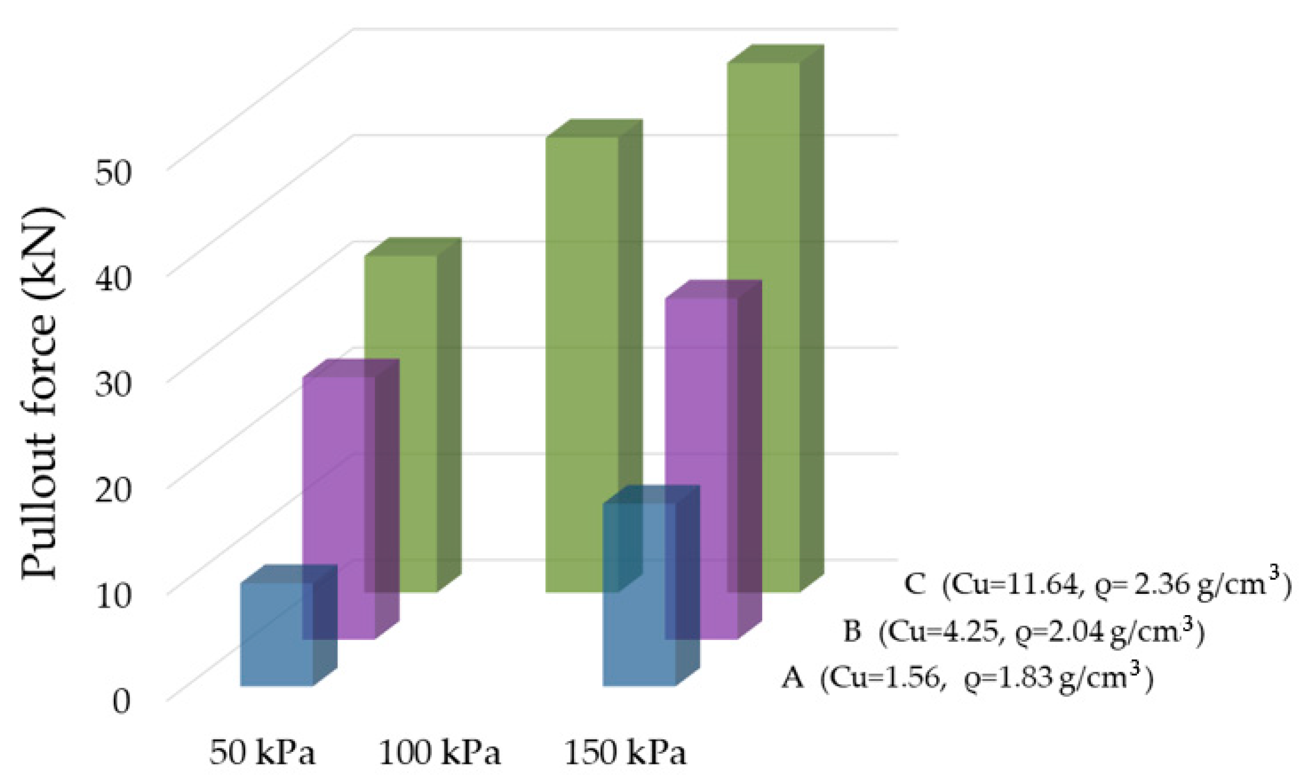
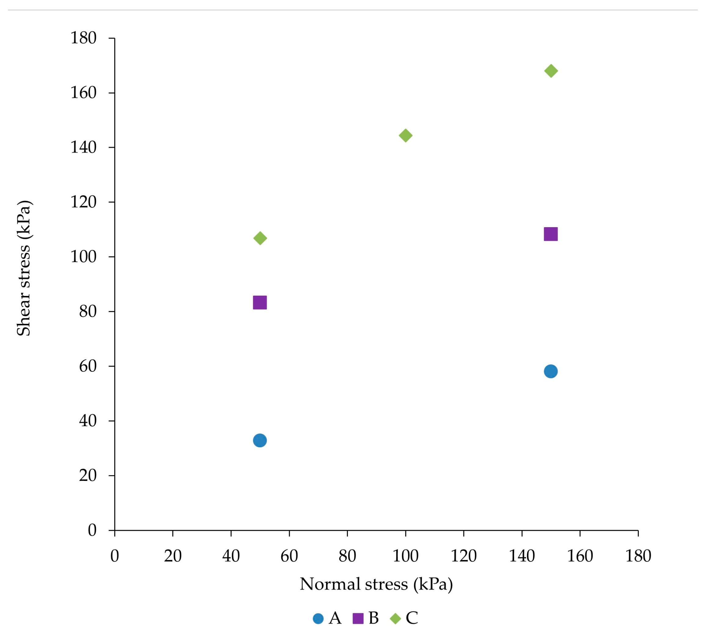
3.1. The Influence of the Grain Size Distribution of the Backfill Material and the Normal Stress on the Pullout Force of Geosynthetic Strap

The first backfill material, labeled A, had a grain size of 30 to 60 mm. This uniformly graded, narrow grain size range was chosen to study the effects of the lower density of the backfill on pullout resistance. As can be seen in Table 2, the mentioned material has the largest range of void ratio and, accordingly, the lowest density. The second and third backfill materials (labeled B and C) had wider grain size ranges. Backfill material B was also uniformly graded. Backfill material C was well graded with the smallest void ratio range and, accordingly, the highest density. With a wider grain size range, the density of the material is higher as the smaller grains fill the pores.
The influence of grain size distribution on the pullout force of the geosynthetic strap can be seen from the curves of pullout forces and measured displacements along the strap (Figure 6). In the case of backfill material A, which is uniformly graded, the curves are not smooth. The flattest curves can be seen for the well-graded material C. It can be concluded that the strap is trapped less in the backfill material in the case when it is pulled out of a well-graded material with a wider grain size. As the strap is pulled out, some grains rotate and move around the strap, and the angular parts of the grain break through the surface of the strap. Once this resistance is overcome, the force decreases until the angular parts of the grain are driven back into the strap.
In support of this theory about angular grains being pressed into the strap is the damage to the strap that was noted after the strap was taken out from the box. Significant damage to the strap was noted only in the uniformly graded backfill material A (Figure 7), while there was no such damage in backfill materials B and C. For material B, these jumps are observed at the maximum force reached and are larger at lower stresses. For material C, these jumps are minimal and are also more pronounced at lower stresses. Since these jumps in force are more pronounced at lower stresses for all materials and are the greatest for the material with the largest angle of dilatancy, it can be concluded that these jumps are related to the angle of dilatancy of the material. On the other hand, the lowest force was obtained with the material with the largest dilatancy angle. So, in the selection of the backfill material, it is important that the strap has a larger contact surface with the backfill material, i.e., to achieve the largest possible number of grains in contact with the strap.
Most of the previous studies on geosynthetic straps and backfill material interaction used lower overburden stresses [21,22,23]. Namely, it was assumed that at the higher normal stresses, for which values correspond to a wall higher than 6 m, the friction interaction coefficient is constant. In this study, the pullout tests were performed under two normal stresses of 50 kPa and 150 kPa for backfill material A and B and under three normal stresses of 50, 100, and 150 kPa for backfill material C. These stresses correspond to wall heights of approximately 2.5 and 7.5 m. The higher normal stresses were of interest because of the great height of the walls built in Croatia. The results showed the lowest pullout force for the lowest normal stress of 50 kPa and the highest for a normal stress of 150 kPa for all backfill material samples (Figure 8). The highest pullout forces were obtained for the well-graded backfill material C, which also has the highest uniformity coefficient Cu, while the lowest pullout force was obtained for material A, which has the lowest uniformity coefficient. During the pullout test, the density of the backfill was measured using the sand replacement method. The results show that, as the density of the material increases, the pullout force also increases. The average measured values of the backfill density are shown for materials A, B, and C in Figure 8. This difference in pullout force is significant at both lower and higher normal stresses. For the backfill material C, the pullout force at 50 kPa was 3.2 times higher than that of backfill material A. At a stress of 150 kPa, this difference is somewhat smaller but still significant, and the force was 2.9 times higher for backfill material C compared to material A. Normal stresses have a great influence on the pullout force, but the influence of grain size distribution is somewhat bigger. For backfill material A, the pullout force at a normal stress of 150 kPa is lower than the pullout force for material B and C at a normal stress of 50 kPa. The results of the tests carried out show that, when selecting the material for the construction of an MSEW, it is better to choose a well-graded material since higher pullout forces can be achieved for the same strap length. For most projects, especially MSEWs on slopes where the length of reinforcement is limited, where the MSEW is high, or where greater deformations are expected due to weak subgrade, a shorter strap length will ultimately result in a more cost-effective construction of the structure because less material will be used for construction.
The shear stresses (τ) at the contact of the backfill material and the geosynthetic strap during pullout tests determined by Expression (1) show an increase in shear stresses with an increase in normal stresses and an increase in shear stresses with an increase in the uniformity coefficient of the backfill material. The shear stresses for all three materials and under different normal stresses are shown in Figure 9. Based on these values, the strength parameters of the contact zone between the geosynthetic strap and the backfill material are determined. Since the samples of the backfill material are coarse grained, the strength parameters were analyzed assuming zero cohesion. Friction angles were determined as secant values. The secant friction angles for each backfill material (A, B, and C) and for each individual normal stress are shown in Figure 10. The secant friction angles from pullout tests and the secant friction angles obtained in the direct shear tests show that the shear strength parameters of tested materials behave inversely in pullout tests and in direct shear tests. In the direct shear test, the largest secant friction angles were obtained for backfill material A, followed by B, and finally, the smallest secant friction angles were obtained for material C. In the pullout tests, the largest secant friction angles were obtained for backfill material C, and the smallest were obtained for material A (Figure 10). In addition, the largest dilatancy angles for backfill material A were also determined. So, it can be concluded that for uniformly graded, coarse-grained backfill materials that do not contain fine particles, the secant friction angle of the backfill material obtained from direct shear should be used with caution in MSEW design since a larger secant friction angle of the backfill does not mean that it will achieve greater pullout resistance. Also, a larger dilatancy angle does not mean that greater pullout resistance will occur. The results showed that, for a better interaction between the strap and the backfill material, it is essential that the strap is in contact with as many particles as possible. These are usually well-graded and well-compacted backfill materials. Moreover, in well-graded materials, higher densities are obtained during compaction. Therefore, in addition to the secant friction angle of backfill material, a uniformity coefficient and the density of the backfill material should also be considered. It is important to emphasize that the friction angle of the material determined by direct shear should be used with caution, especially if the material is uniformly graded and contains large grains. For such materials, it is recommended that a pullout test be performed, and in the event that a pullout test cannot be performed, the friction interaction should be determined using Expression (3) so that no angle of friction greater than 36 degrees is assumed.

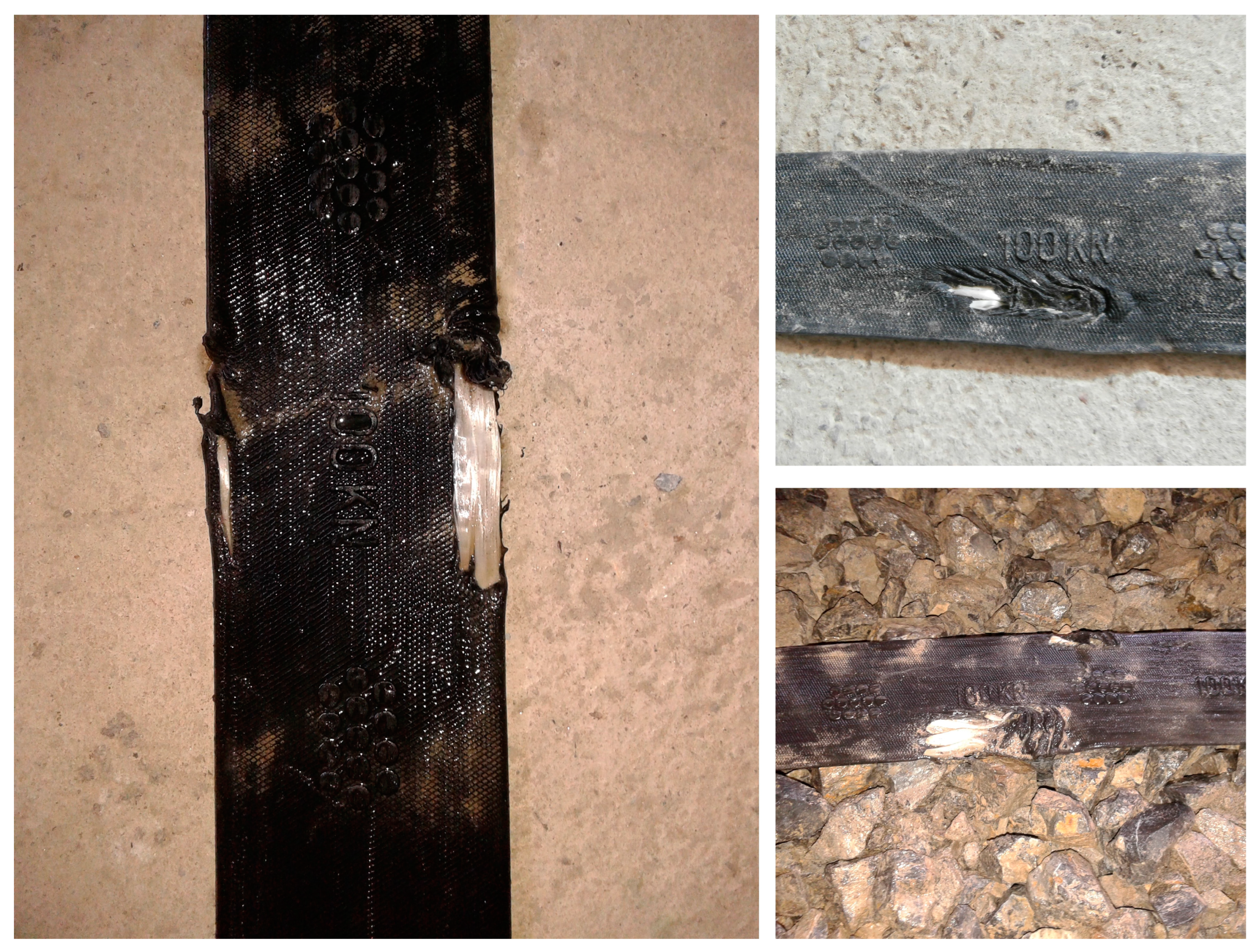
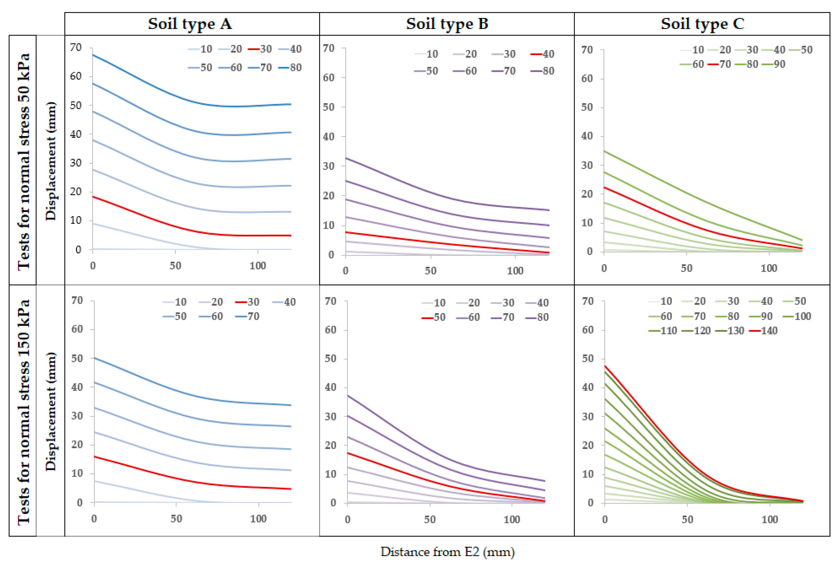
3.2. The Stress–Strain Behavior of the Strap during the Pullout Tests

The pullout tests revealed that the mobilization of the straps varied greatly depending on the grain size distribution of the backfill material and the applied normal stresses. The pullout force was measured on the piston, while displacements were monitored on the piston and at four points distributed along the length of the strap using extensometers. The first point (E1) at which displacements were measured was located at the position where the strap enters the box. This point was chosen to ensure that the fastening system that attaches the strap to the piston does not loosen. Therefore, the readings of the deformation in this segment do not represent only the deformation of the strap but rather a possible loosening of the fastening system. The second point (E2) was located inside the box, 200 mm from the sleeve. The third point (E3) was in the center part of the box, while the fourth point (E4) was 200 mm from the back end of the box. Figure 11 shows the readings of the displacements for backfill material C pulled out at the normal stress of 100 kPa. The curves represent readings recorded at every 10 mm of the piston displacement. Based on the above, the strap and the deformations of the strap can be divided into four zones and two subzones. Zone 1 represents a free part of the strap (between the piston and the E1). Subzone 2A also represents a free part of the strap (inside the sleeve, between E1 and the strap entrance at the front of the box). Subzone 2B represents part of the strap emplaced in fine sand (between the strap entrance at the front of the box and E2). The fine sand was used in this subzone between the strap and the backfill material to prevent grain pinching at the sleeve. Zone 3 represents the emplaced part of the strap in backfill material between E2 and E3. Zone 4 also represents the emplaced part of the strap in backfill material between E3 and E4.
At the beginning of the pullout test, the deformation of the strap in Zone 1 is zero. All deformations of the strap occur in Zone 2. This can be attributed that the part of the strap in contact with the surrounding material in subzone 2B takes over all the pullout force applied by the piston. As the development of the test progresses, the deformations of the strap in Zone 1 gradually increase, the deformation of the strap start in Zone 2 and finally start in Zone 3. The start of the deformation in Zone 2 and Zone 3 represents the mobilization of the strap under the applied pullout force in Zone 2 and Zone 3, respectively. E4 is placed close to the rear end of the pullout box, so the start of displacement readings on this extensometer (E4) can be considered as the point where the strap starts to displace with the entire length in the pullout box (this point is represented as a red line in Figure 11). In this case, for the backfill material C tested under the normal stress of 100 kPa, this point occurs at the displacement of the piston of 120 mm.
Figure 12 shows the readings of the displacements at extensometers placed inside the box (E2, E3, and E4) for backfill material A, B, and C pulled out at the normal stresses of 50 and 150 kPa. The readings are also recorded at every 10 mm of piston displacement. The grain size distribution significantly affects the stress–deformation behavior of the straps in these cases. For a normal stress of 150 kPa, the entire length of the strap is mobilized at a piston displacement of 30 mm for material A, 50 mm for material B, and 140 mm for material C. The value of the normal stress influences the stress–deformation behavior of the strap only for backfill material C. In that case, at 50 kPa, 100 kPa, and 150 kPa, the entire strap is mobilized at a displacement of 70, 120, and 140 mm, respectively. When using backfill material A, the entire length of the strap is mobilized at a displacement of 30 mm at both 50 kPa and 150 kPa of normal stress. In the case of backfill material B, the difference is slightly larger. At 50 kPa, the entire strap is mobilized at a displacement of 40 mm, while at 150 kPa, the entire strap is activated at a displacement of 50 mm. It follows that, in the case of a uniformly graded backfill material, the strap behaves like a rigid reinforcement, as shown by the nearly linear displacement curves. In the case of a well-graded backfill material, the elongation of the strap occurs. It can be seen that the deformation of the strap end clearly lags behind that of the beginning of the strap. It was also found that the effect of strap elongation increases with the increase in the normal stress and the coefficient of uniformity of the material.

3.3. The Influence of Strap Interaction on the Pullout Resistance

The pullout tests with two straps were carried out for two separated straps (horizontal distance of 200 mm) and for two closely spaced straps. The material used for the tests was well-graded crushed stone aggregate C, and the tests were performed only under a normal stress of 50 kPa. A similar study with two separate straps was conducted by Abdelouhab et al. [32] using sand or gravel as the backfill material. The authors concluded that the higher friction interaction coefficients with two parallel straps are a consequence of the arcing effect or dilatancy between the two straps and, thus, an increase in the stress area around the strap inclusion. To reduce or eliminate the effect of arching (or the influence of one strap on the other) when two separated straps are pulled out, a specially equipped fastening system was developed. This fastening system enabled the emplacement of two straps on a horizontal distance of 200 mm between the straps (twice the strap width). In this way, the impact of the strap fastening system is reduced, so it can be assumed that the measured pullout forces are results only of the mechanism of interaction between straps and soil.
The experiments with two separate straps and two closely spaced straps allowed the determination of the influence of lateral friction on the friction interaction coefficient. Two tests were carried out: one with separated straps and one with closely spaced straps. The test results showed that the pullout force is higher in the case of two separated straps. The results of the pullout with one strap (measured pullout force 31.72 kN) and two closely spaced straps (measured pullout force 59.13 kN) showed that the pullout force for two closely spaced straps is 1.87 times higher than the pullout force for one strap. The comparison between two separated straps (measured pullout force 70.09 kN) and one strap showed that the pullout force for two separated straps was 2.24 times higher. These results indicate that the lateral friction on the strap has a significant influence on the pullout force. The measured pullout force can be divided per strap. In this case, pullout force per strap is 31.72 kN, 29.57 kN, and 35.45 kN for one strap, two closely spaced straps, and two separated straps, respectively. According to Equation (4), the pullout force per strap for two closely spaced straps is 6.8% lower compared to one strap. The pullout force per strap for two separated straps is 11.8% higher compared to one strap. These results indicate the presence of significant lateral friction on the side of the strap. Calculating the lateral friction force according to Equation (4) gives a lateral friction force of 5.86 kN, and calculating it according to Equation (5) gives a lateral friction force of 4.31 kN. The mean value of the lateral friction force is than 5.1 kN, which results in the contribution of lateral friction force in the pullout force of 16.1%.

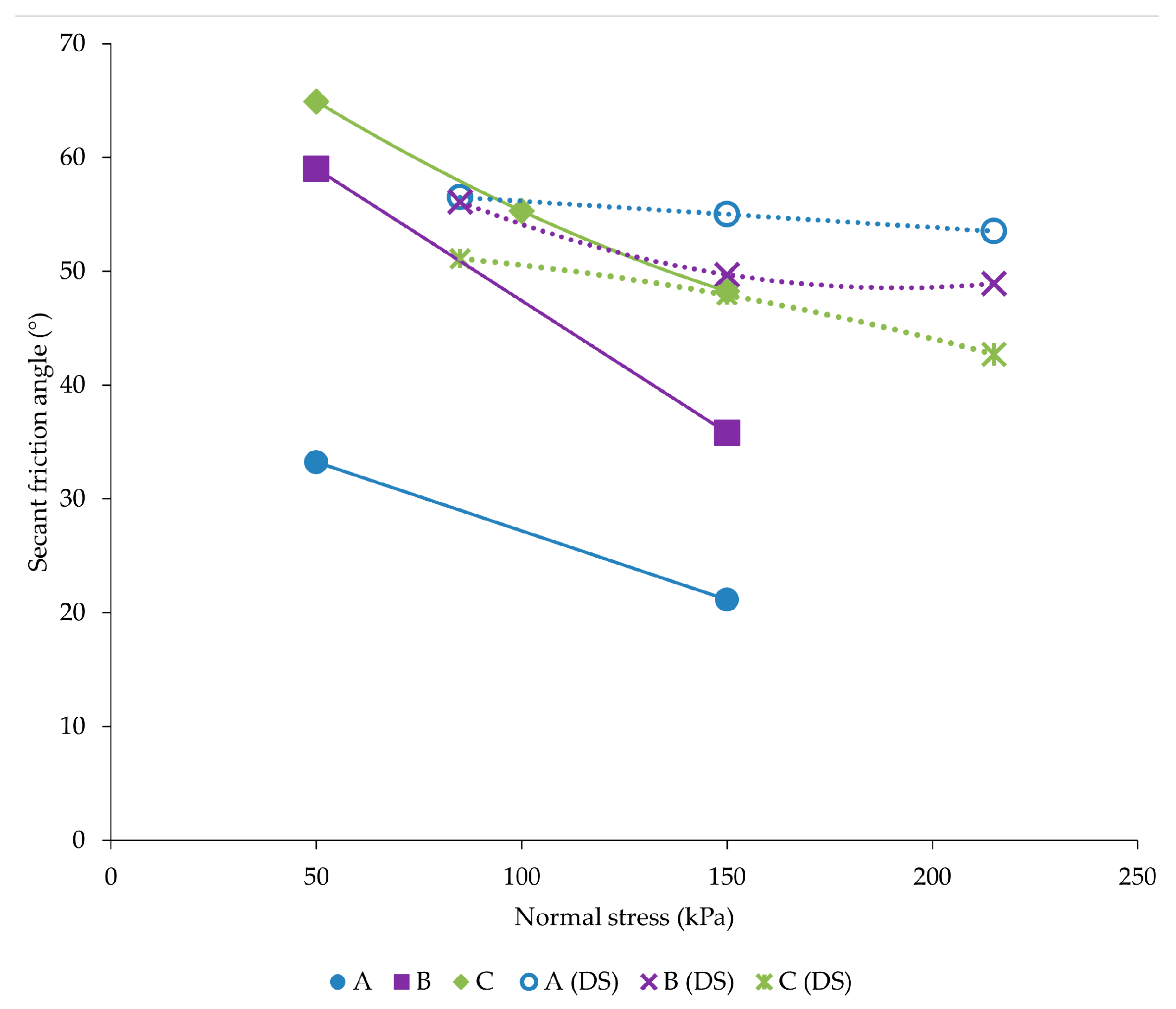
3.4. The Calculated Values of the Friction Interaction Coefficient

The pullout tests with one strap were performed to determine the influence of normal stress and grain size distribution on the friction interaction coefficient. From the performed pullout tests, it is found that the friction interaction coefficient at higher normal stress (150 kPa) is 1.5 to 2.0 times lower than at lower normal stress (50 kPa). In the case of the influence of the grain size distribution on the friction interaction coefficient at the same normal stress of 50 kPa, the friction interaction coefficient for backfill material C is 3.2 times higher than the friction interaction coefficient for backfill material A. At a higher normal stress (150 kPa), the difference is smaller. The friction interaction coefficient for backfill material C is 2.8 times higher than the friction interaction coefficient for backfill material B. The comparison of the friction interaction coefficient when pulling out one strap, two separated straps (CS), and two closely spaced straps (CC) shows that the maximum friction interaction coefficient is obtained for two separated straps, followed by for one strap, and, finally, for two closely spaced straps. The values of the friction interaction coefficient from all tests are shown in Figure 13.
From the experimental results, it can be concluded that the grain size distribution has a significant effect on the friction interaction coefficient and that the relationship recommended by AASHTO [38] for the friction interaction coefficient calculation, where the friction interaction coefficient can be determined by Expression 3 (with a maximum friction angle of 36 degree), is suitable for crushed stone with a Cu < 4 as backfill material. For backfill material B, which meets the Cu > 4 criterion for greater depths in walls, a friction interaction coefficient of 0.79 is obtained experimentally, which is more than the coefficient that would be determined using Expression 3. For the backfill material C, the friction interaction coefficient would be significantly underestimated if using Expression 3. Therefore, it can be concluded that, when the maximum recommended friction angle of 36 degrees is taken in the calculation according to Expression 3, the interaction coefficients for crushed stone with Cu > 4 are significantly underestimated. Considering the fact that the straps are installed in the wall in such a way that two straps are usually located at a small distance from each other, the difference between the recommended values for the interaction coefficient and the measured values is even greater. Figure 13 also shows the values from the literature for the friction interaction coefficients for geosynthetic straps, where it can be seen that the friction interaction coefficients for backfill material A are below the line, while the friction interaction coefficients for backfill material B and C are well above the lines. A comparison with the friction interaction coefficients determined in other studies is shown in Figure 13.

4. Conclusions

This paper presents the influence of grain size distribution with different coefficients of non-uniformity on the mechanism of interaction between geosynthetic straps and crushed stone backfill. The main conclusions that can be drawn from this work are the following:
When crushed stone with larger grain diameters is used in reinforced soil structures, it is necessary to meet the AASHTO [38] requirement for uniformity coefficient Cu > 4. If the backfill material used had a uniformity coefficient of less than 4, the friction interaction coefficient was found to be much lower than the values used in practice.
Crushed stone, especially with larger grain diameters, has very high values for the internal friction angle. The use of the expression to determine the friction interaction coefficient for depths greater than 6 m, which corresponds to 2/3 of the tangents of the internal friction angle of the backfill material, should be used with caution. For the crushed stone aggregate with Cu < 4, it is justified to take a maximum friction angle not greater than 36 degrees. For the well-compacted crushed stone aggregate with Cu > 4, the friction interaction coefficient calculated by Expression 3 underestimates the friction interaction coefficient for polyester strap and crushed stone.
The secant friction angles from the pullout tests and the secant friction angles from the direct shear tests have shown that the shear strength parameters of the tested backfill materials behave inversely so that a larger secant friction angle of the backfill does not mean that it achieves a larger pullout resistance.
The tests showed that the highest interaction coefficient was obtained with the backfill material that had the highest uniformity coefficient and highest backfill density. This shows that the grain size distribution and the density of the backfill material has a significant influence on the behavior of the strap and that it is important that the strap is in contact with as many grains as possible.
To mobilize the entire strap, the largest deformations are required for a well-graded crushed stone. The grain size distribution has the greatest influence on the stress–deformation behavior of the straps. For the strap length of 1.25 m with well-graded material C, pullout tests under a normal stress of 50 kPa mobilize a 50% smaller length of the strap compared to material A. At a normal stress of 150 kPa, this difference is even greater. The value of normal stress affects the stress–deformation behavior of the strap only for well-graded backfill material. For uniformly graded crushed stone, the entire length of the strap is mobilized at similar horizontal deformations, which are smaller than for well-graded backfill material.
The phenomenon of lateral friction acting on the sides of the strap was demonstrated. In this study, the contribution of the lateral friction force in the pullout force was 16.1%. For the two closely spaced strap, the pullout forces per strap are 6.8% lower than the pullout forces for one strap. This result is important for the design of MSEWs since the lower pullout resistance must be taken into account for parts in construction where two straps are laid side by side.
Tests have shown that, if the backfill material is uniformly graded, damage to the strap occurs during installation and testing, while if the backfill material is well graded, such damage is not noticed.
During the pullout tests of the geosynthetic straps, the grain size distribution of backfill material was shown to have a significant effect on the resistance of the strap to pulling out, as well as on the deformation of the strap itself during testing. For future testing, it would be beneficial to carry out tests with two separate strips at different strip spacings and to determine the zone of the backfill material that is mobilized during the pullout. The influence of roundness would also need to be investigated for coarse-grained materials. Accordingly, studies should be conducted for the same or similar backfill material grain size with round grains to determine the effect of grain angularity on the pullout mechanism. Further tests should also be directed toward additional investigations of the effect of lateral friction, which could be determined for various strap widths and thicknesses.

Author Contributions

K.H. and K.M. conceived of the present idea and planned the experiments. K.M. carried out the experiments, and K.H. performed the analysis of the test results. K.H. and D.D. prepared the original manuscript. I.H. contributed to the analysis and the validation of the results. All authors discussed the results and contributed to the final manuscript. All authors have read and agreed to the published version of the manuscript.

Funding

This research was funded by: “Application of numerical calculations in the analysis of the stability of underground rooms.” of the University of Zagreb Internal Project. No. 113400083.

Institutional Review Board Statement

Not applicable.

Informed Consent Statement

Not applicable.

Data Availability Statement

The data supporting this study are included within the article.

Acknowledgments

We would like to express our sincere gratitude to Predrag Kvasnička and Mensur Mulabdić for guidance and support throughout the research process. We also wish to thank the company Radlovac d.d. for the donation of the crushed stone aggregate and to the Faculty of Civil Engineering and Architecture Osijek for making available to us their pullout test device.

Conflicts of Interest

The authors declare no conflict of interest.

References

  1. Samtani, N.C.; Nowatzki, E.A. Mechanically Stabilizes Earth (MSE) Wall Fills—A Framework for Use of Local Available Sustainable Resources (LASAR); Publication No. FHWA-HIN-21-002; U.S. Department of Transportation, Federal Highway Administration: Washington, DC, USA, 2021.
  2. Herceg, V.; Klanfar, M.; Herceg, K.; Domitrović, D. Specific energy consumption of material handling by excavator in the quarrying of crushed stone. Rud.-Geol.-Naft. Zb. 2023, 38, 83–92. [Google Scholar] [CrossRef]
  3. Durukan, Z.; Tezcan, S.S. Cost analysis of reinforced soil walls. Geotext. Geomembr. 1992, 11, 29–43. [Google Scholar] [CrossRef]
  4. Singh, H.; Akhtar, S. A review on economical analysis of reinforced earth wall with different types of reinforcing materials. Int. J. Latest Technol. Eng. Manag. Appl. Sci. 2015, 4, 68–74. [Google Scholar]
  5. Basudhar, P.K.; Vashistha, A.; Deb, K.; Dey, A. Cost Optimization of Reinforced Earth Walls. Geotech. Geol. Eng. 2008, 26, 1–12. [Google Scholar] [CrossRef]
  6. AASHTO. Standard Specification for Highway Bridges, 17th ed.; AASHTO: Washington, DC, USA, 2002. [Google Scholar]
  7. FHWA-NHI-10-024: Design and Construction of Mechanically Stabilezed Earth Walls and Reinforced Soils Slope—Volume I; U.S. Departement of Transoirtation, Federal Highway Administration: Washington, DC, USA, 2009.
  8. Weldu, M.T. Pullout Resistance of MSE Wall Steel Strap Reinforcement in Uniform Aggregate. Master’s Thesis, University of Kansas, Lawrence, KS, USA, 24 November 2015. [Google Scholar]
  9. Bergado, D.T.; Chai, J.-C. Pullout force/displacement relationship of extensible grid reinforcements. Geotext. Geomembr. 1994, 13, 295–316. [Google Scholar] [CrossRef]
  10. Palmeira, E.M. Bearing force mobilisation in pull-out tests on geogrids. Geotext. Geomembr. 2004, 22, 481–509. [Google Scholar] [CrossRef]
  11. Suits, L.D.; Sheahan, T.; Lee, H.-S.; Bobet, A. Laboratory Evaluation of Pullout Capacity of Reinforced Silty Sands in Drained and Undrained Conditions. Geotech. Test. J. 2005, 28. [Google Scholar] [CrossRef]
  12. Minažek, K. Model Testing of Geogrid-Soil Interaction. Ph.D. Thesis, University of Zagreb, Faculty of Civil Engineering, Zagreb, Croatia, 20 December 2010. [Google Scholar]
  13. Lawson, W.; Jayawickrama, P.; Wood, T.; Surles, J. Pullout Resistance Factors for Steel Reinforcements Used in TxDOT MSE Walls. In Proceedings of the Geo-Congress 2013: Stability and Performance of Slopes and Embankments III, San Diego, CA, USA, 3–7 March 2013; ASCE: Reston, VA, USA, 2013; pp. 44–53. [Google Scholar] [CrossRef]
  14. Sukmak, K.; Sukmak, P.; Horpibulsuk, S.; Han, J.; Shen, S.-L.; Arulrajah, A. Effect of fine content on the pullout resistance mechanism of bearing reinforcement embedded in cohesive–frictional soils. Geotext. Geomembr. 2015, 43, 107–117. [Google Scholar] [CrossRef]
  15. Park, K.; Kim, D.; Park, J.; Na, H. The Determination of Pullout Parameters for Sand with a Geogrid. Appl. Sci. 2020, 11, 355. [Google Scholar] [CrossRef]
  16. Alfaro, M.C.; Hayashi, S.; Miura, N.; Watanabe, K. Pullout Interaction Mechanism of Geogrid Strip Reinforcement. Geosynth. Int. 1995, 2, 679–698. [Google Scholar] [CrossRef]
  17. Ochiai, H.; Otani, J.; Hayashic, S.; Hirai, T. The pull-out resistance of geogrids in reinforced soil. Geotext. Geomembr. 1996, 14, 19–42. [Google Scholar] [CrossRef]
  18. Moraci, N.; Gioffrè, D. A simple method to evaluate the pullout resistance of extruded geogrids embedded in a compacted granular soil. Geotext. Geomembr. 2006, 24, 116–128. [Google Scholar] [CrossRef]
  19. Palmeira, E.M. Soil–geosynthetic interaction: Modelling and analysis. Geotext. Geomembr. 2009, 27, 368–390. [Google Scholar] [CrossRef]
  20. Ezzein, F.M.; Bathurst, R.J. A new approach to evaluate soil-geosynthetic interaction using a novel pullout test apparatus and transparent granular soil. Geotext. Geomembr. 2014, 42, 246–255. [Google Scholar] [CrossRef]
  21. Lo, S. Pull-Out Resistance of Polyester Straps at Low Overburden Stress. Geosynth. Int. 1998, 5, 361–382. [Google Scholar] [CrossRef]
  22. Abdelouhab, A.; Dias, D.; Freitag, N. Physical and analytical modelling of geosynthetic strip pull-out behaviour. Geotext. Geomembr. 2010, 28, 44–53. [Google Scholar] [CrossRef]
  23. Pierozan, R.; Araujo, G.; Palmeira, E.; Romanel, C.; Zornberg, J. Interface pullout resistance of polymeric strips embedded in marginal tropical soils. Geotext. Geomembr. 2022, 50, 20–39. [Google Scholar] [CrossRef]
  24. Agarwal, A.; Ramana, G.; Datta, M.; Soni, N.K.; Satyakam, R. Pullout behaviour of polymeric strips embedded in mixed recycled aggregate (MRA) from construction & demolition (C&D) waste—Effect of type of fill and compaction. Geotext. Geomembr. 2023, 51, 405–417. [Google Scholar] [CrossRef]
  25. Lo, S.R. The influence of constrained dilatancy on pullout resistance of strap reinforcement. Geosynth. Int. 2003, 10, 47–55. [Google Scholar] [CrossRef]
  26. Sobhi, S.; Wu, J. An Interface Pullout Formula for Extensible Sheet Reinforcement. Geosynth. Int. 1996, 3, 565–582. [Google Scholar] [CrossRef]
  27. Cui, X.-Z.; Wang, Y.-L.; Liu, K.-W.; Wang, X.-Z.; Jin, Q.; Zhao, M.-L.; Cui, S.-Q. A simplified model for evaluating the hardening behaviour of sensor-enabled geobelts during pullout tests. Geotext. Geomembr. 2019, 47, 377–388. [Google Scholar] [CrossRef]
  28. Vieira, C.S.; Pereira, P.; Ferreira, F.; Lopes, M.d.L. Pullout Behaviour of Geogrids Embedded in a Recycled Construction and Demolition Material. Effects of Specimen Size and Displacement Rate. Sustainability 2020, 12, 3825. [Google Scholar] [CrossRef]
  29. Kvasnička, P.; Sorić, L.; Gradiški, K.; Marohnić, M. Mechanically stabilized earth wall—A case history. In Proceedings of the XV Danube-European Conference on Geotechnical Engineering, Vienna, Austria, 9–12 September 2014. [Google Scholar]
  30. Sorić, L.; Kvasnička, P.; Marohnić, M.; Gradiški, K.S. Trojica Reinforced Earth Wall—Back Analysis for the state Shortly after Construction. In Proceedings of the 6th Conference of Croatian Geotechnical Society, Zadar, Croatia, 17–19 October 2013. [Google Scholar]
  31. Gradiški, K.; Mulabdić, M.; Minažek, K. Selected results of determining the friction interaction coefficient between crushed stone and polyester strip. Rud.-Geol.-Naft. Zb. 2017, 32, 37–43. [Google Scholar] [CrossRef] [Green Version]
  32. Abdelouhab, A.; Dias, D.; Freitag, N. Pull-out behaviour of geosynthetic strap reinforcements in coarse fill physical and analytical modelling. In Proceedings of the GIGSA GeoAfrica 2009 Conference, Cape Town, South Africa, 2–5 September 2009. [Google Scholar]
  33. Razzazan, S.; Keshavarz, A.; Mosallanezhad, M. Large-scale pullout testing and numerical evaluation of U-shape polymeric straps. Geosynth. Int. 2019, 26, 237–250. [Google Scholar] [CrossRef]
  34. Park, J.; Hong, G. Effective Length Prediction and Pullout Design of Geosynthetic Strips Based on Pullout Resistance. Materials 2021, 14, 6151. [Google Scholar] [CrossRef] [PubMed]
  35. ASTM D6706-01 (2001); Standard Test Method for Measuring Geosynthetic Pullout Resistance in Soil. ASTM International: West Conshohocken, PA, USA, 2001.
  36. Minažek, K.; Mulabdić, M. A review of soil and reinforcement interaction testing in reinforced soil by pullout test. Građevinar 2013, 65, 235–250. [Google Scholar] [CrossRef]
  37. Schlosser, F.; Bastick, M. Reinforced Earth. In Book Foundation Engineering Handbook, 2nd ed.; Fang, H.Y., Ed.; Springer Science Bussiness Media: New York, NY, US, 1991; pp. 778–795. [Google Scholar]
  38. AASHTO. LRFD Bridge Design Specifications, 9th ed.; American Association of State Highway and Transportation Officials (AASHTO): Washington, DC, USA, 2020. [Google Scholar]
Figure 1. Scheme of the pullout box [36].
Applsci 13 08606 g001
Figure 2. Particle size distribution of the backfill material samples used in pullout tests.
Applsci 13 08606 g002
Figure 3. Geosynthetic strap cross-section.
Applsci 13 08606 g003
Figure 4. The positions of the extensometers for the test setup with one strap.
Applsci 13 08606 g004
Figure 5. The positions of the extensometers for the test setup with two straps: (a) straps with horizontal displacement of 200 mm and (b) straps positioned close to each other.
Applsci 13 08606 g005
Figure 6. The pullout curves for materials A, B, and C tested at normal stresses of 50 and 150 kPa.
Applsci 13 08606 g006
Figure 7. Damage of the straps in backfill material A.
Applsci 13 08606 g007
Figure 8. Pullout force for materials A, B, and C.
Applsci 13 08606 g008
Figure 9. Shear stresses at the strap–backfill contact obtained from pullout tests (PU).
Applsci 13 08606 g009
Figure 10. Secant friction angles for materials A, B, and C from direct shear test (DS) and secant friction angles at the strap–backfill contact from pullout tests (PU).
Applsci 13 08606 g010
Figure 11. The readings of the displacements along the strap for backfill material C pulled out at a normal stress of 100 kPa. The data were recorded at every 10 mm of piston displacement.
Applsci 13 08606 g011
Figure 12. Strap displacement readings recorded on E2 (zero on x axis), E3, and E4 for the same piston displacement for backfill material A, B, and C. The readings were recorded at every 10 mm of piston displacement.
Applsci 13 08606 g012
Figure 13. Friction interaction coefficients for different backfill materials [32].
Applsci 13 08606 g013
Table 1. A brief summary of pullout tests with geosynthetic straps.
Properties of Polymeric StrapSoil CharacteristicAuthor and Reference Number
No.SingleDoubleGap Width (mm)Strap Width, bs (mm)Strap Thickness (mm)Tensile Strength per Strap (kN)Surcharge Pressure
(kPa)
Soil TypePeak Friction Angle, φ
1 85–904–6 20–30
20-30
30-50
26–95
15–100
15–100
Well graded sandy gravel
Well-graded, gravelly sand
Well-graded sand
40
40
38
Lo [21]
250502/7–80Houston Rf sand38Abdelouhab et al. [22]
350502.547.5 Coarse soil (0–31.5 mm)
Fine sand (0.16–0.63 mm)
36
36
Abdelouhab et al. [32]
4 90510050–150Crushed stone aggregate51Gradiški et al. [31]
5 90375.420–160SP40Razzazan et al. [33]
6 401.821.65–400Sand SM–SP29.5Cui et al. [27]
7 505045012.5–50S100–L0
S75–L25
S50–L50
S0–L100
44
40
38
33
Pierozzan et al. [23]
8 405035020–80Mixed recycled aggregate
Mixed recycled aggregate
Sand from quarrying rock
Fluvial sand
53–41.5
50.1–40.5
49.5–38.7
42.1–37.6
Agarwal et al. [24]
Table 2. Properties of the samples used in the pullout tests.
Sample
PropertiesA30/60B4/60C0/60
Grain size range, D (mm)30–604–600–60
Mean grain size, D50 (mm)40.120.26.5
Uniformity coefficient, Cu (-)1.564.2511.64
Curvature coefficient, Cc (-)1.131.060.93
Range of void ratio, emin–emax (-)0.54–0.620.37–0.590.27–0.46
Friction angle, φ (°)5549.747.9
Dilatancy angle, ψ (°)2117.119.8
Table 3. Testing program.
SampleNormal Stress (kPa)StrapNo. of
Tests
LabelGrain Size (mm)
A30–6050single3
150single2
B4–6050single1
150single3
C0–6050single1
100single1
150single1
50two (200 mm apart)1
two (close)1
Disclaimer/Publisher’s Note: The statements, opinions and data contained in all publications are solely those of the individual author(s) and contributor(s) and not of MDPI and/or the editor(s). MDPI and/or the editor(s) disclaim responsibility for any injury to people or property resulting from any ideas, methods, instructions or products referred to in the content.

