Abstract
To investigate the movement characteristics of fuel within an aircraft’s fuel tank during maneuvering, this study employs numerical simulations using the Finite Pointset Method (FPM) with specific boundary conditions and excitation. The simulation results successfully capture the complex phenomena of fuel free surface fluctuations, surging, rolling, and breaking, along with the corresponding changes in the center of gravity induced by fuel movement. Throughout the aircraft’s maneuvering process, the longitudinal center of gravity experiences minimal variations, whereas the aerodynamic center of gravity exhibits significant fluctuations, reaching a range of 0.47 m. The longitudinal center of gravity consistently shifts backward with a displacement of 0.41 m. The maximum height attained by the liquid’s free surface during aircraft maneuvering measures approximately 0.22 m, reaching the upper panel’s height of the wing fuel tank, resulting in a certain level of impact on the upper panel. The maximum impact force generated during the aircraft maneuvering process amounts to 2.3 × 10⁵ pascals, with the point of action located at the junction of the transverse frame and the upper panel. The findings of this work provide support for the safe design of aircraft fuel tank systems.
1. Introduction
Maneuverability is a crucial performance characteristic of aircraft, particularly in high-performance fighter jets. The fuel tank serves as a critical component of the aircraft platform, responsible for fuel storage and transfer. During the maneuvering process, external forces exert a significant influence on the fuel inside the tank, leading to intense motion that can impact both the tank’s structural integrity and the aircraft’s flight stability. This fuel movement generates shock loads on the fuel tank, necessitating the prediction of affected areas to prevent fatigue damage. The dynamic changes occurring in the free liquid surface during fuel movement result in alterations in mass distribution and liquid level height distribution within the tank. Consequently, the fuel’s center of gravity undergoes a shift, potentially exerting adverse effects on the aircraft’s flight attitude and stability. Furthermore, as the flight range increases, the amount of fuel carried by the aircraft also rises, intensifying the impact of fuel movement on the tank wall. Therefore, studying the movement characteristics of fuel in the fuel tank under maneuvering conditions holds significant engineering significance in improving aircraft flight stability and fuel tank safety.
For the problem of free surface motion of liquids in limited space, it has attracted the attention of engineers from various countries [1,2,3]. Currently, numerical simulation methods for free surface problems mainly include the Arbitrary Lagrange Euler (ALE) method, Volume of Fluid (VOF) method, and Smoothed Particle Hydrodynamics (SPH) method. Eswaran et al. [4] used the ALE method to numerically calculate the sloshing problem of a square tank with baffles. Cao et al. [5] used the ALE method to describe the fluid large deformation motion, combined with large eddy simulation, to calculate the dynamic response of flexible container sloshing under wind load. Akyildız and Unal [6,7] used the VOF method to numerically simulate a three-dimensional rectangular liquid tank, calculating impulsive pressure and non-impulsive pressure. Among them, the Smoothed Particle Hydrodynamics (SPH) method is a grid-free calculation method proposed by Lucy [8] and Gingold [9] in 1977, which has been widely used in the field of fluid dynamics [10,11]. Colagrossi and Landrini [12] overcame the pressure noise problem in simulating free surface hydrodynamics problems using the SPH method by the means of density filtering. Colagrossi et al. [13] theoretically proved that the weakly compressible SPH method can automatically satisfy the free surface boundary conditions at the free surface, and the truncation of the kernel function at the free surface does not affect the accuracy of the free surface simulation. Celebi and Akyildiz [14] numerically studied the sloshing of rectangular liquid tanks and found that, when excited near the resonance frequency, the numerical results of wave amplitude were smaller than the experimental and theoretical values. They believed that this could be due to the unreasonable reflection of liquid viscosity effects in the numerical model, but did not conduct a detailed study on this issue.
Compared with traditional grid-based methods, the SPH method is suitable for simulating problems involving large deformations, free surfaces, moving boundaries, and deformable boundaries. It solves the problem of grid distortion caused by large deformations in traditional grid-based numerical methods when solving the problem of liquid shaking. However, the SPH method also has shortcomings or areas for improvement, such as poor calculation accuracy when particles are irregularly distributed, low algorithm stability, and incomplete boundary handling [15]. The literature [16] proposes using a finite number of particles to discretize the fluid domain, with each particle carrying physical information such as velocity and pressure, called the Finite Pointset Method (FPM). This method is an important development of the SPH method in the field of grid-free calculation. In terms of simulating the free surface, although there are relevant literature and demonstrations in different technical fields, most of them are based on traditional Smoothed Particle Hydrodynamics (SPH), Arbitrary Lagrangian–Eulerian (ALE) and dynamic mesh methods. Similar to SPH, the FPM is a grid-free approach that utilizes a collection of Lagrangian particles to represent the fluid state. FPM employs a smoothing function and its derivatives to approximate function values, making it an enhanced version of SPH. However, conventional SPH suffers from lower order accuracy in boundary regions due to its lack of first-order accuracy. Additionally, SPH is computationally expensive and is not suitable, particularly for large-scale simulations.
The movement of fuel in a fuel tank under excitation is a complex and highly nonlinear free surface phenomenon with randomness. Wang Li et al. [17] simulated the interaction between fuel and the fuel tank during unmanned aerial vehicle launch using the Arbitrary Lagrange Euler (ALE) method. Yang Shanglin et al. [18] used the finite element software ABAQUS 2018 and a traditional Volume of Fluid (VOF) method to obtain the shape changes of fuel during a semi-roll process. Yang Rui [19] simulated the fuel sloshing of a wing fuel tank under steady axis rotation using the ALE method, while Liu Fu et al. [20] used the Smoothed Particle Hydrodynamic (SPH) method to calculate the fuel movement characteristics of an auxiliary fuel tank during pitch motion. The above-mentioned studies explored the free surface problem of fuel under simple working conditions using methods such as ALE, SPH, and VOF, but did not consider the movement of fuel under complex overloads.
In this study, the FPM is employed to simulate the fuel movement characteristics of an aircraft under short-term composite acceleration excitation. The fuel tank model used in this research closely approximates the actual tank shape and takes into full consideration the influence of the internal tank structure on fuel movement. The investigation focuses on obtaining the free surface characteristics of fuel in such scenarios, with the acquired data providing support for aircraft development.
For fuel tanks with a high-liquid filling ratio, such as spacecraft propellant tanks, aircraft fuel tanks, and tanker trucks, the substantial liquid movement within a short period during motion can lead to changes in the system’s center of gravity. Consequently, this may have adverse effects on the motion trajectory or attitude of liquid-carrying systems such as spacecraft, aircraft, and tanker trucks. The research findings presented in this paper offer valuable guidance and serve as a reference for the structural design of aircraft fuel tanks, overall aircraft design, optimization of spacecraft propellant tanks, and the design of liquid-carrying ships and other related liquid-carrying systems.
2. Research Object and Numerical Method
2.1. Research Object
The object of this study is the wing fuel tank located in the wing of the aircraft, referred to as the wing tank, as shown in Figure 1. The tank has a flat shape and a wall thickness of 3 mm. The tank is equipped with baffles and related pipelines with flow holes inside, and the baffles mainly include multiple transverse frames and a longitudinal wall, dividing the tank area into multiple small compartments. The tank wall and pipelines are made of aluminum with a density of 2700 kg/m3. The tank is not completely filled with liquid fuel, with a fill ratio of 85%. The density of the fuel is 780 kg/m3.
Figure 1.
Physical model of the fuel tank. (a) The shape of the fuel tank; (b) Internal structure; (c) Flow holes.
To facilitate accurate capturing of the free liquid surface height and impact pressure at different locations, eight virtual sensors are installed in the tank to measure the fuel immersion height, i.e., the corresponding liquid surface height at each position, and sense the impact pressure of the fuel. The position coordinate information of each sensor in the tank is shown in Table 1, where the X coordinate is based on the origin of the aircraft nose, the Y coordinate is based on the aircraft horizontal reference plane, and the Z coordinate is based on the aircraft symmetry plane with units all in meters.

Table 1.
Virtual Sensor Number and Location.
2.2. Numerical Calculation Method and Validation
The motion of fuel can be described using the Navier–Stokes (N–S) equations and the incompressibility condition. The governing equations of a free surface incompressible flow in Lagrangian form are provided by the following PDEs.
where is the fluid density, is the pressure, is the kinematic viscosity. As FPM does not require the support of grid and therefore fluid values are known at discrete “interpolation” points, the Based on Kernel Function Interpolation, a correspondence between discrete particles and continuous physical fields, can be established, achieving the discretization of the fluid-fuel-flow physical field.
This article uses the meshless method with a finite set of points. The FPM generates discrete particle points using a nodal distribution approach and solves algebraic equations discretely. This method determines the computed fluid domain based on the characteristics of the set model and generates computational nodes within the fluid domain. As the computational fluid domain may change over time, the computational fluid domain at a certain moment is defined as , with its boundary denoted as . A series of computational particle points is generated within the computational domain, including interior points and boundary points .
Starting from the boundaries and advancing simultaneously into the computational domain, the direction of advancement is along the normal direction of the boundary points. When generating particle points, the inner and outer boundaries of the computational domain are numbered and their advancing directions are specified. During the advancement process, particle points continuously search for points generated by different numbered boundaries. If the distance between two points is less than the influence domain radius h, the generation of points in this direction is considered to have satisfied the calculation requirements. This method has good fitting effects for various boundaries and can reduce the number of particle points and improve computational efficiency by using ratio-based generation methods.
In numerical simulations, it is common to approximate the values of a function and include its derivatives at a specific point. At a nearby point , we can perform a Taylor series expansion and retain the first-order derivative, resulting in a smooth function for point , which can be described by the following expression:
here, is the dimension index from x to z, and represents the remainder of the Taylor expansion. can be defined as
By multiplying both sides of the equation by the function and integrating it in space , we obtain the following equation:
An assumption made here is that point is strongly influenced by nearby points, while distant points have a weaker influence on it. Thus, a function can be defined as , where h is a length that characterizes the impact space distance.
The density of the point set within the computational domain affects the distribution layout of the points and the size of the smoothing length. The density of any point can be obtained by integrating the density of the neighboring particles around that point:
The spatial distribution of the point set within the computational domain dynamically changes over time, and the number and positions of the points supported by point are reiterated at each time step. During the calculation, other points within the supporting domain of point exert an effect on it through a smoothing function, which is used for the integration interpolation of the central point .
To verify the credibility of the FPM in accurately simulating fuel movement, a simulation was conducted to analyze the movement of a simple elongated cylindrical fuel tank under excitation. The simulation results were then compared with experimental findings presented in reference [21], as depicted in Figure 2. The comparison demonstrates a close agreement between the shape of the free liquid surface predicted by the FPM and the experimental results. Under excitation, the free liquid surface exhibits a rightward movement and is constrained by the right boundary, resulting in a smooth surface with a higher left side and a lower right side. As the excitation continues, the liquid on the right side experiences a certain degree of compression and flips along the upper boundary towards the left. This flipping process causes collisions and localized disruptions at the edge of the free liquid surface, leading to the formation of splashing. Based on the excellent agreement between the simulation results and the reference experimental data, this method can be applied in engineering computational analysis.
Figure 2.
Comparison of free surface shapes between experimental (left) and numerical simulation (right). (a) The surging process; (b) Flip and shatter.
2.3. Boundary Conditions
When fuel moves within a fuel tank, it occupies both the fluid domain and the solid domain of the fuel tank structure. As a result, a boundary exists between the liquid phase and the solid phase. At this boundary, the fuel is unable to leave the fuel tank wall or penetrate through it. Assuming negligible influence from fuel surface tension and air pressure within the fuel tank on the free liquid surface, the boundary conditions for the free liquid surface are as follows:
Among them, is the normal velocity of the free liquid surface, is the tangential velocity of the free liquid surface, and are the pressures on the liquid side and air side of the free liquid surface, respectively. In terms of boundary treatment, for the internal boundary of the fuel tank, it is defined as a no-slip wall surface. The particle positions on this boundary remain fixed, so the velocity of particles on the boundary is zero. The free surface is represented by free boundary particles, and at the beginning of each time step, it is necessary to traverse and detect the free surface particles.
2.4. External Excitation
During actual aircraft maneuvering, it is subjected to various excitation factors such as lateral, heading, and normal accelerations, as well as pitch, roll, and other factors. Here, we focus on the influence of heading acceleration and pitch angle variation on fuel movement, that is, the fuel in the tank is simultaneously affected by heading acceleration and pitch excitation. Figure 3 shows the heading acceleration and pitch angle variation during the aircraft maneuvering process. The overload process includes the loading and unloading phases, both of which are completed in a short time. The 0–1.5 s period is the loading phase, during which the acceleration rapidly increases to nearly 35 m/s2 and the flight speed increases rapidly. After 1.5 s, it enters the unloading phase, during which the acceleration decreases at a relatively low rate to 32 m/s2, then rapidly decreases to 23 m/s2, and then sharply decreases to nearly 5 m/s2.
Figure 3.
Curves of heading acceleration and pitch angle variation during the maneuver process.
3. Results and Analysis
3.1. Fuel Center of Gravity Variation
Figure 4 illustrates the changes in the fuel center of gravity in the heading, pitch, and roll directions during the maneuver process. Initially, as the maneuver commences, the acceleration increases abruptly, causing the fuel inside the tank to accumulate in the opposite direction of flight. Consequently, the heading fuel center of gravity undergoes a rapid aft movement. However, after 1.5 s, although the acceleration and pitch angle continue to change, most of the fuel has already filled the rear section of the tank due to its limited volume. As a result, the variation in the heading fuel center of gravity becomes less significant.
Figure 4.
Fuel center of gravity in the heading, pitch, and roll directions during the maneuver process.
Simultaneously, as the acceleration increases rapidly and the fuel flow is obstructed by the baffle within the tank, the fuel gathers and flows through the flow holes on the baffle towards the wingtip direction. This results in a gradual increase in the roll fuel center of gravity. Nonetheless, the amplitude of variation in the roll fuel center of gravity remains relatively small.
During the middle stage of the maneuver, the fuel rapidly accumulates towards the tail of the aircraft, leading to a rapid increase in the vertical fuel center of gravity. Due to the relatively narrow dimensions of the flat fuel tank and the inertia of fuel motion, a portion of the accumulated fuel will move towards the front of the aircraft along the top of the tank. Under the influence of gravity, this portion of fuel gradually descends to the bottom of the fuel tank. Throughout the maneuver process, the fuel inside the tank repeatedly undergoes movement and detachment, resulting in fluctuations in the vertical fuel center of gravity.
3.2. Free Liquid Level Analysis
During the maneuvering process, the fluctuations of the fuel free liquid levels monitored by eight sensors are shown in Figure 5. Overall, liquid-level sensors 1–4 detected a relatively calm liquid level, while the liquid level at the location of sensors 5–8 experienced more violent surges and back-and-forth oscillations. The fuel free liquid level motion characteristics at different sensor locations are listed in Table 2.
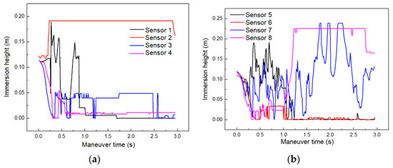
Figure 5.
Graph of the liquid level change monitored by the sensors. (a) Sensor 1–4 data; (b) Sensor 5–8 data.
Table 2.
Free liquid level characteristics at sensor locations.
3.3. Analysis of Fuel Impact Force
Figure 6 shows the changes in fuel impact pressure monitored by the sensors during the aircraft maneuvering process. It can be seen that the pressure values at the positions of sensors 1, 3, 4, 5, and 6 are relatively stable, indicating that, although there is fluctuation in the liquid level at these positions, the change in impact force is not significant. The pressure oscillation situation monitored by sensors 2, 7, and 8 is more complex. The three pressure curves monitored by sensors 2, 7, and 8 all have multiple peaks, which further indicates the existence of complex free surface phenomena at positions 2, 7, and 8. Although the times when these peaks occur are different, the overall trend is that they gradually decrease with damping.
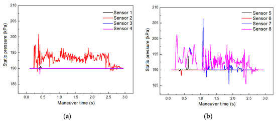
Figure 6.
Shock pressure change curve monitored by sensors. (a) Sensor 1–4 data; (b) Sensor 5–8 data.
Figure 7 presents the fuel pressure field at a typical moment during aircraft maneuvering. At the onset of the maneuver, the aircraft experiences rapid yaw acceleration, causing the fuel to shift towards the rear of the aircraft. This movement creates a phenomenon known as “water leap” or “traveling wave”, which generates impact pressure on the internal baffles and fuel tank wall panels. The presence of internal crossbeams and longitudinal walls increases the damping effect on fuel motion, impeding large-scale fuel displacement. Furthermore, the connecting holes on the baffles introduce flow resistance, dissipating the kinetic energy induced by acceleration and reducing the impact force exerted by the fuel on the fuel tank wall panels during motion. In localized areas of high pressure, such as the circular region indicating the intersection of the rear crossbeam and upper wall panel, the maximum fuel pressure reaches approximately 2.3 × 10⁵ Pa. At t = 1.5 s, the aircraft acceleration reaches its peak, resulting in the highest impact pressure observed, primarily concentrated on the rear wall panel and the right-side panel of the fuel tank. Subsequently, as the yaw acceleration of the aircraft gradually decreases, the fuel surges towards the flight direction due to inertia, leading to a more uniform stress distribution on the fuel tank wall panels.
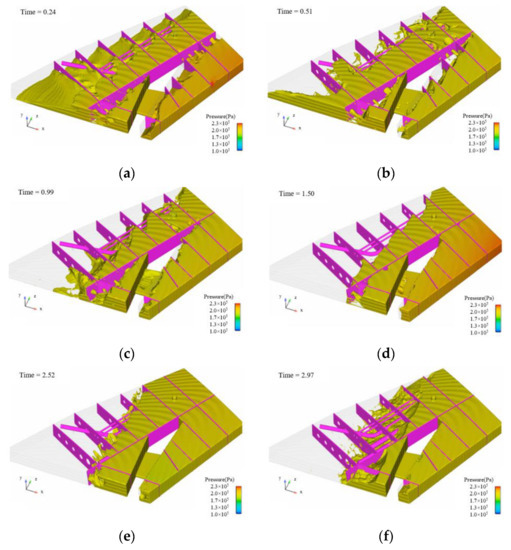
Figure 7.
Variation of fuel pressure field in the fuel tank. (a) t = 0.24 s; (b) t = 0.51 s; (c) t = 0.99 s; (d) t = 1.50 s; (e) t = 2.52 s; (f) t = 2.97 s.
3.4. Analysis of Fuel Velocity Field Characteristics
Figure 8 illustrates a segment of the speed field for the fuel free surface during the maneuvering process, depicting the transition from relative calmness to significant motion. In general, the flow field within the fuel tank exhibits turbulence, and as the fuel moves, it impacts the upper wall of the tank, resulting in a phenomenon known as “sloshing”. The free surface appears as a steep slope for a certain duration. During the initial stage of the maneuver, the fuel tends to gather and move backward. The combined effect of acceleration and pitch coupling, along with inertia, leads to significant stratification of the free surface, and the fuel velocity rapidly decreases at the flow-through holes of the transverse bulkhead and longitudinal walls. Temporal variations of fuel motion characteristics inside the tank are provided in Table 3.
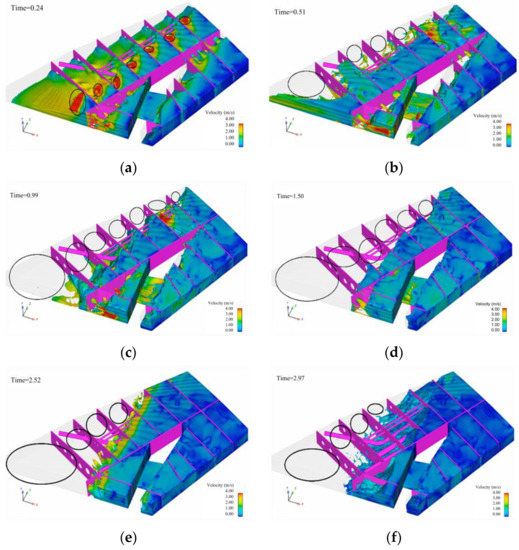
Figure 8.
Variation of fuel velocity field in the fuel tank. (a) t = 0.24 s; (b) t = 0.51 s; (c) t = 0.99 s; (d) t = 1.50 s; (e) t = 2.52 s; (f) t = 2.97 s.
Table 3.
Temporal variations of fuel motion characteristics inside the tank.
4. Conclusions
Based on simulation analysis of the fuel motion characteristics of a typical flat fuel tank during aircraft maneuvering, the following conclusions are drawn: the simulation reveals complex phenomena such as fluctuation, surge, rolling, and fragmentation of the free liquid surface of the fuel, as well as the resulting shift in the fuel center of gravity. During the maneuvering process of the aircraft, there is little change in the longitudinal center of gravity, but the aerodynamic center of gravity shows significant fluctuations, with a range reaching 0.47 m. The longitudinal center of gravity continues to move backward with a displacement of 0.41 m. The maximum height of the free surface of the liquid during aircraft maneuvering is approximately 0.22 m, reaching the height of the upper panel of the wing fuel tank, resulting in a certain impact on the upper panel. The maximum impact force generated during the aircraft maneuvering process is 2.3 × 10⁵ pascals, with the action location at the junction of the transverse frame and the upper panel. This data provides a reference for the design of the tank’s strength. The findings of this study provide support for the safe design of aircraft fuel tank systems.
The innovations of the paper are as follows:
- (1)
- Compared to other studies related to the free surface of fluids, the object of this paper is not an idealized and simplified model, but an aircraft wing fuel tank model that encompasses all structural elements. The fuel tank structure considered here includes not only the surrounding walls but also internal transverse frames, longitudinal walls, and flow holes. These structures are carefully designed according to the fuel tank design standards. The presented results reflect the comprehensive damping effect of the fuel tank structure on fuel motion, thereby providing a more realistic representation of the fuel’s movement characteristics during aircraft maneuvering.
- (2)
- Compared with our previous work [22], the flow characteristics of fuel in a flat tank are different from those of an approximate cube tank, and the size and shape of the movement space of the fuel have a significant influence on the movement of the free liquid level.
This study only analyzes the influence of aircraft heading acceleration and pitch angle on fuel motion characteristics. However, actual maneuvering processes may also include parameters such as roll acceleration and angular acceleration, which affect the motion of fuel within the fuel tank. Therefore, future research will consider the effects of roll acceleration and angular acceleration, comprehensively analyzing the role of various excitation factors on fuel motion characteristics.
Author Contributions
Conceptualization, Y.W. and S.L.; methodology, Y.W.; software, Y.W.; validation, Y.W.; formal analysis, Y.W. and C.R.; resources, Z.L.; writing—original draft preparation, Y.W.; writing—review and editing, C.R.; visualization, C.R.; supervision, S.L.; project administration, Z.L.; funding acquisition, S.L. All authors have read and agreed to the published version of the manuscript.
Funding
This research was funded by Civil Aircraft Scientific Research Project of the Ministry of Industry and Information Technology (BB2320000048, DD2320009001), the Fundamental Research Funds for the Central Universities under Grant No. WK2320000046, WK2320000049.
Institutional Review Board Statement
Not applicable.
Informed Consent Statement
Not applicable.
Data Availability Statement
Not applicable.
Acknowledgments
We thank the Supercomputing Center of the University of Science and Technology of China for providing the computing resources and guidance on computational methods.
Conflicts of Interest
The authors declare no conflict of interest.
References
- Zienkiewicz, O.C.; Taylor, R.L.; Nithiarasu, P. The Finite Element Method for Fluid Dynamics, 7th ed.; Butterworth-Heinemann: Oxford, UK, 2013. [Google Scholar]
- Moukalled, F.; Mangani, L.; Darwish, M. The Finite Volume Method in Computational Fluid Dynamics: An Advanced Introduction with OpenFOAM and matlab. In Fluid Mechanics and Its Applications, 1st ed.; Springer: New York, NY, USA, 2015; Volume 113. [Google Scholar]
- Cruchaga, M.; Battaglia, L.; Storti, M.; D’Elia, J. Numerical modeling and experimental validation of free surface flow problems, Arch. Comput. Methods Eng. 2016, 23, 139–169. [Google Scholar] [CrossRef]
- Eswaran, M.; Saha, U.; Maity, D. Effect of baffles on a partially filled cubic tank: Numerical simulation and experimental validation. Comput. Struct. 2009, 87, 198–205. [Google Scholar] [CrossRef]
- Yuan, C.; Wang, P.; Jin, X. Dynamic analysis of flexible container under wind actions by ALE finite-element method. J. Wind Eng. Ind. Aerod. 2010, 98, 881–887. [Google Scholar] [CrossRef]
- Akyildiz, H.; Unal, N.E. Sloshing in a three-dimensional rectangular tank: Numerical simulation and experimental validation. Ocean Eng. 2006, 33, 2135–2149. [Google Scholar] [CrossRef]
- Akyildiz, H.; Unal, E. Experimental investigation of pressure distribution on a rectangular tank due to the liquid sloshing. Ocean Eng. 2005, 32, 1503–1516. [Google Scholar] [CrossRef]
- Lucy, L.B. A numerical approach to testing of the fission hypothesis. Astron. J. 1977, 82, 1013–1024. [Google Scholar] [CrossRef]
- Gingold, R.A.; Monaghan, J.J. Smoothed particle hydrodynamics: Theory and application to no-spherical stars. Mon. Not. R. Astron. Soc. 1977, 181, 375–398. [Google Scholar] [CrossRef]
- Yang, X.F.; Peng, S.L.; Liu, M.B. A new kernel function for SPH with applications to free surface flows. Appl. Math. Model. 2014, 38, 3822–3833. [Google Scholar] [CrossRef]
- Feng, D.L.; Liu, M.B.; Li, H.Q.; Liu, G.R. Smoothed particle hydrodynamics modeling of linear shaped charge with jet formation and penetration effects. Comput. Fluids 2013, 86, 77–85. [Google Scholar] [CrossRef]
- Colagrossi, A.; Landrini, M. Numerical simulation of interfacial flows by smoothed particle hydrodynamics. J. Comput. Phys. 2003, 191, 448–475. [Google Scholar] [CrossRef]
- Colagrossi, A.; Antuono, M.; Le Touzé, D. Theoretical considerations on the free-surface role in the smoothed-particle-hydrodynamics model. Phys. Rev. E 2009, 79, 056701. [Google Scholar] [CrossRef] [PubMed]
- Celebi, M.S.; Akyildiz, H. Nonlinear modeling of liquid sloshing in a moving rectangular tank. Ocean Eng. 2002, 29, 1527–1553. [Google Scholar] [CrossRef]
- Liu, M.-B.; Zong, Z.; Chang, J.-Z. Developments and applications of smoothed particle hydrodynamics. Adv. Mech. 2011, 41, 217–234. [Google Scholar]
- Onate, E.; Idelsohn, S.; Zienkiewicz, O.; Taylor, R. A finite point method in computational mechanics: Applications to convective transport and fluid flow. Int. J. Numer. Methods Eng. 1996, 39, 3839–3866. [Google Scholar] [CrossRef]
- Wang, L.; Xie, H.; Zhang, L. Analysis of fuel sloshing in UAV launching process. Aeronaut. Sci. Technol. 2016, 27, 36–40. (In Chinese) [Google Scholar]
- Yang, S.L.; Chen, X.F.; Du, F.X. Coupling Dynamics Analysis of Aircraft Fuel Tank Sloshing Fluid and Solid under Maneuvering Behavior. J. Aeronaut. 2019, 40, 13. [Google Scholar]
- Yang, R. Research of Fuel Sloshing in Aircraft Integral Tanks by the ALE Finite Element Method. Master’s Thesis, Harbin Institute of Technology, Harbin, China, 2016. (In Chinese). [Google Scholar]
- Yuan, X.F. Research of Fuel Sloshing in Aircraft Wing Tank Based on VOF Method and Sloshing Suppression. Master’s Thesis, Harbin Institute of Technology, Harbin, China, 2016. (In Chinese). [Google Scholar]
- Liu, G.; Lin, Y.; Guan, G. Experimental study of sloshing pattern on LNG independent C type tank. J. Dalian Univ. Technol. 2017, 57, 467–475. (In Chinese) [Google Scholar]
- Li, Z.H.; Wang, Y.M.; Liu, J.; Tong, X.L.; Zhao, Y. Characteristics of Fuel Flowing and Sloshing in Crossing Multi-compartments Tank. Acta Aeronaut. Astronaut. Sin. 2021, 42, 525818. (In Chinese) [Google Scholar]


Disclaimer/Publisher’s Note: The statements, opinions and data contained in all publications are solely those of the individual author(s) and contributor(s) and not of MDPI and/or the editor(s). MDPI and/or the editor(s) disclaim responsibility for any injury to people or property resulting from any ideas, methods, instructions or products referred to in the content. |
© 2023 by the authors. Licensee MDPI, Basel, Switzerland. This article is an open access article distributed under the terms and conditions of the Creative Commons Attribution (CC BY) license (https://creativecommons.org/licenses/by/4.0/).