
A New Top-Mounted Shear-Hinge Structure Based on Modal Theory and Rubber-Pad Damping Theory


Abstract
:1. Introduction
2. TMSH Field Research
2.1. Basic Information on the Subway Line
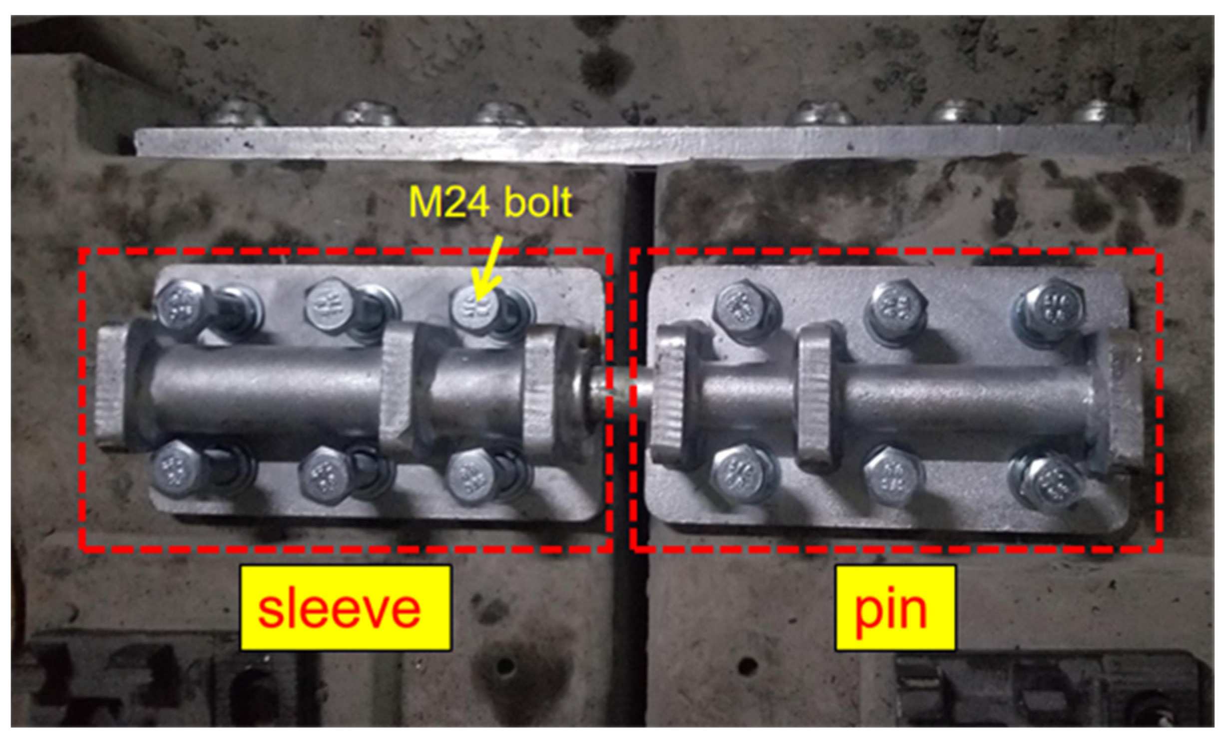
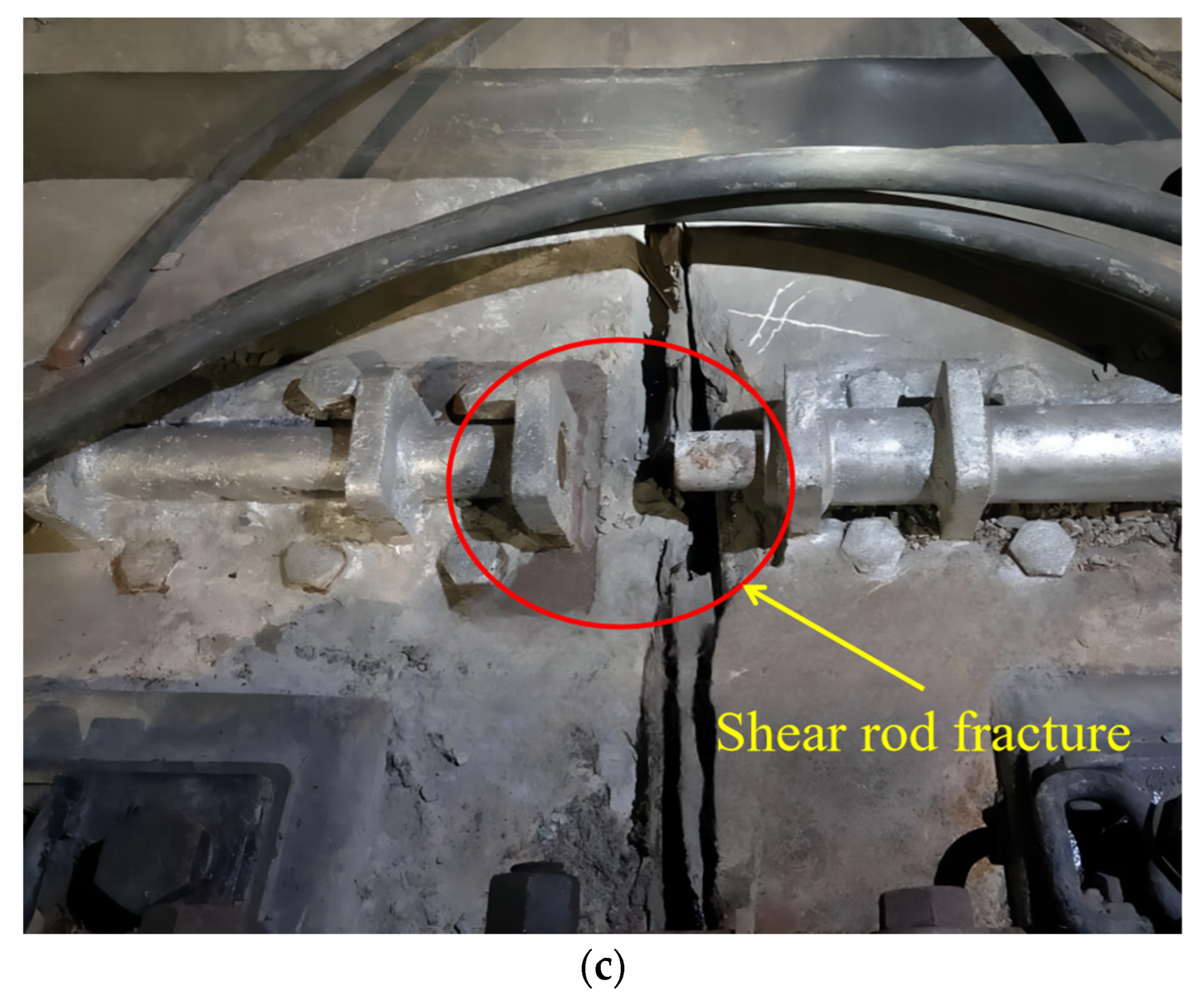
2.2. Damage to the TMSH
2.3. Analysis of the Causes of Damage to the TMSH
2.4. Structural Design Optimization
3. Finite-Element Modeling
3.1. TMSH Model
3.2. Material Properties, Constraints, and Load Settings
3.3. TMSH Strength-Check Calculation
4. Modal Analysis and Frequency-Response Analysis under Assembly Conditions
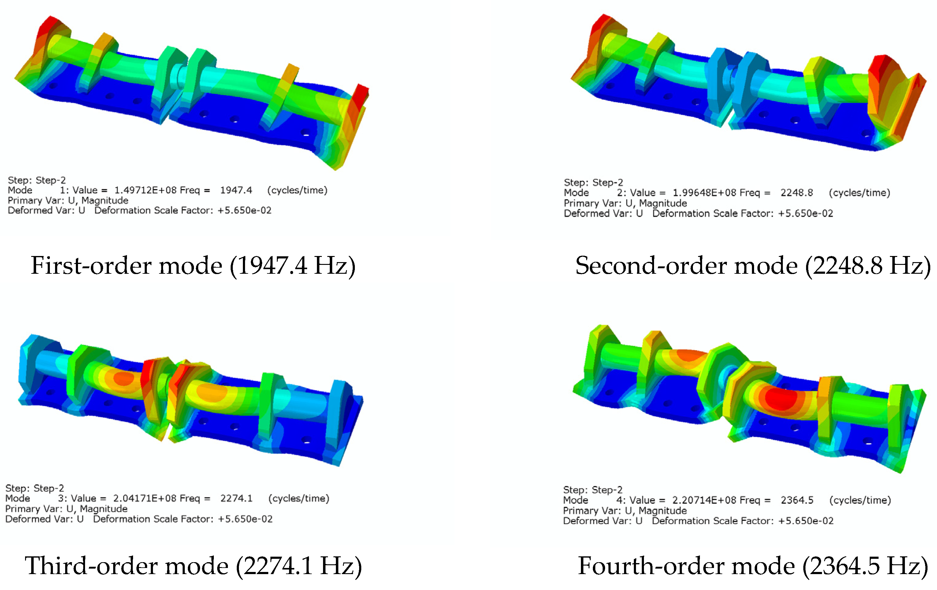
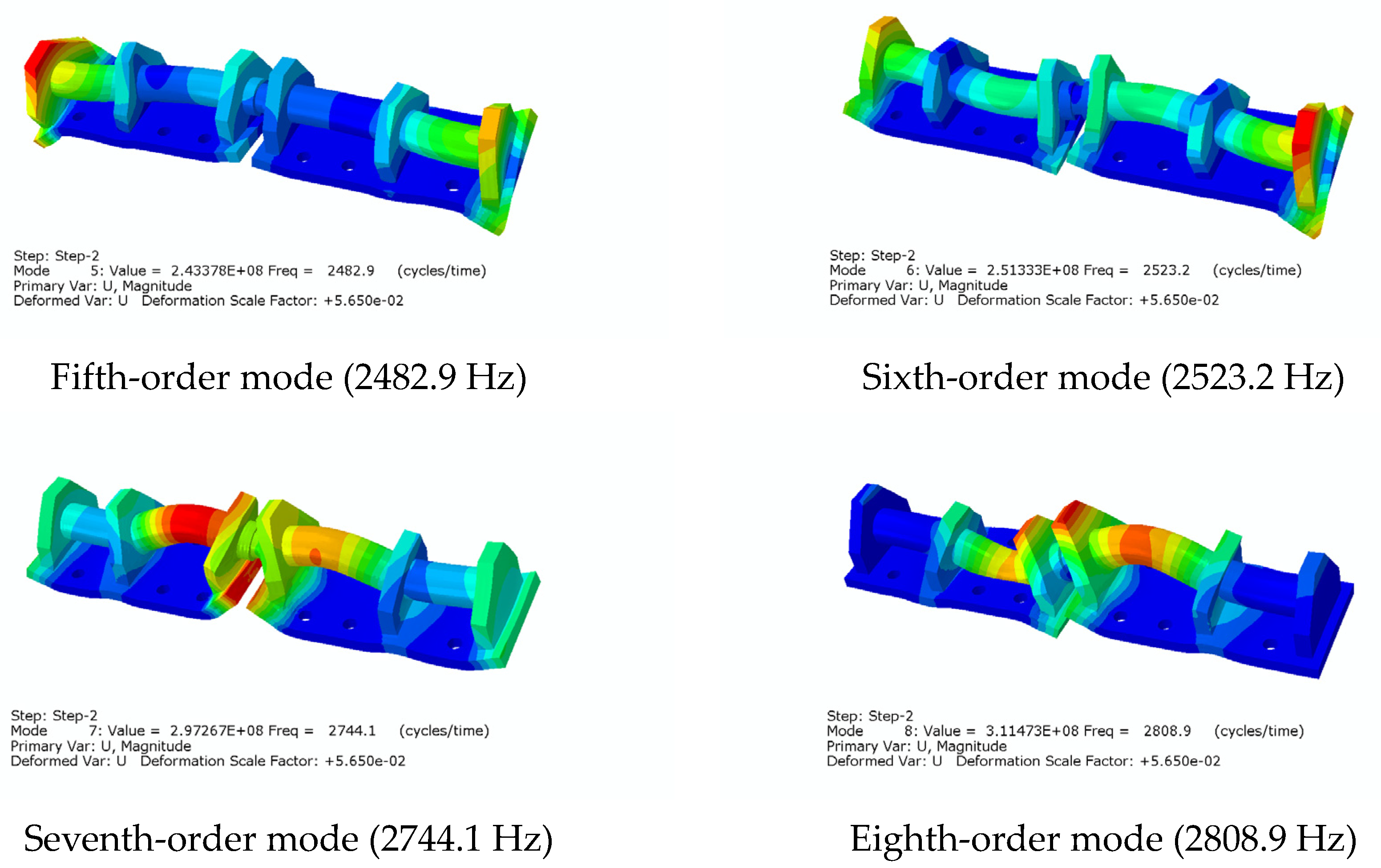
4.1. Analysis of TMSH Modalities When Using a Metal Pad
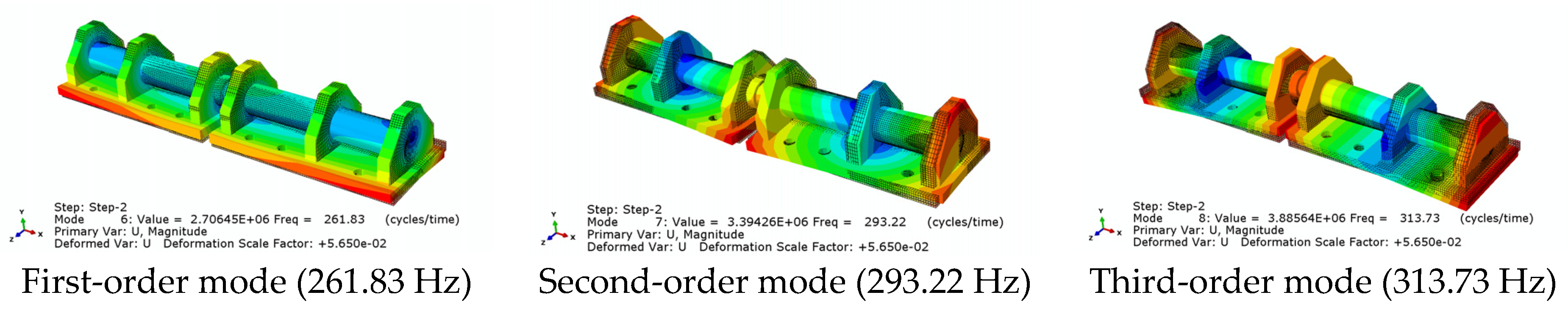
4.2. Analysis of TMSH Modalities When Using a Rubber Pad
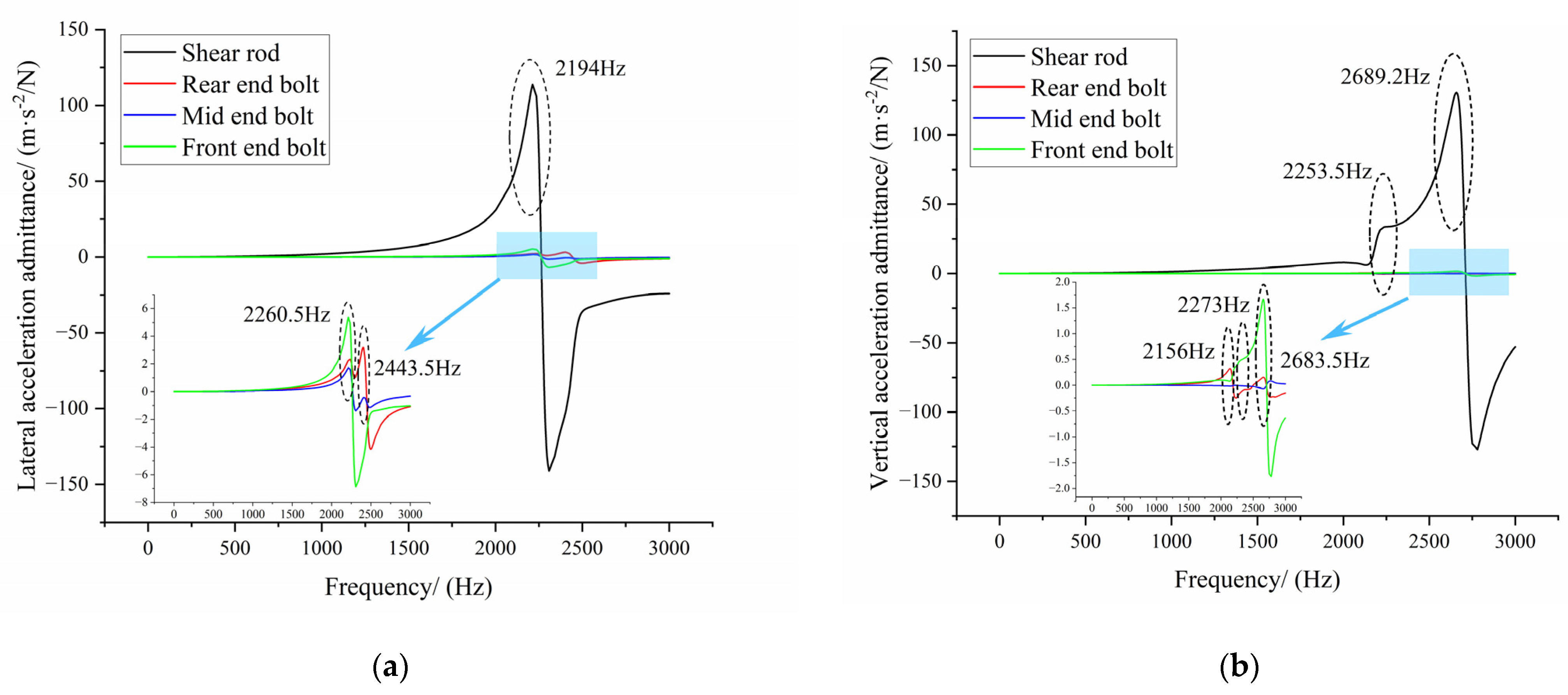
4.3. Analysis of Shear-Hinge Frequency-Response Function When Metal Padding Is Added
4.4. Analysis of Shear-Hinge Frequency-Response Function When Rubber Padding Is Added
5. Installation Modal Testing
5.1. Modal Test Principle
5.2. Modal Test under Installed Conditions
6. Conclusions
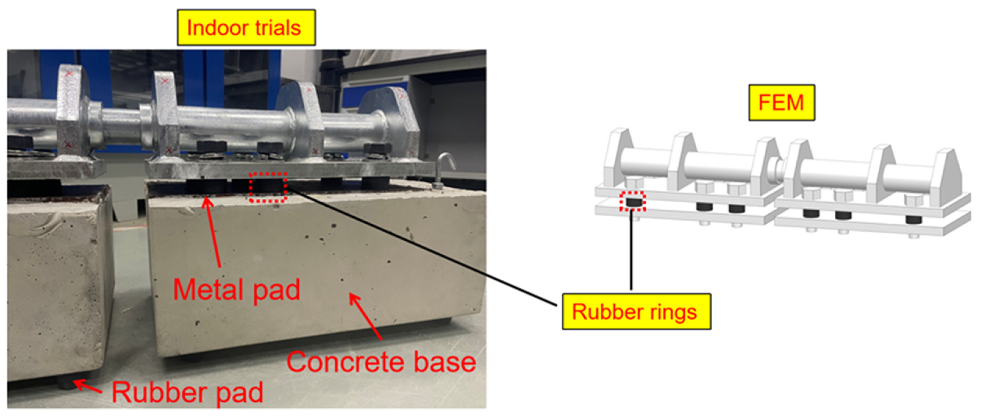
- Through field research, it was determined that the main damage to the top-mounted shear hinges was mainly characterized by shear-rod fracture, bolt loosening, and broken bolts. Among these, bolt loosening was common in both the new and old lines and the curved section had more damage compared to the straight section. Based on rubber-damping theory, a new structure was formed by adding rubber mats between the shear-hinge structure and the metal pad. It is expected that the service life will be extended by reducing the shear hinge’s natural frequency so that the natural frequency is located in the region of a lower vibration level of the floating-slab excitation, while also reducing the vibration amplitude in the higher part of the floating-slab excitation in the range of 400–3000 Hz.
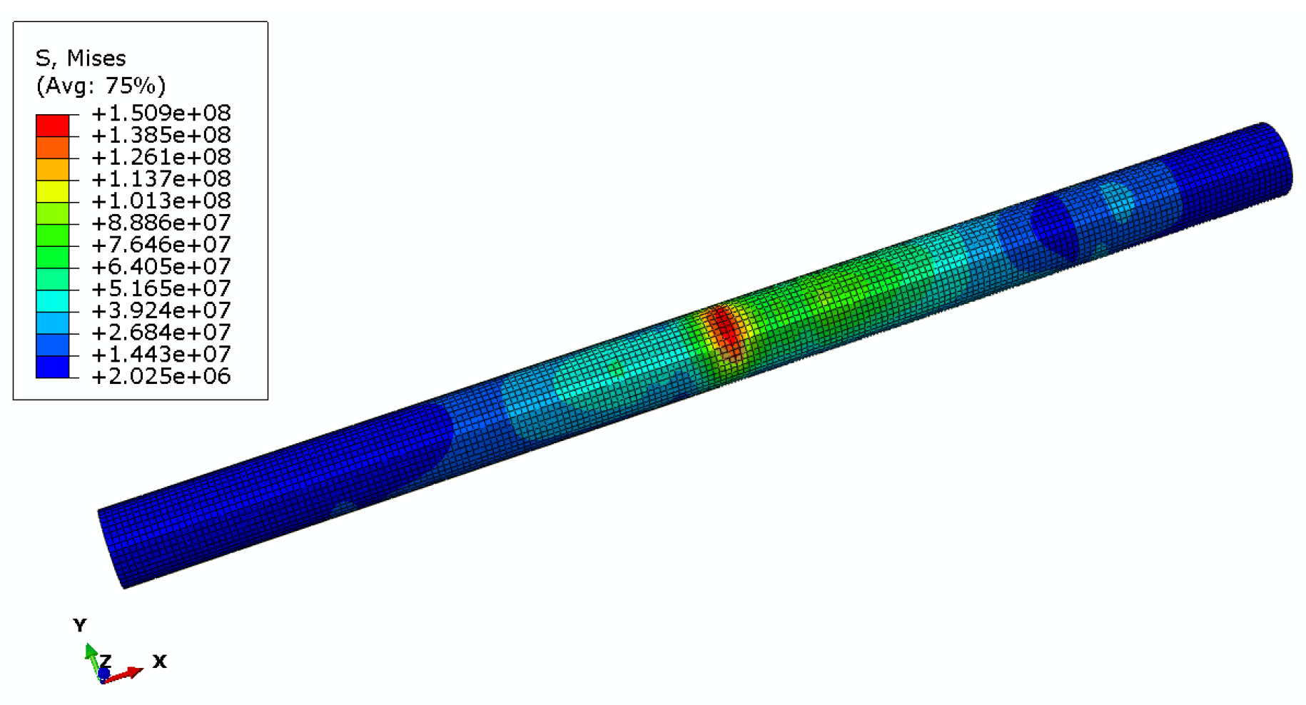
- By establishing a refined FEM of the SSFST and a refined model of the TMSH, the strength of the TMSH structure after the addition of the rubber pad was verified to be adequate. The pre-stress modal analysis of the TMSH assembly proved that the second-, third-, and seventh-order modes were the main causes of shear-rod fracture, and the reduced pre-stressing force under the third- and fifth-order modes of transverse vibration caused the bolts to loosen.
- Upon comparing the vibration levels of the TMSH structure before adding the rubber pad and after adding the rubber pad under four different working conditions, it was found that, except for the linear section, the vibration level caused by floating-slab excitation can be effectively reduced in the curved section. It was reduced by eight times in the 4.8 m curved section and by at least three times in the 3.6 m curved section. Therefore, it is tentatively believed that adding rubber padding to the curved section can effectively extend the service life of the TMSH.
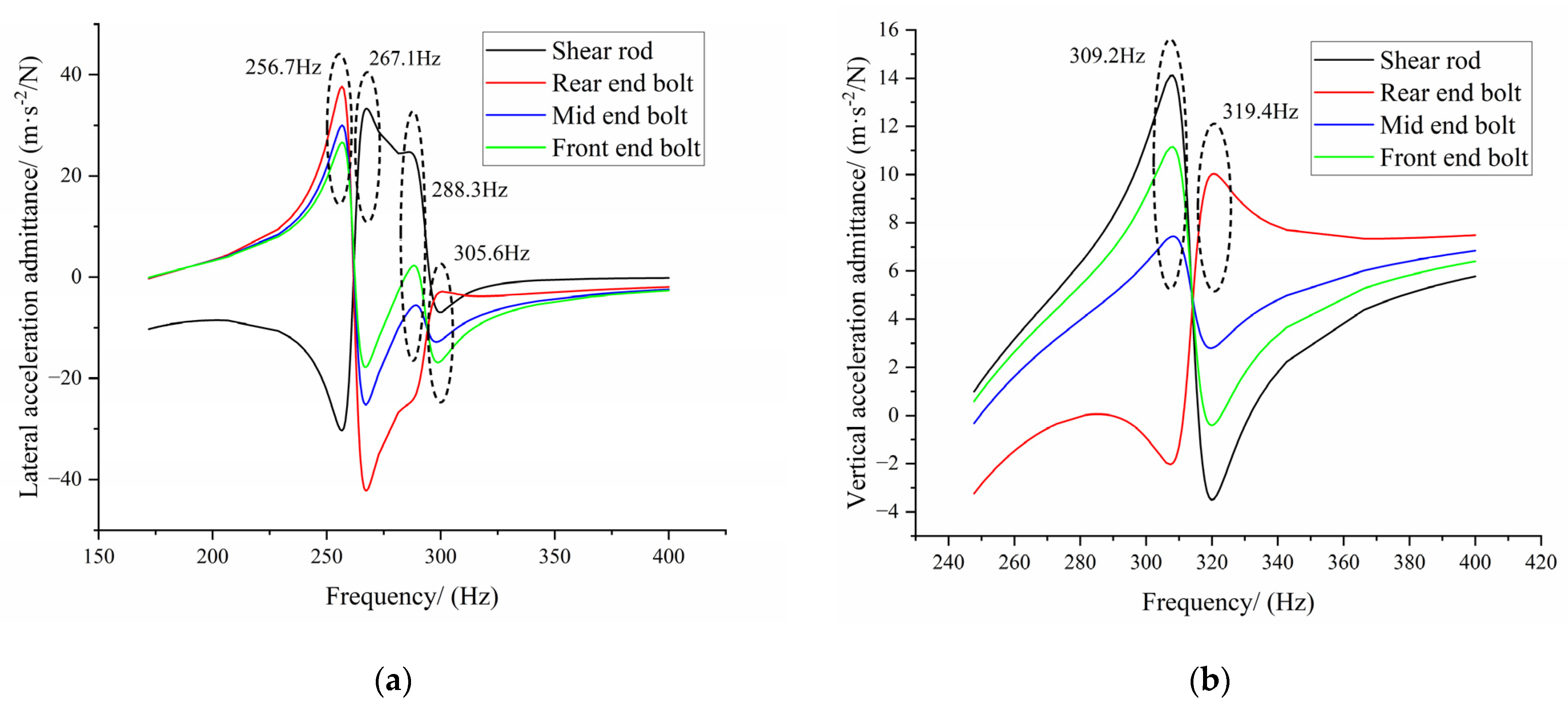
- After adding the rubber pad, some natural frequencies higher than 3000 Hz were reduced to 400–3000 Hz in the high-vibration area of the floating slab. Due to the damping effect of the rubber pad, the transverse vibration amplitude of the easily damaged parts was reduced by more than 30 dB. Additionally, the transverse vibration energy of the shear rod was attenuated by 59.71 dB, the vertical vibration amplitudes of the rear-end bolt and mid-end bolt were slightly increased, and the vertical vibration amplitudes of the shear rod and the front-end bolt were reduced by 47.97 dB and 5.28 dB, respectively. It has been proven that the rubber pad can effectively reduce the problems of shear-hinge fracture, bolt loosening, and broken bolts.
- The old and new TMSH structures were tested indoors using hammering tests to assess their modalities and validate the two simulation models separately. It was finally demonstrated, from both the test and simulation perspectives, that the new structure can effectively reduce the vibration amplitude of TMSHs when resonance occurs at the excited intrinsic frequency, thus delaying the occurrence of damage.
Author Contributions
Funding
Institutional Review Board Statement
Informed Consent Statement
Data Availability Statement
Conflicts of Interest
References
- Saurenman, H.; Phillips, J. In-Service Tests of the Effectiveness of Vibration Control Measures on the BART Rail Transit System. J. Sound Vib. 2006, 293, 888–900. [Google Scholar] [CrossRef]
- Wang, A.; Cox, S.J.; Huang, H.; Liu, L.; Jiang, J.; Sun, J. In-Car Noise and Carriage Floor Vibration on Different Track Forms and Curvatures in a Metro System. In Noise and Vibration Mitigation for Rail Transportation Systems; Schulte-Werning, B., Thompson, D., Gautier, P.-E., Hanson, C., Hemsworth, B., Nelson, J., Maeda, T., Vos, P., Eds.; Notes on Numerical Fluid Mechanics and Multidisciplinary Design; Springer: Berlin/Heidelberg, Germany, 2008; Volume 99, pp. 201–207. ISBN 978-3-540-74892-2. [Google Scholar]
- Huang, X.; Zeng, Z.; Wang, D.; Luo, X.; Li, P.; Wang, W. Experimental Study on the Vibration Reduction Characteristics of the Floating Slab Track for 160 Km/h Urban Rail Transit. Structures 2023, 51, 1230–1244. [Google Scholar] [CrossRef]
- CJJ/T 191-2012; Technical Specifications for Floating Slab Tracks. Ministry of Housing and Urban-Rural Development of the People’s Republic of China: Beijing, China, 2012. (In Chinese)
- Zhao, C.; Liu, D.; Zhang, X.; Yi, Q.; Wang, L.; Wang, P. Influence of Vibration Isolator Failure on Vehicle Operation Performance and Floating Slab Track Structure Vibration Reduction Effectiveness. Shock Vib. 2019, 2019, 1–14. [Google Scholar] [CrossRef]
- Xiao, X.; Jin, X.; Wen, Z. Effect of Track Support Failure on Dynamic Response of Tangent Track. Lixue Xuebao Chin. J. Theor. Appl. Mech. 2008, 40, 67–78. [Google Scholar]
- Zhan, T.; Yao, Y.; Li, J.; Liu, X.; Feng, Y. Influence of Fastener Failure on Dynamic Performance of Subway Vehicle. Appl. Sci. 2022, 12, 6769. [Google Scholar] [CrossRef]
- Xu, L.; Gao, J.; Zhai, W. On Effects of Rail Fastener Failure on Vehicle/Track Interactions. Struct. Eng. Mech. 2017, 63, 659–667. [Google Scholar] [CrossRef]
- Li, Q.; Wang, F.; Wang, Y.; Zhou, C.; Chen, J.; Forson, K.; Miao, R.; Su, Y.; Zhang, J. Effect of Reservoir Characteristics and Chemicals on Filtration Property of Water-Based Drilling Fluid in Unconventional Reservoir and Mechanism Disclosure. Environ. Sci. Pollut. Res. 2023, 30, 55034–55043. [Google Scholar] [CrossRef]
- Li, T.; Qin, A.; Pei, Y.; Sun, D.; Fu, X. Semianalytical Solutions to the Consolidation of Drainage Well Foundations in Unsaturated Soils with Radial Semipermeable Drainage Boundary under Time-Dependent Loading. Int. J. Geomech. 2020, 20, 04020150. [Google Scholar] [CrossRef]
- Wang, F.; Liu, X.; Jiang, B.; Zhuo, H.; Chen, W.; Chen, Y.; Li, X. Low-Loading Pt Nanoparticles Combined with the Atomically Dispersed FeN4 Sites Supported by FeSA-N-C for Improved Activity and Stability towards Oxygen Reduction Reaction/Hydrogen Evolution Reaction in Acid and Alkaline Media. J. Colloid Interface Sci. 2023, 635, 514–523. [Google Scholar] [CrossRef]
- Chung, W.; Kwon, K.; Jang, S.Y. Deflection-Based Load Transfer Efficiency of Floating Slab Track. KSCE J. Civ. Eng. 2014, 18, 616–624. [Google Scholar] [CrossRef]
- Hussein, M.; Alves Costa, P. The Effect of End Bearings on the Dynamic Behaviour of Floating-Slab Tracks with Discrete Slab Units. Int. J. Rail Transp. 2016, 5, 38–49. [Google Scholar] [CrossRef]
- Xu, Q.; Yan, B.; Lou, P.; Zhou, X. Influence of Slab Length on Dynamic Characteristics of Subway Train-Steel Spring Floating Slab Track-Tunnel Coupled System. Lat. Am. J. Solids Struct. 2015, 12, 649–674. [Google Scholar] [CrossRef] [Green Version]
- Xu, Q.; Xiao, Z.; Liu, T.; Lou, P.; Song, X. Comparison of 2D and 3D Prediction Models for Environmental Vibration Induced by Underground Railway with Two Types of Tracks. Comput. Geotech. 2015, 68, 169–183. [Google Scholar] [CrossRef]
- Wei, G.; Wang, Y.-A.; Jiang, J.-Q.; Zhang, R.; Ding, Z. Effect of Dowel Joints on Dynamic Behavior of Train–Discrete Floating Slab Track System. Adv. Mech. Eng. 2018, 10, 168781401876701. [Google Scholar] [CrossRef] [Green Version]
- Ma, D.; Shi, J.; Yan, Z.; Xiao, J.; Sun, L. Experimental and Numerical Investigation of the Effect of the Assembled State on the Static-Dynamic Characteristics and Fatigue Performance of Railway Fastening Clips. Structures 2022, 46, 1808–1822. [Google Scholar] [CrossRef]
- Xiao, H.; Wang, J.-B.; Zhang, Y.-R. The Fractures of E-Type Fastening Clips Used in the Subway: Theory and Experiment. Eng. Fail. Anal. 2017, 81, 57–68. [Google Scholar] [CrossRef]
- Gao, X.; Wang, A.; Liu, L.; He, Y.; Ju, L. Analysis of Failure Mechanism of W1-Type Fastening Clip in High Speed Railway and Structure Study of Damping Composite. Eng. Fail. Anal. 2020, 118, 104848. [Google Scholar] [CrossRef]
- Dai, W.; Moroni, M.O.; Roesset, J.M.; Sarrazin, M. Effect of Isolation Pads and Their Stiffness on the Dynamic Characteristics of Bridges. Eng. Struct. 2006, 28, 1298–1306. [Google Scholar] [CrossRef]
- Xin, T.; Ding, Y.; Wang, P.; Gao, L. Application of Rubber Mats in Transition Zone between Two Different Slab Tracks in High-Speed Railway. Constr. Build. Mater. 2020, 243, 118219. [Google Scholar] [CrossRef]
- Liu, T.; Rao, R.; Liu, J.; Ye, M.; Huang, Y. Experimental Study on the Damping Effects of Various Vibration Reduction Measures. IOP Conf. Ser. Mater. Sci. Eng. 2020, 735, 012067. [Google Scholar] [CrossRef] [Green Version]
- Jin, H.; Zhou, S.; Liu, W. Optimization of Vibration Reduction of the Rubber Floating-Slab Tracks. J. Vibroeng. 2017, 19, 1214–1224. [Google Scholar] [CrossRef] [Green Version]
- Jin, H.; Liu, W.; Zhou, S. An Experiment to Assess Vibration Reduction Ability of the Rubber Floating-Slab Tracks with Different Supporting Forms. J. Vibroeng. 2015, 17, 3237–3246. [Google Scholar]
- Luo, R.K.; Mortel, W.J.; Wu, X.; Peng, L.M. Evaluation of Stress Softening of the Rubber Suspension Used on Rail Vehicles. Proc. Inst. Mech. Eng. Part F J. Rail Rapid Transit 2016, 230, 15–23. [Google Scholar] [CrossRef]
- Zhao, C.; Shi, D.; Zheng, J.; Niu, Y.; Wang, P. New Floating Slab Track Isolator for Vibration Reduction Using Particle Damping Vibration Absorption and Bandgap Vibration Resistance. Constr. Build. Mater. 2022, 336, 127561. [Google Scholar] [CrossRef]
- Liu, W.; Miyama, T.; Feng, D.; Zhou, F. Simplified Calculation Method for Vertical Stiffness of Rubber Isolation Bearings. Earthq. Eng. Eng. Vib. 2001, 21, 111–116. (In Chinese) [Google Scholar] [CrossRef]
- GB 20688.3-2006; Rubber bearings—Part 3: Rubber bearings for seismic isolation of buildings. General Administration of Quality Supervision, Inspection and Quarantine of the People’s Republic of China: Beijing, China, 2006. (In Chinese)
- Huang, X.; Zeng, Z.; Li, Z.; Wang, W.; Yuan, Y.; Yuan, W.; Boumedienne, H.S. Comparative Research on Vibration Characteristics of Cast-In-Place Steel-Spring-Floating Slab Track under Different Subway Line Conditions. Appl. Sci. 2022, 12, 5079. [Google Scholar] [CrossRef]
- Tang, M.-Z.; Xiong, X.-H.; Li, X.-B.; Chen, G.; Zhang, J.; Zhong, M.; Sun, B. Dynamic Response of Outer Windshield Structure in Different Schemes under Aerodynamic Load. Appl. Sci. 2023, 13, 3879. [Google Scholar] [CrossRef]
- Jiang, C.; Xiong, W.; Cai, C.S.; Zhu, Y.; Wang, J. Preload Loss of High-Strength Bolts in Friction Connections Considering Corrosion Damage and Fatigue Loading. Eng. Fail. Anal. 2022, 137, 106416. [Google Scholar] [CrossRef]
- Wang, Y.-Z.; Li, G.-Q.; Wang, Y.-B.; Lyu, Y.-F. Simplified Method to Identify Full von Mises Stress-Strain Curve of Structural Metals. J. Constr. Steel Res. 2021, 181, 106624. [Google Scholar] [CrossRef]
- TB/T 10082-2005; Railway Track Design Specifications. National Railway Administration of the People’s Republic of China: Beijing, China, 2005. (In Chinese)
- Zeng, Z.; Huang, X.; Li, Z.; Wang, W.; Shi, Z.; Yuan, Y.; Shuaibu, A.A. Experimental Research on Vibration-Damping Effect of Combined Shear Hinge Prefabricated Steel Spring Floating Slab Track. Sensors 2022, 22, 2567. [Google Scholar] [CrossRef]
- Luczak, M.M.; Riva, R.; Yeniceli, S.C.; Madsen, S.H.; Di Lorenzo, E. Identification of the Test Setup Influence on the Modal Properties of a Short Wind Turbine Blade during Fatigue Test. Measurement 2021, 174, 108960. [Google Scholar] [CrossRef]
- Lei, X.; Jiang, C. Analysis of Vibration Reduction Effect of Steel Spring Floating Slab Track with Finite Elements. J. Vib. Control 2016, 22, 1462–1471. [Google Scholar] [CrossRef]


| Line Type | Loose Bolts | Broken Bolts | Pin or Shear-Rod Fracture | |||
|---|---|---|---|---|---|---|
| Quantity (pcs) | Percentage (%) | Quantity (pcs) | Percentage (%) | Quantity (pcs) | Percentage (%) | |
| Old line straight | 20 | 4.4 | 2 | 0.4 | 1 | 2.6 |
| Old line curved | 31 | 6.8 | 10 | 2.2 | 3 | 7.9 |
| New line straight | 16 | 1.8 | 0 | 0 | 0 | 0 |
| New line curved | 48 | 5.3 | 11 | 1.2 | 2 | 2.6 |
| IRHD | κ | n | ||
|---|---|---|---|---|
| 70 | 7.34 | 0.53 | 1270 | 1 |
| Material | Young’s Modulus/Pa | Poisson’s Ratio | Density kg/m3 |
|---|---|---|---|
| 60Si2Mn | 2.01 × 10¹¹ | 0.29 | 7850 |
| Rubber | 1.5 × 10⁶ | 0.4995 | 1300 |
| Component | Parameter | Value |
|---|---|---|
| Prefabricated floating slab | Floating-slab size | |
| Young’s modulus | ||
| Density | ||
| Poisson’s ratio | ||
| Steel-spring isolator | Vertical stiffness | |
| Lateral stiffness | ||
| Vertical damping | ||
| Layout distance | ||
| Fastener | Vertical stiffness | |
| Lateral stiffness | ||
| Vertical damping | ||
| Rail | Mass | |
| Young’s modulus |
| Order | Frequency/Hz | Description of the Vibration Mode |
|---|---|---|
| First | 1947.4 | First-order bending, front and rear sleeve warping at the opposite end, asymmetric bending of the shear rod, large amplitude at the rear end |
| Second | 2248.8 | Second-order bending, front and rear of sleeve warped at the same end, shear rod bent symmetrically, large amplitude at the rear end |
| Third | 2274.1 | First-order torsion, both ends of the sleeve along the shear rod undergo axial counterclockwise rotation, the front amplitude is large |
| Fourth | 2364.5 | Second-order torsion, both ends of the sleeve along the axial axis of the shear rod undergo clockwise rotation, the front-end amplitude is large |
| Fifth | 2482.9 | Third-order torsion, both sides of the sleeve along the shear rod undergo axial anisotropic rotation, both ends of the sleeve undergo anisotropic rotation, the rear end amplitude is large |
| Sixth | 2523.2 | Fourth-order torsion, both ends of the sleeve along the axial direction of the shear rod undergo counterclockwise rotation, both ends of the sleeve undergo the same direction of rotation, the rear end amplitude is large |
| Seventh | 2744.1 | Third-order bending, front and rear of sleeve warped at the same end, shear rod bent symmetrically, large amplitude at the rear end |
| Eighth | 2808.9 | Fourth-order bending, front and rear of sleeve warped at opposite ends, asymmetric bending of the shear rod, large amplitude at the rear end |
| Order | Frequency/Hz | Description of the Vibration Mode |
|---|---|---|
| First | 261.83 | The TMSH is rotated along the x-axis and slightly bent along the z-axis. |
| Second | 293.22 | The TMSH is bent along the z-axis |
| Third | 313.73 | The TMSH is bent along the y-axis |
| Order | Metal Pad | Rubber Pad | Modal Improvement Rate |
|---|---|---|---|
| First | 1947.4 | 261.8 | 86.6% |
| Second | 2248.8 | 293.2 | 87% |
| Third | 2274.1 | 313.7 | 86.2% |
| Working Conditions | Drop-Hammer Impact Test—3.6 m | Drop-Hammer Impact Test—4.8 m | Straight-Line Vibration Test—SSFST | Curved-Line Vibration Test—SSFST |
|---|---|---|---|---|
| Serial number | 1 | 2 | 3 | 4 |
| dB difference/dB | 3 | 9 | −8 | 9 |
| Work Conditions | Shear Rod | Rear-End Bolt | Mid-End Bolt | Front-End Bolt |
|---|---|---|---|---|
| Metal pad/dB | 161.29 | 129.54 | 122.28 | 134.32 |
| Rubber pad/dB | 101.58 | 95.56 | 87.96 | 87.23 |
| Improvement value/dB | 59.71 | 33.98 | 34.32 | 47.09 |
| Work Conditions | Shear Rod | Rear-End Bolt | Mid-End Bolt | Front-End Bolt |
|---|---|---|---|---|
| Metal pad/dB | 162.29 | 110.63 | 105.58 | 124.60 |
| Rubber pad/dB | 114.32 | 113.56 | 114.50 | 119.32 |
| Improvement value/dB | 47.97 | −2.93 | −8.92 | 5.28 |
| Name | Sensitivity (mv/g) | Frequency Range Hz |
|---|---|---|
| PCB 352C33/ICP | 100 | 0.5–10,000 Hz |
| PCB 353B31/ICP | 50 | 1–5000 Hz |
| IRHD | κ | n | ||
|---|---|---|---|---|
| 60 | 5.34 | 0.57 | 1150 | 1 |
| Mode Order | Experimental Mode/Hz | Experimental Nephogram | Simulation Mode/Hz | Simulation Nephogram | Error |
|---|---|---|---|---|---|
| 1 | 1763.5 |  | 1947.4 |  | 9.4% |
| 2 | 2022.6 |  | 2248.8 |  | 10% |
| 7 | 2681.0 |  | 2744.1 | 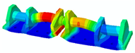 | 2.2% |
| 8 | 2998.6 | 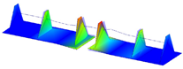 | 2808.9 |  | 6.3% |
| Mode Order | Experimental Mode/Hz | Experimental Nephogram | Simulation Mode/Hz | Simulation Nephogram | Error |
|---|---|---|---|---|---|
| 2 | 301.5 | 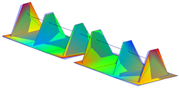 | 293.2 | 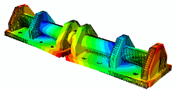 | 2.8% |
| 3 | 325.2 | 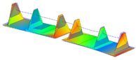 | 313.7 | 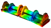 | 3.5% |
Disclaimer/Publisher’s Note: The statements, opinions and data contained in all publications are solely those of the individual author(s) and contributor(s) and not of MDPI and/or the editor(s). MDPI and/or the editor(s) disclaim responsibility for any injury to people or property resulting from any ideas, methods, instructions or products referred to in the content. |
© 2023 by the authors. Licensee MDPI, Basel, Switzerland. This article is an open access article distributed under the terms and conditions of the Creative Commons Attribution (CC BY) license (https://creativecommons.org/licenses/by/4.0/).
Share and Cite
En, H.; He, Y.; Lu, H.; Wang, A. A New Top-Mounted Shear-Hinge Structure Based on Modal Theory and Rubber-Pad Damping Theory. Appl. Sci. 2023, 13, 8661. https://doi.org/10.3390/app13158661
En H, He Y, Lu H, Wang A. A New Top-Mounted Shear-Hinge Structure Based on Modal Theory and Rubber-Pad Damping Theory. Applied Sciences. 2023; 13(15):8661. https://doi.org/10.3390/app13158661
Chicago/Turabian StyleEn, He, Yuelei He, Hongyao Lu, and Anbin Wang. 2023. "A New Top-Mounted Shear-Hinge Structure Based on Modal Theory and Rubber-Pad Damping Theory" Applied Sciences 13, no. 15: 8661. https://doi.org/10.3390/app13158661