Article

The Teaching Application of the Backward Design Method in Chinese National Undergraduate Engineering Training Integration Ability Competition: Take the Double 8 Carbon-Free Car as an Example

College of Mechanical and Electrical Engineering, Tarim University, Alar 843300, China
*
Authors to whom correspondence should be addressed.
Appl. Sci. 2023, 13(15), 8829; https://doi.org/10.3390/app13158829
Submission received: 29 May 2023 / Revised: 21 July 2023 / Accepted: 24 July 2023 / Published: 31 July 2023

Abstract

:
National Undergraduate Engineering Training Integration Ability Competition is essential in Chinese engineering colleges. Among these items, the carbon-free car competition is popular among college students because of its flexible track, challenging design tasks, and fair judging criteria. In this study, to design a reasonable carbon-free car structure according to the track given by the competition, a reverse analysis method was proposed for the double 8-shaped carbon-free car trajectory based on the space cam mechanism. First, the carbon-free car’s structure was designed, and its stress state was analyzed, with the results indicating that the driving force should be reduced as much as possible under the premise of satisfying the starting requirements to increase the travel distance of the carbon-free car with no slipping. Then, the function between the car track and the front wheel swing angle was established, and the displacement law of the push rod of the cam mechanism was calculated through the swing angle of the front wheel. Finally, the cam profile was got based on the operating law of the push rod. Research has shown that compared with the traditional forward design, this method was more accurate with strong feasibility and operability, which provided good technical support for designing the subsequent carbon-free car competition.

1. Introduction

The National Undergraduate Engineering Training Integration Ability Competition has been held in China every two years since 2009. Up until now, seven competitions have been held. Many students from 34 provinces, municipalities, autonomous regions and the Xinjiang Production and Construction Corps participated actively regularly. In 2021, 19,000 teams involving 66,000 students from 690 colleges and universities participated in the competition (The data can be viewed from the following website: http://www.gcxl.edu.cn/new/index.html (accessed on 13 June 2023). The competition’s content includes basic engineering competition, virtual simulation competition and smart car competition. Among them, the carbon-free car competition, which belongs to the basic engineering category, is widely welcomed by mechanical students. According to the track designated by the annual competition, the competition was equipped with wooden stakes as obstacles, and the overall structure and size of carbon-free cars needed to be designed according to the requirements for the competition [1].
Carbon-free car is driven by gravitational potential energy with the function of established direction control. When the carbon-free car moves forward, the gravitational potential energy is converted into the car’s energy moving [2]. During the competition, the carbon-free car should be started from the initial point and avoid obstacles. Meanwhile, the weight with a mass of 1 kg (ordinary carbon steel φ50 mm × 65 mm) starts to fall vertically, dropping 400 ± 2 mm. During the falling process of the weight, the weight was required to move along with the car and must not fall from the car. In addition, the car was required to be a three-wheel structure, and the car steering control mechanism was adjustable to adapt to the competition field with different spacing obstacles [3]. The competition would be terminated if the car deviated seriously from the track and hit a stake or if the car stopped due to lack of power. The longer the driving route, the higher the performance.
As shown in Figure 1, the thin wire connects weight with spool 10 through pulley mechanism 2, and the carbon-free car is driven with weight 3 falling from the initial position. The thin wire is wound dozens of times on spool 10 in the initial state of a carbon-free car. When weight 3 falls by its gravity, spool 10 is driven to rotate through the pulley mechanism 3, and the drive wheel 9 is driven to rotate synchronously so that the car moves forward [4]. At the same time, spool 10 transmits motion and power to cam 5 through gear transmission mechanism 8. The cam pushes the swing rod 6 to move during the rotation process and finally changes the driving direction of the front wheel 7. When designing a carbon-free car, the cam profile design is an important task. Only by designing the profile reasonably the car can have an accurate steering law according to the requirements of the competition.
In previous competitions, many contestants have utilized the forward analysis method to design, process, and assemble the structure of carbon-free cars based on their experience. This involves designing based on existing carbon-free car structures with approximate requirements and continuously modifying key components’ size or geometric parameters based on practical results [5,6]. The forward design method is simple and easy to understand. However, it may not provide a clear trajectory for the carbon-free car without running a demonstration and may require extensive debugging to achieve the desired results [7,8]. As a result, this design concept is relatively outdated. The reverse design of the carbon-free car involves starting with the trajectory provided by the competition and deducing the critical parameters of the transmission mechanism (cam mechanism) based on this trajectory. Subsequently, a carbon-free car is designed using these parameters. This method has been relatively less studied. This method can significantly reduce the workload required for debugging and shorten the design cycle. The reverse design method can also provide a solidified step for many contestants. So, it is necessary to study it in depth.
A cam mechanism is a more appropriate transmission mechanism for complex trajectory requirements [9]. Designing a cam profile that meets the trajectory requirements is crucial for successfully moving a carbon-free car along a predetermined route [10]. This study proposed a reverse analysis method for the double 8-shaped carbon-free car trajectory based on the space cam mechanism. An ideal trajectory mathematical equation was established, and various car parameters and theoretical running trajectories were calculated through mathematical modeling. This method reduced the cost of trial and error, shortened the debugging cycle, and was highly versatile. The general idea is: the structure and dimensions of all components of the carbon-free car, except for the cam structure, should be determined based on previous experience. Once this is done, the cam profile can be deduced using the reverse design method based on the given trajectory. This research can provide technical and theoretical support for the later design of zero-carbon vehicles adapted to different routes.

2. Materials and Methods

The reverse analysis method was used to design the carbon-free car, beginning with the ideal trajectory and overall structure. Initial parameters were determined, and the functional relationship between mechanisms was identified, allowing for establishing a mathematical model based on the predetermined trajectory and parameters. The cam was then determined using the mathematical model and algorithmic geometric parameters to generate the cam profile, ultimately enabling the car to travel along the predetermined trajectory [6,11].
This study utilized the control variable method and drew on previous competition data to design the basic structure of a carbon-free car, with a focus on reserving design space for the cam mechanism. The carbon-free car’s structure was designed, and its stress state was analyzed to ensure the rationality of mechanical structure design. The function between the car track and the front wheel swing angle was established, and the displacement law of the push rod of the cam mechanism was calculated through the swing angle of the front wheel. Based on the operating law of the push rod, the cam profile was reversed. The research primarily utilized MATLAB 2022a for calculations and VISO 2020 and CAD 2020 for illustration drawings.

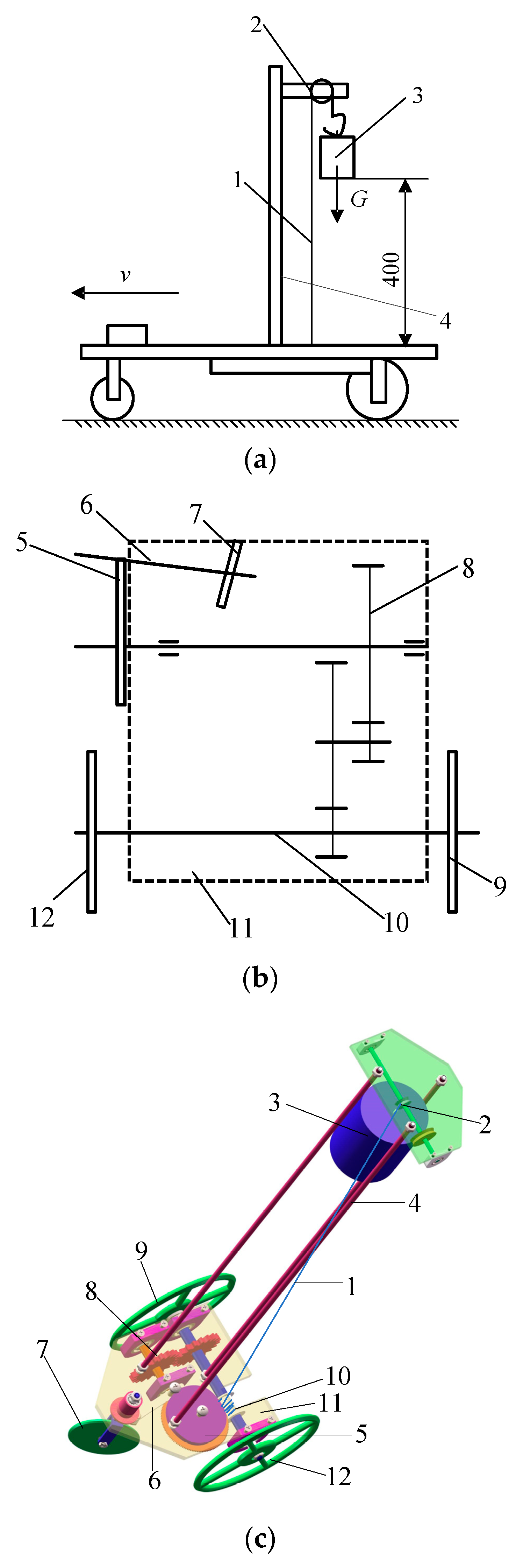
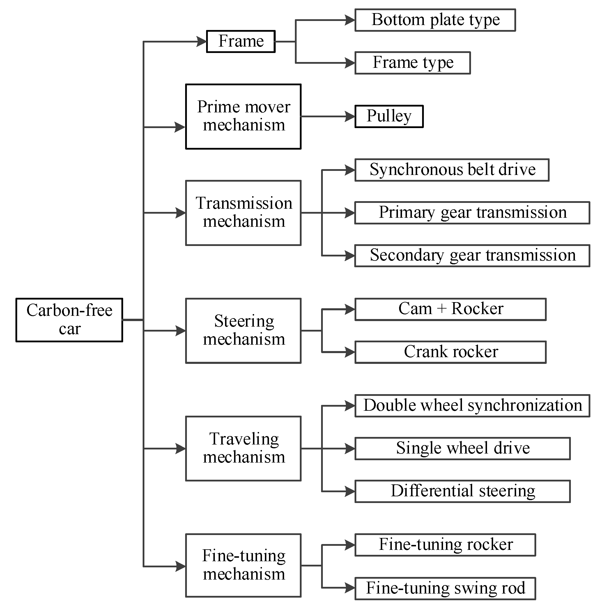
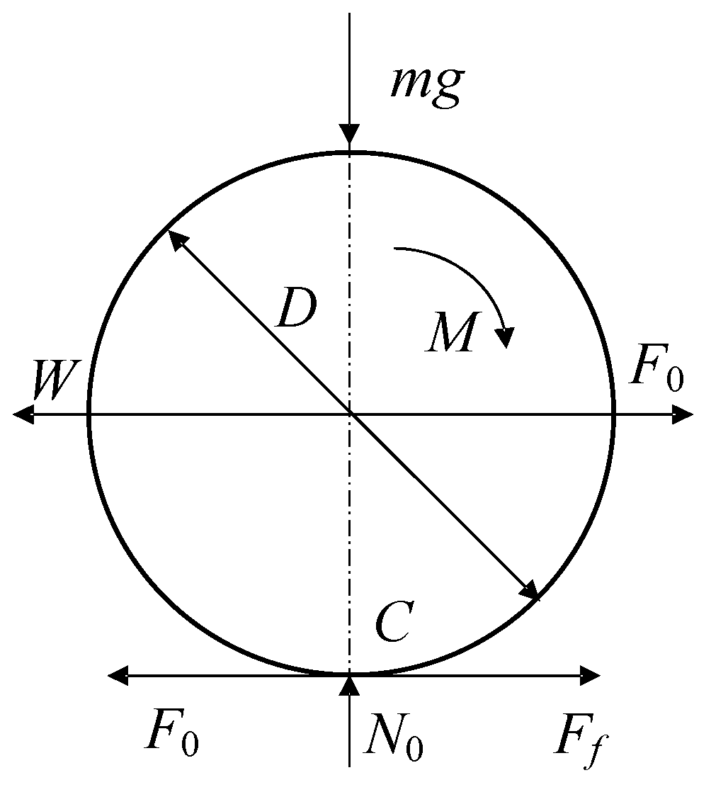
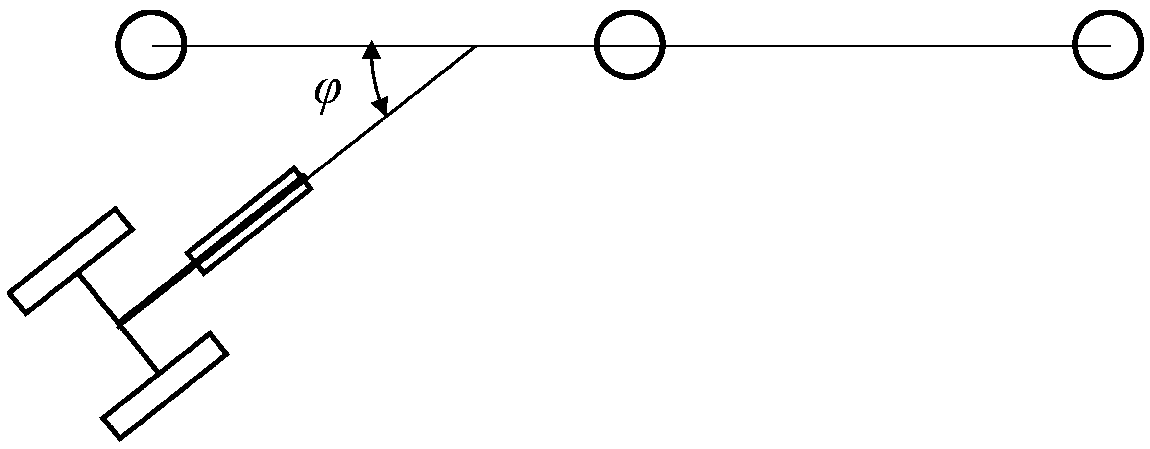
3. Overall Structure Design and Force Analysis

Through the analysis of the excellent entries in the previous six national undergraduate engineering training integration ability competitions over the years, the carbon-free car is mostly composed of six parts: frame, prime mover mechanism, transmission mechanism, steering mechanism, traveling mechanism, and fine-tuning mechanism. The main components and common realization mechanisms of the carbon-free car are shown in Figure 2 [12,13,14].
This design is based on the control variable method, and the carbon-free car’s length, width, and height are set to be 120 mm × 140 mm × 575 mm. The bottom plate is made of an acrylic plate with a thickness of 5 mm, which strives for a compact structure for improving the fault tolerance rate of the carbon-free car; the pulley mechanism was used as the prime mover, and three aluminium alloy tubes with a length of 400 mm were selected as the support frame of the pulley; the transmission mechanism was composed of 1~2 groups of gear transmission mechanisms according to the specific track; the steering mechanism adopted a cam mechanism, which could adapt to different tracks by changing the cam profile; the walking mechanism adopted a single-wheel drive, and the material was an acrylic plate with a radius of 65 mm and a thickness of 2 mm; the fine-tuning mechanism was to adjust the swing angle of the steering wheel by changing the length of the push rod and the connecting rod, for correcting the deviation caused by the influence of different venues.
When designing the mechanical structure of the carbon-free car, the car was required to run smoothly in the process of obstacle avoidance, and its force analysis was required. Let m be the car mass, N0 be the supporting reaction force of the car on the ground, F0 be the driving force of the car, and G be the gravitational acceleration. The whole car is taken as the research object, and the simplified mechanical model is shown in Figure 3.
mg = N0
The driving torque of the car is:
M = F 0 × D 2
where, D 2 is the driving force arm.
Then the driving force of the car is:
F 0 = 2 M D
The carbon-free car converts the potential energy of gravity into the mechanical energy of the wheels, ignoring the problem of transmission efficiency, and the driving torque M is converted from the weight gravity of the carbon-free car.
M = G ϕ 2 = F 0
where, ϕ 2 is the force arm of gravity.
Then the driving force is:
F 0 = G · ϕ D
The carbon-free car is subject to running resistance when moving forward, which includes inertia resistance (especially in the car starting acceleration stage, set the acceleration as a) and static resistance. Where, the inertia resistance Na is:
Na = ma
Static resistance generally included the basic resistance Nb in the transmission chain and the friction resistance Ff between the wheel and the ground. The basic resistance Nb is:
Nb = mgw
w is the running resistance coefficient, and the empirical data obtained from the experiment is about 0.01. Therefore, the condition that needs to be met to make the carbon-free car start smoothly is:
F0 > m(a + gw)
Then the condition for a non-slip carbon-free car is:
F0 < Ff = mgf
where f is the friction coefficient between the car and the ground. Let S be the traveling distance of the car, and η be the total efficiency of the car. Then the work done during the falling process of the weight is:
F0S = mghη
Then there is:
S = mghη/F0
As shown in the above formulas, the driving force should be reduced as much as possible to satisfy the starting requirements to increase the travel distance of the carbon-free car with no slipping.

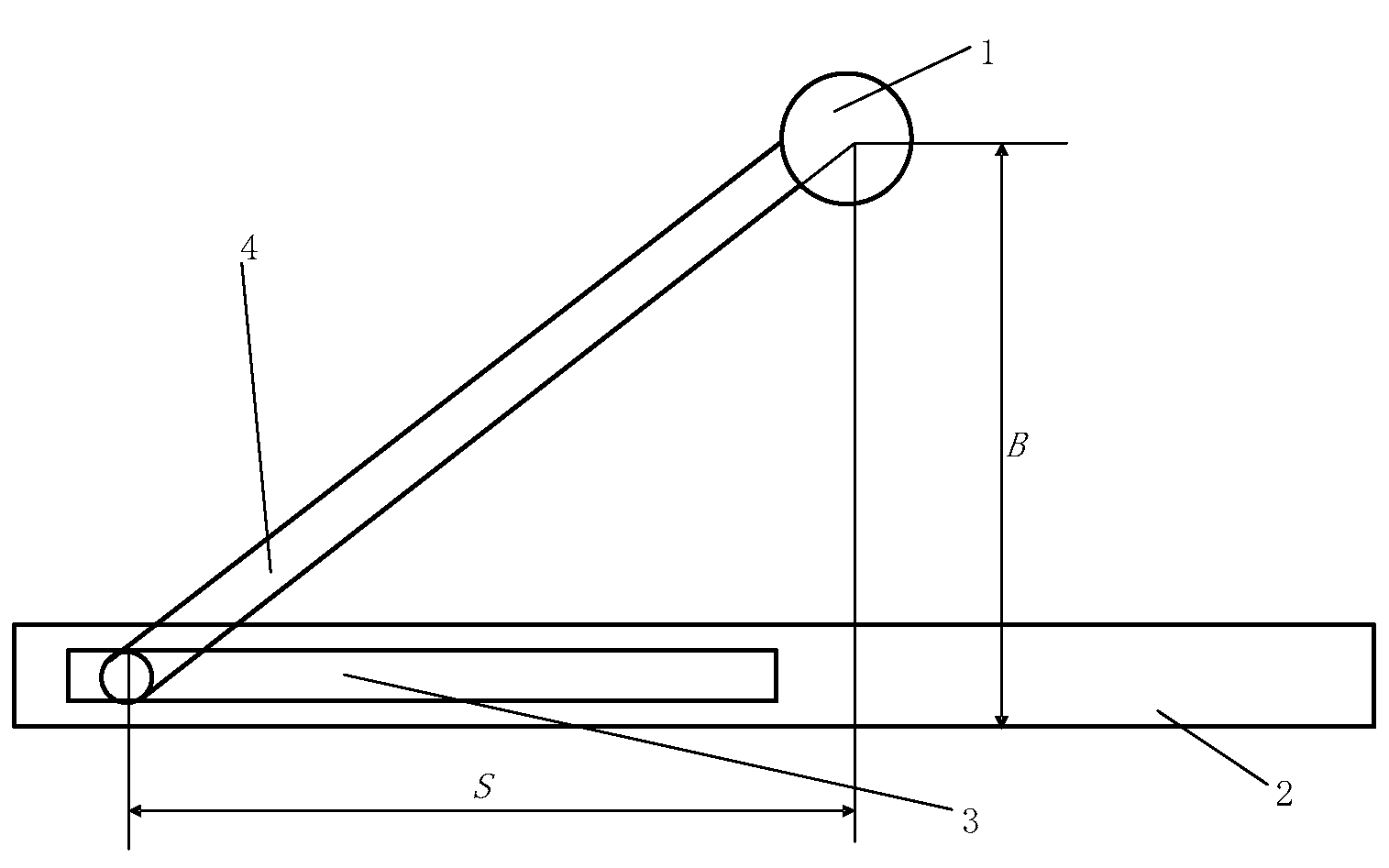
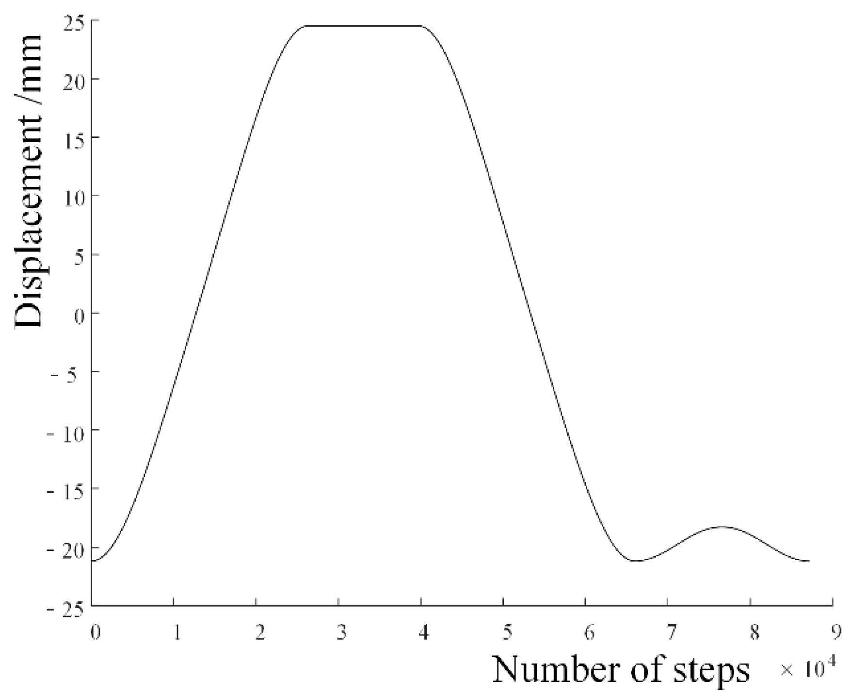
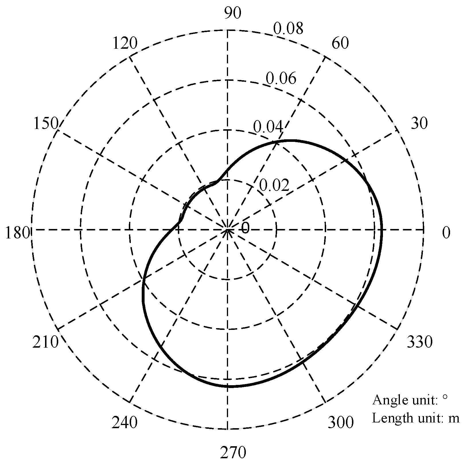
4. Cam Profile Design of the Carbon-Free Car for Double 8-Shaped Track

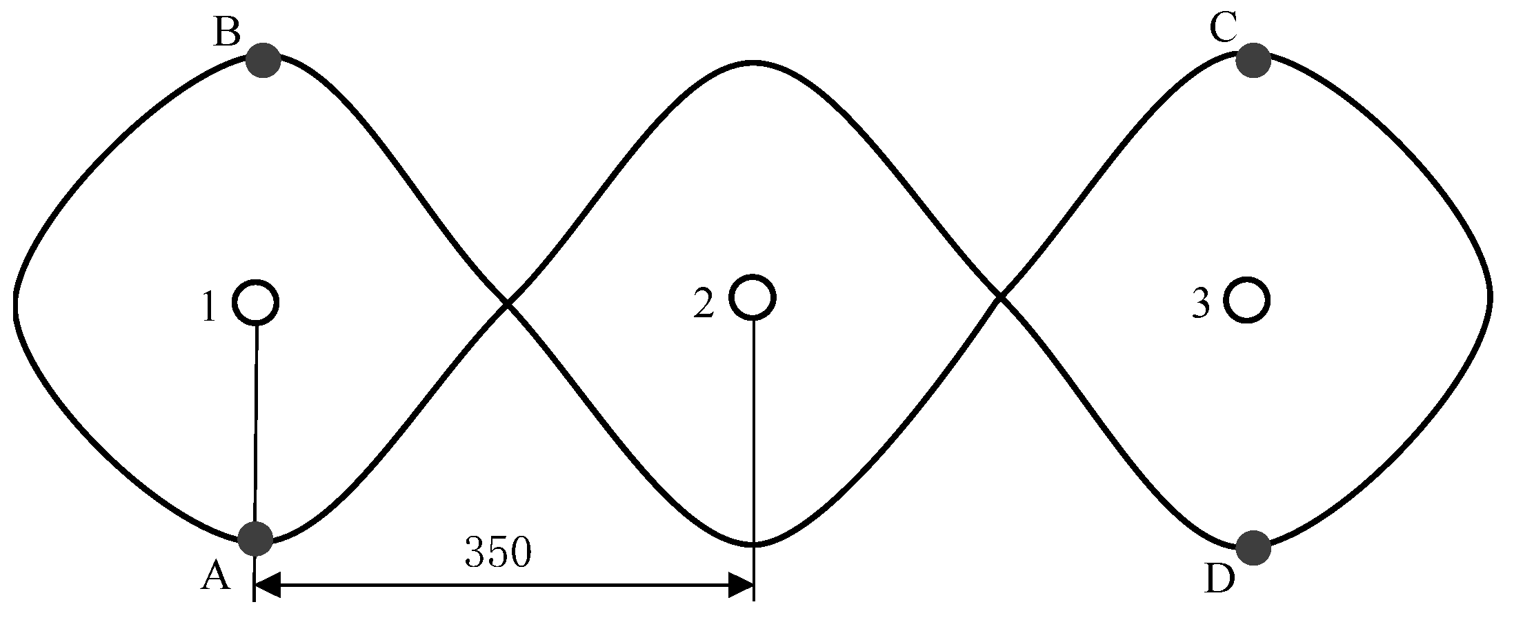
4.1. Running Track Analysis of the Carbon-Free Car

As shown in Figure 4, the double-8 track can be approximately combined into a cosine curve (the track between BC and AD) and a semicircle curve (arc AB and arc CD ). Arc AB is a semicircle with obstacle pile 1 as the center and 106 mm as the radius length, and the arc CD is a semicircle with obstacle pile 3 as the center and 106 mm as the radius length. To prevent the car from colliding with obstacles, the turning radius of the car shall not be less than 100 mm. To prevent sudden changes in the rotation angle of the front wheel of the car, it should be ensured that the semicircle arc and the cosine curve have the same radius of curvature at the junction.
When the plane of the car steering wheel (front wheel) is parallel to the plane of the rear wheel, the car goes straight ahead. When calculating the track length, take the center point of barrier pile 2 as the coordinate origin and the coordinate of point C as (350, 106), and the curve equation of BC is established as:
Y = a r c   c o s x L · 2 π
where A is the amplitude of the cosine curve, and L is the abscissa of the cosine curve in one cycle. Considering the distance between obstacles is 350 mm, the car’s width is 140 mm. Considering the influencing factors and the accumulated error during operation, the safety distance is set to 130 mm. Therefore, the track amplitude of the car = car width/2+ safety distance = 200 mm, and the length of one cycle is 1400 mm. The track equation is:
Y = 200   c o s π 700 x
The track length L2 of the driving wheel can be calculated by calculus:
L 2 = Y 2 + 1 d x
BC, AB and L2 are calculated by MATLAB CD 2022a: BC = 824.7 mm, AB = 106 π mm, L2 = 2 (BC+AB) = 2315.5 mm.

4.2. Cam Structure Design of the Carbon-Free Car

As mentioned above, the basic structure of the carbon-free car needs to be determined in advance, and then the cam mechanism is mainly designed to make the car run according to the specified track. Based on the control variable method, it is necessary to determine the front and rear axle distance A and the driving wheel offset eL in advance, as shown in Figure 5.
The relevant data on carbon-free cars from several colleges and universities that won the national first prize (as shown in Table 1) is used as the reference.
The front and rear axle distance A values of carbon-free cars in universities are mostly between 110 mm and 115 mm, and the values of eL are mostly between 65 mm and 75 mm. In this design, the carbon-free car A is designed to be 112.5 mm, eL is designed to be 70 mm, eL’ is designed to be 60 mm, and the rear wheel diameter is designed to be 120 mm. The offset distance of the driving wheel is greater than that of the driven wheel because the gear transmission mechanism is set on the side close to the driving wheel [15].
In this study, a design idea is put forward to deduce the cam stroke from the law of front wheel swing angle and then deduce the cam profile. The double-8 type track is a central symmetrical closed route, and the entire cam profile can be obtained by analyzing only half of the track. The overall idea is as follows: the cam is divided into N parts based on the angle, and the angle that the cam rotates is 360°/N each time, with corresponding forward distance LT (called step distance, we set the step distance to 0.000015 m in the simulation); set the initial coordinate of the carbon-free car point Q as (0, 0.1750 m) (Figure 6). In the initial state, the driving wheel is parallel to the straight line where the obstacle piles are located and face straight ahead. If the initial value of the front wheel swing angle, the initial value of the included angle of the straight line where the driving wheel and the obstacle pile are located (i.e., the body swing angle), the distance between the front axle and the rear axle, the driving wheel offset, the driving wheel step distance, and other parameters are known (Table 2), the next node coordinsates can be calculated, and the subsequent node coordinates can be calculated step by step through the iterative method. Finally, the point Q track can be obtained.
As shown in Figure 6, the arc from right to left represents the instantaneous track of the driving wheel, the instantaneous track of point Q, and the instantaneous track of the driven wheel. Known car parameters include the distance from the front wheel to rear axle A, driving wheel offset eL, driven wheel offset eL, and the forward distance of the driving wheel in each iteration (LT = houl). The curvature of point Q on the rear axle is:
ρ = tan θ/A
After each iteration, the forward distance of point Q, the forward distance of the driven wheel, and the forward distance of the front wheel are:
l = h o u l 1 + ρ · e L
l z = h o u l · 1 p · e L 1 + p · e L
l q = l c o s θ
The car body is parallel to the straight line where the obstacle piles are located when starting to enhance operability. The included angle between the car body and that straight line is assumed to be φ, as shown in Figure 7.
The position of the first obstacle pile is set as the coordinate origin (O), and the coordinates of each point, when the car is in the initial position, are: Q (0, 0.175 m), QZ (0, 0.175 meL), QC (0, 0.175 m + eL), and Qq (A, 0.175 m). The car travel track can be obtained through continuous iteration using the following formula. The iterative process is as follows:
Body swing angle φ:
φ1 = φ0 + l0·ρ0
φ2 = φ1 + l1·ρ1
φ3 = φ2 + l2·ρ2

φ(n+1) = φn + ln·ρn
Through iteration, the coordinate of the Q point corresponding to the body swing angle of the carbon-free car at each forward step is obtained:
x(n+1) = xn + ln·cos φn
y(n+1) = yn + ln·sin φn
Through iteration, the coordinate of the driven wheel corresponding to each forward step of the carbon-free car is obtained:
xc(n+1) = xcn + lcn·cos φn
yc(n+1) = ycn + lcn·sin φn
Through iteration, the coordinate of the driving wheel corresponding to each forward step of the carbon-free car is obtained:
xz(n+1) = xzn + lzn·cos φn
yz(n+1) = yzn + lzn·sin φn
Through iteration, the front wheel coordinate corresponding to each forward step of the carbon-free car is obtained:
xq(n+1) = xqn + lqn·cos (φn + θn)
yq(n+1) = yqn + lqn·sin (φn + θn)
At the initial stage of exploring the law, the car body structure specified above shall be driven down the track manually. To improve efficiency, the step distance can be appropriately increased. Record the front wheel swing angle at each step. Preliminarily explore the functional relationship between the swing angle θ and the number of steps. Draw the function curve according to the manually obtained coordinates (Figure 8 shows MATLAB’s front wheel swing angle curve based on manual exploration, which stipulates that the front wheel swing angle steering is left positive and right negative). The curve can be divided into four sections, BS1, S1S2, S2C, and CD. The number of nodes (the number of steps, the number of iterations) of the four segment curves is N1, N2, N3 and N4, respectively. The more nodes, the more accurate it is.
Among them:
BS1 segment is approximately a cosine function, and the expression is: θ1 = h + acost, and the initial value is (0, −0.615 m);
S1S2 segment is approximately a constant function, and the expression is: θ2 = ha;
S2C segment is approximately a cosine function, and the expression is: θ3 = hacost;
CD segment is approximately a cosine function with small amplitude, and the expression is: θ4 = h + a + bbcost.
Where, a is the amplitude of the sine curve of the simple harmonic function in the BS1 segment. Changing a will affect the maximum and minimum values of the cosine function, and then affect the left and right steering amplitude of the front wheels of the car; changing h will affect the position in the ordinate direction of the function curve, thus changing the front wheel swing angle of the car as a whole; changing b will affect the maximum and minimum values of the cosine function of the CD segment, and then affect the transition of the car from point C to point D.
The maximum swing angle obtained from the above curve is about 0.685. After the front wheel swing angle law is determined, according to Figure 9, the relationship between the push rod displacement and the front wheel swing angle is:
S = B·tanθ
where, S is the displacement of the push rod (that is, the difference between the current position of the push rod and the position when the front wheel swing angle is 0), and B is the vertical distance between the push rod and the front fork axis, which is a constant value. This design takes 30 mm. With the help of MATLAB, the displacement law of the push rod is obtained, as shown in Figure 10.
The maximum swing angle of the front wheel is 0.6850 < 0.5 π, so the displacement law of the push rod is positively related to the swing angle of the front wheel, and the change law of the two is the same. The running track of the car can be obtained based on MATLAB (Figure 11). Among them, the dotted line (outermost) is the track of the driving wheel, the solid line (middle) is the track of the front wheel, and the double dotted line (innermost) is the track of the driving wheel.
The above-related parameters (a, b, h, etc.) can be fine-tuned through MATLAB tools until the track meets the requirements of the competition. Through repeated adjustment, the ideal related parameters that meet the requirement are obtained: a = −0.65; b = 0.034; h = 0.035. Considering both efficiency and accuracy, the number of nodes of each front wheel angle curve is determined as: N1 = 26,338; N2 = 13,348; N3 = N1 = 26,338; N4 = 87,155 − (2N1 + N2).
After determining the function curve of the push rod displacement steps, the function curve of the cam push-rotation angle can be calculated, and then the cam profile can be obtained by the backward design method (Figure 12).
After the cam profile is determined, the transmission ratio i and the diameter of the rear wheel can be set according to the demand (since one cycle of cam rotation is the half-track, the ratio of half-track length to the circumference of the rear wheel is the transmission ratio). The size of the half-track in this design is 2315.5 mm. If the transmission ratio is 3.5, the rear wheel diameter is 211.7 mm. Adopt gear transmission, take modulus as 1, number of teeth z1 = 30, z2 = 105.

5. Discussion

The National College Students Engineering Training Comprehensive Ability Competition is a nationwide science and technology innovation practice activity for college students initiated by the Department of Higher Education under the Ministry of Education. It has three main purposes: talent training, improving the quality of education, and promoting entrepreneurship and employment. The competition is grounded in theory, focusing on innovation, highlighting abilities, and emphasizing practical skills. This process enables students to apply their theoretical knowledge in practical situations and develop critical thinking and problem-solving skills. Through this competition, students can identify their weaknesses and improve upon them, while also gaining a more realistic understanding of the subject beyond the classroom setting.
Previous competitions mainly involved simple trajectories like the 8-shaped and double 8-shaped, which could be achieved using the crank-link mechanism. The emergence of more complex trajectories since 2021 has increased attention on the cam mechanism. Therefore, there are few studies on this method. One of the aims of this study was to design the cam mechanism of a carbon-free car based on the reverse design method to make the car travel along complex trajectories. Little was found in the literature on applying reverse design methods to design carbon-free cars. The reverse design method proposed in this study provides a new idea for college students to design carbon-free cars. It can help them achieve better results in the game and stimulate their enthusiasm for mechanical learning. This method involves reversing the motion law of the push rod in the cam mechanism with the help of manual and software assistance and then reversing the cam profile accordingly. The resulting prototype has a low error rate and requires fewer adjustments in later stages. In contrast, the traditional forward design method relies heavily on the designer’s experience. It involves guesswork, often resulting in a prototype with a large error rate during the preliminary design phase.
In addition, it can promote the learning of related courses such as mechanical design and mechanical principles. The carbon-free car, designed using this method, can serve as a valuable case study in classrooms and even as a subject for course design. Using this method in designing a carbon-free car reduces the debugging workload and shortens the design cycle, ensuring completion within the specified time limit for the course design. This approach can not only fulfil the learning needs of students but also encourage their participation in competitions, thereby greatly increasing their enthusiasm for related courses.

6. Conclusions

For National College Students Engineering Training Comprehensive Ability Competition, this study proposed a carbon-free car design method based on the reverse design as an alternative to the forward design method, which has been criticized for its large deviation and high debugging workload described in detail the design idea of the carbon-free car based on the reverse design. The structural composition, force analysis and reverse methods of the carbon-free car were introduced emphatically. The other structures of the carbon-free car, except the cam steering mechanism, were solidified based on the ‘control variable method’, and the cam profile was designed according to the track based on the backward design. First, the relationship between the front wheel swing angle θ and the number of car steps was obtained, then the relationship between the displacement of the push rod and the number of steps was derived; second, the track curves of the front wheel, rear drive wheel and rear driven wheel were obtained by an iterative method; finally, the cam mechanism was designed after the cam profile curve was obtained. The whole process is simple and feasible. Each step has a clear purpose and strong operability, which provides a certain theoretical and technical support for the subsequent design of the carbon-free car. This method can extend to other application scenarios, such as trackless robots. It can make the robot drive along a predetermined trajectory and accomplish specific tasks.
It is worth noting that this method needs to be implemented after the parameters of the overall structure of the carbon-free car are determined. Then, will the difference in structure and component size affect the stability, precision and obstacle avoidance performance of the carbon-free car designed based on reverse design? This problem can be further studied to determine the optimal carbon-free trolley structure and the size of key components.

Author Contributions

Conceptualization, X.M. and H.Z.; methodology, H.Z.; software, X.M.; validation, H.L. and X.W.; formal analysis, X.M.; investigation, X.M.; resources, X.W.; data curation, X.M.; writing—original draft preparation, X.M.; writing—review and editing, X.W.; visualization, X.M.; supervision, X.W. and H.L.; project administration, X.W. and H.Z.; funding acquisition, X.W. and H.Z. All authors have read and agreed to the published version of the manuscript.

Funding

This research was funded by the First-Class Undergraduate Major Construction Project of Tarim University, grant number YLZYXJ202102, Tarim University Higher Education Teaching Reform Research Project, grant number TDGJYB2314 and the ‘Science and Education Integration, Industry-University Collaboration’ Agricultural Mechanization Postgraduate Teaching Team.

Institutional Review Board Statement

Not applicable.

Informed Consent Statement

Not applicable.

Data Availability Statement

Not applicable.

Acknowledgments

The authors sincerely thank the anonymous reviewers for their critical comments and suggestions for improving the manuscript.

Conflicts of Interest

The authors declare no conflict of interest.

References

  1. Liu, Y.F.; Xia, Y.L.; Liang, Z.H.; Chen, L.; Li, X.B. Track simulation and structural design of the double 8-typed carbon-free car based on MATLAB. J. Mach. Des. 2020, 37, 8–13. [Google Scholar]
  2. Wang, D.W.; Hou, J.H.; Guo, C.Y.; Shen, X.P.; Zhu, Y.P. Design of double 8-typed obstacle-avoiding carbonless car based on the RSSR mechanism. J. Mach. Des. 2020, 37, 20–26. [Google Scholar]
  3. Han, S.K.; Jie, M.Y.; Lin, C.X.; Zhang, S.J. The Key Structure Design and System of “Double 8 -Shaped” Trajectory Carbon-Free Car. Mach. Des. Manuf. 2019, 43, 60–64. [Google Scholar]
  4. Zeng, D.H.; Zhang, D. Double 8-shaped carbon-free car based on cam control. Machinery 2020, 58, 58–62. [Google Scholar]
  5. Zhang, K.Q.; Xiu, F.Y.; Zhang, Y.; Su, L.; Yang, X.J. Design of double 8-shaped trajectory carbon-free car based on cam mechanism. J. Mach. Des. 2020, 37, 24–28. [Google Scholar]
  6. He, R.H.; Xiao, J.C.; Du, K.Q.; Yue, J.H.; Lan, M.H. Structural Design and Analysis of S-Ring Carbon-Free Cars. J. Mach. Des. 2023, 40, 48–54. [Google Scholar]
  7. Li, J. Universal Design Method of Carbon-free Car Based on 3D Motion Simulation. Mach. Des. Res. 2022, 38, 46–48+52. [Google Scholar]
  8. Huang, H.L.; Zhu, H. Design of carbon-free car on S-shaped circular track based on cam mechanism. Exp. Technol. Manag. 2023, 40, 136–140. [Google Scholar]
  9. Sun, G.X.; Zhou, X.S.; Qiao, G.B.; Xu, Z.R. CAM mechanism and its design method for the “double 8” trajectory. J. Mach. Des. 2019, 36, 30–35. [Google Scholar]
  10. Zhong, Z.R.; Wan, J.G.; Zhu, W.H. Error Analysis and Optimization for Carbon-Free Car. Mach. Des. Manuf. 2022, 380, 246–250. [Google Scholar]
  11. Xu, H.Z.; Jiao, H.B.; Liu, J.D.; Niu, Z.H. Reverse design and analysis of gear five-bar planting mechanism based on agronomic requirement. Pak. J. Agric. Sci. 2022, 59, 329–337. [Google Scholar]
  12. Zhang, Y.L.; Tian, S.; Yao, Y.F. The Structural Design and Trajectory Analysis of Double “8” Carbon-free Dolly. J. Xi’an Univ. (Nat. Sci. Ed.) 2020, 23, 24–29. [Google Scholar]
  13. Ai, X.J.; Wang, C.H.; Su, L.; Zhao, L.M. Design for Gravity-Driven and Direction-Control Carbon-Free Vehicle. Mach. Des. Manuf. 2016, 54, 157–160. [Google Scholar]
  14. Wang, X.N.; Zhou, H. Design and Simulation of carbon-free car with double 8-shaped track. Intern. Combust. Engine Parts 2019, 118–121. [Google Scholar]
  15. Zhou, C.; Gao, K.S.; Ju, C.M.; Zhang, Y.L. Dynamic Simulation of Carbon-Free Caron ADAMS. Mach. Des. Manuf. 2015, 8, 197–199+205. [Google Scholar]
Figure 1. The schematic diagram of a carbon-free car: (a) Front view; (b) Vertical view; (c) Virtual prototype of a carbon-free car (case). Note: 1. Thin wire; 2. Pulley mechanism; 3. Weight; 4. Column; 5. Cam; 6. Swing rod; 7. Front-wheel (steering wheel); 8. Gear transmission mechanism; 9. Drive wheel; 10. Spool; 11. Base plate; 12. Driven wheel.
Applsci 13 08829 g001
Figure 2. Main components and common implementation mechanisms of the carbon-free car.
Applsci 13 08829 g002
Figure 3. Overall force analysis of the carbon-free car.
Applsci 13 08829 g003
Figure 4. Schematic diagram of carbon-free car track.
Applsci 13 08829 g004
Figure 5. Schematic diagram of body structure.
Applsci 13 08829 g005
Figure 6. Schematic diagram of the front wheel swing angle.
Applsci 13 08829 g006
Figure 7. Schematic diagram of the body swing angle.
Applsci 13 08829 g007
Figure 8. Swing angle law of front wheel.
Applsci 13 08829 g008
Figure 9. Schematic diagram of push rod displacement. Note: 1. Front fork shaft; 2. Push rod; 3. Chute; 4. Rocker.
Applsci 13 08829 g009
Figure 10. Function curve of push rod displacement-step number.
Applsci 13 08829 g010
Figure 11. Track simulation of carbon-free car.
Applsci 13 08829 g011
Figure 12. Cam profile.
Applsci 13 08829 g012
Table 1. Key structural parameters of several typical carbon-free cars.
UniversityDistance between Front and Rear Axles A/mmDriving Wheel Offset eL/mm
Jiangsu University111.568
Northeast Forestry University11573
Shenyang Agricultural University113.567
Changchun University of Technology11371
Taiyuan University of Technology11265
Table 2. Parameters required for iterative calculation.
Key Parameters of the Carbon-Free CarSymbol
Front-wheel swing angleθ
Body swing angleφ
Distance between front and rear axlesA
Driving wheel offseteL
Driven wheel offseteL
Distance between nodes (Step distance)LT
Disclaimer/Publisher’s Note: The statements, opinions and data contained in all publications are solely those of the individual author(s) and contributor(s) and not of MDPI and/or the editor(s). MDPI and/or the editor(s) disclaim responsibility for any injury to people or property resulting from any ideas, methods, instructions or products referred to in the content.

