1. Introduction
The Advanced Metering Infrastructure (AMI) plays a pivotal role in modernizing traditional power distribution systems by enabling bidirectional communication and data exchange between utility providers and end-users. This transformation is a critical element of the Smart Electrical Grid, enhancing energy efficiency and grid reliability and enabling the integration of renewable energy sources. However, with an increasing reliance on interconnected digital technologies, the AMI system also becomes vulnerable to various cyber threats, making robust security management an indispensable aspect of its successful implementation [
1].
The fundamental objective of an AMI system is to collect real-time data from Smart Meters (SMs) installed at consumer premises and communicate this information back to utility companies for billing, load balancing, and demand response purposes. The data transmitted through the AMI system include sensitive information about energy consumption patterns, user behavior, and potentially private details of consumers. Consequently, the confidentiality and integrity of these data are paramount to protecting the privacy and security of consumers and maintaining the overall stability of the electrical grid [
1,
2].
To safeguard the AMI system against potential cyber-attacks, it is essential to establish a comprehensive and robust Security Management framework. The Security Management approach for AMI should encompass various aspects, including but not limited to authentication, access control, encryption, and key management. In this paper, we focus on discussing the modeling of Security Management for the Advanced Metering Infrastructure (AMI) system of Smart Electrical Grids with specific emphasis on the Key Management Scheme (KMS) that is designed to address the unique security challenges of AMI [
3].
Security considerations for AMI differ significantly from conventional IT systems due to several distinct features. First, Smart Meters (SMs) often have limited storage and computational capabilities, necessitating the development of lightweight cryptographic techniques to ensure secure key generation, distribution, and management. Second, the AMI system employs a hybrid message transmission approach that combines unicast, broadcast, and multicast modes, introducing complexities when managing encryption keys effectively. Finally, the participation of consumers in Demand Response (DR) projects can vary over time, demanding flexible key refreshing policies to accommodate changes in the AMI ecosystem [
4].
SMs are a major component of modern smart grids (SG). Since SMs have limited computation power and are positioned at an exceedingly long distance from the utility, Advanced Metering Infrastructure (AMI) is an essential component in the SG that represents the structure of a complex communication network. It integrates SMs, Monitoring Systems (MS), sensing devices, and the Meter Data Management System (MDMS) [
1]. Through AMI, utilities can congregate their fundamental targets for revenue protection and load management. AMI gathers instantaneous information about individual and aggregated demand, puts caps on consumption, and performs various revenue models to control their costs. The application of AMI in the SG enables greater control and operation with smaller margins. This scheme requires a sort of communication and coordination between the different components of the power grid. For years, data exchanged in traditional power line communications were only electrical system measurements, such as voltage measurements, and these data were not considered to be as valuable as financial information [
2,
3]. However, with the changing paradigms in modern power system operations, financial information is currently exchanged in power system communications for the purpose of deregulated energy markets. In these energy markets, a small error in the power information (both electrical and financial) can lead to a disruption in the bids of highly competitive electricity markets. This raised the likelihood of cyber security issues and necessitated the integration of security protocols within SG for comprehensive security functionality [
4,
5]. SG’s evolution to a cyber-physical system by deploying AMI makes it prone to cyber threats aside from SCADA vulnerabilities. AMI cyber security, from an oriented threat perspective, impacts data confidentiality, integrity, availability, and accountability [
6]. The most crucial security issues that must be resolved before AMI can be deployed are message confidentiality for user privacy and behavior, message authentication for meter readings (DR), and load control communications. Using encryption and authentication methods that rely on the safety of cryptographic keys can resolve confidentiality and integrity difficulties. In AMI systems, key management for several devices is essential for security. The key management scheme consists of a key organizational structure, key generation, updating, distribution, storage laws, etc. (KMS). Recently, a number of studies on the key management of AMI systems were released. An example of a complete system for secure AMI communications, including secrecy and authentication, is presented in [
7]. Using mutual authentications, this system can provide trust services, data privacy, and integrity. A survey on key management and authentication approaches in smart metering systems is presented in [
8], including security measures like the Advanced Encryption Standard (AES) [
8], encryption, and public-key infrastructure authentication.
The focus of this paper is on-device authentication, data secrecy, and message authentication mechanisms for Advanced Metering Infrastructure (AMI) applications. The outcomes have effects on key management. There is not a complete solution yet for managing keys in AMI systems for various smart devices. If the AMI network is constructed on a wireless sensor network, the authors in [
9] propose a key establishment and security technique based on public-key cryptography. Depending on the stage of smart grid development in various nations, different AMI network types exist [
10,
11]. The significance of key management for a large number of devices in AMI is important for the security preservation of cryptographic keys [
12]. Moreover, a few KMSs have been set up to enable secure communication between SCADA systems and wide-area protection systems: two examples of power control systems [
13,
14]. However, because of the differences in these systems’ architectures, message characteristics, and needs, these KMSs, along with those utilized in general IT systems, have difficulty when immediately adapted to an AMI system.
We may infer from the findings of the available study that the suggested KMSs are for a certain AMI system. When application functions, communications, and information technology change, the KMS can no longer be appropriate. However, the majority of AMI systems have still been in the experimental stage until recently; therefore, the future is still unknown. Additionally, there are regional and national differences in the design and development of an AMI system. The functionalities that must be deployed are different from the standpoint of the application’s needs. The applications are quite straightforward, like metering, measuring, and monitoring; the other applications are overly complicated and focus on DR and load management applications. According to the needs of the program and user desire, there are several communication options as well.
Due to these aforementioned issues, we are attempting to recommend a more widespread KMS for AMI systems. To summarize AMI’s characteristics and development, we believe that its structure and constituent parts are stable. In other words, key management’s primary, ongoing goal is securing SMs. In order to manage the keys of several SMs, a key management framework based on a key graph is suggested. Although the AMI’s functions are not set in stone, we can create a KMS to hold all of the potential functions. In practice, users can select a portion of the KMS for particular applications. Although the properties of messages sent through communication channels can be determined by the function needed, communications are also not fixed. To address this issue of managing keys for multiple smart devices in AMI systems, this research proposes three different key management methods for broadcast, unicast, and multicast communications, which are designed based on functional requirements and message types. Each of these methods includes specific procedures for key regeneration and refreshing, considering factors such as the computation and storage limitations of SMs, the time requirements of functions, and other relevant factors.
The remaining sections of this paper are arranged as follows:
Section 2 examines the framework and also the message flow for an AMI system. KMS design difficulties with the AMI system are introduced in
Section 3.
Section 4 represents the KMS design difficulties with an AMI system. The key management and key refreshing policy for unicast, broadcast and multicast communication is discussed in
Section 5,
Section 6 and
Section 7, respectively.
Section 8 introduces the security examination. In
Section 9, the performance analysis in terms of the cost of storage, the time cost for computation, and the time cost for distributions are discussed. In
Section 10, a conclusion is introduced.
2. Advanced Metering Infrastructure (AMI) Features
This section presents the AMI’s main features, including the framework and the interconnection messages.
2.1. Framework of AMI System
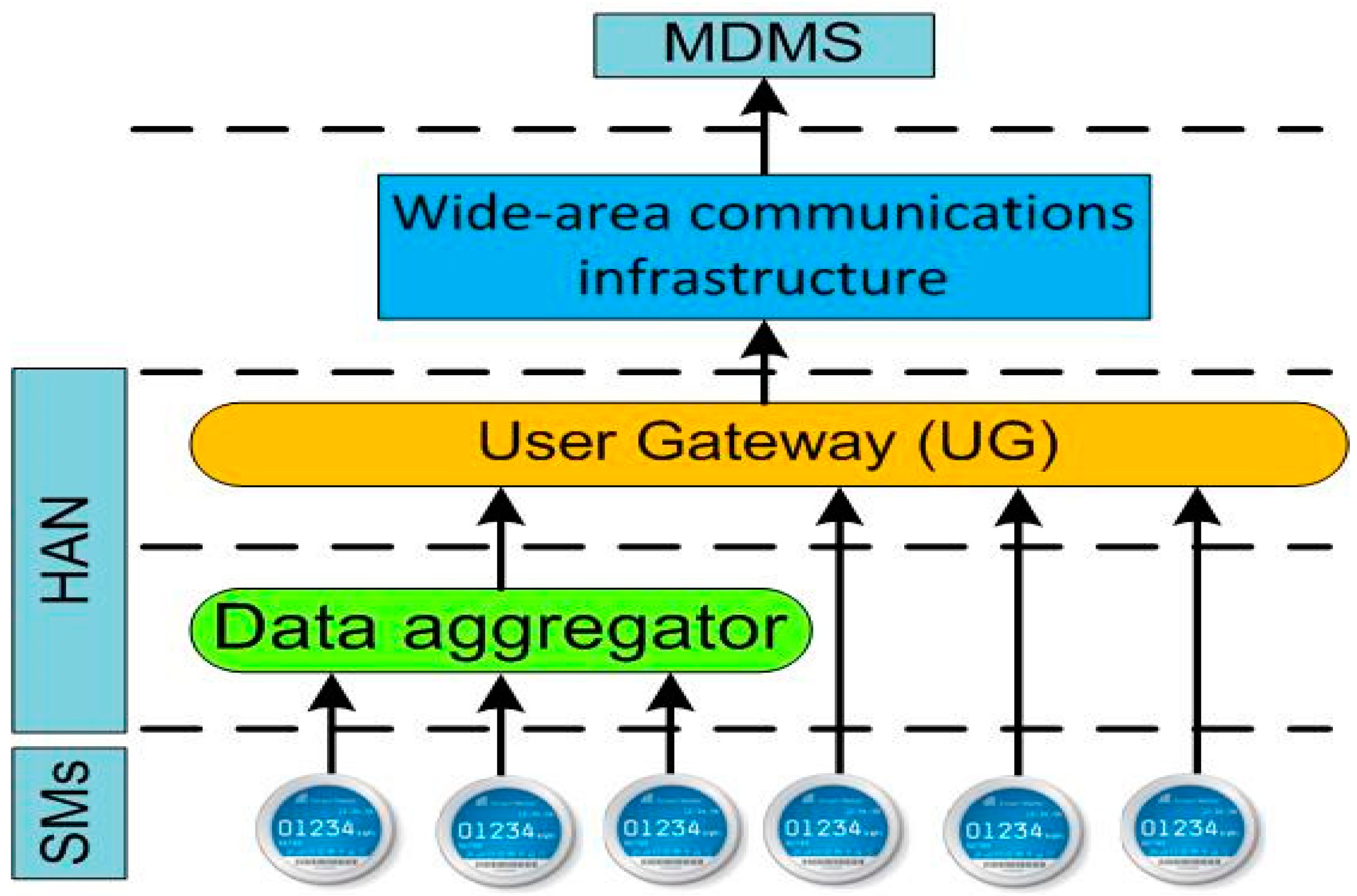
As shown in
Figure 1, the AMI system consists of various technologies and applications that combine to function as a single entity. These technologies are SMs, user gateways (UGs), wide-area communication infrastructure, and Meter Data Management Systems (MDMSs). Brief descriptions of these technologies are mentioned below:
SMs: SM is a programmable solid-state device that can perform a variety of functions, including Bi-directional metering, including the real-time monitoring of power consumption, peak demand, voltage, current, frequency, and power factor. They can support net metering, transmit notifications of power outages or restoration, monitor power quality, permit remote turn-on or turn-off operations, and assist with time-based pricing. They can also give consumption statistics for both consumers and utilities. Additionally, they can help with (DR) goals [
15], which enable greater energy efficiency because information feedback has been demonstrated to decrease customer consumption [
16].
UGs: The Universal Gateway (UG) is responsible for performing protocol switching and facilitating communication between two different networks, such as the wide area network and the in-home network. This function is typically conducted by other devices, like SMs or personal computers (Pcs).
HANs: A Home Area Network (HAN) is a specific type of local area network that connects to Distributed Energy Resources (DERs), local control devices, SMs, and the (UG) [
16,
17].
Wide-area communications infrastructure: They support continuous contact between the utility, customer, and the controlled electrical load. It has stringent privacy restrictions while using open, two-way communication protocols. One popular architectural [
18] feature is the use of local aggregators to compile data from collections of meters SMs and send them to a central server. Radiofrequency, optical fiber, the power line carrier, the Internet…etc., may all be considered for use in providing any or this entire infrastructure.
Meter Data Management System (MDMS): MDMS is a database of meter data that includes analytical capabilities and is connected to the user side through an AMI head end. It communicates with other electric power utility systems, such as customer information systems, outage management systems, distribution management systems, and so on, through enterprise buses.
2.2. Interconnection Messages in AMI System
Over AMI communication networks, interactive messages are sent and received between smart grid devices. These messages include topics such as electricity pricing, remote load management, meter data, notifications for power outages and returns, publishing DR projects, subscribing to or canceling DR projects, and more. There are two components involved in the sending and receiving of these communications. The first one is user-level devices (SMs, UGs, etc.) which are the sending components. To keep things short, we refer to these devices as NXs. The other component is the data management system (DMS) which aids in the transmission and reception of AMI data.
Messages may be categorized as either unicast, broadcast, or multicast. The unicast message is sent from DMS to NX, but broadcast messages are sent to all NXs, whereas multicast messages are sent to DMS and a subset of NXs participating in the same DR project.
Table 1 details the types of messages, along with their respective senders, recipients, and modes of transmission [
19]. This table also includes the time requirements for various message types based on the requirements of the State Grid Corporation of China. Even though these time estimates are not identical in every country, their variances are negligible when considering the global smart grid’s overall development goal.
3. A KMS Design Challenge with AMI System
The standard components of any KMS may include key management frameworks, key generation and refreshment rules, key distribution policies, and key storage techniques. Conclusions about the challenges of creating the KMS may be drawn from the AMI’s structure and messaging as follows:
Hybrid transmission techniques are utilized in bidirectional communications, such as broadcast, unicast, and multicast. It is expected that the KMS will be able to accommodate all of these transmission modalities. In order to find a solution to this issue, the KMS must be adaptable enough to accommodate all three distinct forms of transmission. The protocols governing the production, updating, and distribution of keys are each crafted specifically for each mode.
The NXs are usually implemented using embedded systems. When compared to a typical computer or server, they are less powerful both computationally and in terms of storage. Additionally, the messages call for limited-time broadcasts. The key generation and refreshing algorithms are most significantly impacted by NXs’ low computational capabilities. Primarily, quite simple cryptographic methods like hashing might be utilized. Additionally, the frequency of key distribution should be kept to a minimum because of the restricted time for message delivery. Similarly, it is best to reduce the number of keys and other relevant data that must be saved in NXs.
Projects using DR users do not have fixed users. Depending on their preferences and needs, they may choose projects at various periods. Users who participate in the same DR project may band together to establish groups; these users are known as group members.
Due to the dynamic nature of group participation in DR projects, ensuring both forward and backward security in the multicast mode becomes critical. New users should be assigned to groups when they join the project, and each group member should receive new keys and additional data to ensure secure communication. While users who leave the project no longer receive updates, shared keys, and additional data should be refreshed frequently to preserve security.
4. Key Management Framework (KMF)
In this section, the definitions, common abbreviations, and KMS for the AMI system are explained. Abbreviations specifies a set of abbreviations and their meanings for use in the KMS.
Based on the key graph concept [
20], an AMI system’s key management architecture is created. This is conducted in order to manage all three distinct forms of message transmission. As shown in
Figure 2, KMF can be defined as:
where:
This is a set that is finite and non-empty and represents NXs within the AMI system.
. This is a set that is finite and non-empty, where {k1, k2, …, kn} represents the keys of NXs. {gk1, gk2, …, gkm}. “k” represents the group keys of demand response projects, and “k0” is the root key of the key hierarchy.
R: The user–key relation is a binary relation between U and K, denoted as Rk ⊂ U × K. It indicates that user u knows key k if and only if (u, k) is present in R.
In addition to this, a function is connected to the set, and its definition is as follows in (2):
For example, of the AMI, the KMF shown in
Figure 3 might be expressed in (3), (4), and (5), for instance:
The set user set identifies the users involved in DR project 1, while the users participating in DR project 2 are denoted by the set user set (. For the broadcast mode, the KMF uses the group keys, and the root key k0. are the keys for the multicast mode in several DR project groups for each MS and each SX in unicast mode. The core of key management is these keys, so it is important to outline the procedures for their creation, distribution, and periodic refreshment. In addition, in order to authenticate and verify messages, as well as encrypt and decrypt them, session keys are required throughout the communication process. As a result, the procedures used to create, distribute, and renew session keys must be carefully designed while considering the amount of traffic on the network and the computing power of SXs.
In order to provide a concise introduction to the KMS, the MS is denoted by the symbol
. First, the keys of KMF and the extra value for creating session keys are created by
via the use of certain key servers. After that, the keys are disseminated to SXs. The initialization procedure is shown in
Figure 4, which is then followed by explanations in further depth.
The user keys as well as the relevant extra numbers are transmitted to “”, respectively, using safe ways. Additionally, the root key and the extra value are dispersed among “.” The keys “” and the accompanying supplementary values “” are distributed among SXs in accordance with the users’ involvement preferences in DR projects. These preferences are reflected in the GCount values.
5. Unicast Communication
This section presents the key management and key refreshing policy for unicast communication.
5.1. Key Management for Unicast Communication
Messages in AMI systems were analyzed, and the results revealed that the unicast transmission method comprises three distinct kinds of messages: the remote load control, meter data, and subscription to or cancellation of DR projects. The messages may proceed either way, from the MS to the SX or from the SX to the MS. It is essential that both the secrecy and the integrity of the communications are maintained throughout the process of communication. In order to accomplish this goal, the session key has to be reset at the beginning of each session.
There are three distinct groups into which the key management steps for unicast communication can be divided. The phases for the unicasting communication method are shown in
Figure 5.
An initial session key generation is required. The session key ski is built in Steps 1.1 and 1.2 using the metering data Mi, the metering date CDATE, the value Counti, and the user key ki. In Step 1.3 and Step 1.4, upcoming information for sharing is encrypted and signed using this session key before it is sent. In step 2, the data that have been encrypted together with the signature value are sent to the recipient. In step 3, the receiver is able to obtain the components that are required to produce the session key. Step 3.1 and Step 3.2 are responsible for the generation of the session key ski. It is possible to decode the data and verify the signature using the session key provided. Step 3.3 and Step 3.4 are responsible for verifying the signature between the transmitter and receiver before extracting the data using the decryption function (DE).
Figure 6 shows the flowchart for the unicasting communication process.
5.2. Key Refreshing Policy for Unicast Communication
It is recommended that the user key should be renewed at set intervals, such as once every day, once per week, and so on, to ensure that the key is always in its most up-to-date state. If you decide to utilize a HASH function as the key refreshing technique, in addition to lowering the price of key distribution in the network, you can guarantee independence between the new and old keys. Before each session, the session keys ought to be regenerated so that the confidentiality of the information can be maintained. Because there are so many SXs, the process of refreshing the session keys in the MS and then distributing them might result in a significant increase in the cost of the network traffic. On the other hand, this problem can be resolved if they are appropriately updated in both MS and SX in accordance with the chosen method.
If they were able to be appropriately refreshed in both MS and SX in accordance with a predetermined plan, this issue would not arise. The fact that part of the data that are utilized for key refreshing may be readily acquired by either side is the most significant aspect of the agreed-upon technique. As a result of our research, we discovered that the SX and MS were able to obtain the daily metering data of an electrical customer. This is due to the fact that metering is an essential feature of AMI systems. This has led to the creation of a unique session key refreshing approach that is based on metering data. The renewing rules for keys and variables in unicast communication are listed in
Table 2.
6. Broadcast Communication
This section presents the key management and key refreshing policy for broadcast communication.
6.1. Key Management for Broadcast Communication
The publishing of DR projects and information on energy prices are both messages that may be delivered using the broadcasting technique in order to ensure the message’s secrecy and authenticity; the session keys must be updated before each broadcast session. The three stages of detailed key management for broadcast communication are depicted in
Figure 7.
The variables Count0 and the root key k0 are used in Step 1.1 and Step 1.2 to produce the session key sk0. The information for transfer is encrypted and signed using this session key before being sent in steps 1.3 and 1.4. In step 2, the data that have been encrypted together with the signature value are then sent to all the recipients of SXs. Step 3.1 and Step 3.2 generate the session key at the recipients then Step 3.3 calculates the receiver signature. In Step 3.4, the recipients compare the transmitter signature and recipient signature, if there are equal, and the information is decrypted.
6.2. Key Refreshing Policy for Broadcast Communication
The key refreshing policy for unicast communication and broadcast communication are almost identical. This is because both types of communication use the same key. It is recommended that k
0 be updated at regular intervals, such as once per day or once per month, to maintain its validity. If a HASH function is employed, the key independence between new and old keys would perform admirably. Both new and old keys would be affected by this. Before each session, the broadcast communication session key sk
0 has to have its cache cleared. In addition, the implementation of the HASH function and routine k
0 and C
0 resets would be an excellent way to secure the independence of session keys as well as their unpredictability. The renewing of rules for keys and variables in broadcast communications is listed in
Table 3.
7. Multicast Communication
This section presents the key management and key refreshing policy for multicast communication.
7.1. Key Management for Multicast Communication
The multicast mode is an option for the transmission of electrical price information as well as remote load control in all different kinds of AMI messages The users who subscribe to a DR project are not permanently set; hence, the group’s members that are designated to receive multicast messages should be updated at regular intervals (for example, once every day or once every week) in accordance with the current state of the electric power utilities. As a result, the key management for multicast communication has been split up into two distinct pieces. The first is comparable to a broadcast communication’s key. Additionally, each new session must begin with the production of the multicast communication session key. The group key and extra value should be generated and updated with the help of unicast communication for the second key, taking into mind that users might participate in or withdraw from a DR project.
The generation and use of session keys within a DR project group are quite similar to broadcast communication. The main factor that distinguishes the receivers is their range. The process for generating a session key is shown in
Figure 8.
It is necessary to generate a session key initially. In steps 1.1 and step 1.2, the value GCountj is used to determine the group key gkj, which is used to generate the session key gskj. The information for transfer is encrypted and signed using this session key before it is sent in Steps 1.3 and 1.4. The receipts of DR project j receive data that have been encrypted together with the signature value. In step 3.1 and step 3.2, the receipts in the DR project regenerate the session key gskj. It is possible to decode the data and verify the signature using the session key provided in Step 3.3 and step 3.4.
When a user makes the decision to participate in or withdraw from a DR project, the user is responsible for sending a message to u0. After receiving the acknowledgment, the group key is updated.
Figure 8 is an illustration of the procedure as a whole. The implementation of this sub-process makes use of unicast messages. The information includes a total of seven steps, as shown in
Figure 9.
Step 1 is responsible for encrypting and signing the requested information. The request message is sent to u0 in step 2. After receiving the request from the user in step 3, the u0 must first decrypt and validate the request before examining it to decide whether it is a request to subscribe to project j or to exit the project. When the user requests to leave the project, DR projects could be incompatible, and the user must abandon the one they are currently working on in order to subscribe to the new one.
In step 4, the u0 response to the user’s request and creates a new key for the group, as well as an additional value in step 5. In step 6, the u0 transmit response sends a message to the user. Step 7 is responsible for notifying the user that the request was sent to the DR project and is responsible for determining whether or not it was successful.
In the case that certain people join or leave the DR project, it is important to regenerate the group key in addition to the extra value before the update time.
Figure 10 depicts steps 8 through 10 for regenerating and dispersing the new group key with an additional value. Step 8 prepares to distribute the modified group key and the added value to each DR project j member. The new group key and additional value are distributed in Step 9 to every single person in the DR project j community. In step 10, the user utilizes the new session key.
7.2. Key Refreshing Policy for Multi Communication
The key refreshing policy for unicast communication and broadcast communication are almost identical. Whether or not the users of the DR project change is determined by how the key refreshing policy is executed. If the users do not alter, the gkj, GCountj GCj, and gskjupdating procedures are comparable to the broadcast communication procedure from which the data are provided in
Table 4. However, when users join or leave a DR project, u0 needs to regenerate gkj and GCountj and distribute them to all users in the project. The data for this process are listed in
Table 5.
8. Security Examination
A secure random key generation process using b bits is used to create both a user key and a group key. A user key or a group key is used as a starting point for the generation of a session key, which is then combined with another value and hashed. The user key provides a safe environment. The extra value, which is generated by feeding a random integer into a HASH function, is completely arbitrary and unrelated to anything else. Since this is the case, the session key is likewise safe.
The user key may be automatically updated at certain intervals inside the KMS. The number of users who are leaving or joining the DR project determines whether or not the group keys need to be refreshed. In the case that a user wants to join or leave the DR project at the time of the update, the group key must be reset.
When it comes to refreshing techniques, the HASH function is used for both the user key and the session key. The session key differs from other keys in that it can be updated using either a random additional value or metering information together with the metering date. As a direct consequence of this, the new keys function independently of the old ones.
Only the two endpoints of the communication channel have access to the session keys. The receiver first uses a secure session key to validate the digital signature associated with the encrypted material. The communication is only decrypted by the recipient if it is successful in passing authentication. In such a case, the message is deleted without being read. After this, the authenticity of the information transfer as well as its integrity is guaranteed.
Considering that people have the option to either join or leave the group that is working on the DR project, it is important to think about the group’s forward and backward security. The group keys and other values are all generated and refreshed in accordance with our strategy if any user decides to join or leave the group before being sent to the new group’s members. This process only takes place if there are users who make either of these decisions.
9. Performance Analysis and Results
It is necessary to store the relevant data in order to make use of the KMS. These data should include a variety of keys, counters, and other values. The information that needs to be kept in MS and SXs is outlined in
Table 6. In
Table 7, the calculation techniques for the storage cost of the communication endpoints are provided. These approaches are based on the information in
Table 6.
The length of the key used in symmetric cryptography methods typically ranges between 128 and 256 bytes in real-world applications (such as AES and IDEA). In this particular piece of research, we chose a key that was 128 bits long, with a counter that was the same length and an extra value. For MS, the storage of keys and the data associated with them can be managed by specialized key management servers. There is no issue with the expense of storage.
In contrast, SXs have a restricted capacity for storing data. As a result, it is necessary to determine the storage cost that is the absolute maximum and achievable for each SX in accordance with the number of SX and the number of DR projects.
Table 8, which is derived from
Table 6, summarizes the storage cost according to the number of DR projects and SXs.
Figure 11 shows the relation between the number of DR projects and the storage cost in Kbytes. From this figure, it is shown that when the number of DR projects increases, the storage cost also increases.
As a result of this, we have determined that the storage cost incurred by each SX inside the AMI system would not rise as the number of SXs increased. Only an increase in the total number of DR projects would result in an increase in the storage cost for each SX. We assumed that the number of DR projects did not exceed fifteen and that each SX’s maximum related storage cost was 1.088 KB when everything operated as it should. The outcome might be considered satisfactory.
9.1. The Time Required for Conducting Computations
Because the transmission of messages has a time constraint, it is necessary to investigate the amount of time required to complete the maximum number of calculation jobs within a certain period of time. In accordance with the procedures of the key management, the following is an overview of the calculation technique for computing time costs for each of the three ways of transmission, which can be found in
Table 9.
Embedded systems are always used to conduct the implementation of the SX. To perform computations involving cryptography, embedded cipher chips are often used. Hash functions, symmetric cryptographic methods, and HMAC all have an approximate operating rate in the range of 10–50 Mb/s. An XOR operation has an extremely low throughput, making it impossible to take it into account.
The time investment required for computing in each SX can be tallied.
Table 10 presents an overview of the results. According to the results, the amount of time consumed on the calculation in each SX was extremely limited for SXs that did not have an effect on the transmission of various messages.
The PCI cryptographic coprocessor could be used to help with the calculation in MS. Symmetric cryptographic techniques, hash functions, and HMAC operate at a pace of between 50 Mb/s and 1 Gb/s, while the rate of random number generation was 1 Gb/s. The speed of an XOR operation need not be taken into consideration.
Table 11 contains the results of calculations that were performed to calculate the computation time cost for broadcast and unicast modes. The results indicate that the time cost was incredibly low and practically had no effect on the numerous messages being transmitted because it was so minutely high.
The value of NP and NG should be considered while determining the time cost for the multicast mode. The results of this calculation can be seen in
Table 12. The amount of time consumed increases according to the value of the NG. However, the time cost does not have any effect on the transmission of messages, even if NG is set to a value of ten thousand. The value of Np changed from 5 to 15, and the time consumed did not have any effect.
Figure 12 shows the relation between the total number of users in DR projects and the time cost of the computation. It is shown that when the number of users increased, the time cost of computation increased. It is also shown that when the number of projects changed from 5, 10, and 15, however, the time cost of computation did not change. Thus, the time cost of computations depended on the number of users, not the number of DR projects.
9.2. Time Cost for Distribution
The time needed to distribute keys during a refreshing period is calculated based on the key management study by multiplying NG (the total number of users in DR projects with users joining or exiting) by CT (the time needed to distribute a package containing the key and related data). The distribution package size for the key and data typically did not exceed 384 bytes. Typically, the Synchronous Digital Hierarchy (SDH) network based on optical fibers was used to transmit data at a rate of 155 Mb/s, 622 Mb/s, or higher between the MS and AMI systems.
Table 13 can be used to calculate the cost of this distribution. The results suggest that the distribution time does not affect the key refreshment process or network traffic distribution in AMI systems.
Figure 13 shows the relationship between the total number of users in DR projects and the time cost of key distribution and associated data. It is shown that when the number of users increased, the time cost of the key distribution increased.
10. Conclusions
The AMI is one of the most important elements in the smart grid, and therefore, it was necessary to take care of the confidentiality of the transfer of information from it to monitoring and control centers. A new KMS that addresses common security concerns has been developed in order to overcome the primary problems with controlling and monitoring AMI systems. Three essential management techniques are supported by the KMS design for unicast, broadcast, and multicast modes of hybrid transmission.
The storing and computation of keys and associated data can be simply implemented in SMs or UGs based on our system’s performance and security evaluations. Additionally, in an AMI system, the distribution of keys and the data they are connected with do not obstruct normal network activity.
After implementing the proposed strategy in our paper, the results were improved and indicated the stability of the AMI system and the security of the data. The storage cost was calculated according to the number of DR projects and SXs. The time required for conducting computations and the time cost for key distribution were calculated. The storage cost ranged from 0.448 to 1.4 Kbytes as the number of DR projects ranged from 5 to 20, which indicated that the storage cost increased when the DR increased. These values of storage cost are insignificant when compared with their improvement in storage devices.
The time required for conducting computations was calculated for three transmission ways and for each SX and MS. The proposed key management algorithm consumed about 5 to 38 microseconds at each SX and consumed 0.3 to 5 microseconds at MS with unicast and broadcast transmission ways. The time consumed in MS for multicast should take NG and NP into consideration.
The time cost for key distribution depends on the number of users in the DR project. Therefore, with 1000 users, the distribution time would be about 2.48 ms, and for 10,000 users, the distribution time would be about 24.77 ms.
In future work, the energy-efficiency could be studied, and research could be conducted on energy-efficient cryptographic algorithms to minimize their impact on performance and battery life. Additionally, Real-World Deployment and Testing could be applied to evaluate its effectiveness in actual AMI systems. This could help identify practical challenges and fine-tune the scheme accordingly.


