Article

A Novel ASIC Implementation of Two-Dimensional Image Compression Using Improved B.G. Lee Algorithm

Department of Electronics & Communication Engineering, Manipal Institute of Technology, Manipal Academy of Higher Education, Manipal 576104, India
*
Author to whom correspondence should be addressed.
Appl. Sci. 2023, 13(16), 9094; https://doi.org/10.3390/app13169094
Submission received: 30 June 2023 / Revised: 22 July 2023 / Accepted: 25 July 2023 / Published: 9 August 2023
(This article belongs to the Special Issue Advance in Digital Signal Processing and Its Implementation)

Abstract

:
A 2D Discrete Cosine Transform and Inverse Discrete Cosine Transform using the B.G. Lee algorithm, incorporating a signed error-tolerant adder for additions, and a signed low-power fixed-point multiplier to perform multiplications are proposed and designed in this research. A novel Application Specific Integrated Circuit hardware implementation is used for the 2D DCT/IDCT computation of each 8 × 8 image block by optimizing the input data using the concepts of pipelining. An enhanced speed in processing and optimized arithmetic computations was observed due to the eight-stage pipeline architecture. The 2D DCT/IDCT of each 8 × 8 image segment can be quickly processed in 34 clock cycles with a substantially reduced level of circuit complexity. The B.G. Lee algorithm has been implemented using signed error-tolerant adders, signed fixed-point multipliers, and shifters, reducing computational complexity, power, and area. The Cadence Genus tool synthesized the proposed architecture with gpdk-90 nm and gpdk-45 nm technology libraries. The proposed method showed a significant reduction of 31.01%, 12.17%, and 21.11% in power, area, and PDP in comparison to the existing image compression architectures. An improved PSNR of the reconstructed image was also achieved compared to existing designs.

Graphical Abstract

1. Introduction

A vital prerequisite for portable electronic devices such as digital cameras, tablets, mobiles, and laptops is lowering the utilization and dissipation of power. An essential technique for image compression in digital signal and image processing is the Discrete Cosine Transform (DCT). Due to its excellent power compaction property, a significant part of image and signal processing applications is performed by DCT and Inverse DCT (IDCT). The hardware implementation of DCT necessitates a substantial number of arithmetic computations and power, especially for image and video coding applications. Data integration, reduced bit error, and compression applications utilize the DCT, a universal orthogonal lossless transformation for digital image and signal processing. The limitations imposed on the processors’ capacity due to technological advancements make it challenging to obtain accurate outputs while performing a DCT operation.
The frequently used transforms in compression applications are the DCT, most notably when processing digital images. It is most often 2D DCT that is used in these applications on smaller input sizes of 8 × 8, 16 × 16, or 32 × 32. The prevalent use of DCT has attracted much attention in researching these fast algorithms’ implementation. The power can be lowered by minimizing the multiplications involved in the DCT implementation. The early 1980s saw the appearance of eight-point DCT/IDCT in the fast algorithm [1,2,3,4,5] implementations, requiring more mathematical computations and increased power consumption. The DCT implementation using the Loeffler algorithm [6] consumes less power as it can be realized with 29 add and 11 multiply operations. Optimizing the hardware implementation is essential to reduce the power while maintaining the speed required for high-performance processors. The efficiency of the hardware resources used, such as multipliers and adders, directly indicates the performance of the hardware implementation of the DCT algorithm used. DCT implementations with reduced hardware and optimized arithmetic computations have been proposed and designed in the past.
A computationally intensive algorithm, DCT encompasses many multiplications. In the contemporary era, several DCT algorithms were designed to minimize the computations and power consumed. The DCT has recently taken over as the de facto norm for compressing images before transmission via communication channels with constrained capacity. In contrast to the Fast Fourier Transform, lesser multiplications are one of the main advantages of DCT and the computationally efficient Fast Cosine Transform.
Numerous excellent algorithms were devised in the past, and there is considerable literature to support these algorithms. Although there is a noticeable reduction in the computational complexity of DCT implementations using fast algorithms, there still arises a necessity to perform floating-point operations. Despite their accuracy, floating-point computations are costly when considering circuit complexity and power. One way to improve these fast algorithms’ speed is by minimizing the floating-point operations. This issue can be circumvented to a small extent by utilizing fixed-point multipliers and shifters.
Different algorithms are presented in the literature, and it was found that the algorithms could be improved using various techniques. In existing DCT algorithm implementations, there was a trade-off between the design metrics of power, area, and delay. In the past, various techniques were used to lower the hardware complexity of the algorithms.
An implementation of the Loeffler DCT algorithm was designed by Aakif et al. [7] using adders and shifters. A Flow Graph Algorithm (FGA) was proposed by using unsigned constant coefficient multiplications. Improvements in power, speed, and area were achieved as add and shift operations were used to accomplish multiplications. Madanayake et al. [8] presented an algorithm by incorporating algebraic integer coding in the ID DCT computation. This modified ID transform was used to realize a 2D DCT architecture further. The 2D DCT computation of the proposed architecture was based on the Arai algorithm. An eight-point DCT based on the Loeffler algorithm using pipelining was proposed in the work presented by Shen et al. [9]. The implementation was optimized by using 2D Algebraic Integer (AI) encoding and the computations were minimized using shifters and adders instead of multipliers.
Kitsos et al. [10] proposed two FPGA architectures for high-performance processors to perform 2D DCT computations using Distributed Arithmetic for arithmetic computations. The DCT operation was implemented on 8 × 8 image blocks, and the row–column arithmetic realization was utilized in the design. Edirisuriya et al. [11] proposed a 1D DCT computation algorithm based on algebraic integer encoding. The Arai DCT algorithm was used for the 8 × 8 DCT transform computation in 2D. The real-time implementation of the algebraic integer DCT was designed using an area-efficient architecture that showed a performance improvement compared to the architecture using four channels.
Coelho et al. [12] focused on using algebraic integers to perform the DCT algorithm computation. The Loeffler algorithm was used to implement the eight-point DCT design with error-free operation up to the last step. Further, the final reconstruction step (FRS) algorithm was implemented using the newly proposed digital architecture. Xing et al. [13] presented an architecture for a multiplier-less DCT suitable for capsule endoscopy applications. The application of three approximating methods such as threshold setting, approximate adders, and coefficient optimization was used in the design of the multiplierless DCT algorithm. Potluri et al. [14] introduced a novel approximation technique for an eight-point DCT requiring just 14 additions with no multiplication operations. Compared to the existing DCT approximations, the computational and algorithm complexity was less. The separability property of 2D DCT was utilized to implement the proposed designs by successively calling the 1D DCT architecture.
Kumar et al. [15] proposed an architecture design for inexact adders to implement DCT without multipliers. The utilization of the proposed inexact adders resulted in power and area savings due to the tolerance of errors by the DCT computations. The main inferences observed from the analysis results were a noticeable reduction in computational complexity while maintaining an acceptable PNSR. Balasubramanian et al. [16], in their work, explored and analyzed the impact of approximate addition while performing image compression. The DCT implementation in an Application Specific Integrated Circuit (ASIC) design environment was carried out using both accurate and approximate adders. A considerable reduction in the size of the compressed images was observed when DCT was implemented using approximate adders. Compared with the carry look ahead adder, the approximate adders exhibited reduced power, area, and delay when implemented using standard cells. Their work focused on obtaining the best possible approximate adder design for image compression applications in the digital domain.
Almurib et al. [17] designed a framework using inexact computing addressing a few difficulties linked with DCT compression. The processing of the framework proposed involved three different stages. The first stage encompassed eradicating floating-point computations and designing the DCT using additions and logical left and right shift operations. Further data reduction was accomplished in the second stage by filtering the frequencies the human eye cannot detect. The third stage introduced inexact adders to compute DCT to minimize delay and power. A reduction in the delay and energy with acceptable accuracy was achieved with the proposed framework for image processing applications.
In their work, Zhang et al. [18] designed a CORDIC-based DCT/IDCT unified architecture. An additional mode controller was required to decide whether to use a DCT or IDCT operation in contrast to the existing architectures. This reduced the total hardware resources required for the unified architecture. The design was improved further by incorporating an efficient adder and approximation-based shifter. Although the power was reduced, the critical path delay was slightly increased compared to existing architectures.
A DCT technique using approximate computing was proposed by Huang et al. [19] to configure the transform matrix size in accordance with the retained coefficients obtained in the scanning. The proposed technique’s addition operations and energy were lesser than the existing approximate computing technique. The simulation of the proposed technique was evaluated using MATLAB and on an FPGA platform. Significant reductions in power, gate counts, implementation time, and the number of adders were observed compared to the existing approximate adders. Wu et al. [20] computed an eight-point DCT using a modified Loeffler scheme where the multiplications are performed in the last stage. A new approximation algorithm using shift and add operations in place of multiplications is also incorporated into their work.
A novel distributed arithmetic architecture was proposed by Shams et al. [21] that focused on reducing the area and power. The newly introduced compression scheme generated a butterfly structure with lesser additions. Lee et al. [22] introduced a 2m-point algorithm for DCT with almost half the multiplication operations compared to the efficient prevailing algorithms in his work. Even though the structural design of the algorithm was more straightforward than the existing algorithms, the number of additions involved was slightly higher.
The algorithms mentioned above, even though fast, require floating-point multiplications resulting in complex and slow implementations. Faster computations can be accomplished by scaling and approximating the coefficients in the algorithms to substitute floating-point multiplications with fixed-point multiplications. The resulting algorithms are considerably faster than the existing designs, making them beneficial in many practical applications. These fast algorithms require a data bus of larger width to perform the fixed-point computations demanding an expensive VLSI implementation and higher power consumption. Hence, the DCT implementations using regular arithmetic computations and limited bus width is an area that attracts research.
High compression rates can be attained with DCT, but with high computational complexity and energy overheads. The human eye can tolerate minor degradations in the quality of the images by including small errors. DCT computations utilizing approximate computing have been proposed and designed in this research to reduce the computations and improve performance.
The input data are optimized using pipelining in the different stages of the DCT and IDCT algorithm improving the processing speed. The complexity of the arithmetic computations and power are minimized by utilizing error-tolerant adders, signed fixed-point multipliers, and shifters. Through the separability property of 2D DCT, the row–column decomposition approach is applied to compute the 2D DCT of each 8 × 8 image block segment. Each 8 × 8 image block’s DCT and IDCT can be accomplished with an abridged circuit complexity and enhanced efficiency in 34 clock cycles.
The B.G. Lee DCT algorithm design structure and the optimization of the B.G. Lee DCT algorithm using the proposed method is discussed in the methodology section. Section 3 illustrates the ASIC implementation of 2D DCT/IDCT based on the B.G. Lee algorithm and the detailed architectural design utilizing the proposed error-tolerant adders and fixed-point multipliers. The implementation of the proposed method and the performance metric comparison of the proposed and prevailing DCT/IDCT architectures is presented in Section 4. Section 5 concludes the overall research.

2. Methodology

2.1. B.G. LEE DCT Algorithm

DCT converts signals into elementary frequency components operating on real numbers with even symmetry. The DCT also expresses an image as a sum of cosine functions in exponentials. One of the fundamental elements of the compression algorithm is DCT. The distinct property of DCT for images that makes the visually vital information concentrated in a few coefficients of DCT makes it useful for image compression applications.
The DCT takes a set of correlated or similar data points as input and returns the same decorrelated or dissimilar data points, compacting the energy in just a few coefficients.
The 1D DCT for a given sequence is defined as
X c ( k ) = c ( k )   n = 0 N 1 x ( n ) cos π k ( 2 n + 1 ) 2 N ,   0   k   N 1
x(n) can be obtained from Xc(k) by taking the inverse and is given by
x ( n ) =   k = 0 N 1 c ( k ) X c ( k ) cos π k ( 2 n + 1 ) 2 N ,   0 n N 1
where c ( k ) = { 1 N ,   i f   k = 0 2 N   ,   i f   1   k   N 1 .
One-dimensional signals, such as audio, can be handled using 1D DCT, unlike video signals and images that require 2D DCT. The requisite for applications demanding 2D DCT computations is on the rise with technological advancements. The 2D DCT can be computed by obtaining the product of 1D DCT along the rows and columns, known as the row–column algorithm.
There has been extensive use of 1D and 2D DCT in many signal and image processing applications. The application of the row–column technique using the separability property of 2D DCT permits the DCT implementation in 1D. This involves the 1D DCT computation on each row, taking the transpose of the resultant matrix, and then the computation of 1D DCT on each column of the transformed result. The total number of computations needed when N = 8 for the 1D eight-point DCT/IDCT calculations would be 56 addition operations and 64 multiplication operations. When carried out for 2D DCT/IDCT, using the separability property of the columns and rows, the number of computations would increase to 896 additions and 1024 multiplications.
The row/column 1D DCT/IDCT technique typically takes roughly half as many computations as the 2D DCT/IDCT direct approach, but at the trade-off of more complicated control circuitry and inconsistent data paths. The exclusion of the transposition memory that reduces the delay is an added advantage of the 2D DCT/IDCT direct approach. The data flowgraph structure of DCT and IDCT using the B.G Lee algorithm [22] is given in Figure 1 and Figure 2, respectively.
The multiplications involved in an N-point DCT proposed by B.G. Lee are computed using the following equation.
N 2   l o g 2 N
The number of multiplications obtained was around 12—half the multiplication operations of the prevailing efficient algorithms. The additions involved when calculated using the equation came up to around 29.
3   N 2   l o g 2 N N + 1

2.2. B.G. LEE DCT Algorithm Optimization

Optimization in low-power VLSI design is accomplished at both the logic and algorithmic levels. Multiplication operations that demand more hardware technology compared to additions are involved in computing the DCT. A low-power DCT algorithm comprising more additions than multiplications would be suitable to cater to the low-power demands. The growing demand to optimize the design metrics (power, area, and delay) drives the ASIC designs, leading to efficient algorithms capable of accomplishing the desired throughput constraints.
The cosine constant factors used are shown in Table 1. In Table 2 and Table 3, the eight-point input pixel data are represented by the input registers from 0 to 7. The eight stages of the pipelined DCT/IDCT architecture are represented by clocks from 1 to 8. The 1D DCT/IDCT computation for an 8 × 8 image block segment requires eight clock cycles. Four clock cycles are required for each pixel row in the original B.G. Lee DCT transformation, so it remains idle for the subsequent four clock cycles before taking the next pixel row. The input data redistribution and the incorporation of pipelining and approximation for the uniform distribution of operations over the various stages are achieved in the proposed method. The DCT/IDCT operation is carried out for eight clock cycles by the inclusion of registers in such a way that only one addition or multiplication operation is included in each clock cycle. Table 2 and Table 3 describe the input data streams of the improved B.G Lee eight-point DCT/IDCT, respectively and the corresponding cosine constant factors from ‘a’ to ‘h’ are represented in Table 1. Sxy and Ixy represent the results of the 8 pipeline stages in the DCT data stream with ‘x’ stages and ‘y’ inputs.

2.2.1. Addition Using Error-Tolerant Adders

The error-tolerant adders used for image processing applications published in our work in [23] have been modified to perform signed operations for the arithmetic operations involved in the DCT/IDCT architecture. The additions and subtractions involved in the butterfly diagrams of the B.G Lee algorithm have been achieved using the error-tolerant adders. The signed Modified CSLA Selector-Based Error-Tolerant Adder (SBETA) proposed has been utilized in designing the addition and subtraction operations, as shown in Figure 3.
The sum and carry equation for the SBETA is as given in Equations (5) and (6).
Sum   =   A   ?   B   or   C i n :   B   and   C i n
Carry   = ~ C o u t
The sign and the arithmetic operations to be performed are shown in Algorithm 1 below. The utilization of the proposed error-tolerant adders reduced the delay and power involved in the overall DCT algorithm implementation.
Algorithm 1: Determination of sign and operations of the butterfly diagram
if (Sign(A) & Sign(B) == 1)
          Sign (Output) = 1
          Output = A + B
else if(((Sign(A)==1 & Sign(B)) == 0) & (A >= B)))
          Sign (Output) = 1
          Output = A − B
else if(((Sign(A) == 1 & Sign(B)) == 0) & (A < B)))
          Sign (Output) = 0
          Output = B − A
else if(((Sign(A) == 0 & Sign(B)) == 1) & (B > A)))
          Sign (Output) = 1
          Output = B − A
else if(((Sign(A) == 0 & Sign(B)) == 1) & (B <= A)))
          Sign (Output) = 0
          Output = A − B
else
          Sign (Output) = 0
          Output = A + B
End
1—Represents a Negative sign
0—Represents a Positive sign

2.2.2. Multiplication Using the Proposed Fixed-Point Multipliers and Shifters

The multiplication operations involved in the DCT algorithm are achieved using the proposed fixed-point multiplier, as shown in Figure 4. The n-bit multiplicand is stored in the M register, and the multiplier is stored in the N register. The product register is initially set to 0. The signed Modified CSLA Selector-Based Error-Tolerant Adder (SBETA) proposed in our work [23] is used for partial product addition. The selector block decides whether to select the error-tolerant adder output or the accumulator register output depending on whether the multiplier bit in the N register is a 0 or 1. The shift and add controller logic checks whether the multiplier bit is a 0 or 1. If the multiplier bit is 0, the addition operation does not occur. The accumulator register stores the result, reducing the switching activity when the multiplier bit is 0. The error-tolerant adders are used to perform the addition operation between the multiplicand, which is shifted to the left, and the previous product accumulated in the accumulator register when the multiplier bit is 1. The first bit of the product is obtained in the product register after the first clock cycle. Each bit of the product is obtained per clock cycle. After obtaining the first bit, the remaining bits are shifted to the right and stored in the accumulator register for the next clock cycle.
The switching activity is reduced here due to the elimination of the addition operation when the multiplier bit is 0. The shift and add control logic selects the bit positions of the multiplier and the product register. The multiplier bit is then shifted to the right by a one-bit position to obtain the second bit of the product. The multiplication process continues until the product’s last bit is obtained.

3. ASIC Implementation of 2D DCT/IDCT Based on B.G Lee DCT Algorithm

The B.G. Lee algorithm [24] architecture with a novel hardware implementation is used to compute the 2D DCT for each 8 × 8 image segment. As 2D DCT is a separable transform, each 8 × 8 image block can be implemented using the row–column decomposition method. The 2D IDCT computation reconstructs the original image using the same method.
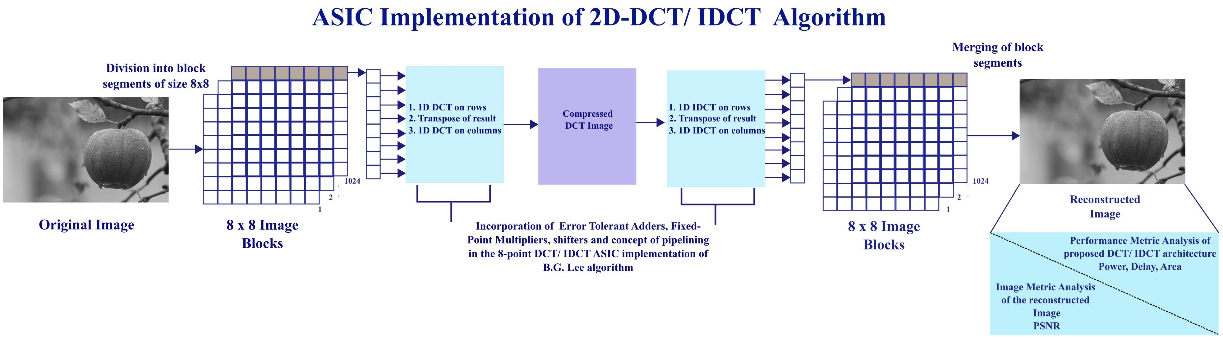
The digital image compression using the B.G. Lee algorithm was implemented on digital images of 256 × 256 pixels with a resolution of 8 bits. The structure of the 2D DCT/IDCT using the B.G. Lee algorithm with the proposed error-tolerant adders, the proposed fixed-point multiplier, and shifters is illustrated in Figure 5. The 256 × 256 digital image is divided into 1024 image segment blocks of size 8 × 8. Each 8 × 8 image segment block is then converted to [64:1] column matrices. Eight-point 1D DCT is performed on each [64:1] column matrix. This column matrix is once again converted to an 8 × 8 matrix, and then transposed and converted back to a [64:1] column matrix. Once again, eight-point 1D DCT is performed on this transposed column matrix. Now the compressed image is obtained.
The reverse process is applied to recover the digital image from the compressed form. Eight-point 1D IDCT is performed on each [64:1] column matrix. The column matrix is rearranged to form 8 × 8 image segments, the transpose of each image segment is taken, and then each 8 × 8 image segment is converted to a [64:1] column matrix. Finally, eight-point 1D IDCT is applied on this transposed matrix. The resultant column matrix is converted to the original 8 × 8 image block. The original image is recovered by merging all of the 8 × 8 image blocks.

3.1. Transposition Buffer Register for 2D DCT

The decomposition row–column technique is used for the DCT computation of each 8 × 8 image segment using the separability property of 2D DCT. The 2D DCT of an 8 × 8 image matrix is carried out with eight 8 × 1 1D DCTs. Figure 6 depicts the synchronization of a single pixel on an 8 × 8 block of an image using a clock signal. The 1D DCT is performed initially on the image block’s first row, represented by addresses R11 to R18. Then, the 1D DCT is carried out on the second row till it traverses to the eighth row. The 1D DCT is performed similarly for all 8 × 8 image blocks of the 256 × 256 image.
The data are input in a parallel manner in the proposed method. The transpose of each image block is as depicted in Figure 6 and each pixel element is 8 bits in size, represented by Rij, where the row is denoted by i and the column by j. In the first eight clock cycles, each row is written in parallel to the corresponding memory location such that each row becomes the column in the memory. To realize the transpose of each 8 × 8 image block, in the ninth clock, the pixels in M0 to M7 are read out simultaneously. The columns 1 to 8 of each 8 × 8 image block are read out in parallel in the clock cycles from 10 to 17. Once the 1D DCT is performed on all 8 × 8 image blocks, the transpose of each image block is taken to obtain the matrix, as indicated in Figure 6. The 1D DCT is applied on each 8 × 8 image block of the resultant matrix similarly. The image matrix obtained after 1D DCT operation is further processed to execute the 1D IDCT on each of the 8 × 8 image segments. The transpose of the resultant image matrix is obtained and the 1D IDCT is applied on the resultant 8 × 8 image blocks.

3.2. Architectural Design for B.G. LEE DCT Algorithm

The concepts of pipelining and approximate computing are applied to enhance the data of B.G. Lee’s eight-point algorithm for DCT and IDCT computations. The operations involved in each cycle are further simplified, and the performance is improved by using shift and add operations to reduce the multiplications.
The eight-point DCT design utilizing the B.G. Lee algorithm in conjunction with pipelining is shown in Figure 7. A pipelined method of eight stages is employed, where only a single mathematical computation is performed in each stage. Four adders and four subtractors are utilized to add and subtract the inputs x0–x7 in the first stage. The signed error-tolerant adders proposed in our work in [23] execute the arithmetic operations. The results of the first stage are stored in registers. The decimal values of the cosine coefficients are converted to their hexadecimal equivalents, which are stored as constants. In the second stage, these cosine constants are used in the multiplication process using the proposed fixed-point signed multiplier. The remaining multiplications of the second stage are accomplished utilizing shift and additions. Registers are utilized to store the results.
The third stage results are obtained using four addition and four subtraction operations. In the fourth stage, fixed-point signed multipliers are used to multiply the cosine constants with the subtractor results of the third stage. Alternate addition and subtraction operations are carried out in the fifth stage. The subtractor results obtained in the fifth stage are multiplied with cosine constants in the sixth stage. Four adders are used to carry out the addition operations in the seventh stage. Finally, in the eighth stage, the final DCT output is obtained by shifting the results of the seventh stage by one bit to the right to accomplish division by 2. The cosine constant factors used in Figure 7 are given in Table 1.
The multiplication operation is carried out using the proposed signed 16-bit fixed-point multipliers that are designed using shift and add operations. The most significant 8 bits represent the integer part, and the fraction part is represented by the least significant 8 bits of the multiplier and the multiplicand.
Figure 8 illustrates the design of the eight-point IDCT using the B.G. Lee algorithm in conjunction with pipelining. The coefficients obtained after DCT y0 to y7 are used as input to the IDCT structure. The different stages transition from 1 to 8 as the reverse operation of DCT. The input data x0 to x7 applied to the DCT are obtained as output after IDCT.
The input registers x0 to x7 in Figure 7 reflect the eight-point input pixel data. Clocks from 1 to 8 indicate the eight stages of the pipelined DCT/IDCT design. Eight clock cycles are needed to compute the 1D DCT/IDCT for an 8 × 8 image segment. The B.G. Lee algorithm’s DCT transformation involves four clock cycles for each row of pixels, making it idle for the next four clock cycles before taking the next pixel row. The redistribution of the input data and the incorporation of pipelining to uniformly distribute the arithmetic operations over the various stages is achieved in the proposed method. The DCT/IDCT operation is carried out for eight clock cycles by the inclusion of registers in such a way that only one addition or multiplication operation is included in each clock cycle. Table 2 and Table 3 depict the input data flow of the B.G. Lee eight-point DCT/IDCT algorithm.
The pipelined architecture that performs 2D DCT using the separability property by performing 1D DCT on the rows of each 8 × 8 image segment and on the columns is illustrated in Figure 9. The hardware architecture designed to perform 1D IDCT on the rows and columns of each 8 × 8 image segment is the same and has been reused. A 256 × 256 image is divided into smaller blocks of size 8 × 8. Each 8 × 8 image block comprises 64 pixels, containing eight rows and eight columns. All of the pixels are stored in the generated memory.
Each row of image pixels of the first 8 × 8 block is given as input to compute the 1D DCT and then each row is output per cycle after the transformation. Eight clock cycles are needed to compute the 1D DCT of the eight rows of each 8 × 8 image block. The bit widths of the digital input and output data of the eight-point DCT and IDCT with respect to the eight-stage pipeline architecture of Figure 7 and Figure 8 are tabulated in Table 4. The data range of the input image is −255 to 255 and the bit width is 9 bits for the first 1D DCT, where the sign bit is represented by the 9th bit. The width of the output obtained from the first 1D DCT is 17 bits. After eight clock cycles, the transpose of the transformed coefficients is taken. The transpose of the transformed coefficients is obtained in the 9th clock cycle. The columns of the transposed image is then subjected to 1D DCT. The input and output bit width of the data for the second 1D DCT is 17 bits. The computation of the 1D DCT on the resultant 8 × 8 image block requires 8 clock cycles. Once the 1D DCT is carried out, the 8 × 8 image blocks are ready for the IDCT transformation to recover the original image. The input and output bit width for the first 1D IDCT is 17 bits. In the next 8 clock cycles, the 1D IDCT is performed on the rows of the transformed image segment. The transpose of the resultant matrix is taken in the 9th clock cycle. Eight clocks are required to perform 1D IDCT on the columns of the resultant image segment to obtain the reconstructed image. The input bit width of the final 1D IDCT is 17 bits and the output bit width is 9 bits. Each 8 × 8 image block takes 34 clock cycles for the DCT and IDCT computation. The DCT algorithm is made more efficient by the integration of pipelining.
The incorporation of error-tolerant adders in the butterfly diagram computations, the utilization of the proposed low-power fixed point multipliers and shifters for the multiplications involved, along with the application of pipelining with the efficient row–column architectural design makes the B.G Lee algorithm implementation efficient in terms of power and computational efficiency. The 2D DCT/IDCT of each 8 × 8 image segment can be quickly processed in 34 clock cycles with a substantially reduced level of circuit complexity.

4. Results and Discussion

The proposed design is evaluated and assessed in terms of power, delay, and area using the hardware description language Verilog in this section. The image compression algorithm’s performance using the error-tolerant adder, proposed fixed-point multiplier, and the concept of pipelining was also assessed by analyzing the quality of the processed image.

4.1. Implementation of the Proposed Method

In order to evaluate the proposed design, the hardware description language Verilog was adopted to program the 2D DCT–IDCT image compression architecture. The image compression algorithm processes a 256 × 256 image with an 8-bit greyscale resolution. Figure 5 depicts the step-by-step procedure demonstrating the image compression technique and the underlying architectural model. The 256 × 256 digital input image is segregated into about 1024 8 × 8 image segments.
Two-dimensional DCT is performed on each 8 × 8 image block. This process involves applying 1D DCT to the rows, subsequently obtaining the transpose of the resultant image matrix and then performing 1D DCT to the resultant image matrix’s columns. The cosine terms involved are stored as constants, as all of the 8 × 8 image segments use the same values. The proposed error-tolerant adders are used to accomplish the additions and subtractions involved in the butterfly diagram. The multiplications are carried out using the proposed fixed-point multipliers and shifters.
The next step that must be applied is the reverse procedure required to recover the original image. One-dimensional IDCT is applied to the rows of the compressed image. Then, the transpose of the resultant matrix is taken, after which 1D IDCT is performed on the columns of the resultant matrix. The reconstructed image is recovered by merging all the 8 × 8 image segments.
The computational complexity of the proposed architecture and existing architectures is listed in Table 5. The addition, multiplication, and shift operation counts are shown for the reference and proposed algorithms. The proposed 2D DCT–IDCT image compression architecture and a few existing architectures were synthesized with gpdk-45 and 90 nm technology libraries for the ASIC implementation. The Genus tool of Cadence was used to generate the power, delay, area, and power delay product (PDP) of the 2D DCT–IDCT image compression architectures, as given in Table 6 and Table 7. A reduction of 31.01% in power, 12.17% in area, and 21.11% in PDP was observed with respect to the architecture in [25] when the synthesis was conducted using gpdk-90 nm technology libraries. When the synthesis was performed using gpdk-45 nm technology libraries, there was a reduction in power, area, and PDP of 28.21%, 5.95%, and 19.62%, respectively, with respect to the architecture in [25].

4.2. Image Metric Comparison of the Proposed DCT/IDCT Architectures

The simulation used four test images, Cameraman, Apple, Bird, and Lena, to evaluate the proposed DCT algorithm’s performance. The size of each image was 256 × 256, with unsigned 8 bits denoting each pixel. The block size of each image segment was 8 × 8, resulting in a total of 1024 blocks for evaluating the input image.
The Peak Signal-to-Noise Ratio (PSNR) [28] is used as the evaluation metric to assess the algorithm’s performance on the processed image quality. The computation of the Mean Square Error (MSE) is the first step to calculating the PSNR and estimating the variation of the two image’s pixel values. The PSNR and MSE are calculated according to Equations (7) and (8).
PSNR = 10   l o g 10 ( 2 n 1 ) 2 MSE  
MSE = 1 m n   x = 0 m 1 y = 0 n 1 [ I a ( x , y ) I e ( x , y ) ] 2
The PSNR of the images reconstructed using the B.G. Lee algorithm is represented in Table 8. In image processing applications involving digital images, the widely used figure of merit is PSNR. A higher PSNR is preferred as it indicates less distortion and noise in the image. PSNR values greater than 30 are usually preferred for image processing applications. The proposed architecture’s accuracy was verified by comparing the reconstructed image quality with other hardware architectures [9,25,26]. The comparison results of the PSNR of different methods are listed in Table 8. The reconstructed images using the proposed implementation are illustrated in Figure 10, where a, c, e, and g represent the input images, and the reconstructed images are denoted by b, d, f, and h. The PSNR of the proposed design was higher by 14.61%, 5.85%, and 4.55% than the PSNR of the architectures listed in [9,25,26].
The Innovus tool of Cadence was used to perform place and route. Figure 11 depicts the physical layout of the proposed design that was used for the image compression. The layout comprises a single polysilicon layer (Poly1) and nine distinct metal layers (M1 to M9). Post routing, to account for constant Process–Voltage–Temperature (PVT) change, power and static timing analysis was performed. The total negative slack (TNS) obtained from the analysis was zero.

5. Conclusions

The design and architecture of an efficient implementation for the 2D DCT/IDCT computation using the B.G. Lee algorithm was proposed in this research article. Incorporating the concept of pipelining, error-tolerant adders, fixed-point multipliers, shifters, and the row–column decomposition technique improved the computational efficiency and reduced the circuit complexity. The synthesis was performed with gpdk-45 nm and gpdk-90 nm standard semi-custom ASIC design flow using the Genus tool of Cadence. The synthesis results performed using 90 nm technology libraries indicated that the proposed implementation outperforms the existing architecture in [25] in terms of power, area, and PDP by 31.01%, 12.17%, and 21.11%, respectively. In comparison to the design in [25], there was a reduction in power, area, and PDP of 28.21%, 5.95%, and 19.62% when the synthesis was carried out using gpdk-45 nm technology libraries. The PSNR of the proposed design was better than the PSNR of the architectures specified in [9,25,26] by 14.61%, 5.85%, and 4.55%, respectively. A significant reduction in power, delay, and an improved PSNR was observed in the synthesis results. Future work will involve replacing the standard libraries with the optimized digital libraries from TSMC and realizing the design up to chip fabrication. The design can be extended further to make it suitable for high real-time performance required for video compression coding.

Author Contributions

Conceptualization, T.M. and S.G.N.; methodology, T.M.; software, T.M.; validation, T.M., S.G.N. and V.K.K.; formal analysis, T.M.; investigation, T.M. and S.G.N.; resources, T.M. and S.G.N.; writing—original draft preparation, T.M.; writing—review and editing, V.K.K., D.N. and H.S.M.; visualization, T.M.; supervision, S.G.N. All authors have read and agreed to the published version of the manuscript.

Funding

This research received no external funding.

Institutional Review Board Statement

Not applicable.

Informed Consent Statement

Not applicable.

Data Availability Statement

Not applicable.

Acknowledgments

The authors express their appreciation to Manipal Academy of Higher Education for offering them the TMA Pai scholarship necessary to complete this research. The authors would also like to express their gratitude to the Department of Electronics and Communication Engineering at Manipal Institute of Technology for providing the necessary laboratory environment and resources. The authors also thank Vikas R Bhat, MAHE, Manipal, for his valuable support.

Conflicts of Interest

The authors declare no conflict of interest.

References

  1. Chen, W.H.; Smith, C.H.; Fralick, S. A fast computational algorithm for the discrete cosine transform. IEEE Trans. Comm. 1977, 25, 1004–1009. [Google Scholar]
  2. Ahmed, N.; Natarajan, T.; Rao, K.R. Discrete cosine transform. IEEE Trans. Comp. 1984, 100, 90–93. [Google Scholar]
  3. Vetterli, M.; Nussbaumer, H.J. Simple FFT and DCT algorithms with reduced number of operations. Signal Proc. 1984, 6, 267–278. [Google Scholar]
  4. Hou, H. A fast recursive algorithm for computing the discrete cosine transform. IEEE Trans. Acoust. Speech Signal Proc. 1987, 35, 1455–1461. [Google Scholar]
  5. Cho, N.I.; Lee, S.U. Fast algorithm and implementation of 2-D discrete cosine transform. IEEE Trans. Circuits Syst. 1991, 38, 297–305. [Google Scholar]
  6. Loeffler, C.; Ligtenberg, A.; Moschytz, G.S. Practical fast 1-D DCT algorithms with 11 multiplications. In Proceedings of the IEEE International Conference on Acoustics, Speech, and Signal Processing, Glasgow, UK, 23–26 May 1989; pp. 988–991. [Google Scholar]
  7. El Aakif, M.; Belkouch, S.; Chabini, N.; Hassani, M. Low power and fast DCT architecture using multiplier-less method. In Proceedings of the IEEE Faible Tension Faible Consommation (FTFC), Marrakech, Morocco, 30 May–1 June 2011; pp. 63–66. [Google Scholar]
  8. Cintra, D.; Onen, V.; Dimitrov, N.; Madanayake, R.; Rajapaksha, L. A row-parallel 8 × 8 2-D DCT architecture using algebraic integer-based exact computation. IEEE Trans. Circuits Syst. Video Technol. 2011, 22, 915–929. [Google Scholar]
  9. Shen, Y.; Oh, H. Pipelined implementation of AI-based Loeffler DCT. IEICE Electron. Express 2013, 10, 20130319. [Google Scholar]
  10. Kitsos, P.; Voros, N.S.; Dagiuklas, T.; Skodras, A.N. A high speed FPGA implementation of the 2D DCT for ultra-high definition video coding. In Proceedings of the IEEE 18th International Conference on Digital Signal Processing (DSP), Fira, Greece, 1–3 July 2013; pp. 1–5. [Google Scholar]
  11. Edirisuriya, A.; Madanayake, A.; Cintra, R.J.; Dimitrov, V.S.; Rajapaksha, N. A Single-Channel Architecture for Algebraic Integer-Based 8×8 2-D DCT Computation. IEEE Trans. Circuits Syst. Video Technol. 2013, 23, 2083–2089. [Google Scholar]
  12. Coelho, D.F.; Nimmalapalli, S.; Dimitrov, V.S.; Madanayake, A.; Cintra, R.J.; Tisserand, A. Computation of 2D 8 × 8 DCT based on the Loeffler factorization using algebraic integer encoding. IEEE Trans. Comp. 2018, 67, 1692–1702. [Google Scholar]
  13. Xing, Y.; Zhang, Z.; Qian, Y.; Li, Q.; He, Y. An energy-efficient approximate DCT for wireless capsule endoscopy application. In Proceedings of the IEEE International Symposium on Circuits and Systems (ISCAS), Florence, Italy, 4 May 2018; pp. 1–4. [Google Scholar]
  14. Potluri, U.S.; Madanayake, A.; Cintra, R.J.; Bayer, F.M.; Kulasekera, S.; Edirisuriya, A. Improved 8-point approximate DCT for image and video compression requiring only 14 additions. IEEE Trans. Circuits Syst. I Regular Papers 2014, 61, 1727–1740. [Google Scholar]
  15. Kumar, U.A.; Jain, N.; Chatterjee, S.K.; Ahmed, S.E. Evaluation of Multiplier-Less DCT Transform Using In-Exact Computing. In Proceedings of the Second International Conference on Machine Learning, Image Processing, Network Security and Data Sciences, Silchar, India, 30–31 July 2020; Springer: Singapore, 2020; pp. 11–23. [Google Scholar]
  16. Balasubramanian, P.; Nayar, R.; Maskell, D.L. Digital Image Compression Using Approximate Addition. Electronics 2022, 11, 1361. [Google Scholar]
  17. Almurib, H.A.; Kumar, T.N.; Lombardi, F. Approximate DCT image compression using inexact computing. IEEE Trans. Comp. 2017, 67, 149–159. [Google Scholar] [CrossRef]
  18. Zhang, J.; Chow, P.; Liu, H. FPGA implementation of low-power and high-PSNR DCT/IDCT architecture based on adaptive recoding CORDIC. In Proceedings of the IEEE International Conference on Field Programmable Technology (FPT), Queenstown, New Zealand, 7–9 December 2015; pp. 128–135. [Google Scholar]
  19. Huang, J.; Kumar, T.N.; Almurib, H.A.; Lombardi, F. A deterministic low-complexity approximate (multiplier-less) technique for DCT computation. IEEE Trans. Circuits Syst. I Regular Papers 2019, 66, 3001–3014. [Google Scholar]
  20. Wu, Z.; Sha, J.; Wang, Z.; Li, L.; Gao, M. An improved scaled DCT architecture. IEEE Trans. Consum. Electron. 2009, 55, 685–689. [Google Scholar] [CrossRef]
  21. Shams, A.M.; Chidanandan, A.; Pan, W.; Bayoumi, M.A. NEDA: A low-power high-performance DCT architecture. IEEE Trans. Signal Proc. 2006, 54, 955–964. [Google Scholar]
  22. Lee, B. A new algorithm to compute the discrete cosine transform. IEEE Trans. Acoust. Speech Signal Proc. 1984, 32, 1243–1245. [Google Scholar]
  23. Mendez, T.; Nayak, S.G.; Kumar, P.V.; Kedlaya, K.V. Performance Metric Evaluation of Error-Tolerant Adders for 2D Image Blending. Electronics 2022, 11, 2461. [Google Scholar]
  24. Ochoa-Dominguez, H.; Rao, K.R. Discrete Cosine Transform, 2nd ed.; CRC Press: Boca Raton, FL, USA, 2019. [Google Scholar]
  25. Zhou, Z.; Pan, Z. Effective hardware accelerator for 2d DCT/IDCT using improved Loeffler architecture. IEEE Access 2022, 10, 11011–11020. [Google Scholar]
  26. Chen, M.; Zhang, Y.; Lu, C. Efficient architecture of variable size HEVC 2D-DCT for FPGA platforms. AEU-Int. J. Electron. Commun. 2017, 73, 1–8. [Google Scholar]
  27. Coelho, D.F.; Cintra, R.J.; Kulasekera, S.; Madanayake, A.; Dimitrov, V.S. Error-free computation of 8-point discrete cosine transform based on the Loeffler factorisation and algebraic integers. IET Signal Proc. 2016, 10, 633–640. [Google Scholar]
  28. Gonzalez, R.C.; Woods, R.E.; Masters, B.R. Digital Image Processing; Pearson International Edition: Bellingham, WA, USA, 2009. [Google Scholar]
  29. Mert, A.C.; Kalali, E.; Hamzaoglu, I. High performance 2D transform hardware for future video coding. IEEE Trans. Consum. Electron. 2017, 63, 117–125. [Google Scholar]
Figure 1. Data flowgraph structure of eight-point DCT using B.G Lee algorithm.
Applsci 13 09094 g001
Figure 2. Data flowgraph structure of eight-point IDCT using B.G Lee algorithm.
Applsci 13 09094 g002
Figure 3. Signed Error-Tolerant Adder for DCT/IDCT arithmetic operations.
Applsci 13 09094 g003
Figure 4. Proposed Signed Fixed-Point Multiplier.
Applsci 13 09094 g004
Figure 5. Block structure of the image compression process.
Applsci 13 09094 g005
Figure 6. Transpose implementation for each 8 × 8 image segment.
Applsci 13 09094 g006
Figure 7. Incorporation of error-tolerant adder and fixed-point multipliers in eight-point DCT using B.G. Lee algorithm.
Applsci 13 09094 g007
Figure 8. Incorporation of error-tolerant adder and fixed-point multipliers in eight-point IDCT using B.G. Lee algorithm.
Applsci 13 09094 g008
Figure 9. Pipelined architecture of 8 × 8 DCT–IDCT.
Applsci 13 09094 g009
Figure 10. Original and reconstructed images along with PSNRs using the proposed method. (a,c,e,g) Original Image. (b,d,f,h) Reconstructed images of (a,c,e,g) respectively using the proposed method.
Applsci 13 09094 g010
Figure 11. Layout of the proposed design.
Applsci 13 09094 g011
Table 1. DCT/IDCT cosine constant factors.
abcdefgh
1 2 c o s π 16 1 2 c o s 3 π 16 1 2 c o s 7 π 16 1 2 c o s 5 π 16 1 2 c o s 5 π 16 1 2 c o s 3 π 8 1 2 c o s π 4 1 8
Table 2. DCT data stream for eight-point B.G. Lee algorithm implementation.
I/PClockO/P
12345678
00 + 7 S20 + S22 S40 + S41 S60(S70).hX0
11 + 6 S21 + S23 S40–S41(S51).gS61S71 >> 1X4
23 + 4 S20–S22(S32).eS42 + S43 S62 + S63S72 >> 1X2
32 + 5 S21–S23(S32).fS42–S43(S53).gS63S73 >> 1X6
40–7(S14).aS24 + S26 S44 + S45 S64 + S66 + S67S74 >> 1X1
51–6(S15).bS25 + S27 S44–S45(S55).gS65 + S67S75 >> 1X5
63–4(S16).cS24–S26(S36).eS46 + S47 S65 + S66 + S67S76 >> 1X3
72–5(S17).dS25–S27(S37).fS46–S47(S57).gS67S77 >> 1X7
Table 3. IDCT data stream for eight-point B.G. Lee algorithm implementation.
I/PClockO/P
12345678
X0 I10 I30 + I31 I50 + I52 I70 + I74x0
X4 I11(I21).gI30–I31 I51 + I53 I71 + I75x1
X2 I12 I32 + I33(I42).eI50–I52 I72 + I76x3
X62 + 6I13(I23).gI32–I33(I43).fI51–I53 I73 + I77x2
X1 I14 I34 + I35 I54 + I56(I64).aI70–I74x7
X53 + 5I15(I25).gI34–I35 I55 + I57(I65).bI71–I75x6
X31 + 3I16 I36 + I37(I46).eI54–I56(I66).cI72–I76x4
X75 + 7I16 + I17(I27).gI36–I37(I47).fI55–I57(I67).dI73–I77x5
Table 4. DCT/IDCT data bit widths.
1D DCT/IDCTInput Bit WidthOutput Bit Width
1D DCT (Row)9 bits17 bits
1D DCT (Column)17 bits17 bits
1D IDCT (Row)17 bits17 bits
1D IDCT (Column)17 bits9 bits
Table 5. Proposed and existing DCT algorithms’ computational complexity.
Operations CountB.G Lee [22]Shen’s Method [9]FGA [7]Imp. Loeffler [25]Proposed
Adder2925675130
Multiplier120008
Shifter0N/A453413
Table 6. Analysis of power, delay, and area for different DCT/IDCT structures using 90 nm.
Technology: 90 nm
ArchitecturePower (mW)Delay (nS)Area (mm2)PDP (pJ)
Loeffler [6]27.8926.2845.53732.949
Shen’s Method [9]14.3224.0521.83344.396
B.G Lee [22]28.7631.2839.86899.612
HEVC [26]12.1527.6337.57335.704
CSD Met [27]12.2122.920.40287.301
EF Method [27]12.3123.5321.05289.654
Imp. Loeffler [25]15.1918.9737.63288.154
Proposed10.4821.6933.05227.311
Table 7. Analysis of power, delay and area for different DCT/IDCT structures using 45 nm.
Technology: 45nm
ArchitecturePower (mW)Delay (nS)Area (mm2)PDP (pJ)
Loeffler [6]25.9731.8122.76826.105
Shen’s Method [9]13.5128.3211.73382.603
B.G Lee [22]27.1835.2220.63957.279
HEVC [26]11.9632.8623.78393.005
CSD Met [27]11.7826.5110.20312.287
EF Method [27]11.4828.6511.04328.902
Imp. Loeffler [25]13.5423.6518.81320.221
Proposed9.7226.4817.69257.38
Table 8. PSNR comparison.
ImagePSNR (dB)
Shen’s Method [9]HEVC [26]High Per [29]Imp. Loeffler [25]Proposed
Cameraman33.78537.89333.9838.12440.476
Apple32.65434.91233.4635.48538.394
Bird36.29739.09837.2339.76840.511
Lena36.78439.16436.8939.56740.523
Average34.8837.76635.3938.23639.976
Disclaimer/Publisher’s Note: The statements, opinions and data contained in all publications are solely those of the individual author(s) and contributor(s) and not of MDPI and/or the editor(s). MDPI and/or the editor(s) disclaim responsibility for any injury to people or property resulting from any ideas, methods, instructions or products referred to in the content.

