1. Introduction
Intraoperative radiotherapy (IORT) is performed immediately after surgical removal of the tumor, providing direct irradiation of the tumor bed while minimizing radiation exposure to normal tissues and delivering a high dose to the tumor/tumor bed [
1]. Compared to external radiation therapy (EBRT), IORT offers several advantages, including a shorter interval between surgery and radiotherapy, preventing the repopulation of tumor cells, increased treatment dose due to the positional relationship between the tumor/tumor bed and adjacent normal tissue, and reduced treatment period with local irradiation where necessary [
2,
3,
4].
Moreover, numerous retrospective and randomized trial studies have demonstrated that IORT can be a viable alternative to EBRT. For instance, studies investigating the local recurrence rate and long-term survival rate of breast cancer patients who received IORT and EBRT found that IORT rates were non-inferior to EBRT rates [
5,
6,
7,
8]. In cases where EBRT was difficult to implement, such as sacral chordoma, locally advanced rectal cancer, pancreatic cancer, cervical cancer, and head and neck cancer with a high local recurrence rate, IORT may be a useful option [
9,
10,
11,
12,
13,
14,
15].
IORTs use either high-voltage electrons or low-kV X-ray systems [
16,
17,
18,
19]. The INTRABEAM system (Carl Zeiss Surgical, Oberkochen, Germany) is an IORT device that emits low X-ray energy of 20–50 kV. The main purpose of the applicator in IORT is to block the beam from spreading in all directions and to ensure that it is only incident in the target direction while stably positioning the X-ray generator on the tumor. The beam is focused on the target as much as possible to minimize the dosing incident on the surrounding normal tissue and enable stable treatment. The manufacturer of INTRABEAM offers four types of dedicated applicators: spheres, surfaces, planes, and needles. The spherical applicator shows an isotropic dose distribution and is used to deliver a uniform dose to the inner surface of the breast lumpectomy cavity. The surface and flat applicators exhibit a flat dose distribution due to a flattening filter and are used on the surface of the tumor bed. The needle applicator is designed for the treatment of vertebral metastases and brain tumors [
3].
Although the clinical application range of IORT has been expanded by providing various sizes and types of applicators, two fundamental problems remain. First, the isotropy of the spherical applicator allows high doses to enter a local area. Second, the current applicator is designed in a way that the X-ray generator and affected part meet vertically. However, in many cases, the angle between the tumor and X-ray generator may not be vertical, and it may be difficult to optimize the positioning of the X-ray generator using the current applicator.
Therefore, to protect normal tissues from the spherical applicator facing the tumor/tumor bed, radiation shielding should be provided for the areas around the target window. The situation where the tumor and X-ray generator are not perpendicular should be considered, and an applicator capable of irradiating the beam at an oblique angle other than 0° must be used.
In this study, an applicator dedicated to oblique beams was manufactured using 3D printing, and basic dose evaluations such as leakage dose, dose rate, and percent depth dose were performed. Finally, we used the developed applicator to treat four patients in a clinical setting.
2. Materials and Methods
2.1. INTRABEAM System
In this study, we utilized the INTRABEAM system (Carl Zeiss Surgical GmbH, Oberkochen, Germany), which is a device used for intraoperative radiotherapy and delivers low-energy X-rays directly to the tumor bed during surgery. The system comprises a floor stand, an X-ray source (Probe: 3.2 mm diameter, length: 100 mm), and a system cart containing a control console. The accelerating voltage was set to 40 or 50 kV, and the beam current was set to 40 μA at 40 kV and 5, 10, 20, or 40 μA at 50 kV. All measurements were performed using an INTRABEAM system with a 50 kV voltage tube.
2.2. Development of Applicator
The characteristics of the applicator developed for the INTRABEAM system are (1) improved flatness of the beam to achieve uniform tumor dose, (2) reduced leakage dose to nearby normal organs through the use of shielding materials, and (3) the ability to irradiate at a 45° angle to target hard-to-reach tumors.
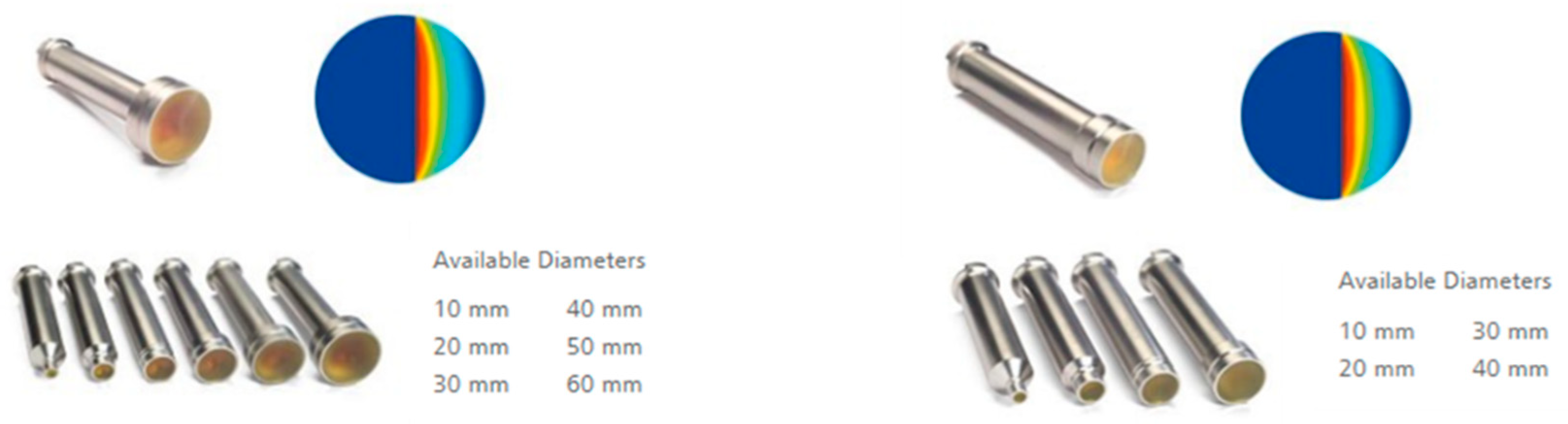
Figure 1 displays the flat and surface applicators provided by the manufacturer. The flat applicators offer a uniform dose distribution at a specific depth, while the surface applicators deliver a uniform dose distribution at the surface.
Figure 2a illustrates both a schematic and physical appearance of the add-on shielding device produced during this study. The framework of the add-on shield was created using 3D printing with PLA (polylactic acid) and is designed to enclose a spherical applicator. Cerrobend, a commercial alloy composed mainly of bismuth, lead, tin, and cadmium that has a low melting point, was inserted into this PLA framework to finalize the construction of the add-on shielding device. This alloy is often used in medical applications where customized shaping of shields is required. The thickness of the Cerrobend was determined to be 3 mm through a trial-and-error process. Moreover, by adjusting the thickness of PLA at the beam’s exit window, two filters of the add-on shielding device were developed: one for a flattened beam and another for an unflattened (FFF) beam. The device is intended to shield the surrounding area in the target direction with the inserted Cerrobend.
Figure 2b displays the types of add-on shielding devices designed, including (1) an unflattened beam at 0°, (2) a flattened beam at 0°, (3) an unflattened beam at 45°, and (4) a flattened beam at 45°.
2.3. Measurement and Evaluation
In this section, various measurements and evaluations were performed. The Gafchromic EBT3 film (Ashland, Wilmington, DE, USA), OSLD (optically stimulated luminescent dosimeters, Landauer, Wikiwand, IL, USA), and solid water phantom (RW3 slab phantom, PTW, Freiburg im Breisgau, Germany) were used to measure and evaluate the profile, percentage depth dose (PDD), leakage dose, and output of the beam [
20,
21]. The use of Gafchromic EBT3 film for dosimetry was particularly informed by the work of Sethi et al., which elaborates on the technical and dosimetric considerations for intraoperative radiotherapy with INTRABEAM [
3]. For scanning the irradiated EBT3 films, an EPSON Expression 11,000 XL scanner was utilized, which is capable of capturing images with a color depth of 16 bits per RGB channel, ensuring high precision in the recorded data. Uniformity was evaluated using the beam profile, and the PDD and output measurements were used for dose calibration. The irradiated EBT3 film was analyzed using the RIT (Radiological Imaging Technology, Colorado Springs, CO, USA) software v.6.11.
2.3.1. Leakage Dose and PDD
To assess the leakage dose and percent depth dose (PDD), we employed the EBT3 film and a human equivalent phantom, and we conducted vertical and horizontal measurements for all four applicators, in accordance with the methodology detailed by Schneider et al. [
22,
23]. The setup for the measurements can be seen in
Figure 3a,b, which were adapted from the guidelines provided in Schneider et al.’s study. The horizontal leakage dose was measured by positioning the developed applicator in the center of the EBT3 film, as depicted in
Figure 3c. We performed two irradiations for each measurement, with a radiation exposure of 96.7 cGy/min over a duration of 2 min for each irradiation.
2.3.2. Profile
We measured the beam profile of four developed applicators by placing EBT3 film between solid water at depths of 2, 5, and 15 mm (
Figure 4). We analyzed uniformity using RIT software by dividing the maximum dose (Dmax) by the minimum dose (Dmin) for each depth at 90% of the field size. The field size was defined as 50% of the central-axis dose of the profile. We compared our uniformity values with those obtained by Schneider et al. and with the size of the surface and flat applicators corresponding to the field size of the developed applicator.
2.3.3. Output Calibration
We verified the dose rate as 48.36 cGy/min for a 3 min period using OSLD absolute dose measurements (
Figure 5). Then, we obtained a dose calibration curve for EBT3 film analysis covering doses from 0 to 520 cGy, using the piecewise interpolation method.
To understand the differences in doses due to the presence or absence of a filter for the flattened beam and the FFF beam, the EBT3 film was irradiated at the same dose rate of 48.36 cGy/min for 3 min, and the outputs were compared.
3. Results
3.1. Leakage
Figure 6 shows the dose distributions for the four applicators. We did not evaluate the edges of the film placed on the surface of the applicator due to scanner artifacts. To evaluate the vertical and horizontal leakage, we excluded the cut side of the film as it is wrapped around the applicator. Instead, we considered a point of 0.5 mm from the surface of the applicator. We found no detectable dose beyond 0.5 mm from the surface of the four applicators.
3.2. Profile
Table 1 shows the uniformity calculated from the profiles of the 0° applicator with and without a flattening filter. We compared Schneider’s results for surface and flat applicator uniformity with our results for the surface and a depth of 5 mm.
3.3. The Output Calibration
The measured outputs for each applicator are shown in
Table 2. The difference between the 0° and 45° applicators with a flattening filter was 2.5 cGy, while the difference between the two models without a flattening filter was 1.9 cGy.
Figure 7 shows the calibration curve for the EBT3 film.
4. Discussion
The study’s novelty is the development of an inclined applicator for IORT that improved treatment performance and reduced unnecessary doses to normal tissues. The applicator directed the IORT beam at 45° and shielded it in other directions while forming a flattened beam for a uniform tumor dose delivery.
To ensure safe and effective beam delivery for IORT, quality assurance was necessary, and this study performed the leakage, beam profile, PDD, and output measurements to verify the dose distribution of each applicator prior to clinical use.
Figure 6 shows the shielding’s effectiveness, as the dose was not measured beyond 1 mm. Any dose appearing in the upper region of the horizontal leakage measurement can be explained with artifacts from bending or cutting the film surface during film cutting, as shown in
Figure 3c [
24].
The developed applicator showed an almost equal or better performance in terms of uniformity compared to flat and surface applicators measured by Schneider et al. [
22]. The developed IORT applicator demonstrated similar or superior performance to existing flat and surface applicators. To optimize treatment for the tumor bed, both the 0° and 45° applicators were designed to deliver a flat dose distribution at a depth of 5 mm, which is where the tumor bed exhibited the most uniform dose distribution. This was a significant improvement over the surface applicator, which was optimized for treatment but did not achieve the same level of uniformity [
25].
Our output measurements showed that applying the flat collimator or FFF collimator resulted in a slight difference in output for the 0° and 45° applicators. This is because the intensity of the X-ray decreases when the flattening filter is used. The small output difference between the 0° and 45° applicators allows for flexibility in adjusting the angle during the procedure and lowering the air gap between the applicator and the surrounding cavity. The difference in dose by approximately two times with and without the collimator can be explained by the decrease in dose due to the corresponding area, as the spherical applicator was shielded during development.
The developed applicator was clinically employed at Gangnam Severance Hospital on four patients after conducting dose evaluations (
Figure 8). Patient 1 presented a 2.86 cm lymph node metastasis on the posterior aspect of the left internal iliac vessel after undergoing low anterior resection for rectal adenocarcinoma (
Figure 8a). Patient 2 displayed a 1.9 cm metastasis at the left lateral edge of the mesorectal fascia following low anterior resection for rectal adenocarcinoma (
Figure 8b). Patient 3 presented with an approximately 1.6 cm mesenteric root metastasis after undergoing pylorus-preserving pancreaticoduodenectomy for adenocarcinoma in the ampulla of Vater (
Figure 8c). Patient 4 displayed a recurrence of invasive ductal carcinoma in the right breast after receiving definitive radiation therapy (
Figure 8d). The decision to employ IORT was made based on the evaluation of experienced surgical and radiation oncologists. After obtaining clinical consent from each patient to use the developed applicator, the surgical procedure was performed. It is important to note that the applicator itself is designed to be reusable and can be used for subsequent procedures. To account for the characteristic of PLA being deformed at high temperatures, a low-temperature sterilization method that involves heating at below 100 °C for several minutes was used for the shielding device. Additionally, in
Figure 8e–g, which depict the surgical scene, the applicator was enclosed in disposable polyethylene material that was discarded after surgery.
One limitation of this study was the size of the applicators used. The developed applicator used in this study was based on a spherical applicator provided by Carl Zeiss, which comes in various sizes ranging from 3 to 5 cm in diameter. However, a shielding device was added to cover the spherical applicator, and a thickness of 1 cm was added by adding 0.5 cm on each side. This may lead to soft tissue compression in the breast IORT protocol, and even if a 3 cm applicator was used, the thickness starts from 4 cm, which may be burdensome [
26,
27]. This thickness is typically used when there is sufficient space in the abdomen.
Second, there were also limitations in the tools used for basic dose inspection. The EBT3 film, while a common tool for evaluating dose distribution in radiation therapy, was difficult to use on the cutting surface. The solid water phantom, although useful for visualizing dose distribution, had limitations in verifying results before clinical application. Monte Carlo calculation methods are necessary for generating simulations, obtaining complete 3D dose distributions, and quantifying the effects of various parameters. Furthermore, artifacts from the scanner resolution could not be excluded in EBT3 film measurements.
5. Conclusions
This study developed an inclined applicator that delivers a uniform dose to the tumor/tumor bed and shields unnecessary areas. Basic dose evaluation was successfully performed, and clinical applications were performed. The developed applicator will facilitate treatment in the abdomen or chest, where critical organs are present, and expand the clinical application range of IORT.
Author Contributions
Conceptualization, J.H.K., K.P. and J.S.K.; Methodology, J.H.K. and S.A.; Software, J.H.K.; Validation, K.P. and R.L.; Formal analysis, S.A.; Investigation, J.H.K.; Data curation, K.P.; Writing—original draft, J.H.K.; Writing—review & editing, K.P.; Visualization, K.P.; Supervision, S.A.; Project administration, S.A. All authors have read and agreed to the published version of the manuscript.
Funding
This research was supported by the Basic Science Research Program through the National Research Foundation of Korea (NRF) funded by the Ministry of Education (grant number) (NRF-2022R1I1A1A0107158811), faculty research grant of Yonsei University College of Medicine (6-2022-0062), National Research Foundation of Korea (NRF) grant funded by the Korea government (MSIT) (No. 2022R1A2C2008623), National Research Foundation of Korea (NRF) grant funded by the Korean government (MISIT) (No. 2022R1H1A2092091), and Korea Institute of Energy Technology Evaluation and Planning (KETEP) grant funded by the Korean government (MOTIE) (20227410100050).
Institutional Review Board Statement
The studies involving human participants were reviewed and approved by The Institutional Review Board of the Gangnam Severance Hospital, Korea (IRB No. 3-2017-0033) in accordance with ethical guidelines and the Declaration of Helsinki. The patients/participants provided their written informed consent to participate in this study. Written informed consent was obtained from the individual(s) for the publication of any potentially identifiable images or data included in this article.
Informed Consent Statement
Not applicable.
Data Availability Statement
Not applicable.
Conflicts of Interest
The authors declare no conflict of interest.
References
- Hensley, F.W. Present state and issues in IORT Physics. Radiat. Oncol. 2017, 12, 37. [Google Scholar] [CrossRef] [PubMed] [Green Version]
- Pilar, A.; Gupta, M.; Ghosh Laskar, S.; Laskar, S. Intraoperative radiotherapy: Review of techniques and results. Ecancermedicalscience 2017, 11, 750. [Google Scholar] [CrossRef] [PubMed] [Green Version]
- Sethi, A.; Emami, B.; Small, W.; Thomas, T.O. Intraoperative Radiotherapy with INTRABEAM: Technical and Dosimetric Considerations. Front. Oncol. 2018, 8, 74. [Google Scholar] [CrossRef] [PubMed]
- Akhtari, M.; Teh, B.S. Accelerated partial breast irradiation: Advances and controversies. Chin. J. Cancer 2016, 35, 31. [Google Scholar] [CrossRef] [Green Version]
- Rana, S.; Naik, A.; Pillai, S.; Vetto, J.; Pommier, R.; Kubicky, C.D. Outcomes of intraoperative radiotherapy for early-stage breast cancer: Experience from a multidisciplinary breast oncology program. Am. J. Surg. 2020, 219, 655–659. [Google Scholar] [CrossRef]
- Vaidya, J.S.; Bulsara, M.; Baum, M.; Wenz, F.; Massarut, S.; Pigorsch, S.; Alvarado, M.; Douek, M.; Saunders, C.; Flyger, H.L.; et al. Long term survival and local control outcomes from single dose targeted intraoperative radiotherapy during lumpectomy (TARGIT-IORT) for early breast cancer: TARGIT-A randomised clinical trial. BMJ 2020, 370, m2836. [Google Scholar] [CrossRef]
- Hashemi, S.; Javadi, S.; Akbari, M.E.; Mirzaei, H.; Mahdavi, S.R. Comparison of IORT (Radical and Boost Dose) and EBRT in Terms of Disease-Free Survival and Overall Survival according to Demographic, Pathologic, and Biological Factors in Patients with Breast Cancer. Int. J. Surg. Oncol. 2021, 2021, 2476527. [Google Scholar] [CrossRef]
- Byun, H.K.; Kim, N.; Seong, J. Optimal Timing of Radiotherapy after Incomplete Transarterial Chemoembolization for Barcelona Clinic Liver Cancer Stage B Hepatocellular Carcinoma. Yonsei Med. J. 2021, 62, 409–416. [Google Scholar] [CrossRef]
- Jullien-Petrelli, A.C.; García-Sabrido, J.L.; Orue-Echebarria, M.I.; Lozano, P.; Álvarez, A.; Serrano, J.; Calvo, F.M.; Calvo-Haro, J.A.; Lasso, J.M.; Asencio, J.M. Role of intraoperative radiotherapy in the treatment of sacral chordoma. Spine J. 2018, 18, 632–638. [Google Scholar] [CrossRef]
- Potemin, S.; Kübler, J.; Uvarov, I.; Wenz, F.; Giordano, F. Intraoperative radiotherapy as an immediate adjuvant treatment of rectal cancer due to limited access to external-beam radiotherapy. Radiat. Oncol. 2020, 15, 11. [Google Scholar] [CrossRef]
- Barney, B.M.; Petersen, I.A.; Dowdy, S.C.; Bakkum-Gamez, J.N.; Klein, K.A.; Haddock, M.G. Intraoperative Electron Beam Radiotherapy (IOERT) in the management of locally advanced or recurrent cervical cancer. Radiat. Oncol. 2013, 8, 80. [Google Scholar] [CrossRef] [Green Version]
- Münter, M.W.; Köppen, U.; Ramuscak, A.; Sittel, C.; Wegn, N. Intraoperative radiotherapy (IORT) in the treatment of head and neck cancer. Transl. Cancer Res. 2015, 4, 178–181. [Google Scholar] [CrossRef]
- Chiodo, C.; Gros, S.; Lee, B.; Block, A.M.; Emami, B.; Small, W.; Abdelrhman, T.R. Intraoperative radiation therapy for locally advanced and recurrent head and neck cancer. J. Clin. Oncol. 2022, 40, 6058. [Google Scholar] [CrossRef]
- Cho, Y.; Kim, J.W.; Kim, H.S.; Park, J.S.; Lee, I.J. Intraoperative Radiotherapy for Resectable Pancreatic Cancer Using a Low-Energy X-ray Source: Postoperative Complications and Early Outcomes. Yonsei Med. J. 2022, 63, 405–412. [Google Scholar] [CrossRef]
- Roeder, F.; Goetz, J.-M.; Habl, G.; Bischof, M.; Krempien, R.; Buechler, M.W.; Hensley, F.W.; Huber, P.E.; Weitz, J.; Debus, J. Intraoperative Electron Radiation Therapy (IOERT) in the management of locally recurrent rectal cancer. BMC Cancer 2012, 12, 592. [Google Scholar] [CrossRef] [Green Version]
- Krempien, R.; Roeder, F. Intraoperative radiation therapy (IORT) in pancreatic cancer. Radiat. Oncol. 2017, 12, 8. [Google Scholar] [CrossRef] [Green Version]
- Kates, M.; Chappidi, M.R.; Brant, A.; Milbar, N.; Sopko, N.A.; Meyer, C.; Terezakis, S.A.; Herman, J.M.; Efron, J.E.; Safar, B.; et al. High dose-rate Intra-Operative Radiation Therapy During High Risk Genitourinary Surgery: Initial Observations and a Proposal for its Study in Bladder Cancer. Bladder Cancer 2017, 3, 191–199. [Google Scholar] [CrossRef]
- Tallet, A.; Racadot, S.; Boher, J.-M.; Cohen, M.; Barrou, J.; Houvenaeghel, G.; Gutowski, M.; Delmond, L.; Lemanski, C. The actual benefit of intraoperative radiation therapy using 50 kV x-rays in early breast cancer: A retrospective study of 676 patients. Breast J. 2020, 26, 2145–2150. [Google Scholar] [CrossRef]
- Kraus-Tiefenbacher, U.; Scheda, A.; Steil, V.; Hermann, B.; Kehrer, T.; Bauer, L.; Melchert, F.; Wenz, F. Intraoperative radiotherapy (IORT) for breast cancer using the Intrabeam system. Tumori 2005, 91, 339–345. [Google Scholar] [CrossRef]
- Papaconstadopoulos, P.; Hegyi, G.; Seuntjens, J.; Devic, S. A protocol for EBT3 radiochromic film dosimetry using reflection scanning. Med. Phys. 2014, 41, 122101. [Google Scholar] [CrossRef]
- Marroquin, E.Y.L.; Herrera González, J.A.; Camacho López, M.A.; Villarreal Barajas, J.E.; García-Garduño, O.A. Evaluation of the uncertainty in an EBT3 film dosimetry system utilizing net optical density. J. Appl. Clin. Med. Phys. 2016, 17, 466–481. [Google Scholar] [CrossRef] [PubMed]
- Schneider, F.; Clausen, S.; Thölking, J.; Wenz, F.; Abo-Madyan, Y. A novel approach for superficial intraoperative radiotherapy (IORT) using a 50 kV X-ray source: A technical and case report. J. Appl. Clin. Med. Phys. 2014, 15, 167–176. [Google Scholar] [CrossRef] [PubMed]
- Steenbeke, F.; Gevaert, T.; Tournel, K.; Engels, B.; Verellen, D.; Storme, G.; De Ridder, M. Quality Assurance of a 50-kV Radiotherapy Unit Using EBT3 GafChromic Film: A Feasibility Study. Technol. Cancer Res. Treat. 2016, 15, 163–170. [Google Scholar] [CrossRef] [PubMed] [Green Version]
- Costa, F.; Sarmento, S.; Sousa, O. Assessment of clinically relevant dose distributions in pelvic IOERT using Gafchromic EBT3 films. Phys. Med. 2015, 31, 692–701. [Google Scholar] [CrossRef] [Green Version]
- Lam, S.C.P.; Xu, Y.; Ingram, G.; Chong, L. Dosimetric characteristics of INTRABEAM® flat and surface applicators. Transl. Cancer Res. 2014, 3, 106–111. [Google Scholar] [CrossRef]
- Kaiser, J.; Reitsamer, R.; Kopp, P.; Gaisberger, C.; Kopp, M.; Fischer, T.; Zehentmayr, F.; Sedlmayer, F.; Fastner, G. Intraoperative Electron Radiotherapy (IOERT) in the Treatment of Primary Breast Cancer. Breast Care 2018, 13, 162–167. [Google Scholar] [CrossRef]
- Holmes, D.R. Intraoperative radiotherapy in breast conserving surgery: IORT in Breast Conserving Surgery. J. Surg. Oncol. 2014, 110, 68–74. [Google Scholar] [CrossRef]
Figure 1.
(Left) flat and (right) surface applicators.
Figure 1.
(Left) flat and (right) surface applicators.
Figure 2.
Design diagram and types of developed applicators: (a) The location and actual picture of each part of the add-on shielding device. The blue part represents 3D-printed PLA, within which Cerrobend (yellow) is inserted; (b) the conceptual design of the four types of developed applicators.
Figure 2.
Design diagram and types of developed applicators: (a) The location and actual picture of each part of the add-on shielding device. The blue part represents 3D-printed PLA, within which Cerrobend (yellow) is inserted; (b) the conceptual design of the four types of developed applicators.
Figure 3.
Experimental setup for measuring the vertical leakage dose and PDD for (a) 0° and (b) 45°, as well as that for measuring the (c) horizontal leakage dose for 0°.
Figure 3.
Experimental setup for measuring the vertical leakage dose and PDD for (a) 0° and (b) 45°, as well as that for measuring the (c) horizontal leakage dose for 0°.
Figure 4.
The experimental setup used to measure the beam profile of the developed applicators. The measurements were conducted on the surface and at depths of 2, 5, and 15 mm of the solid water phantom.
Figure 4.
The experimental setup used to measure the beam profile of the developed applicators. The measurements were conducted on the surface and at depths of 2, 5, and 15 mm of the solid water phantom.
Figure 5.
The output calibration of the dedicated applicator, OSLD, film. A tool capable of mounting both OSLD and EBT3 film was attached to the window of the shielding device.
Figure 5.
The output calibration of the dedicated applicator, OSLD, film. A tool capable of mounting both OSLD and EBT3 film was attached to the window of the shielding device.
Figure 6.
Measured horizontal and vertical leakage dose and PDD for a 0° applicator with and without a flattening filter: (a) horizontal leakage dose for 0° applicator; (b) vertical leakage dose for 0° applicator; (c) PDD for 0° applicator with a flattening filter; (d) PDD for 0° applicator without a flattening filter; (e) horizontal leakage dose for 45° applicator; (f) vertical leakage dose for 45° applicator; (g) PDD for 45° applicator with a flattening filter; and (h) PDD for 45° applicator without a flattening filter.
Figure 7.
Calibration curve of the developed applicator obtained from RIT software.
Figure 7.
Calibration curve of the developed applicator obtained from RIT software.
Figure 8.
Intraoperative treatment using the developed applicator: (a,b) axial magnetic resonance images for Patients 1 and 2, respectively; (c,d) PET/CT image of Patients 3 and 4, respectively; (e–g) applicator setup for Patients 2, 3, and 4, respectively; green arrows represent the location of tumors.
Table 1.
Measured uniformity of the developed applicators at surface and depths of 2, 5, and 15 mm.
Table 1.
Measured uniformity of the developed applicators at surface and depths of 2, 5, and 15 mm.
| | Uniformity |
|---|
| | Surface | 2 mm Depth | 5 mm Depth | 15 mm Depth |
|---|
| 0° FF | 1.23 | 1.28 | 1.30 | 1.22 |
| Flat appl. * | 1.31 | - | 1.13 | - |
| 0° FFF | 1.29 | 1.32 | 1.27 | 1.25 |
| Surface appl. * | 1.28 | - | 1.47 | - |
Table 2.
The output of the developed applicator.
Table 2.
The output of the developed applicator.
| | Type of Applicator |
|---|
| | 0° Flattening Filter | 45° Flattening Filter | 0° FFF | 45° FFF | w/o Filter |
|---|
| Dose (cGy) | 51.0 | 48.5 | 52.9 | 54.8 | 113.7 |
| Disclaimer/Publisher’s Note: The statements, opinions and data contained in all publications are solely those of the individual author(s) and contributor(s) and not of MDPI and/or the editor(s). MDPI and/or the editor(s) disclaim responsibility for any injury to people or property resulting from any ideas, methods, instructions or products referred to in the content. |
© 2023 by the authors. Licensee MDPI, Basel, Switzerland. This article is an open access article distributed under the terms and conditions of the Creative Commons Attribution (CC BY) license (https://creativecommons.org/licenses/by/4.0/).


