Article

Radial Gradient Seismic Metamaterials with Ultra-Low Frequency and Ultra-Wide Band Gap

School of Mechanical and Electrical Engineering, Xi’an University of Architecture and Technology, Xi’an 710055, China
*
Author to whom correspondence should be addressed.
Appl. Sci. 2023, 13(16), 9284; https://doi.org/10.3390/app13169284
Submission received: 13 July 2023 / Revised: 7 August 2023 / Accepted: 11 August 2023 / Published: 16 August 2023

Abstract

:
In this paper, a radial gradient seismic metamaterial (RGSM) is proposed. The structural unit cell is composed of an external square soil embedded with a triangular-cross-sectioned steel ring, which is filled at different angles of multiple steel rings to form a supercell. The dispersion curve and attenuation spectrum of the unit cell are calculated by the finite element method, and the opening mechanism of the band gap is explained by analyzing the modes at the band gap boundary. The influence of geometric parameters and material parameters on the band gap is further studied, and the optimized supercell radial gradient seismic metamaterial (OS-RGSM) structure is designed through structure and parameter optimization. The ultra-low broadband excellent band gap in the range of 2.35–20 Hz for seismic Lamb waves is realized, and its three-dimensional frequency response and displacement field diagram are calculated. In addition, the attenuation characteristics of the optimized supercell seismic metamaterial on the seismic surface wave are calculated and analyzed. It is found that the attenuation can reach more than 50% in the ultra-low frequency range of 3.5–9 Hz. The seismic wave barrier is verified by the vibration transmission characteristics of RGSM under finite period and dynamic time history analysis. The results show that RGSM can effectively shield from seismic Lamb waves in the ultra-wideband with the starting frequency of 2.35 Hz and can also effectively attenuate the seismic surface wave in semi-infinite space.

1. Introduction

Earthquakes are one of the most catastrophic natural disasters, and the spread of seismic sources causes significant damage to structures, further leading to consumption and damage to various aspects of social resources [1,2,3]. Seismic metamaterial, as an artificial structure that attenuates seismic waves, can generate a band gap corresponding to the seismic frequency, providing a new idea for building protection [4,5,6].
Seismic surface waves have the characteristics of large amplitude, long propagation distance, and low frequency, which cause great harm to buildings. For a long time, the research on seismic metamaterial has focused on surface waves [7,8]. Seismic Lamb waves are ignored as another form of seismic wave propagation. Research has found that in cases of near-surface earthquakes, the propagation of Lamb waves is particularly important for damage to buildings [9], usually dominating the seismic records of local and regional events [10]. Therefore, in the design of seismic metamaterial, not only the isolation design of surface waves but also the shielding characteristics of lamb waves should be studied [11,12].
Du et al. [13] studied the shielding effect of periodic concrete structures on seismic Lamb waves, determined the blocking effect of periodic structures on Lamb waves, and confirmed the existence of low-frequency band gaps. However, there is still a narrow range of shock absorption. Mesegue et al. [14] used triangular and honeycomb periodic arrays to drill holes on marble to form a metamaterial structure, which verified that this structure can generate band gaps and can be used to attenuate Lamb waves in seismic waves. Hong Kim et al. [15] developed a new seismic isolation method, proposed a method of applying metamaterials to the field of seismic isolation, and designed a hollow cylinder as an earthquake metamaterial wave barrier. The structure does not contact the protected building, which can effectively convert the energy of the earthquake’s Lamb waves into heat energy for dissipation. However, at present, the Lamb band gap of seismic metamaterials is still narrow, and the engineering application is limited. Radial metamaterials are widely used in various fields of vibration isolation and noise reduction because of their excellent band gap characteristics and omnidirectional shielding [16,17,18,19]. Li et al. [20] introduced radial metamaterials into seismic metamaterials, proposed radial seismic metamaterials, studied the propagation characteristics of seismic Lamb waves and surface waves, and obtained a wide band gap.
Gradient design is applied to metamaterial [21,22,23], showing diversified characteristics. Lin et al. [24] designed a two-dimensional gradient refractive index phononic crystal, indicating that gradient refractive structures can perform acoustic focusing over a wide operating frequency range. Ma et al. [25] designed a functional gradient material pipeline structure and found that functionally gradient materials can effectively regulate the bandgap characteristics of classical periodic structures. The biggest advantage of gradient arrangement is that it can manipulate the transmission of elastic waves over a wide frequency range [21,22]. Liu et al. [26] put forward that the arrangement is the seismic metamaterial with gradient burial depth. The transmission spectrum of its finite structure shows that it has better isolation effect on surface waves in a wider band gap. However, the dispersion curve of the graded seismic metamaterial structure has not been calculated and studied, and the mechanism of band gap widening has not been analyzed.
Supercells are composed of several cells with different parameters. The method of calculating the electronic band structure based on the periodic structure of supercells is called supercells method [27]. Zhao et al. [27] proposed a supercell phononic crystal plate composed of dual oscillator units and single oscillator units. The research results indicate that the frequency of this structure can be better applied to low-frequency regions. Yuan et al. [28] validated the characteristic of adjusting the bandgap of supercell structure by designing a supercell phononic crystal plate and obtained a wide and low-frequency bandgap. Young et al. [29] designed a 45° rotating supercell and achieved band gap optimization. In addition, the idea of realizing multi-resonant modes or achieving the best results by changing the parameters is also applied to the control of electromagnetic waves [30,31]. The supercell method provides a possibility for studying the mechanism of widening bandgap using periodic gradient arrangement.
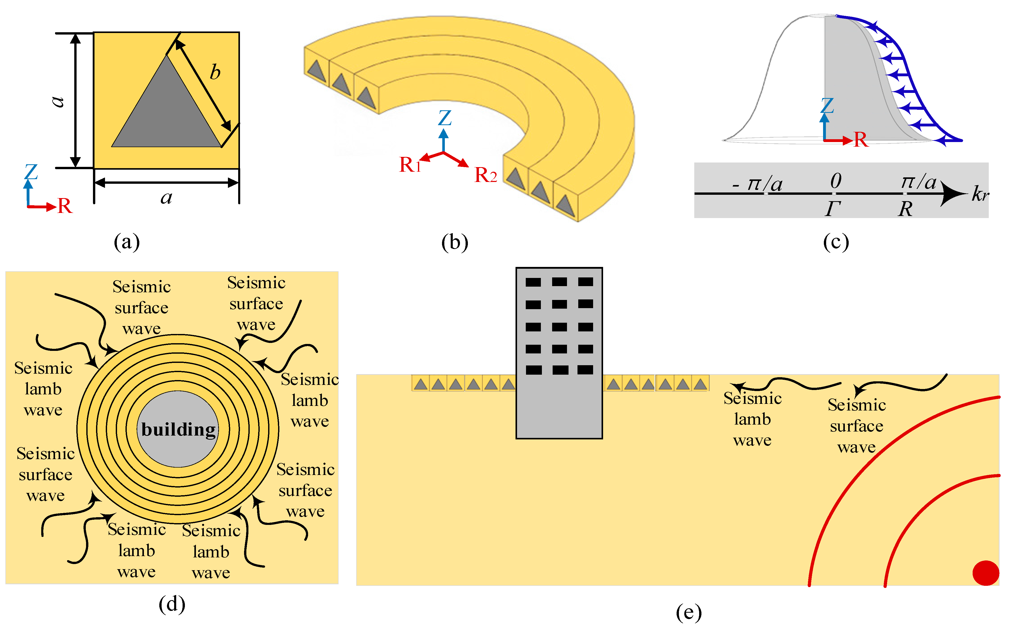
In this paper, the gradient idea is applied to the design of radial seismic metamaterial, and its low-frequency broadband characteristics and mechanism are analyzed and studied with supercell method. Firstly, the dispersion curve and attenuation spectrum of the radial gradient seismic metamaterial (RGSM) single-cell structure are calculated using finite element software, and the mode at the boundary of the band gap is analyzed. The influence of geometric parameters and material parameters on the band gap is further studied. The optimized supercell seismic metamaterial structure is designed through structure and parameter optimization, and its three-dimensional frequency response and displacement field diagram are calculated for analysis and verification. Finally, the attenuation effect of a radial gradient supercell seismic metamaterial on seismic surface waves is studied using a three-dimensional model and is verified in time domain.

2. Materials and Methods

The propagation of seismic waves can be described by the propagation of elastic waves in inhomogeneous media. Assuming that the seismic wave propagates along the radial mid-plane of the structure, the governing equations can be written as:
ρ r u .   . r = { [ λ r + 2 μ r ] ( · u r ) } × μ r × u r
where u(r) represents the displacement vector; ρ(r) denotes the mass density; λ(u), μ(r) are the Lamb wave constants of the material. Due to the particularity of the structure, Equation (1) is extended to cylindrical coordinates. At this time, the wave equation can be rewritten as:
ρ 2 u t 2 = λ + 2 μ θ t r 2 μ r w z θ + 2 μ w θ θ ρ 2 v t 2 = λ + 2 μ θ t r θ 2 μ w z θ + 2 μ w r r ρ 2 w t 2 = λ + 2 μ θ t z 2 μ r r r w θ + 2 μ r w r θ
where u, v, and w are the displacement components of the rectangular coordinate system; ρ is the density; t is the time; λ and μ are the elastic wave constants of the material; and r, θ, and z are the coordinates in the cylindrical coordinate system.
In addition, the volume strain θ t and the rotational component ( w r , w θ , w z ) in the cylindrical coordinate system are defined as follows:
θ t = 1 r r u r + 1 r v θ w z w r = 1 2 1 r w θ + 1 r v z w θ = 1 2 1 r u θ + w r w z = 1 2 1 r r v θ + u θ
According to Bloch’s theorem, the infinite periodic radial lattice unit can be simplified to a single lattice unit, and the boundary conditions of the lattice can be expressed as follows:
u r + r a , z = u r , z e i k r r a
where a is the lattice constant, r is the radial position vector, and Kr represents the Bloch radial wave vector. Here, the Floquet periodic boundary condition is applied to the boundary connection of the unit cell. The top and bottom surfaces of the unit cell are free boundary conditions, that is, there is no reflection component on the surface.

3. The Radial Gradient Seismic Metamaterial Structure

3.1. Unit Cell Model

The radial gradient seismic metamaterial (RGSM) structure designed in this paper is periodically arranged around the building to be protected along the radial direction, forming a seismic metamaterial barrier. The unit cell lattice structure is shown in Figure 1a; a represents the length of its unit lattice, b represents the length of the side length of the filler, and the three sides of the cross section of the filler are equal and located in the center of the square structure. Its three-dimensional structure is composed of a radial section rotating around the central axis as shown in Figure 1b; Figure 1c shows the formation of its three-dimensional structure more intuitively. The triangular cross-section radial metamaterial unit cell is composed of an external square soil frame nested with an internal triangular cross-section steel ring and placed on the soil surface. The surface is the same height as the surface of the surrounding soil layer, as shown in Figure 1d,e.
The yellow area in the figure is soil, and the gray area is steel. According to the survey data of different earthquakes, the corresponding wavelength of seismic waves varies from hundreds of meters to several meters. Therefore, the unit cell structure with a lattice constant of 4 m studied in this chapter is almost one 20th of the wavelength of seismic waves. The geometric parameters of the unit cell are lattice constant a = 4   m and triangle side length b = 3   m . In order to effectively control the project cost, the building materials used in this structure are soil and steel. The materials used are assumed to be linear elastic, homogeneous and isotropic. The material parameters of the barrier unit model are soil density ρ s = 1800   k g / m 3 ; Young’s modulus E s = 2 × 10 7   P a ; Poisson’s ratio υ s = 0.3 . The density of steel ρ c = 7784   k g / m 3 ; Yung’s modulus E c = 2.07 × 10 11   P a ; Poisson’s ratio υ c = 0.3 .

3.2. Band Gap and Mechanism Analysis

The finite element software COMSOL Multiphysics 5.5 was used to simulate the RGSM structure, and the calculation results are shown in the band structure of Figure 2a. It can be observed from the figure that there are three complete band gaps below 20 Hz, and the frequency ranges of the band gaps are 5.3484–13.882 Hz, 15.016–15.274 Hz, and 18.488–20 Hz, respectively. In order to further verify the shielding effect of triangular cross-section radial seismic metamaterials on Lamb waves, we calculated the incident wave frequency response curve of the nine-cycle radial periodic structure, as shown in Figure 2b. The attenuation domain in the frequency response curve is basically consistent with the band gap range in the energy band curve.
In order to explore the generation mechanism of the band gap, the vibration modes at several special points in the band structure diagram are calculated, as shown in Figure 3. It can be seen from the figure that the vibration mode of point A1 is mainly the axial vibration of the steel ring in the unit, and the soil acts as the matrix. The mode of A2 is mainly manifested as the vibration of the soil in the unit cell. The vibration of the upper soil is wavy from the outer soil to the inner soil, and the steel layer remains stationary at this time. The A3 mode is mainly manifested as bottom and inner vibration, and the steel layer is still relatively static. A4 and A3 have the same vibration mode. Compared to the vibration state under the A3 mode, the vibration intensity at the bottom of the unit cell under the A4 mode is weaker.

3.3. The Effect of Filling Angle on the Band Gap

For further research and analysis, the low-frequency broadband characteristics of Lamb waves generated by RGSM. Under the condition that other parameters remain unchanged, we analyze the influence of the filling angle on the band gap. The angle in Figure 4a is 0 degrees, and the band gap characteristics are analyzed from the special angles of 0 degrees, 45 degrees, 90 degrees, and 270 degrees. From Figure 4, it can be observed that the first band gap will change due to different filling angles. As shown in Figure 4a, the starting frequency and ending frequency of the first band gap are 5.3484 Hz and 13.882 Hz, respectively; the starting and ending frequencies of the first band gap shown in Figure 4b are 5.28561 Hz and 14.025 Hz, respectively. The starting frequency and ending frequency of the first band gap shown in Figure 4c are 5.4536 Hz and 14.19 Hz, respectively. The starting frequency and cutoff frequency of the first band gap shown in Figure 4d are 5.2493 Hz and 14.285 Hz, respectively. The vibration modes of the band gap terminal are consistent, which are the vibration of the steel ring and the vibration of the soil ring respectively.

3.4. The Effect of Filling Rate on Band Gap

In addition, under the premise of the same properties of the filling material, we studied the influence of the filling rate on the band gap. For the filled steel ring, the band calculation is carried out when the cross-sectional side length b2 is 2 m, 2.5 m, 3 m, and 3.5 m, as shown in Figure 5a. For the unit cell with a cross-sectional side length b2 = 2 m, the initial frequency and cutoff frequency of the first band are 5.2476 Hz and 9.625 Hz, respectively; the initial frequency and cut-off frequency of the first band of the unit cell with a side length of b2 = 2.5 m are 5.1766 Hz and 11.651 Hz, respectively, as shown in Figure 5b. The initial frequency and cutoff frequency of the first band of the unit cell with a side length of b2 = 3 m shown in Figure 5c are 5.3484 Hz and 13.882 Hz, respectively. The initial and cut-off frequencies of the first band of the unit cell with the cross-section side length b2 = 3.5 m shown in Figure 5d are 5.7752 Hz and 15.376 Hz, respectively. It can be observed that with the change in the equivalent stiffness of the structure caused by the increase of the filling rate, the boundary of the band gap moves to the high frequency direction, and the height of the sound ray increases with the increase in the equivalent stiffness. It is worth noting that the starting frequency of the first band gap almost does not change and that the cutoff frequency of the first band gap increases significantly with the increase of the filling rate, resulting in a significant increase in the width of the first band gap, while the second, third, and fourth band gaps gradually move to more than 20 Hz with the change in structural parameters.

3.5. The Influence of Material Parameters on Band Gap

In order to further study the band gap characteristics of the triangular structure, the band gap of the structure under different material parameters is calculated. In general, the Young’s modulus of soil varies in the range of 10–90 MPa, and the mass density of soil varies in the range of 1600 2200   k g / m 3 . In the calculation, following the control variable method, the Young’s modulus and material density change respectively, and other material and geometric parameters remain unchanged. The calculation results are shown in Figure 6a,b. The results show that as the Young’s modulus of the soil increases from 10 MPa to 90 MPa, the first band gap increases rapidly and moves to a higher frequency, and the second band gap shows the same trend as the first band gap. Compared to the Young’s modulus, the change of mass density has less influence on the band gap. As the mass density increases, the first band gap gradually narrows, the center frequency of the second band gap gradually decreases, and its width gradually narrows. Therefore, when optimizing the structure, we can consider adjusting the parameters of the soil to achieve a more flexible effect of adjusting the band gap.

4. Radial Gradient Seismic Metamaterial Structure after Optimization of Supercell

In order to further broaden the band gap range of RGSM, we designed an optimized supercell radial gradient seismic metamaterial (OS-RGSM) based on the research conclusion of the influence of the unit cell structure parameters of RGSM on the band gap. The unit cells with three different filling angles are composed of supercells, and the material parameters of the connecting soil between the cells are designed as gradient arrangement. The two-dimensional cross section of OS-RGSM is shown in Figure 7a. The spatial lattice structure formed by rotating its two-dimensional cross section around the z-axis is shown in Figure 7b. Taking the three-period as an example, a finite number of supercell optimized structures are embedded in the soil matrix along the radial period and arranged around the sensitive buildings in the center, as shown in Figure 7c. The material parameters used in the figure are as follows: soil density ρ s = 1800   k g / m 3 ; Poisson’s ratio υ s = 0.3 . The density of steel ρ c = 7784   k g / m 3 ; Young’s modulus E c = 2.07 × 10 11   P a ; Poisson’s ratio υ c = 0.3 .
As shown in Figure 7, the Young’s modulus of the dark brown part of the soil filled between the steel rings is set to 5 MPa, and the Young’s modulus of the light-yellow part of the soil is set to 15 MPa. The remaining material parameters are consistent with the parameters of the triangular-cross-section unit cell. The optimized supercell is extended along the radial direction to form a new seismic metamaterial with a material gradient.

4.1. The Band Gap Characteristics and Transmission Spectrum of OS-RGSM

Although the position and width of the band gap can be explained, this result is based on the ideal condition of infinite period. Although the OS-RGSM under infinite period has perfect elastic wave shielding effect in the band gap range, this is the result of the accumulation of attenuation effect caused by the condition of infinite period. In practical applications, only finite periodic structures can be used, which leads to the fact that the damping effect of finite periodic structures cannot be fully reflected. Therefore, for the finite periodic metamaterial structure, it is necessary to reflect the elastic wave transmission characteristics of the finite periodic structure to verify the wave shielding characteristics of the metamaterial. In order to verify the accuracy and performance of the band gap, a finite three-dimensional optimized metamaterial system based on transmission spectrum analysis is established. The seismic metamaterial system consists of three OS-RGSM barriers arranged in a radial period, the soil substrate and is used to reduce the interference of other waves in the soil. Combined with the finite element calculation, the seismic protection results are analyzed. The wave propagation attenuation spectrum and displacement field of the seismic Lamb wave in the optimized supercell are calculated to verify the energy band structure of the plate-shaped seismic metamaterial composed of the OS-RGSM. It is proved that the proposed OS-RGSM has good protection effect. Reflection and attenuation of Lamb waves can also be observed in elastic wave propagation.
It is worth noting that the optimized supercell seismic metamaterial system is composed of three cells arranged in the radial direction. As shown in Figure 8, the incident wave along the x-polarization direction is set between the soil interface on the left side of the model and the perfect matching layer. As shown in Figure 9, the attenuation spectrum along the x direction is calculated from the frequency domain range of 0–20 Hz. It can be found that the attenuation region in Figure 9b corresponds perfectly to the band gap of the energy band curve in Figure 9a.

4.2. The Band Gap Mechanism of OS-RGSM

The supercell method is used to calculate the energy band of the OS-RGSM structure. Since the optimized supercell contains three unit cells, the Brillouin zone is three times that of the original unit cell. The Brillouin zone boundary of the triangular cross-sectional radial seismic metamaterial unit cell is from Γ (0, 0) to R (1, 0), and the Brillouin zone boundary of the optimized supercell is from Γ (0, 0) to R (3, 0). Therefore, one band of the unit cell is folded into three bands in the supercell, and the three bands in the supercell are called a set of bands. As shown in Figure 10, the energy band diagram of the OS-RGSM structure is found to have an ultra-low broadband gap from 2.1–20 Hz. In addition, multiple localized flat bands can be observed in the band diagram. In the frequency range of 0–20 Hz, the relative bandwidth of the band gap generated by the OS-RGSM structure proposed in this paper is as high as 89.5%. In addition, this ultra-low-frequency characteristic is very important because the lower the frequency of the seismic waves, the greater the harm to buildings. Table 1 compares the Lamb wave band gaps of similar structures in the relevant literature.
In order to further study the band gap generation mechanism of the OS-RGSM structure, the vibration modes at five special points in Figure 9 are calculated. The three-dimensional and two-dimensional vibration modes are shown in Figure 10. The OS-RGSM structure can be seen as the soil acting as a connector, connecting different scatterers as a mass to stabilize, and acting as a spring between adjacent scatterers. As shown in Figure 10, the mode at point B1 shows that in the OS-RGSM structure, the steel ring in the second unit cell vibrates upward along the z-axis direction, and the other parts remain basically static; for the mode at the B2 point, the vibration and scattering occur on the scatterer steel ring in the first unit cell of the supercell, and the vibration direction is along the z-axis; for the mode at point B3, the vibration and scattering occur on the connecting body (soil) between the second unit cell and the third unit cell and vibrate downward along the axial direction. The mode at B4 is the axial vibration of the soil between the second and third unit cells along the R direction, and the scatterer is almost completely static. The mode at B5 shows the downward vibration of the connecting soil between the first and second cells along the z-axis. It can be found that the OS-RGSM structure can be equivalent to a multi-oscillator-spring structure. At different frequencies, different oscillators vibrate correspondingly. The design of this structure is beneficial to the practical application. The steel ring is used as the lower foundation of the building while attenuating the seismic Lamb wave, and the different soil material parameters can be used to flexibly control the band gap range, which greatly saves the economic cost.
In order to further verify the protective ability of the obtained seismic metamaterial, the total displacement diagrams with frequencies of 5.7 Hz and 1.3 Hz shown in Figure 11 are calculated, and they correspond to the total displacement state of the internal and external frequencies of the band gap under the interference of incident waves. When outside the band gap, part of the incident wave is reflected, but a large amount of energy is still transmitted to the seismic metamaterial. When the frequency is 5.7 Hz within the band gap, the incident wave is almost completely reflected by the optimized metamaterial and consumed by the soil on its left side. The results show that the vibration of Lamb wave is effectively attenuated by the OS-RGSM barrier in the band gap. Therefore, this OS-RGSM can provide an ultra-wide low-frequency range of 2.35–20 Hz with almost no interference from Lamb waves.

4.3. The Attenuation Effect of OS-RGSM Structure on Surface Wave

In order to further study and optimize the attenuation effect of OS-RGSM on seismic surface waves, finite element simulation calculations were performed using COMSOL Muiltiphysics 5.5. In theory, the infinite periodic unit cell structure has ideal filtering characteristics. However, in practical engineering applications, the number of unit cells is always limited. In order to verify the effectiveness of OS-RGSM to suppress seismic surface waves, the dynamic response of the three-dimensional finite-period OS-RGSM system is numerically simulated. The three-dimensional finite-period system with three-period radial continuation is shown in Figure 12. On line A, a source that vibrates along the x direction on the free surface is used to introduce surface waves, and a perfect matching layer is set on the bottom and both sides of the three-dimensional model structure to reduce reflection. The surface perpendicular to the x-direction is set as a periodic boundary condition so that the results are closer to reality.
The main view of the three-dimensional period designed in this paper is shown in Figure 12a, and the top view is shown in Figure 12b. In Figure 12a,b, the soil base layer is represented by gray shadow, and the perfect matching layer is represented by purple. The distance between the source of the OS-RGSM and the right side of the optimized supercell barrier is set to 38.5a, the depth of the soil base along the z direction is set to 23.5a, the length of the soil base along the x direction is set to 62.5a, and the width along the y direction is set to 25a. In order to effectively prevent the influence of factors such as wave reflection on the results, the thickness of the perfect matching layer is set to 4a. The calculated attenuation effect of the finite three-dimensional periodic composite system on the seismic surface wave can be observed from Figure 13a. In the ultra-low-frequency range of 0–9Hz, the system optimized by the OS-RGSM barrier has a significant attenuation effect of more than 50% in the range of 3.5 Hz to 9 Hz compared with the barrier-free system.
In order to further study the effect of optimizing the metamaterial barrier on the attenuation of seismic surface waves, the displacement diagrams at two frequencies in the band gap are calculated, as shown in Figure 13b,c. From the diagram, it can be observed that when the seismic surface wave reaches the OS-RGSM barrier, most of the surface wave is absorbed by the structure acting as a vibrator in the barrier, and a small amount is converted into a body wave, which dissipates in the soil base and plays a good damping effect.
Furthermore, this paper studies the acceleration-time response of the OS-RGSM barrier under the action of an EI-Centro seismic wave. Figure 14a is the acceleration time curve of the EI-Centro seismic wave, which is converted into the acceleration curve after Fourier change, as shown in Figure 14b; in the three-dimensional model simulating OS-RGSM attenuation seismic wave, the perfect matching layer is applied on the side and bottom of the soil to eliminate the interference of the external environment on the structure and ensure the accuracy of the results. In the designed model, the grid is divided into regions, and the transient calculation time is not long set to 1/60fmax. The calculation results show that the OS-RGSM barrier has a good attenuation effect on seismic waves. Figure 14a,b are the acceleration response in the x and z directions of the periodic barrier caused by the EI-Centro seismic wave as the source, respectively. It can be seen from the figure that the periodic barrier has a significant effect on the attenuation of seismic waves in the band gap range, especially in the z direction. This result verifies that the OS-RGSM has a certain attenuation of seismic surface waves in the band gap range, thus avoiding the damage of the building structure to the seismic waves in all directions.

5. Conclusions

In this chapter, an optimized supercell radial gradient seismic metamaterial is proposed in which the supercell structure is composed of three kinds of unit cells filled at different angles and the optimized supercell structure is formed by adjusting the soil parameters. The finite element method is used to calculate the energy band curve, mode, and transmission spectrum of the triangular filled unit cell attenuation seismic Lamb wave. The influence of the geometric and material parameters on the band gap is studied using geometric and material parameter analysis. The band gap characteristics of the optimized supercell structure are studied and verified using frequency response. The attenuation characteristics of the optimized supercell structure for seismic surface wave are further studied and verified in the time domain.
The results show that the geometric parameters and material parameters of the radial gradient seismic metamaterial can effectively adjust the band gap range of the unit cell. The cutoff frequency of the first band gap is more significantly affected by the parameter change than the initial frequency. The mechanism of the band gap is the local resonance caused by different materials acting as oscillators. The optimized supercell radial gradient seismic metamaterial structure can achieve good attenuation of seismic Lamb waves in an ultra-low-broadband range of 2.35 Hz–20 Hz. The widening mechanism of the band gap is the coupling of oscillator mass and system stiffness introduced by different filling rates and material parameters. At the same time, for the surface wave in the ultra-low-frequency range of 3.5–9 Hz, the optimized supercell radial gradient seismic metamaterial barrier also has an effective attenuation effect.

Author Contributions

Conceptualization, Q.Y. and K.S.; methodology, Q.Y. and K.S.; software, Q.Y. and K.S.; validation, Q.Y., K.S. and Y.L.; formal analysis, L.L.; investigation, Y.L. and J.B.; resources, Q.Y. and L.L.; data curation, K.S.; writing—original draft preparation, K.S. and Y.L.; writing—review and editing, L.L. and J.B.; visualization, K.S. and Y.L.; supervision, L.L.; project administration, L.L.; funding acquisition, L.L. All authors have read and agreed to the published version of the manuscript.

Funding

This research was funded by the Natural Science Foundation of China (No. 51405368), the Natural Science Foundation of China Shaanxi Province under Grant No. 15JK1405, and the Natural Science Foundation of China Shaanxi Province under Grant No. 2017JM5024.

Institutional Review Board Statement

Not applicable.

Informed Consent Statement

Not applicable.

Data Availability Statement

The data presented in this study are available on request from the corresponding author.

Conflicts of Interest

The authors declare no conflict of interest.

References

  1. Julian, B.R.; Miller, A.D.; Foulger, G.R. Non-double-couple Earthquakes 1. Theory Rev. Geophys. 1998, 36, 525–549. [Google Scholar] [CrossRef]
  2. Liu, C.; Peng, Z.; Cui, J.; Huang, X.; Li, Y.; Chen, W. Development of crack and damage in shield tunnel lining under seismic loading: Refined 3D finite element modeling and analyses. Thin-Walled Struct. 2023, 185, 110647. [Google Scholar] [CrossRef]
  3. Cheng, F.; Li, J.; Zhou, L.; Lin, G. Fragility analysis of nuclear power plant structure under real and spectrum-compatible seismic waves considering soil-structure interaction effect. Eng. Struct. 2023, 280, 115684. [Google Scholar] [CrossRef]
  4. Dang, P.; Cui, J.; Liu, Q.; Li, Y. Influence of source uncertainty on stochastic ground motion simulation: A case study of the 2022 Mw 6.6 Luding, China, earthquake. Stoch. Environ. Res. Risk Assess. 2023, 37, 2943–2960. [Google Scholar] [CrossRef]
  5. Brûlé, S.; Javelaud, E.H.; Enoch, S.; Guenneau, S. Experiments on seismic metamaterials: Molding surface waves. Phys. Rev. Lett. 2014, 112, 133901. [Google Scholar] [CrossRef]
  6. Meng, Q.J.; Shi, Z.F. Propagation attenuation of plane waves in single-phased soil by periodic pile barriers. Int. J. Geomech. 2018, 18, 04018035. [Google Scholar] [CrossRef]
  7. Aznavourian, R.; Puvirajesinghe, T.M.; Brûlé, S.; Enoch, S.; Guenneau, S. Spanning the scales of mechanical metamaterials using time domain simulations in transformed crystals, graphene flakes and structured soils. J. Phys. Condens. Matter. 2017, 29, 433004. [Google Scholar] [CrossRef]
  8. Dertimanis, V.K.; Antoniadis, I.A.; Chatzi, E.N. Feasibility analysis on the attenuation of strong ground motions using finite periodic lattices of mass-in-mass barriers. J. Eng. Mech. 2016, 142, 04016060. [Google Scholar] [CrossRef]
  9. Park, C.B.; Miller, R.D.; Ryden, N.; Westerhoff, R. Lamb waves observed during MASW surveys. In Proceedings of the SEG International Exposition and Annual Meeting, Salt Lake City, UT, USA, 6–11 October 2002. [Google Scholar]
  10. Bormann, P.; Engdahland, B.; Kind, R. Seismic wave propagation and earth models. In New Manual of Seismological Observatory Practice; Deutsches Geo Forschungs Zentrum GFZ: Potsdam, Germany, 2009; pp. 1–70. [Google Scholar]
  11. Zhang, K.; Luo, J.; Hong, F.; Deng, Z. Seismic metamaterials with cross-like and square steel sections for low-frequency wide band gaps. Eng. Struct. 2021, 232, 111870. [Google Scholar] [CrossRef]
  12. Zeng, Y.; Xu, Y.; Deng, K.; Peng, P.; Yang, H.; Muzamil, M.; Du, Q. A broadband seismic metamaterial plate with simple structure and easy realization. J. Appl. Phys. 2019, 125, 224901. [Google Scholar] [CrossRef]
  13. Du, Q.; Zeng, Y.; Huang, G.; Yang, H. Elastic metamaterial-based seismic shield for both Lamb and surface waves. AIP Adv. 2017, 7, 075015. [Google Scholar] [CrossRef]
  14. Meseguer, F.; Holgado, M.; Caballero, D.; Benaches, N.; Sanchez-Dehesa, J.; López, C.; Llinares, J. Rayleigh-wave attenuation by a semi-infinite two-dimensional elastic-band-gap crystal. Phys. Rev. B 1999, 59, 12169. [Google Scholar] [CrossRef]
  15. Kim, S.-H.; Das, M.P. Seismic waveguide of metamaterials. Mod. Phys. Lett. B 2012, 26, 1250105. [Google Scholar] [CrossRef]
  16. Torrent, D.; Sánchez-Dehesa, J. Radial wave crystals: Radially periodic structures from anisotropic metamaterials for engineering acoustic or electromagnetic waves. Phys. Rev. Lett. 2009, 103, 064301. [Google Scholar] [CrossRef] [PubMed]
  17. Zhu, X.; Liang, B.; Kan, W.; Zou, X.; Cheng, J. Acoustic cloaking by a superlens with singlenegative materials. Phys. Rev. Lett. 2011, 106, 014301. [Google Scholar] [CrossRef]
  18. Li, Y.; Chen, T.; Wang, X.; Yu, K.; Chen, W. Propagation of Lamb waves in one-dimensional radial phononic crystal plates with periodic corrugations. J. Appl. Phys. 2014, 115, 054907. [Google Scholar] [CrossRef]
  19. Ma, T.; Chen, T.; Wang, X.; Li, Y.; Wang, P. Band structures of bilayer radial phononic crystal plate with crystal gliding. J. Appl. Phys. 2014, 116, 104505. [Google Scholar] [CrossRef]
  20. Li, L.; Jia, Q.; Tong, M.; Li, P.; Zhang, X. Radial seismic metamaterials with ultra-low frequency broadband characteristics. J. Phys. D Appl. Phys. 2021, 54, 505104. [Google Scholar] [CrossRef]
  21. Torrent, D.; Sánchez-Dehesa, J. Acoustic metamaterials for new twodimensional sonic devices. New J. Phys. 2007, 9, 323. [Google Scholar] [CrossRef]
  22. Lin, S.; Tittmann, B.R.; Huang, T.J. Design of acoustic beam aperture modifier using gradient-index phononic crystals. In Proceedings of the 2010 IEEE International Ultrasonics Symposium, San Diego, CA, USA, 11–14 October 2010. [Google Scholar]
  23. Li, L.; Su, K.; Liu, H.; Yang, Q.; Li, L.; Xie, M. Elastic metasurface for flexural wave refraction based on acoustic black hole. J. Appl. Phys. 2023, 133, 105103. [Google Scholar] [CrossRef]
  24. Lin, S.-C.S.; Huang, T.J.; Sun, J.-H.; Wu, T.-T. Gradient-index phononic crystals. Phys. Rev. B 2009, 79, 094302. [Google Scholar] [CrossRef]
  25. Ma, F.; Zhang, H.; Du, P.; Wang, C.; Wu, J.H. An underwater planar lens for broadband acoustic concentrator. Appl. Phys. Lett. 2022, 152, 224901. [Google Scholar] [CrossRef]
  26. Liu, Z.; Qin, K.Q.; Yu, G.L. Partially Embedded Gradient Metabarrier: Broadband Shielding from Seismic Rayleigh Waves at Ultralow Frequencies. J. Eng. Mech. 2020, 146, 04020032. [Google Scholar] [CrossRef]
  27. Zhao, H.J.; Guo, H.W.; Gao, M.X.; Liu, R.Q.; Deng, Z.Q. Vibration band gaps in double-vibrator pillared phononic crystal plate. J. Appl. Phys. 2016, 119, 014903. [Google Scholar] [CrossRef]
  28. Yuan, L.; Zhao, P.; Ding, Y.; Ding, B.; Du, J.; Ma, T.; Wang, J. Study on Lamb Waves in a Composite Phononic Crystal Plate. Crystals 2020, 10, 799. [Google Scholar] [CrossRef]
  29. Ahn, Y.K.; Oh, J.H.; Ma, P.S.; Kim, Y.Y. Dispersion analysis with 45°-rotated augmented supercells and applications in phononic crystal design. Wave Motion 2016, 61, 63–72. [Google Scholar] [CrossRef]
  30. Zhang, Y.; Luo, J.; Zhang, Y.; Huang, Y.; Cai, X.; Yang, J.; Mao, D.; Li, J.; Tuo, X.; Zhang, Y. Resolution enhancement for large-scale real beam mapping based on adaptive low-rank approximation. IEEE Trans. Geosci. Remote Sens. 2022, 60, 1–21. [Google Scholar] [CrossRef]
  31. Liu, Y.; Xu, K.D. Millimeter-Wave Bandpass Filters Using On-Chip Dual-Mode Resonators in 0.13-$\mu $ m SiGe BiCMOS Technology. IEEE Trans. Microw. Theory Tech. 2023, 71, 3650–3660. [Google Scholar] [CrossRef]
Figure 1. Triangular cross−section radial seismic metamaterial structure. (a) Lattice structure and BZ wave vector in reciprocal space; (b) three−dimensional periodic structure; (c) the formation of radial seismic metamaterial structure; (d) periodic array model; (e) arrangement of radial seismic metamaterials in soil.
Applsci 13 09284 g001
Figure 2. (a) Dispersion curve of triangular cross−section unit cell structure; (b) Attenuation spectrum.
Applsci 13 09284 g002
Figure 3. The RGSM modal diagram of the unit cell at a special point; (a) the vibration mode at point A1; (b) vibration mode at point A2; (c) vibration mode at point A3; (d) vibration mode at point A4.
Applsci 13 09284 g003
Figure 4. Effects of different filling angles on the band gap; (a) the rotation angle of the internal triangle filler is 0°; (b) the rotation angle of the internal triangle filler is 45°; (c) the rotation angle of the internal triangular filler is 90°; (d) the rotation angle of the internal triangle filler is 270.
Applsci 13 09284 g004
Figure 5. The effect of filling rate on the band gap of triangular structure. (a) The side length of the inner triangular filler is 2 m; (b) the side length of the inner triangular filler is 2.5 m; (c) the side length of the inner triangular filler is 3 m; (d) the side length of the internal triangular filler is 3.5 m.
Applsci 13 09284 g005
Figure 6. The relationship between the material parameters of soil and the band gap characteristics. (a) The change in band gap characteristics with the elastic modulus of soil; (b) the change in band gap characteristics with soil density.
Applsci 13 09284 g006
Figure 7. The unit cell structure of OS-RGSM. (a) A two-dimensional cross-section diagram of the OS-RGSM structure; (b) three-dimensional space lattice structure of OS-RGSM structure; (c) top view of the protective effect of OS-RGSM structure on buildings.
Applsci 13 09284 g007
Figure 8. OS-RGSM barrier for attenuation of seismic Lamb wave.
Applsci 13 09284 g008
Figure 9. The band gap characteristics of the OS−RGSM structure; (a) the dispersion curve of the OS−RGSM structure; (b) the transmission spectrum curve of the OS−RGSM structure.
Applsci 13 09284 g009
Figure 10. Vibration modes at special points of OS-RGSM structure; (a) the vibration mode at point A1; (b) vibration mode at point A2; (c) vibration mode at point A3; (d) vibration mode at point A4; (e) vibration mode at point A5.
Applsci 13 09284 g010
Figure 11. Displacement map of seismic Lamb wave attenuation of OS-RGSM structure. (a) The stress field diagram of the OS-RGSM on the lamb wave barrier at 5.7 Hz. (b) The stress field diagram of the OS-RGSM on the lamb wave barrier at 1.3 Hz.
Applsci 13 09284 g011
Figure 12. The attenuation effect of OS-RGSM on seismic surface waves. (a) The side view of OS-RGSM barrier attenuation of seismic surface waves; (b) top view of OS-RGSM barrier attenuation seismic surface wave.
Applsci 13 09284 g012
Figure 13. OS−RGSM barrier attenuates seismic surface wave. (a) The transmission spectrum curve of seismic surface wave with OS−RGSM barrier and without OS−RGSM barrier; (b) the displacement diagram of 3.5 Hz frequency attenuation seismic surface wave; (c) 4.2 Hz frequency attenuation seismic surface wave displacement diagram.
Applsci 13 09284 g013
Figure 14. (a) Seismic wave time−history maps; (b) seismic wave spectrum curve; (c) x−direction acceleration response; (d) z direction acceleration response.
Applsci 13 09284 g014
Table 1. Lamb band gap comparison of similar structures.
ReferenceLattice Constant (m)Optimal Band Gap Range (Hz)Lowest Frequency (Hz)Band Width Ratio
[11]106.38–16.01, 16.39–19.396.3862.9%
[12]1.53.5–103.532.5%
[13]108–20860%
[19]2.57.41–207.4162.95%
This work122.1–202.189.5%
Disclaimer/Publisher’s Note: The statements, opinions and data contained in all publications are solely those of the individual author(s) and contributor(s) and not of MDPI and/or the editor(s). MDPI and/or the editor(s) disclaim responsibility for any injury to people or property resulting from any ideas, methods, instructions or products referred to in the content.

