
CubeSat-Based Observations of Lunar Ice Water Using a 183 GHz Horn Antenna: Design and Optimization


Abstract
:1. Introduction
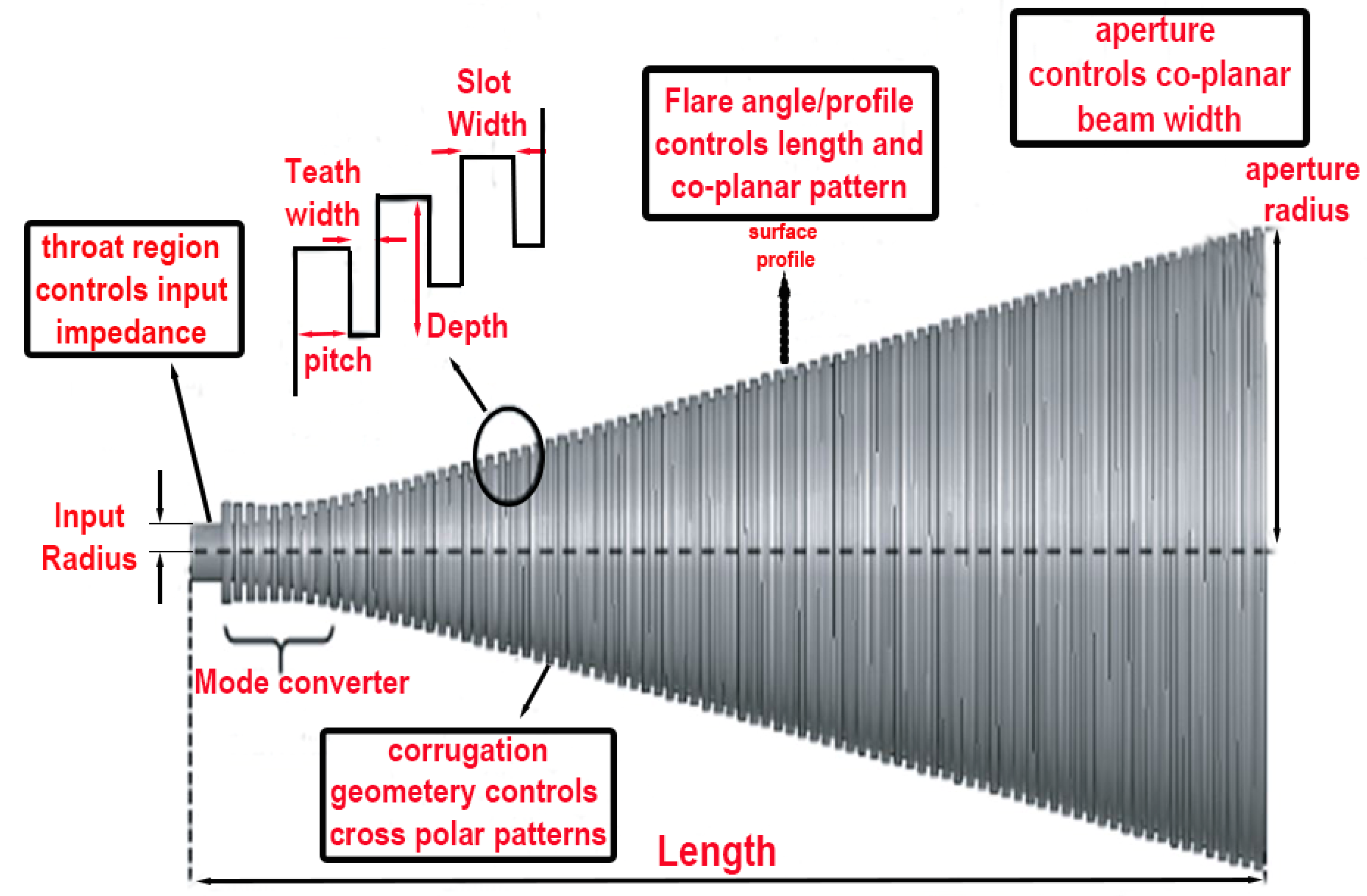
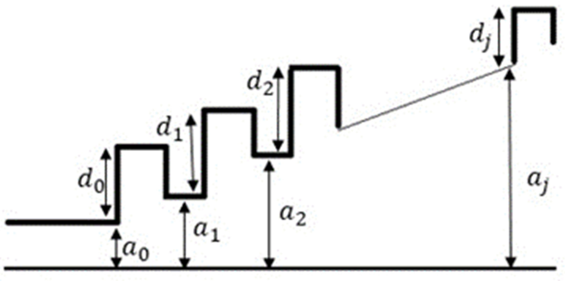
2. Design Methodology
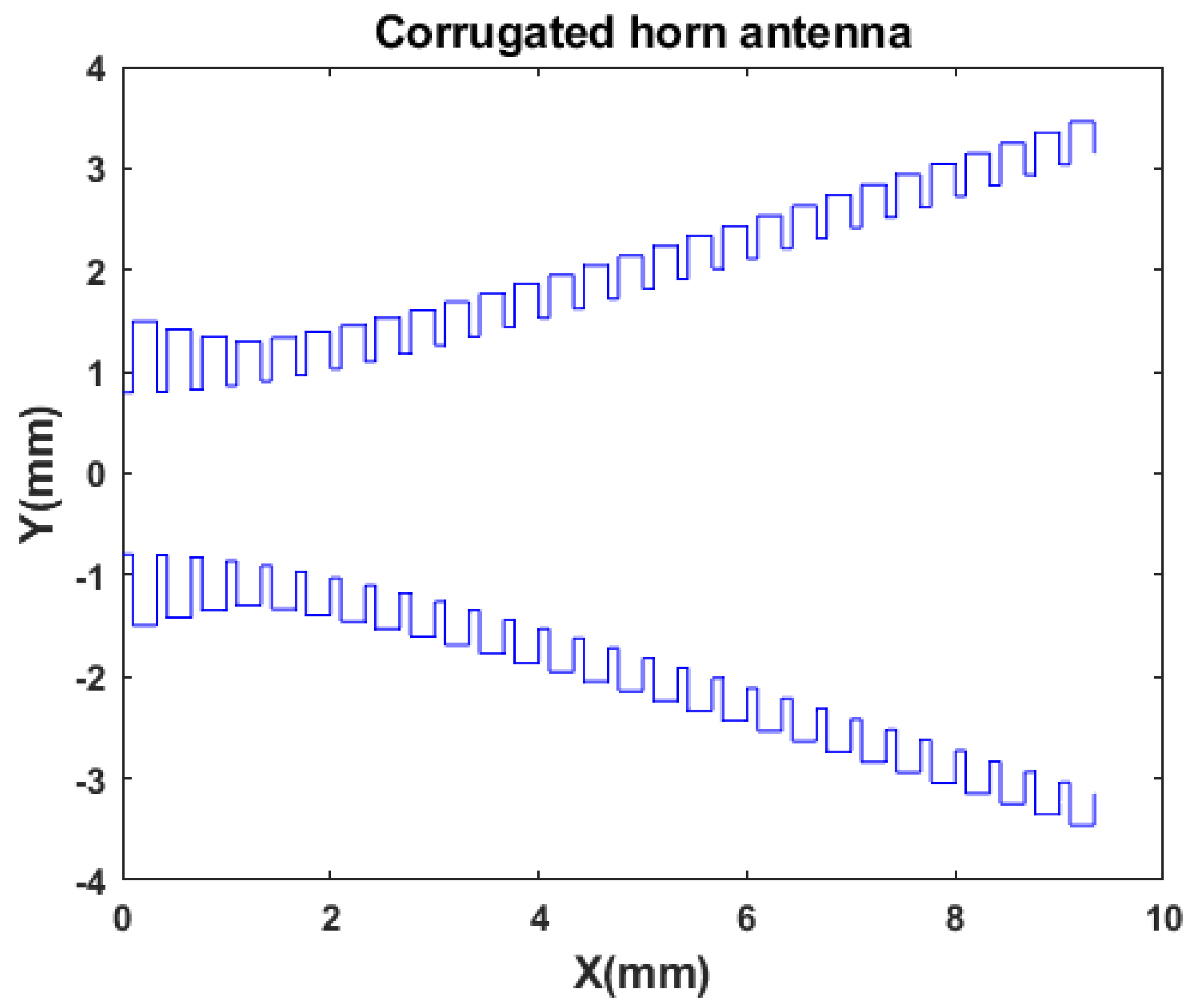
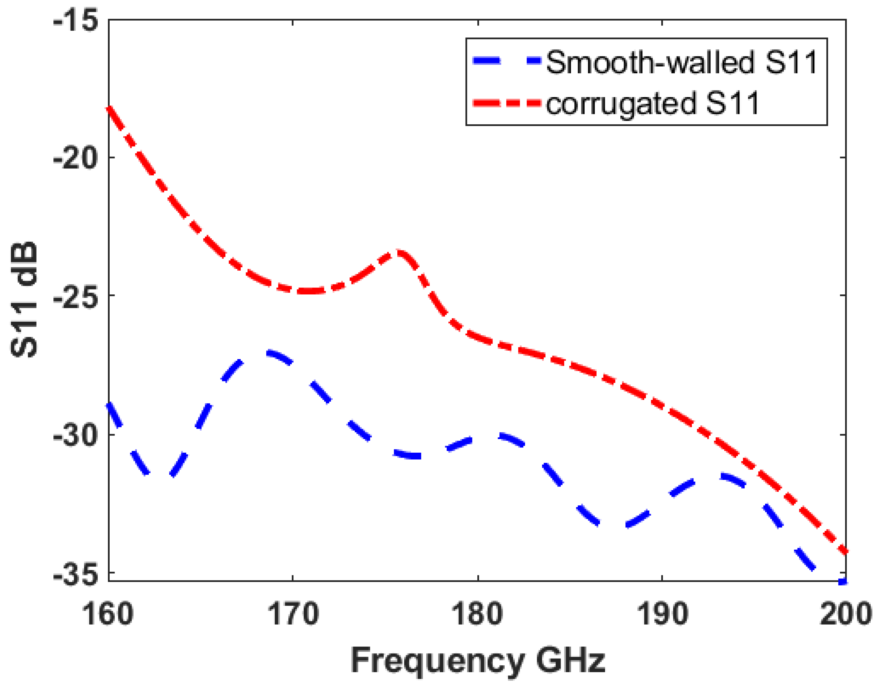
3. Simulation and Results
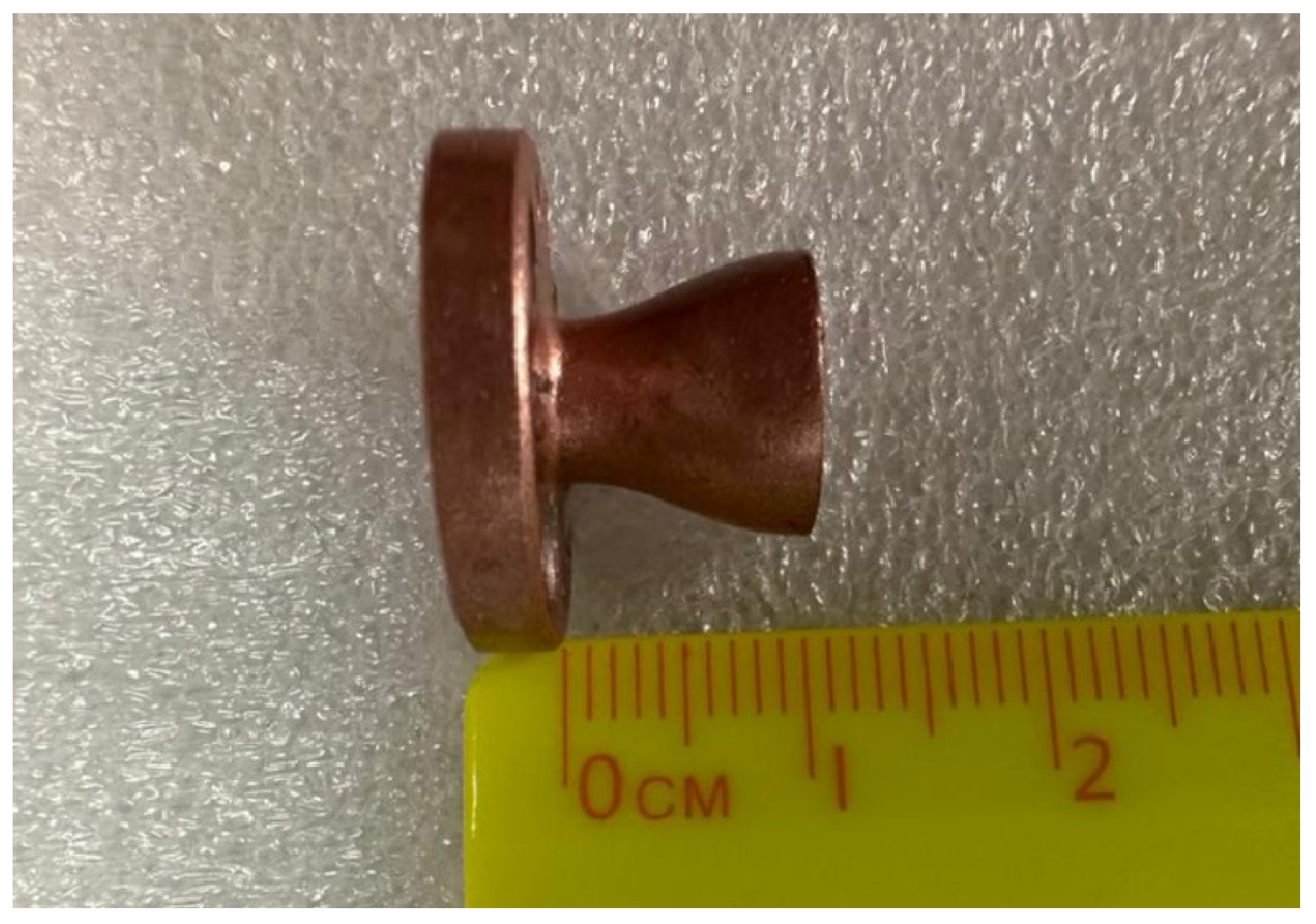
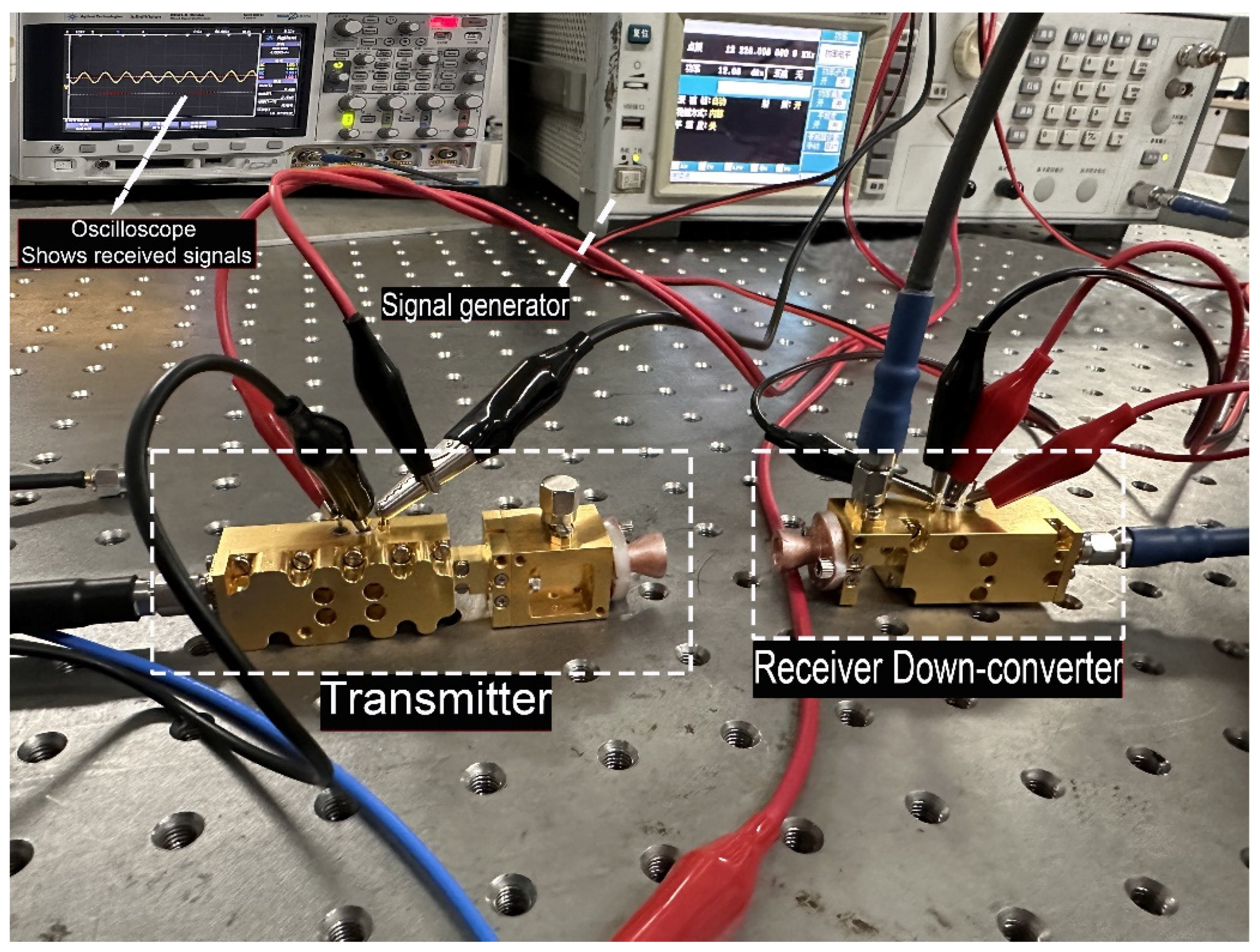
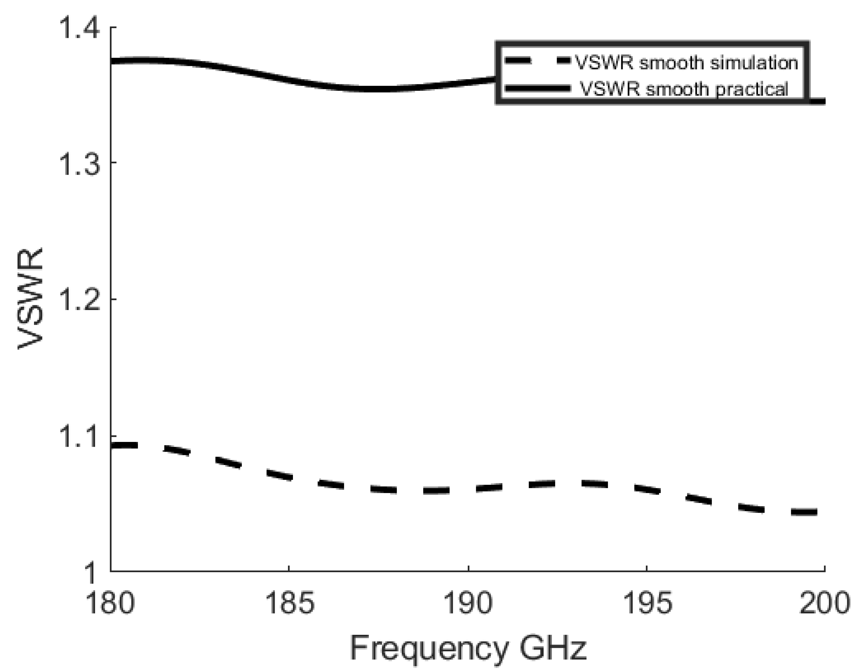
4. Smooth-Walled Horn Antenna Fabrication and Practical Results
Fabrication Process
5. Project Benefits and Future Work
6. Conclusions
Author Contributions
Funding
Conflicts of Interest
References
- Chahat, N.; Jung-Kubiak, C.; Nguyen, T. 1.9-THz Multiflare Angle Horn Optimization for Space Instruments. IEEE Trans. Terahertz Sci. Technol. 2015, 5, 914–921. [Google Scholar] [CrossRef]
- Federici, J.F.; Schulkin, B.; Huang, F.; Gary, D.; Barat, R.; Oliveira, F.; Zimdars, D. Hz imaging and sensing for security applications—Explosives, weapons and drugs. Semicond. Sci. Technol. 2005, 20, S266–S280. [Google Scholar] [CrossRef]
- Hester, J.G.; Chamberlain, J.M. The use of submillimeter and THz imaging for security applications. In Proceedings of the 2012 IEEE International Conference on Wireless Information Technology and Systems (ICWITS) and Applied Computational Electromagnetics (ACES), Maui, HI, USA, 11–16 November 2012. [Google Scholar]
- Aqlan, B.; Himdi, M.; Le-Coq, L.; Vettikalladi, H. Sub-THz Circularly Polarized Horn antenna using Wire Electrical Discharge Machining for 6G Wireless Communications. IEEE Access 2020, 8, 117245–117252. [Google Scholar] [CrossRef]
- Dhillon, S.S. The 2017 Terahertz Science and Technology Roadmap. J. Phys. D Appl. Phys. 2017, 50, 043001. [Google Scholar] [CrossRef]
- Abbosh, A.M. Horn Antenna Advantages for Ultra-Wideband Applications. IEEE Antennas Propag. Mag. 2008, 50, 113–118. [Google Scholar]
- Chen, Y.; Shen, Z.; Zhang, X. Gain Enhancement of Horn Antenna with Metasurface Lens. IEEE Trans. Antennas Propag. 2018, 66, 4160–4164. [Google Scholar]
- Al-Zayed, A.S.; Sheta, A.F. Design of Horn Antenna for Reducing VSWR and Improving Directivity. In Proceedings of the 2018 International Conference on Computer and Applications (ICCA), Doha, Qatar, 25–26 September 2018; pp. 295–299. [Google Scholar]
- James, G.L.; Henderson, A. Antenna Handbook: Volume III Applications; Van Nostrand Reinhold: New York, NY, USA, 2002. [Google Scholar]
- Pal, S.K.; Chakraborty, U.; Chattopadhyay, S. Corrugated Conical Horn Antenna with Improved Radiation Characteristics. IEEE Antennas Wirel. Propag. Lett. 2016, 15, 1492–1495. [Google Scholar]
- Mailloux, R.J. Phased Array Antenna Handbook; Artech House: Boston, MA, USA, 2005. [Google Scholar]
- Sisodia, M.L.; Sharma, G.S. Microwave Devices and Circuit Design; PHI Learning: Delhi, India, 2014. [Google Scholar]
- Alvaro, G.; Keiko, K.; Takafumi, K.; Shini’chiro, A.; Yoshinori, U. Terahertz Corrugated Horns (1.25–1.57 THz): Design, Gaussian Modeling, and Measurements. IEEE Trans. Terahertz Sci. Technol. 2017, 7, 1. [Google Scholar] [CrossRef]
- Mahdi, O.; Mohammad, S.A. Corrugated SIW K band horn antenna. AEU–Int. J. Electron. Commun. 2014, 68, 12. [Google Scholar] [CrossRef]
- Kovitz, J.M.; Manohar, V.; Rahmat-Samii, Y. A Spline-Profiled Conical Horn Antenna Assembly Optimized for Deployable Ka-Band Offset Reflector Antennas in CubeSats. In Proceedings of the 2016 IEEE International Symposium on Antennas and Propagation (APSURSI), Fajardo, PR, USA, 26 June–1 July 2016. [Google Scholar] [CrossRef]
- Hammar, A.; Karandikar, Y.; Forsberg, P.; Emrich, A.; Stake, J. A 340 GHz High Gaussicity Smooth Spline Horn Antenna for the STEAMR Instrument. In Proceedings of the 2014 IEEE Antennas and Propagation Society International Symposium (APSURSI), Memphis, TN, USA, 6–11 July 2014. [Google Scholar] [CrossRef]
- Shi, W.; Hu, C.; Wang, L.-Z. Design and Performance Analysis of a Conical Corrugated Horn Antenna for CubeSat Millimeter-Wave Radiometer. Sensors 2019, 19, 2620. [Google Scholar] [CrossRef]
- Granet, C.; James, G.L. Design of Corrugated horns: A primer. IEEE Antennas Propag. Mag. 2009, 47, 76–84. [Google Scholar] [CrossRef]
- Albani, M.; Sabbadini, M. Design and Testing of Corrugated Horn Antennas for Space Applications. IEEE Trans. Antennas Propag. 2019, 67, 2659–2669. [Google Scholar]
- Salim, M.M.; Azim, R.T.; Islam, M.S.; Islam, M.T.; Misran, N. Design of a Wideband Corrugated Horn Antenna with Improved Radiation Characteristics for Remote Sensing Applications. Electronics 2020, 9, 2007. [Google Scholar] [CrossRef]
- Ghasemi, M.; Oraizi, H. A new design for wideband corrugated horn antenna using hybrid optimization algorithm. Int. J. RF Microw. Comput.-Aided Eng. 2021, 31, e22719. [Google Scholar] [CrossRef]
- MacPhie, R.H. Horn antennas for space applications. In Antenna Engineering Handbook; Volakis, J.L., Ed.; McGraw-Hill: New York, NY, USA, 2007. [Google Scholar]
- Jensen, M.A.; Johnson, J.W.; Rahmat-Samii, Y. Electromagnetic scattering by objects above or below a plane surface. IEEE Trans. Antennas Propag. 2000, 26. [Google Scholar]
- Batchelor, J.C.; Brown, A.; Clarke, A.; Griffiths, D. A broadband dual-polarized corrugated horn for the 15–37 GHz band. IEEE Trans. Antennas Propag. 2001, 49, 20–26. [Google Scholar]
- Wu, K. Antenna Design and Fabrication for 5G Communication Systems. Electronics 2020, 9, 992. [Google Scholar] [CrossRef]
- Shi, W.; Hu, C.; Wang, L.-Z. Smooth-walled corrugated horn antenna for CubeSat THz spectrometer payload in planetary water detection missions. Prog. Electromagn. Res. Lett. 2020, 85, 101–108. [Google Scholar] [CrossRef]
- Granet, C.; James, G.L.; Bolton, R.; Moorey, G. A Smooth-Walled Spline-Profile Horn as an Alternative to the Corrugated Horn for Wide Band Millimeter-Wave Applications. IEEE Trans. Antennas Propag. 2004, 52, 848–854. [Google Scholar] [CrossRef]
- Campa, R.; Szocik, K.; Brddock, M. Why space colonization will be fully automated. Acta Astronaut. 2019, 143, 162–171. [Google Scholar] [CrossRef]
- Khan, N.S.; Hu, W.; Xie, Z.; Wu, J. Design of a dual-band circularly polarized corrugated horn antenna for 5G and millimeter wave applications. IEEE Trans. Antennas Propag. 2020, 68, 2005–2010. [Google Scholar]
- Robinson, J.; Sinton, S.; Rahmat-Samii, Y. Particle swarm, genetic algorithm, and their hybrids: Optimization of a profiled corrugated horn antenna. In Proceedings of the 2002 IEEE Antennas and Propagation Society International Symposium, San Antonio, TX, USA, 16–21 June 2002. [Google Scholar] [CrossRef]
- Rastinasab, V.; Hu, W.; Tahmasebi, M.K. Water Recognition on the Moon by Using THz Heterodyne-Spectrometer for Identifying the Appropriate Locations to Extract Water for Providing Oxygen for Breathing and Fuel for Spaceships’ Propulsion on the Moon with CubeSat. Aerospace 2021, 8, 186. [Google Scholar] [CrossRef]
- Bruno, R.; Christophe, S. Carbon-rich icy moons and dwarf planets. Earth Planet. Sci. Lett. 2023, 612, 15. [Google Scholar] [CrossRef]


| Parameter | Optimized Values (mm) |
|---|---|
| 0.4777 | |
| L | 6 = 9.99 |
| P | = 0.3331 |
| 0.7 | |
| W | 0.23317 |
| 3.2477 | |
| 5 |
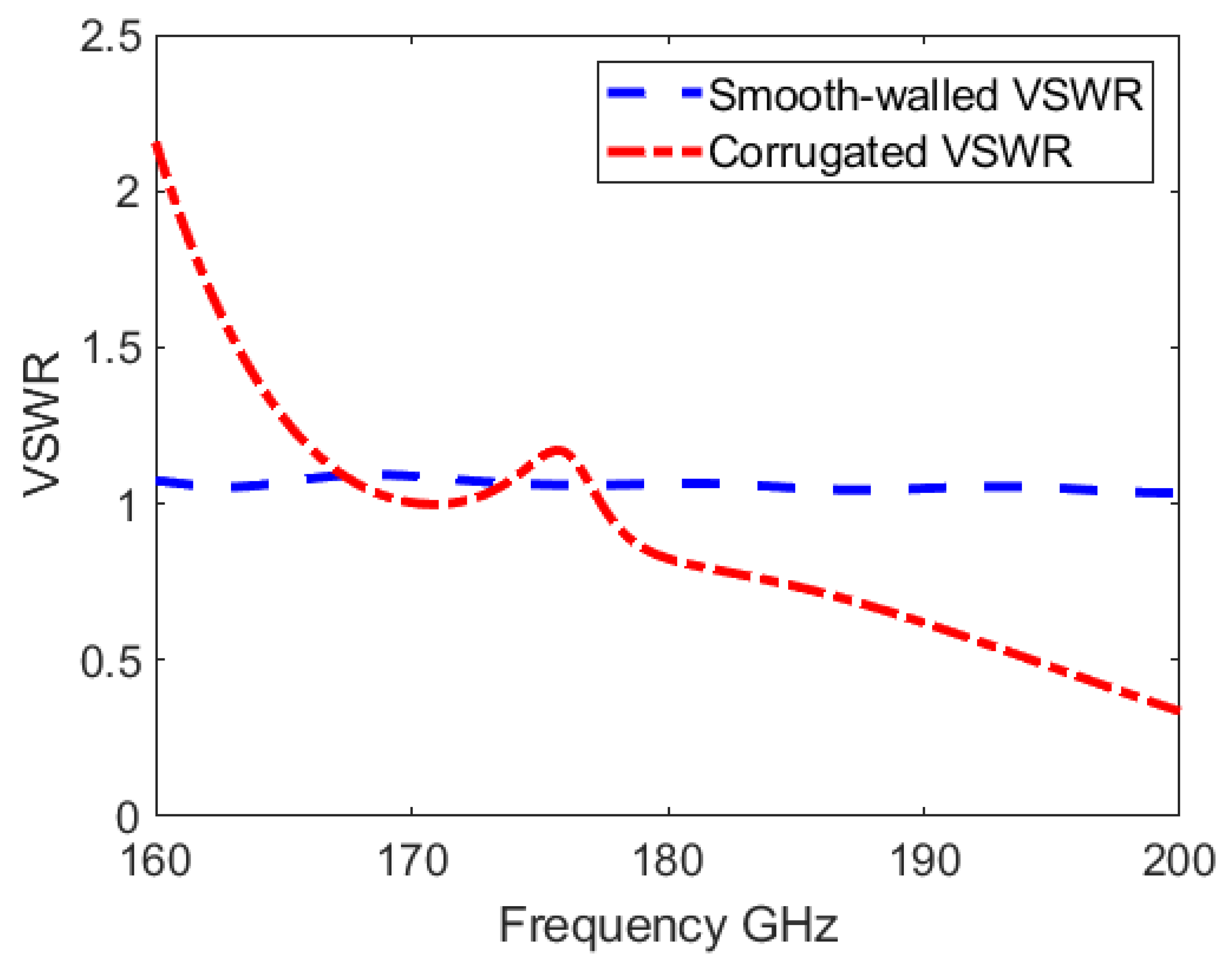
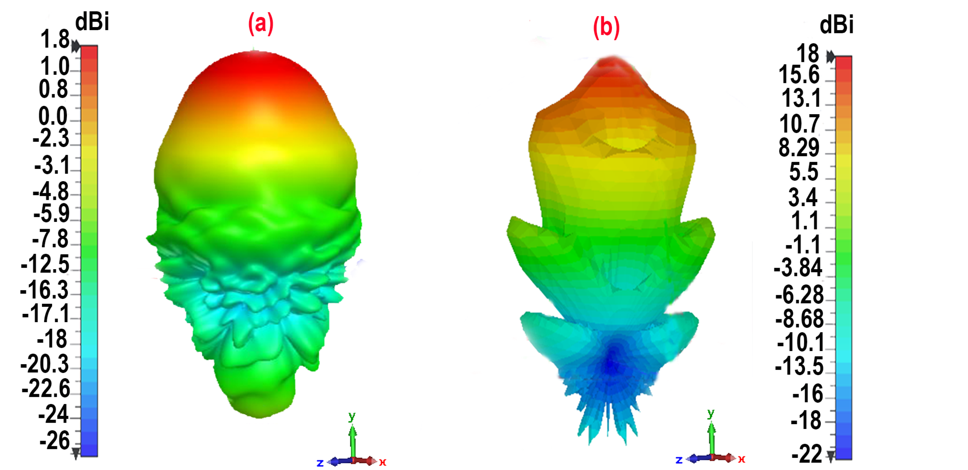
| Antenna Type | dB | VSWR | Gain dB |
|---|---|---|---|
| corrugated | −5 to −35 | 2.23 to 0.35 | 1.4 |
| Smooth | −27 to −36 | 1.01 | 18 |
| fabricated | −26 to −30 | 1.45 | -- |
Disclaimer/Publisher’s Note: The statements, opinions and data contained in all publications are solely those of the individual author(s) and contributor(s) and not of MDPI and/or the editor(s). MDPI and/or the editor(s) disclaim responsibility for any injury to people or property resulting from any ideas, methods, instructions or products referred to in the content. |
© 2023 by the authors. Licensee MDPI, Basel, Switzerland. This article is an open access article distributed under the terms and conditions of the Creative Commons Attribution (CC BY) license (https://creativecommons.org/licenses/by/4.0/).
Share and Cite
Rastinasab, V.; Hu, W.; Shahzad, W.; Abbas, S.M. CubeSat-Based Observations of Lunar Ice Water Using a 183 GHz Horn Antenna: Design and Optimization. Appl. Sci. 2023, 13, 9364. https://doi.org/10.3390/app13169364
Rastinasab V, Hu W, Shahzad W, Abbas SM. CubeSat-Based Observations of Lunar Ice Water Using a 183 GHz Horn Antenna: Design and Optimization. Applied Sciences. 2023; 13(16):9364. https://doi.org/10.3390/app13169364
Chicago/Turabian StyleRastinasab, Vahid, Weidong Hu, Waseem Shahzad, and Syed Muzahir Abbas. 2023. "CubeSat-Based Observations of Lunar Ice Water Using a 183 GHz Horn Antenna: Design and Optimization" Applied Sciences 13, no. 16: 9364. https://doi.org/10.3390/app13169364