Article

Design of Wideband Decoupling Antenna Array for 5G Smartphones at N77/N78/N79/WLAN 5 GHz Bands

1
School of Electronic and Information Engineering, Lanzhou Jiaotong University, Lanzhou 730070, China
2
School of Mechanical and Electrical Engineering, Lanzhou Jiaotong University, Lanzhou 730070, China
3
Engineering Research Center of Integrated Circuit Packaging and Testing, The Ministry of National Education, Tianshui 741000, China
4
School of Electronic Information and Electrical Engineering, Tianshui Normal University, Tianshui 741000, China
*
Author to whom correspondence should be addressed.
Appl. Sci. 2023, 13(16), 9370; https://doi.org/10.3390/app13169370
Submission received: 21 July 2023 / Revised: 5 August 2023 / Accepted: 16 August 2023 / Published: 18 August 2023

Abstract

:
We propose a broadband decoupled antenna pair for 5G mobile terminals. The broadband decoupled design of this antenna pair is based on the characteristic mode theory (CMA) and defective ground structure. First, CMA is applied to obtain the characteristic current distribution of the antenna, then the characteristic current sensitive regions are optimized to make the antenna introduce new modes and obtain a wide bandwidth. After that, an antenna pair is added with defective ground structure to obtain a wideband decoupled antenna pair that has small size and high isolation. Next, an eight-element MIMO antenna system is constructed with the obtained broadband decoupled antenna pair, and a composite decoupling technique consisting of defective ground structure (DGS) and decoupling strip is applied to the two antenna pairs on the same side of the bezel to improve the isolation. The simulation and prototype test results show that the eight-element MIMO antenna with −10 dB bandwidth of 3.28~5.85 GHz mainly covers the N77/N78/N79/WLAN 5 GHz band, and the antenna pair are only 1.6 mm apart with good isolation (−16.7 dB), the ECC is less than 0.01, and it has a good total efficiency at the main operating frequency. Finally, the effect of a user’s hand on the antenna is briefly analyzed to verify the robustness of the proposed MIMO antenna system.

1. Introduction

The informatization needs of human society’s production and life have accelerated the development and improvement of mobile communication systems. Since 1973, mobile communication systems have gone through analog telecommunication systems, SISO, MIMO, and massive MIMO, and the current fifth-generation mobile communication system (5G) pursues the characteristics of wide bandwidth, large capacity, high speed, low latency, and high reliability. The 5G frequency bands are mainly divided into a sub-6 GHz band (FR1) and millimeter-wave band above 24 GHz (FR2) [1]. The sub-6 GHz band (FR1) has better coverage area and smaller propagation loss than the millimeter-wave band (FR2), but it is not as good as the millimeter-wave band in terms of transmission speed and security, and the spectrum resources are relatively tight. However, due to the serious path loss and expensive deployment cost of millimeter-wave technology, the sub-6 GHz band is more practical at this stage. The foregoing suggests that multiple-input multiple-output (MIMO) technology makes the application of the sub-6 GHz band in 5G a reality due to its feature of effectively increasing the channel capacity of the communication system in a rich scattering environment [2]. According to the requirements of 5G-related protocols, sub-6 GHz mobile terminal MIMO systems require at least 6–8 antenna elements. However, integrating multiple antenna elements within a compact mobile terminal will result in significant mutual coupling between antenna elements. Mutual coupling leads to decreased antenna isolation and increased envelope correlation coefficient, and then channel capacity is reduced and communication quality deteriorates [3]. Therefore, how to design broadband high-isolation terminal antennas with compact size has received increasing attention.
Previously proposed decoupling techniques mainly include loaded parasitic elements (PEs) [4,5,6], defective ground structures (DGSs) [7,8,9], neutralization lines (NLs) [10,11,12], diversity technique [13,14,15], common ground plane higher-order mode [16], self-curing decoupling technique [17,18], and decoupling network [19]. These techniques have been proven to be effective in solving the mutual coupling problem of traditional MIMO antennas. However, when applied to eight-element antenna arrays and broadband antenna decoupling, they face problems such as decoupling only 2–3 elements or part of the frequency range. In recent years, some decoupled antennas covering sub-6 GHz n77 (3300–4200 MHz), n78 (3300–3800 MHz), n79 (4400–5000 MHz) have been proposed [20,21,22,23,24,25,26,27,28,29,30,31,32]. The orthogonal pattern dual-antenna shared radiator design is used in [20] to achieve 3.3~5.0 GHz impedance bandwidth (−6 dB) with a high isolation of 21 dB. This decoupling is so cleverly designed that it does not require any external decoupling structure, but its bandwidth coverage is small. In [22], by placing eight antenna elements orthogonally at the four corners of the model and decoupling them with a 7.8 mm short neutralizing line, the dual-band impedance bandwidths of 3.1–3.85 GHz and 4.8–6 GHz are achieved. This design is very compact, and it cleverly utilizes the space in the four right-angle positions of the smartphone, but the broadband performance is less than ideal and does not fully cover the n77 and n79 bands. In [23], an ideal impedance bandwidth of 3.3~5.6 GHz was obtained by coupling the radiating branch with a T-shaped feeder branch, and a high isolation of 15 dB was obtained by introducing a T-shaped neutralizing line structure. However, the antenna unit and decoupling structure in this design almost completely occupy the two longer-side bezels. [29] The bandwidth is expanded by characteristic mode theory, and the isolation is enhanced by introducing a multiple defect ground structure (DGS) to achieve an impedance bandwidth of 3.23~5.24 GHz (−10 dB), and a high isolation of 17.24 dB is achieved at the antenna pairs with a 2 mm interval, but the isolation between Ant 2 and Ant 3 still needs to be further improved. A flexible and transparent broadband four-element MIMO antenna with a connected ground plane is innovatively proposed in [31]. The design uses flexible conductive oxide material AgHT-4 and Melinex substrate to obtain optical transparency with −10 dB impedance bandwidth from 2.21–6 GHz (92.32%). Due to its flexible and transparent nature, it can be used in scenarios where aesthetics are important, such as glass. The above shows that wider-frequency bands allow the combination of antennas operating in different frequency bands, effectively saving space inside the terminal. However, in the process of broadband antenna design, different decoupling structures will affect the overall structure and performance of the antenna system, and how to achieve a good balance between antenna performance and compact size is a challenging task.
In this paper, a base antenna pair is first constructed, and CMA is applied to capture the important patterns of the base antenna pair. The modal significance, modal weighting coefficient, and characteristic currents of each mode are analyzed and used to optimize the antenna structure. This process is repeated to gradually evolve the antenna pair and thus expand the bandwidth. Meanwhile, in order to make the antenna pairs as compact as possible while ensuring the isolation, we add a strip-shaped defective ground structure in the middle of the antenna pairs and utilize the band elimination property of the defective ground structure to block the surface current on the common ground plane from one antenna to the other antenna, so as to obtain good isolation in the broadband range. Second, we utilize the obtained broadband decoupled antenna pairs to construct an eight-element MIMO antenna system, and apply the complex decoupling structure composed of the defected ground and the decoupling strips to decouple the two antenna pairs that are more seriously affected by the mutual coupling, which significantly improves the isolation between the two antenna pairs. In addition, we simulate and prototype the eight-element MIMO antenna system to verify the performance of the antenna system. Finally, we also simulate the effect of a user’s hand on the antenna system to verify the robustness of the antenna system. The results show that the antenna system largely covers the n77/n78/n79 and WLAN 5 GHz bands, with good isolation in the full operating band, and the performance meets the 5G terminal antenna requirements.

2. Design and Evolution of Antenna Systems
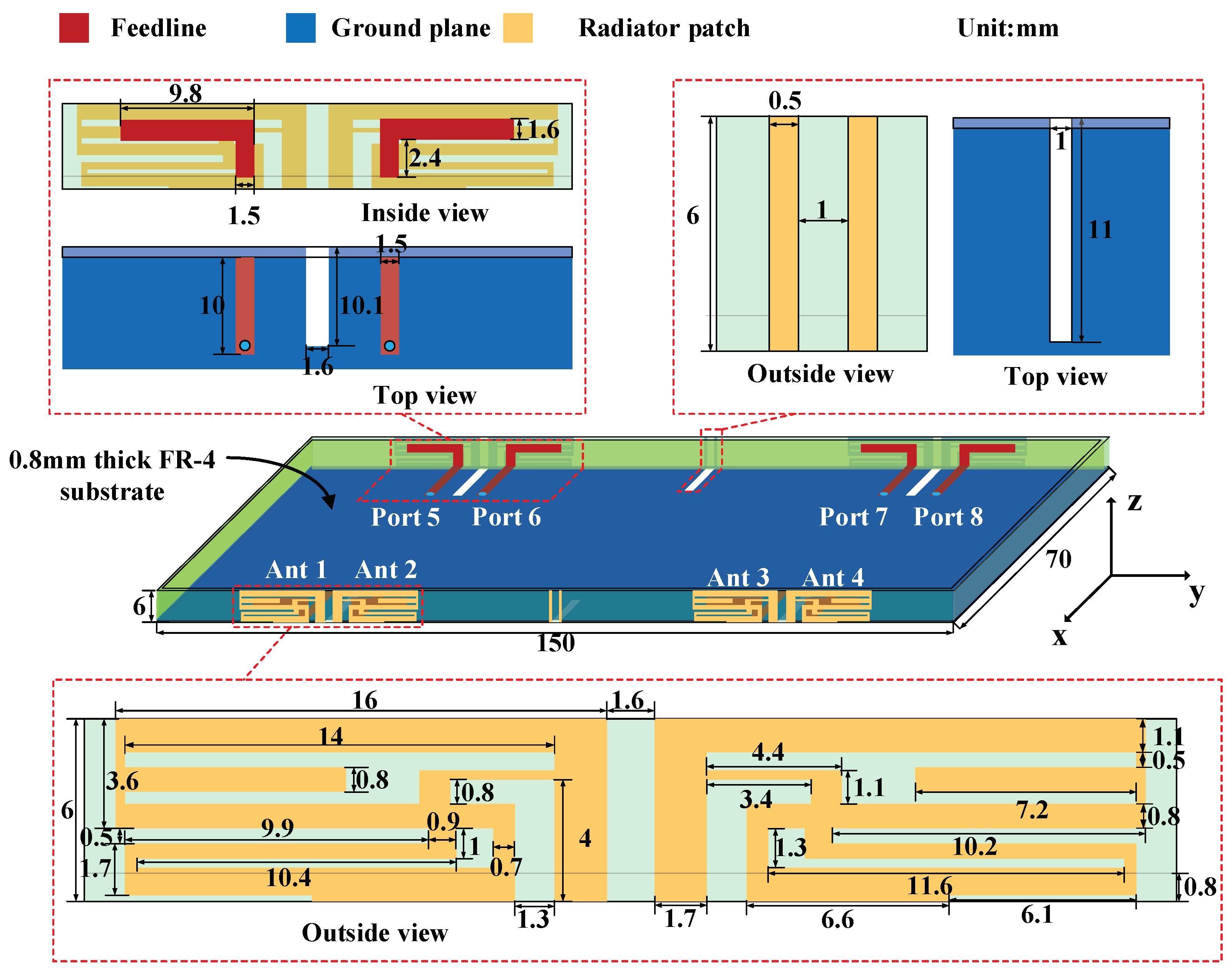
2.1. Configuration

As shown in Figure 1, the system consists of a ground plane of 150 mm × 70 mm with a ring bezel of height 6 mm. The thickness of the substrate is 0.8 mm, the substrate material is FR-4, the relative permittivity is 4.4, the relative permeability is 1, and the loss tangent is 0.02. The antenna element consists of a coupled-feeding structure formed by the inner L-type branch of the substrate and the external radiators of the bezel. The use of coupled-feeding structure is equivalent to adding an equivalent capacitance, which helps to expand the bandwidth. In addition, fine-tuning the geometry of the L-shaped coupling-fed branch can easily realize the impedance matching. Two antenna elements are symmetrically placed to form an antenna pair. To improve the isolation between the antenna pairs, a strip-shaped DGS is etched on the ground plane at the center of the antenna pairs. To improve the isolation between the antenna elements on the adjacent side of the two antenna pairs, the same strip-shaped DGS is etched in the middle of the long side of the system, and two decoupling strips are extended from the ground plane to the frame.

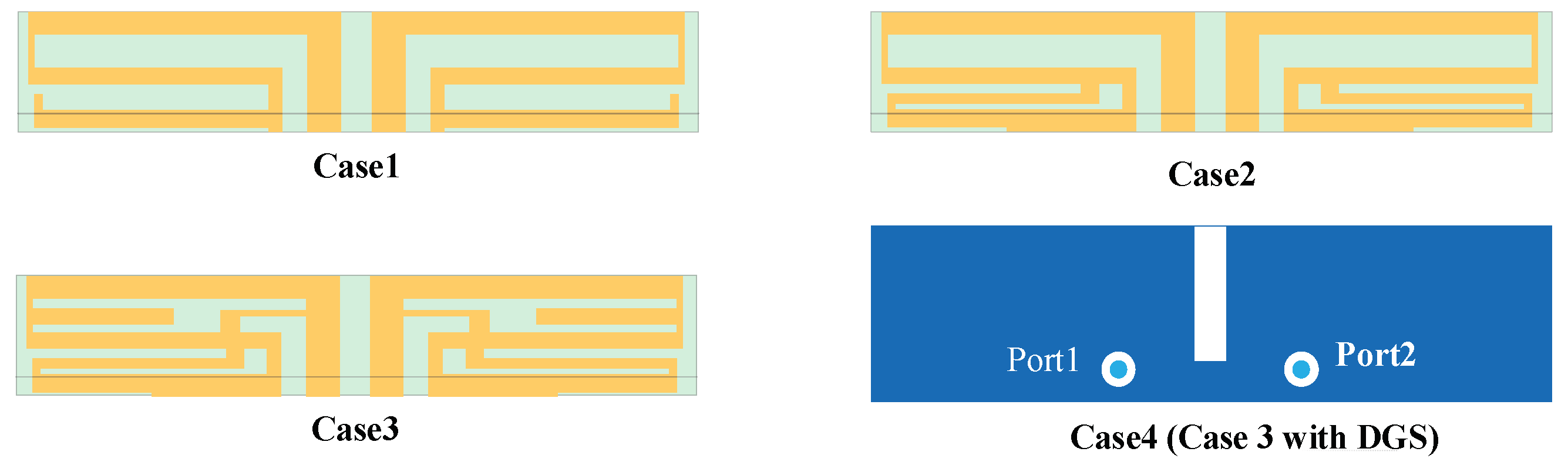
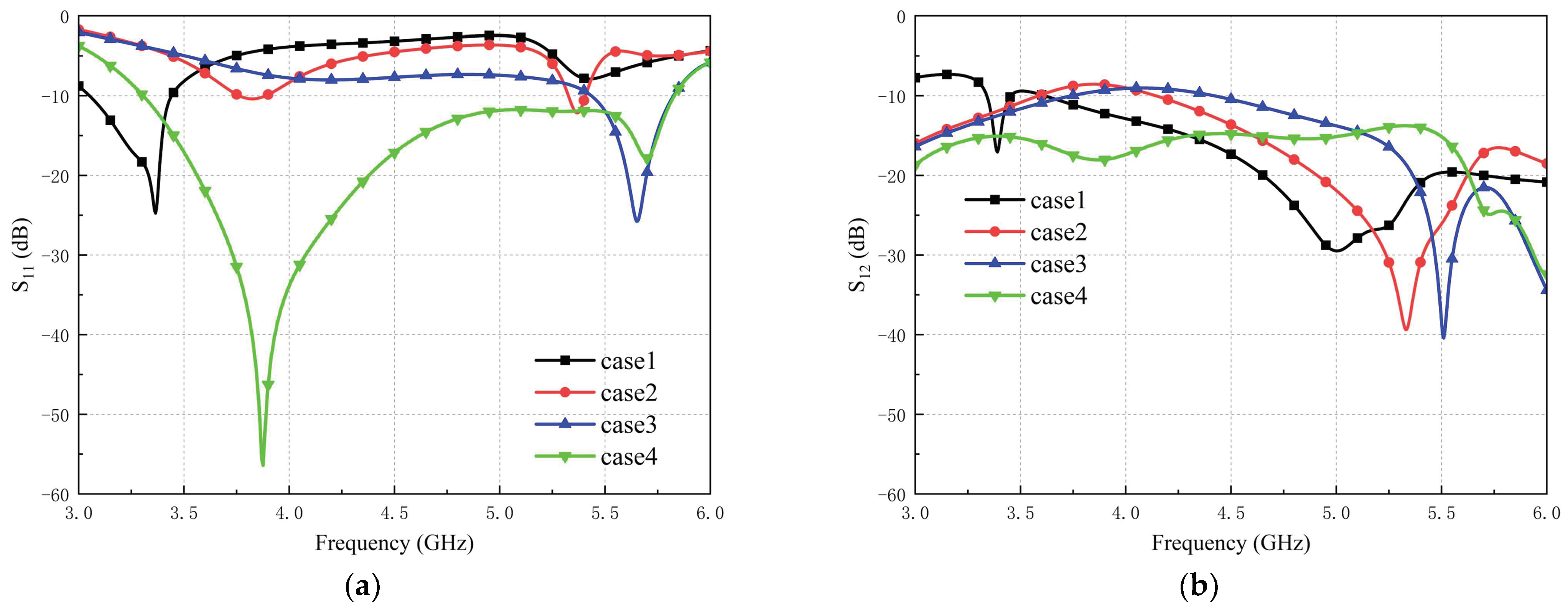
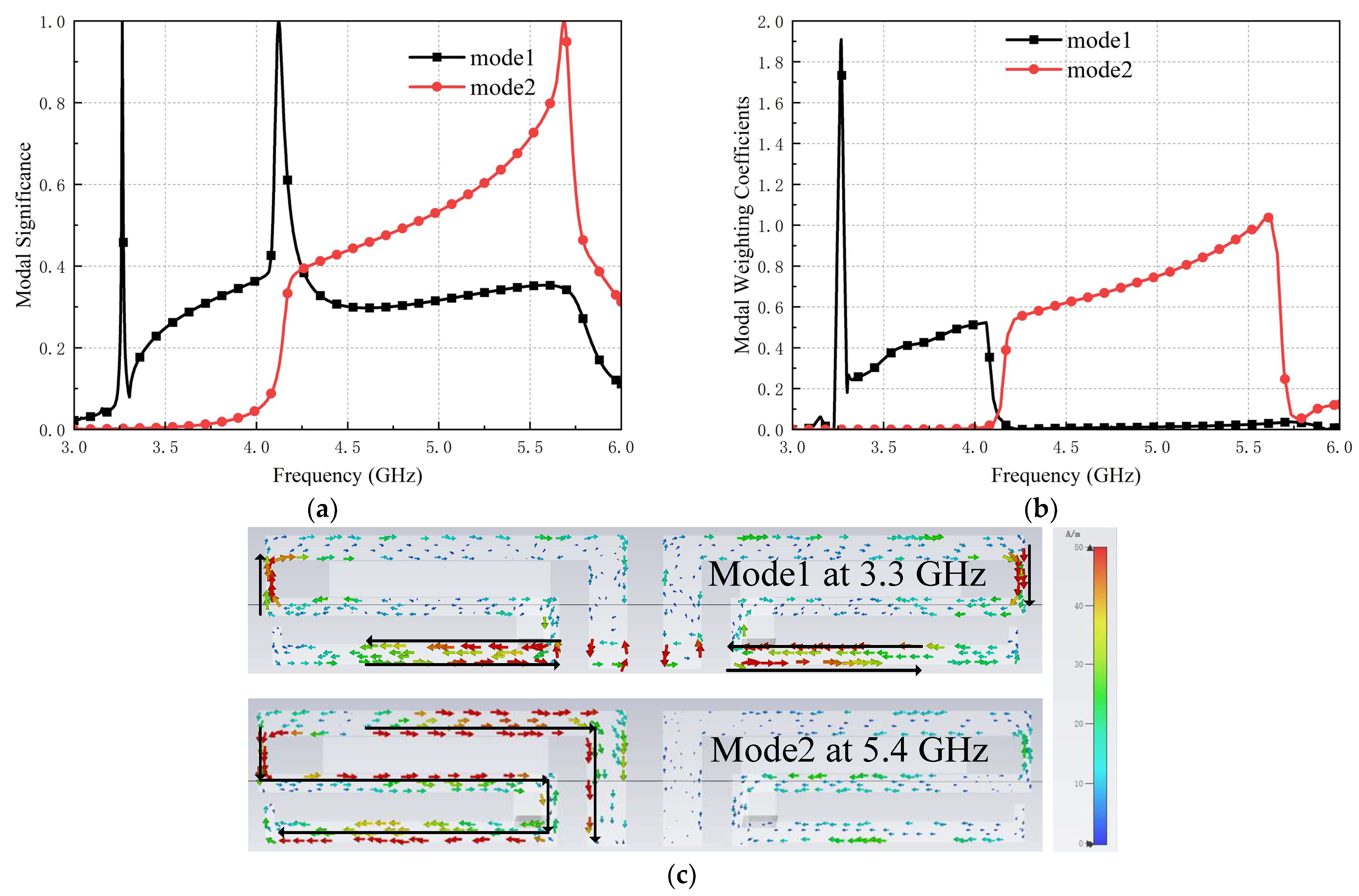
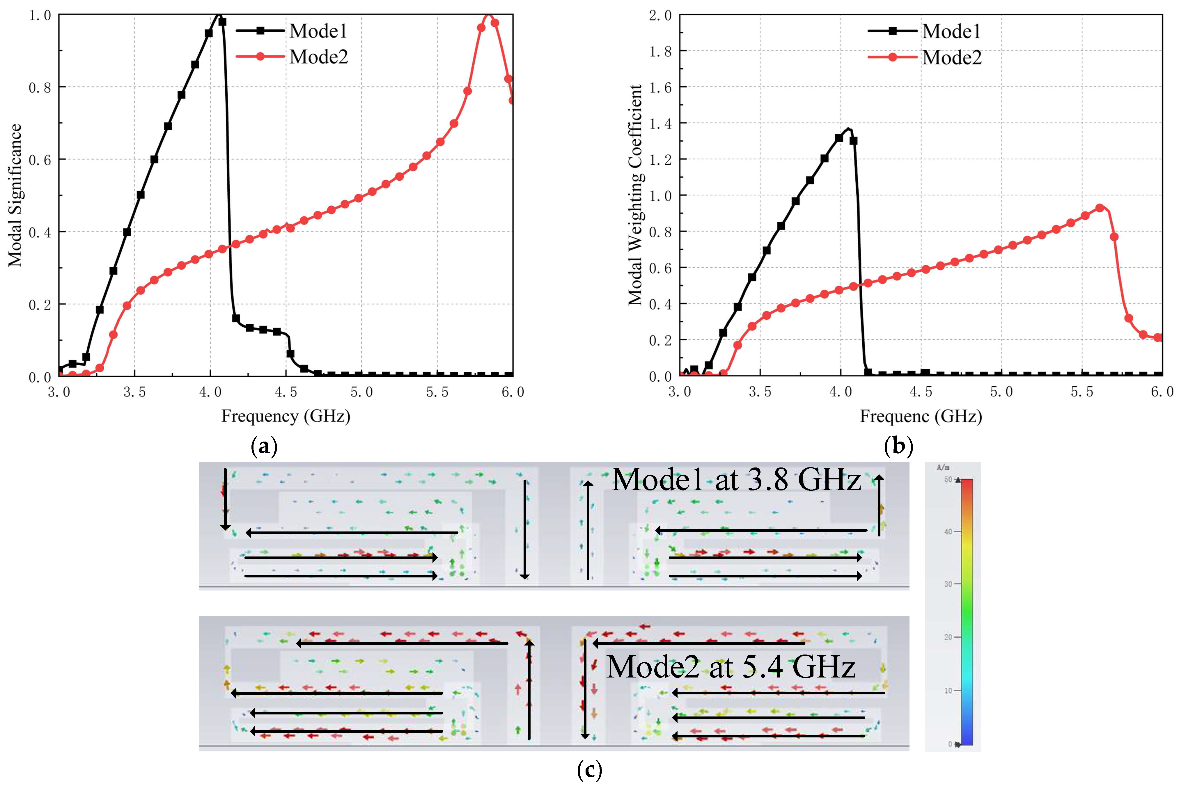
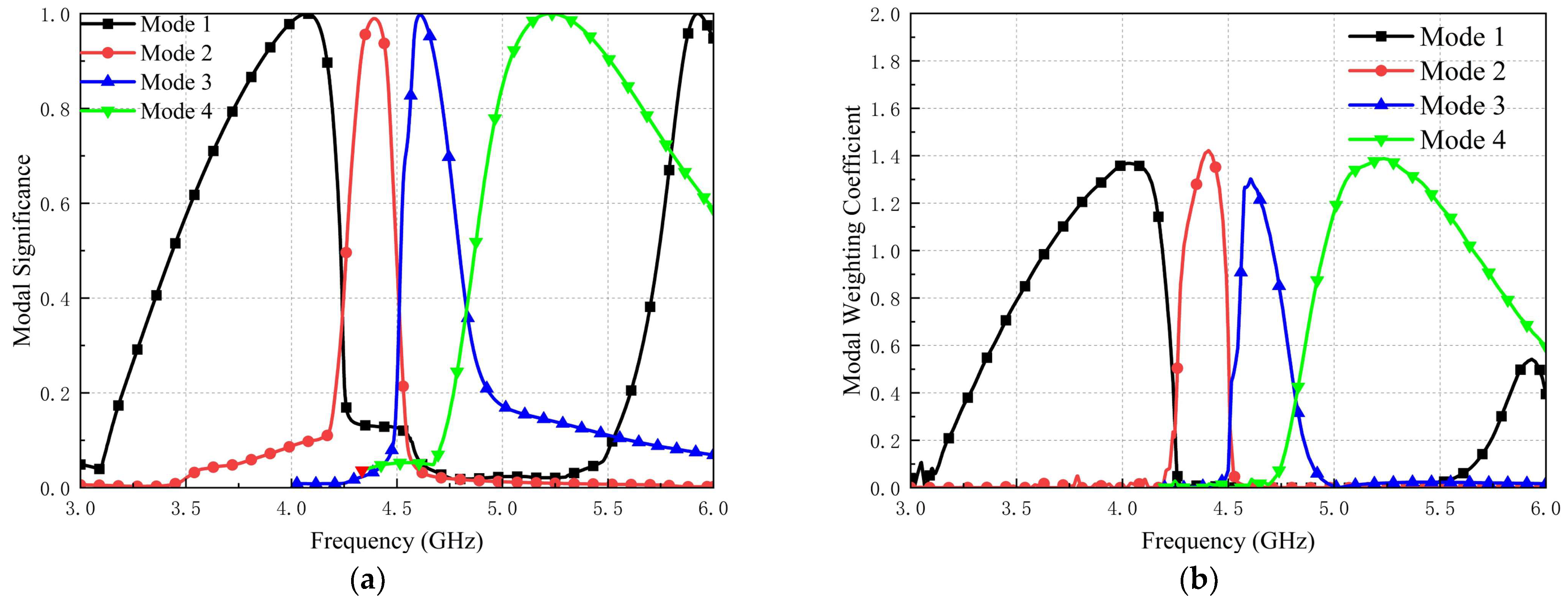
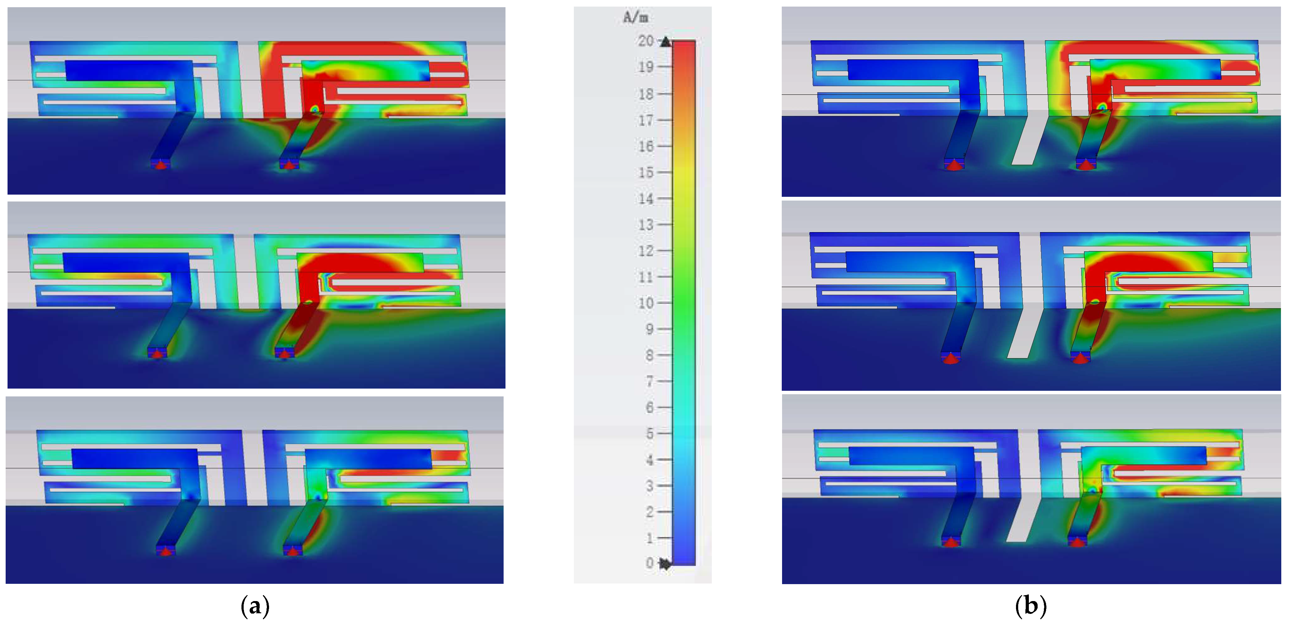
2.2. Design Process and Analysis

Since the characteristic mode theory can reveal the resonant modes of the object itself and is independent of excitation, it has received widespread attention in antenna design. In this study, the bandwidth expansion process adopts CMA. By capturing different modes and observing the corresponding characteristic current distributions, the geometry of the antenna pair is optimized at the more sensitive parts of the characteristic currents. A new mode is introduced to make the modes better excited. The evolution of the antenna pair is shown in Figure 2. Modal significance (MS) is used to indicate the potential of each mode to be excited under each geometry during the evolution of the antenna pair. The modal weighting coefficient (MWC) evaluates the extent to which the modes or combinations of modes are effectively excited. Due to the symmetry of the structure, the evolutionary process of the antenna pair is built on a quarter of the substrate with the bezel (75 mm × 35 mm), and only port 1 is analyzed for the excitation simulation. The simulation results of the reflection and transmission coefficients of the evolution process are shown in Figure 3.
The basis for bandwidth expansion is an S-shaped dual-frequency antenna pair (Figure 2, Case 1). The MS of Case 1 is shown in Figure 4a. Mode 1 and mode 2 do not form a broadband mode but have the potential to form a broadband mode. MWC shows (Figure 4b) that mode 1 and mode 2 are effectively excited at 3.3 GHz and 5.4 GHz, respectively. Figure 4c shows that the characteristic current of mode 1 is mainly concentrated in the part of the patch near the common ground plane, and mode 2 forms two loops between the L-shaped coupled feed patch and the S-shaped external radiator. What the two characteristic currents have in common is that they are both very sensitive at the long side of the S-shaped patch near the common ground plane.
Next, to increase the broadband potential of Case 1, we extended an L-shaped patch at the end of the S-shaped radiator toward the center of the antenna pair and widened the characteristic current-sensitive part of the external radiator connected to the common ground plane (Figure 2 Case 2). Figure 5a shows the MS for both modes of Case 2. The variation of MS shows that Case 2 possesses better broadband potential compared to Case 1. Figure 5b shows that Case 1 and Case 2 obtained better excitation at 3.5–5.7 GHz and ideal resonance near 4.0 GHz and 5.5 GHz. Figure 5c shows that due to the loading of the L-shaped patch, the original characteristic currents are redistributed. The characteristic currents in the low-frequency portion of Case 1 move away from the common ground plane and are concentrated on the new loaded L-shaped patch. This change effectively reduces the surface current between Ant 1 and Ant 2 at the edge of the common ground plane and improves the isolation between the ports of the low-frequency part. Nonetheless, Case 2 is still unable to meet the demands of 5G terminals, and the bandwidth needs to continue to be expanded.
In order to excite more modes in the same plane, we optimized the structure of the external radiator by adding a new L-shaped patch and rectangular patches, whose spatial position exactly corresponds to the L-shaped coupled feed patch (Figure 2 Case 3). This helps to improve the impedance matching of the antenna in the broadband range. Figure 6a shows the MS of Case 3, which introduces two new resonant modes near the center frequency compared to Case 2. The MS of the four modes is mostly greater than 0.7 in the frequency band of interest, and the antenna pair already has good broadband potential. Figure 6b shows that the four modes are able to be excited simultaneously by the same feed source and that mode 1 resonates with mode 4 near 5.7 GHz, producing the most significant resonance point in the 3.3–5.8 GHz range.
The tight arrangement of the antenna elements reduces the size of the antenna pair but causes the isolation of the antenna pair to become unsatisfactory. Figure 3b shows that Case 3 has the weakest isolation at 4.07 GHz with only −9.02 dB. Figure 7a shows that the surface currents of the antenna pair in the range of 3.3–5 GHz are mainly distributed at the edge of the common ground plane between Ant 1 and Ant 2, which is the main cause of mutual coupling. Therefore, we try to add a 10.1 mm long defective ground structure between Ant 1 and Ant 2 (Case 4). Figure 7b shows that the surface currents that originally flowed from Ant 1 to Ant 2 were effectively curtailed and instead distributed near the defective ground, and the surface currents near the L-shaped coupling feed patch of Ant 2 were also effectively attenuated. Figure 3b shows that the isolation of the antenna pair is significantly improved after the unfavorable surface currents are controlled, and the S12 decreases from −9.02 dB to −16.7 dB at 4.07 GHz, and the maximum value of the S12 decreases from −9.02 dB to −13.77 dB within 3.3–5.8 GHz. It suggests that the defective ground structure incorporated by Case 4 has good band elimination characteristics. On the other hand, it can be clearly observed in Figure 3a that the −10 dB impedance bandwidth of Case 4 is substantially improved compared to Case 3, which completely covers 3.3–5.83 GHz. It indicates that the defected ground structure is able to improve the impedance matching of the antenna pair while weakening the coupling.
The increase in the number of antennas can effectively enhance the capacity of the communication system, so we utilize the proposed antenna pairs to construct a MIMO antenna array. As shown in Figure 1, four antenna pairs are arranged on both sides of the bezel to form an eight-element MIMO system. Due to the increase in the size of the metal ground plane, new coupling is created between Ant 2 and Ant 3, which leads to the deterioration of the impedance matching and isolation of the antenna system. Therefore, we add a new composite decoupling structure between Ant 2 and Ant 3. The composite decoupling structure consists of an 11 × 1 mm2 strip defective ground structure with two 6 × 0.5 mm2 decoupling strips extending from the common ground plane to the bezel (Figure 1), and this composite decoupling structure can effectively isolate the common ground plane current between Ant 2 and Ant 3. Figure 8 shows that the composite decoupling structure improves the isolation between Ant 2 and Ant 3 from −7.5 dB to −12.42 dB compared to the no decoupling structure or single decoupling structure. This situation suggests that the proposed composite decoupling structure is well suited to be applied to eliminate coupling between two antenna pairs.

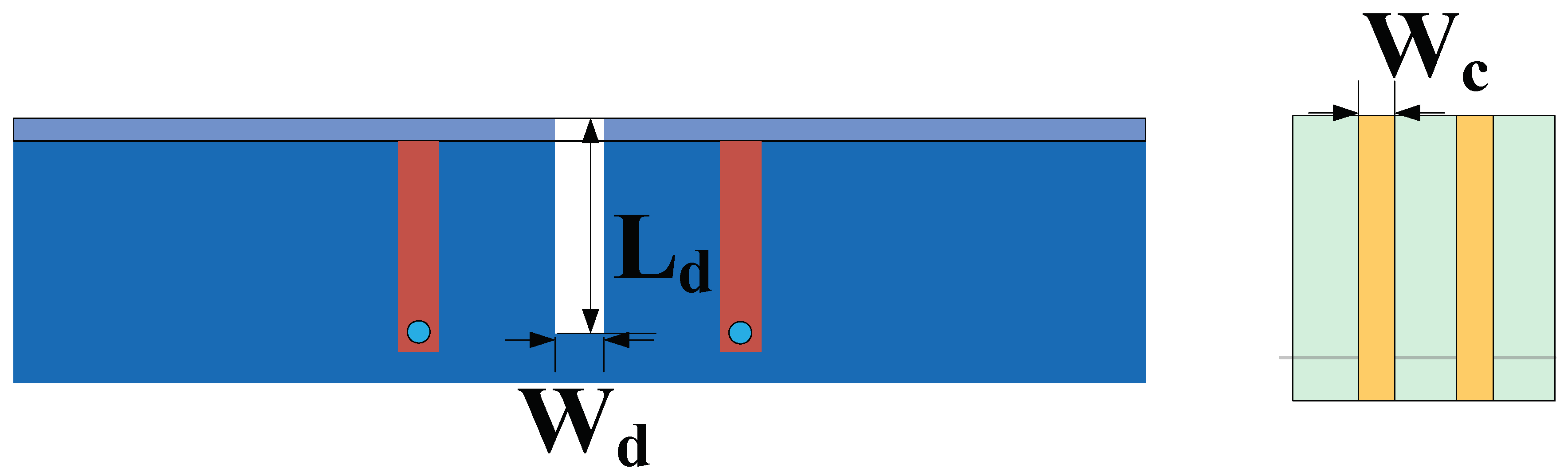
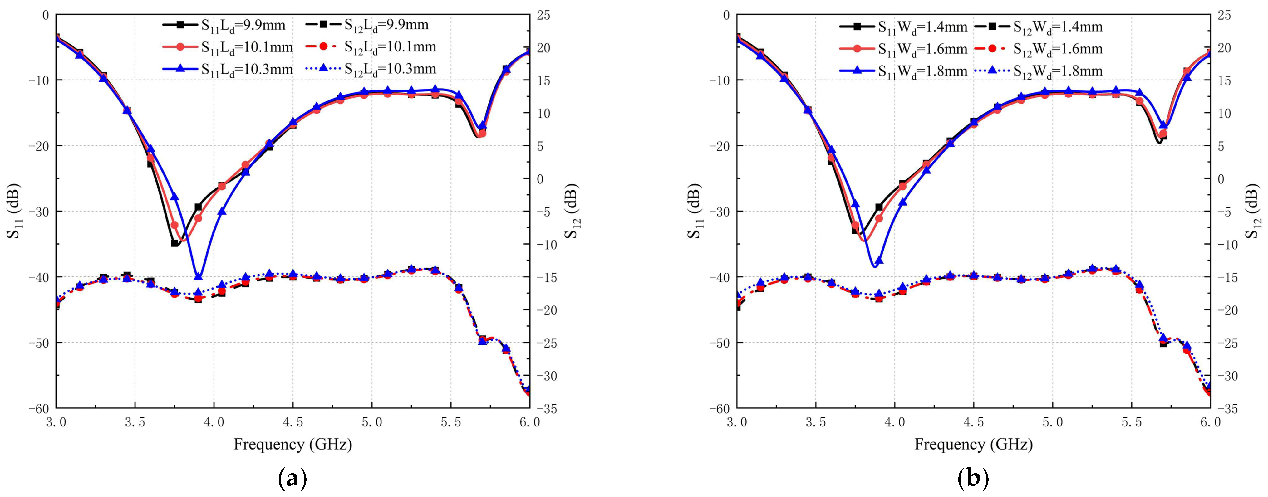
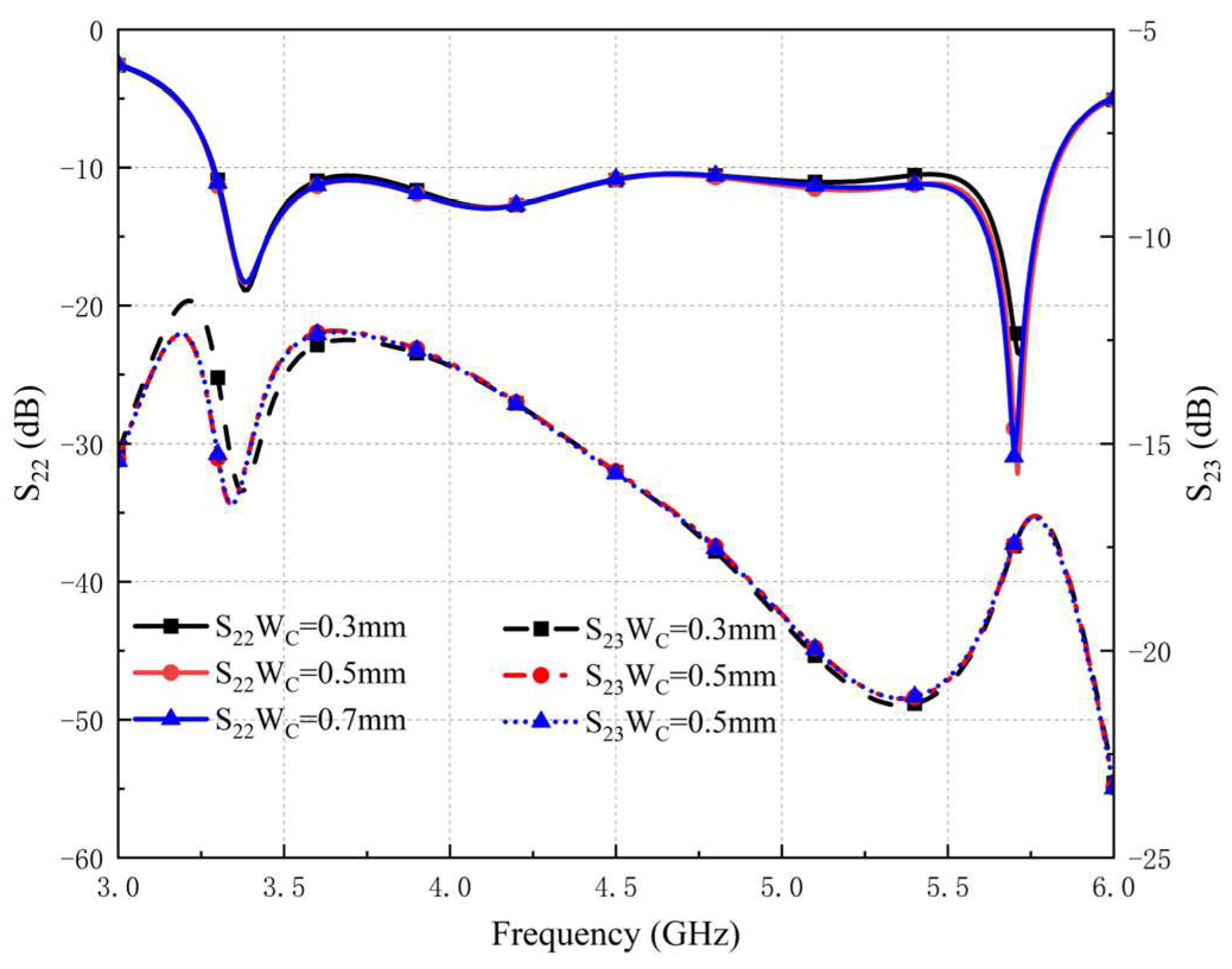
2.3. Parameter Analysis

In order to further understand the effect of the proposed decoupling structure on the antenna performance, we analyze the DGS at the center of the antenna pair and the key parameters of the composite decoupling structure. As shown in Figure 9, the length of the strip defect land at the center of the antenna pair is set to be Ld, the width to be Wd, and the width of the parasitic strip to be Wc.
Figure 10a shows that the variation of Ld has a significant effect on the band-elimination characteristics of the defected ground. As Ld increases, the isolation of the low-frequency part improves and the resonance effect is strengthened, while the isolation of the high-frequency part deteriorates and the resonance effect is weakened. When Ld exceeds 10.1, the high-frequency part S11 gradually increases, affecting the broadband performance. Figure 10b shows that the effect of Wd on the antenna is very similar to that of Ld. The isolation of the high-frequency part is slightly deteriorated when Wd exceeds 1.6 mm. In order to balance the bandwidth and isolation, a defective ground structure with a length of 10.1 mm and a width of 1.6 mm is finally chosen.
From Figure 11, we can clearly observe that the change in the value of Wc has almost no effect on the impedance matching of the antenna, which is due to the fact that the position of the composite decoupling structure is farther away from the antenna pair. When Wc is 0.3 mm, S22 approaches −10 dB near 5.5 GHz. The reflection coefficient of the high-frequency part and the transmission coefficient of the low-frequency part are improved when Wc is 0.5 mm. When Wc is more than 0.5 mm, the reflection coefficient and the transmission coefficient are almost unchanged. Therefore, we chose the parasitic band structure with a Wc of 0.5 mm.

3. Performance of the Eight-Element Antenna System

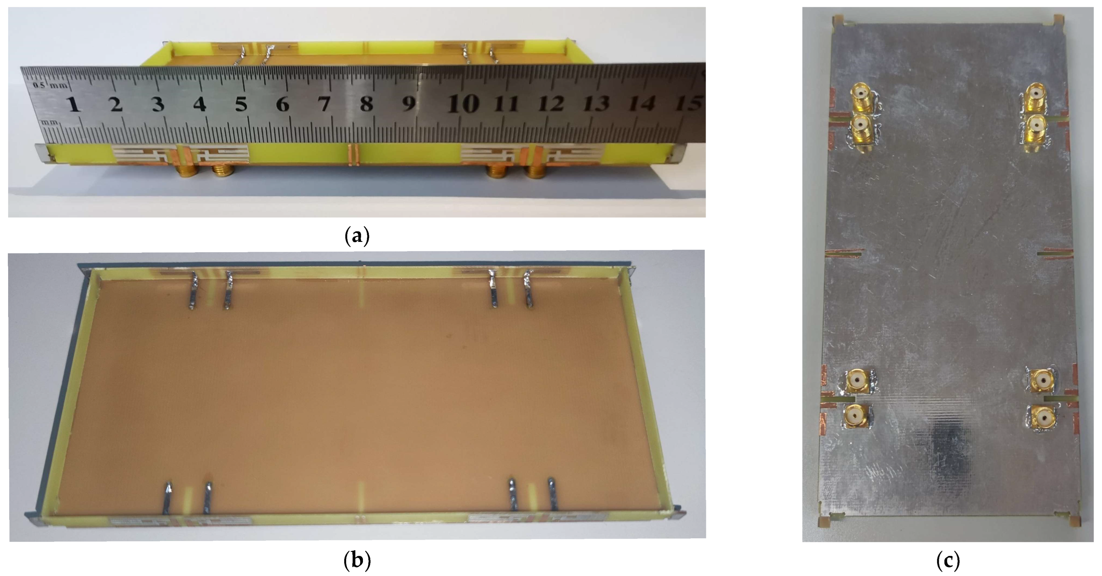
3.1. Eight-Element MIMO Antenna System Prototype
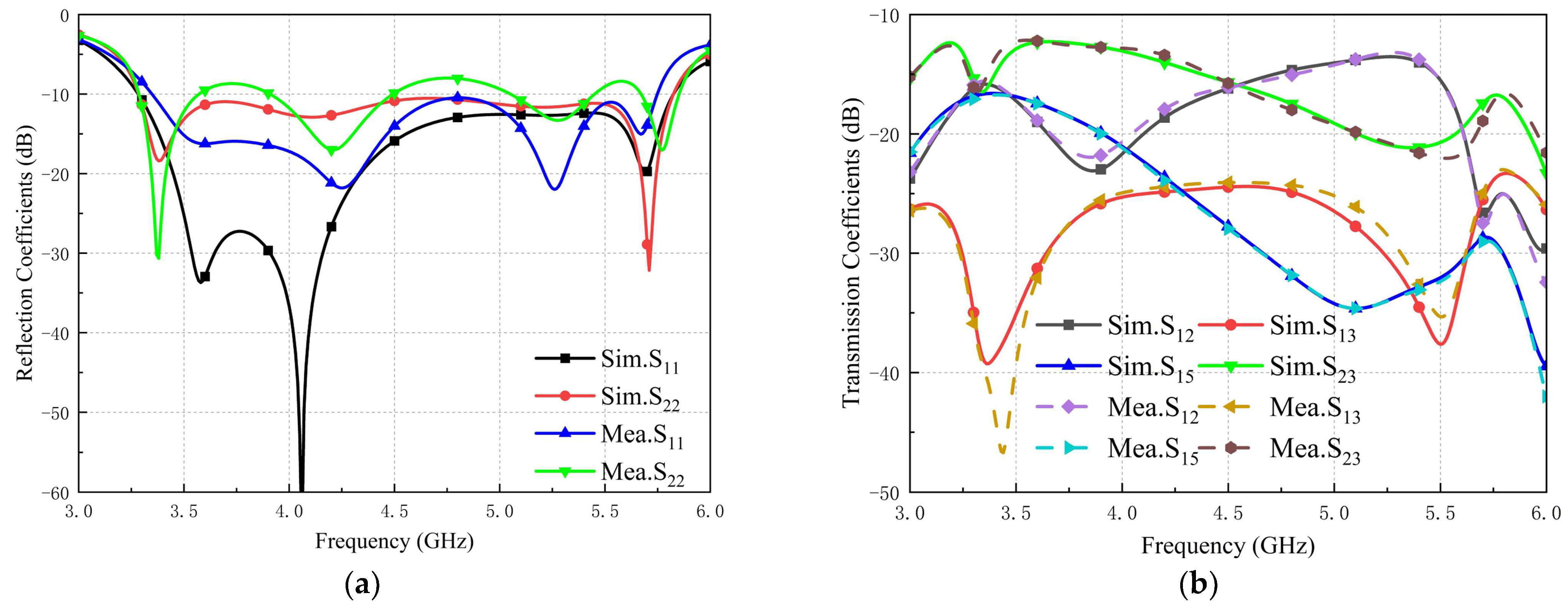
The fabricated eight-element antenna system prototype is shown in Figure 12; Figure 12a shows the side frames where the two pairs of antennas are placed; Figure 12b shows the interior of the prototype as well as the L-shaped coupled feed branch; Figure 12c shows the defective ground structure of the prototype’s metal common ground plane; and eight SMA connectors were soldered at the back ports of the prototype for testing. Similar results are no longer shown due to the symmetrical arrangement of the MIMO system.

3.1.1. S-Parameters

In Figure 13, we can see that the −10 dB operating frequency of Ant 1 and Ant 2 is 3.30~5.83 GHz, and the bandwidth length is 2530 MHz, which completely covers the N77/N78/N79 bands as well as most of the WLAN 5 GHz bands. The worst isolation occurs between Ant 2 and Ant 3 at 3.55 GHz with −12.16 dB. Due to the connection of SMA connectors and unavoidable processing and measurement errors during modeling and measurement, the test results of the fabricated prototypes differ slightly from the simulation results, but the overall trend is consistent.

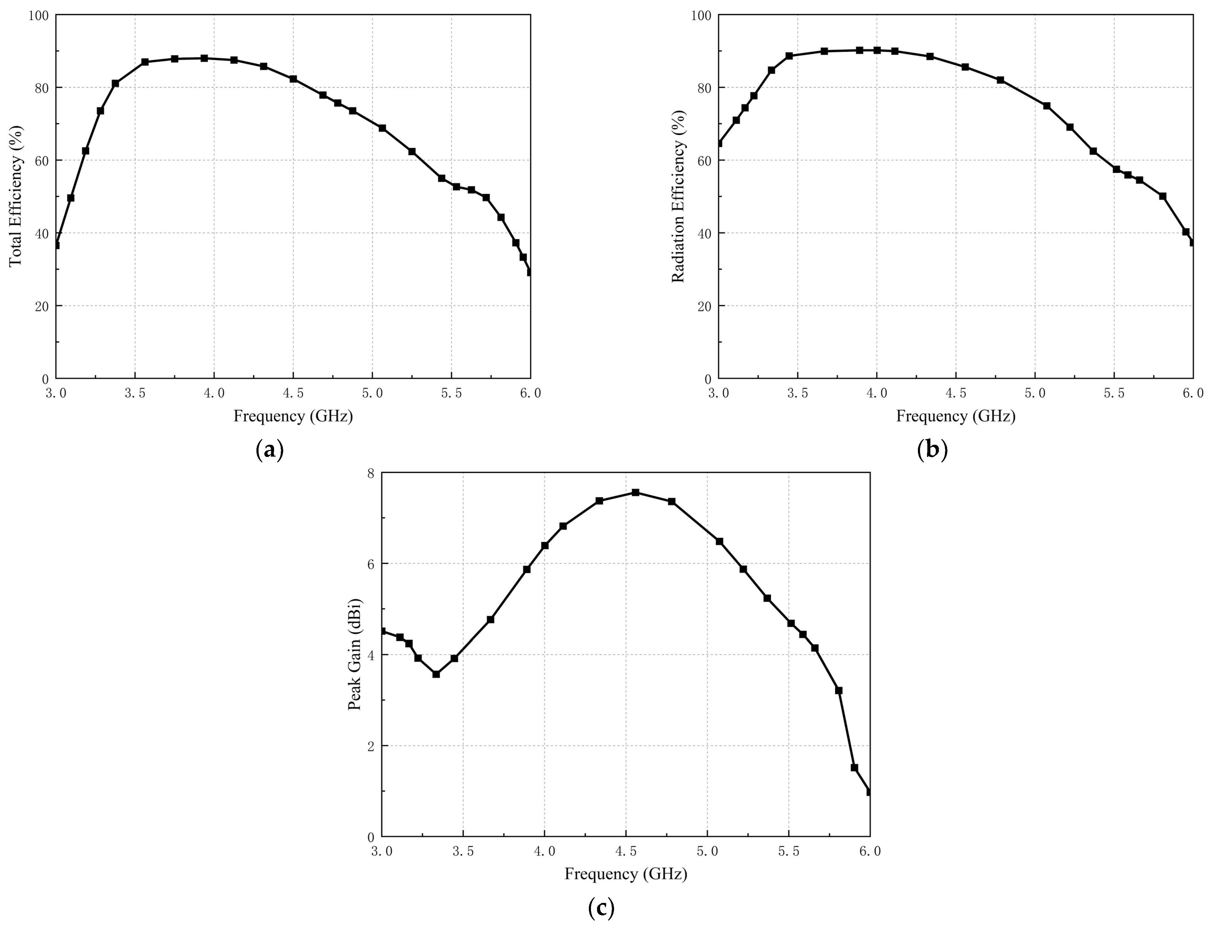
3.1.2. Total Efficiency, Radiation Efficiency, and Peak Gain
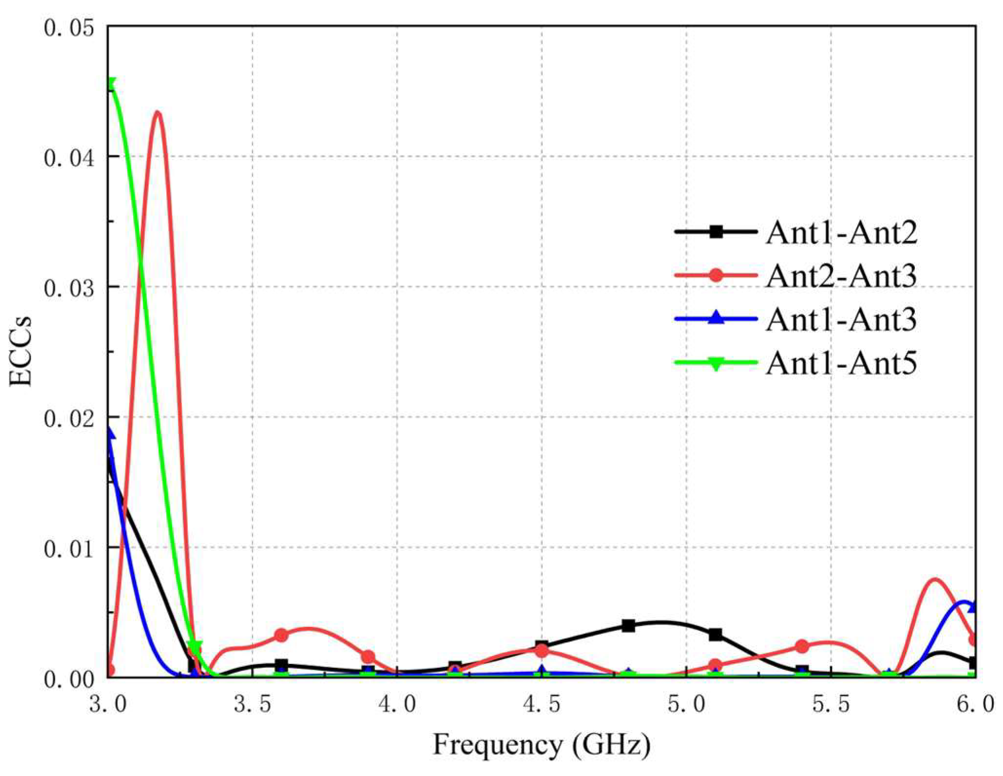
As shown in Figure 14, the antenna efficiency is mostly better than 50% and up to 88% in the N77/N78/N79 bands and the WLAN 5 GHz band. The total efficiency in the WLAN 5 GHz band is relatively low, but in the main operating frequencies we are interested in (N77/N78/N79), the antenna efficiencies are all above 60%.
As shown in Figure 14a, the total efficiency of the antenna is generally better than 50% and up to 88% in the N77/N78/N79 bands with the WLAN 5GHz band. Figure 14b shows the radiation efficiency of the antenna. By comparing Figure 14a with Figure 14b, it is found that the effect of conductor dielectric loss on the overall performance of the antenna is not significant at the operating frequency bands of the antenna. The total efficiency of the antenna is relatively low in the WLAN 5 GHz band, but the antenna efficiencies are all better than 60% at the main operating frequencies that we are interested in (N77/N78/N79). The peak gain is shown in Figure 14c and takes values ranging from 3.6 to 7.6 dBi.

3.1.3. ECC

In order to study the antenna’s uncorrelation in radiation space, we calculated the Envelope Correlation Coefficient (ECC). ECC is a parameter used to express the degree of isolation between the communication channels of the MIMO system. The ECC can either be computed by using far-field directional maps or approximated by the S-parameter using Equation (1).
E E C ( m , n ) = | s m m * s m n + s n m * s n n | 2 { 1 ( | s m m | 2 + | s n m | 2 ) } { 1 ( | s n n | 2 + | s m n | 2 ) }
From Figure 15, we can see that the ECC between any two antenna elements is lower than 0.01 at an operating frequency of between 3.30 and 5.83 GHz, which indicates that the eight-element MIMO antenna system has good spatial independence.

3.1.4. DG

The diversity gain describes the ability to distinguish independent multipath signals on a MIMO antenna system and can be derived from (2) by ECC.
D G ( m , n ) = 10 1 E C C ( m , n ) 2
The diversity gain is correlated with the envelope correlation coefficient. In Figure 16, it can be clearly observed that the DG is higher than 9.99 dB at an operating frequency of between 3.30 and 5.83 GHz, indicating that the diversity gain performs well.

3.1.5. Radiation Pattern

Due to the mirror symmetry of the arrangement of the eight-element antenna array, we measured the 2D directional maps of Ant 1 and Ant 2 at the three resonance points of 3.5, 4.5, and 5.6 GHz, respectively. Figure 17a shows the simulated and measured xoy-plane radiation patterns, and Figure 17b shows the simulated and measured xoz-plane radiation patterns. From Figure 17, we can see that there is only a slight difference between the simulated and actual measured antenna radiation direction diagrams, which is caused by manufacturing and testing errors. From Figure 17a,b, we can clearly observe that, thanks to the symmetric structure of the antenna pairs, the maximum radiation directions of Ant 1 and Ant 2 are well complementary thanks to the symmetric structure of the antenna pairs. That ensures that the proposed eight-element MIMO antenna system has good omnidirectionality and spatial independence, and the overall performance of MIMO antenna arrays is good and suitable for the application of 5G mobile terminals.

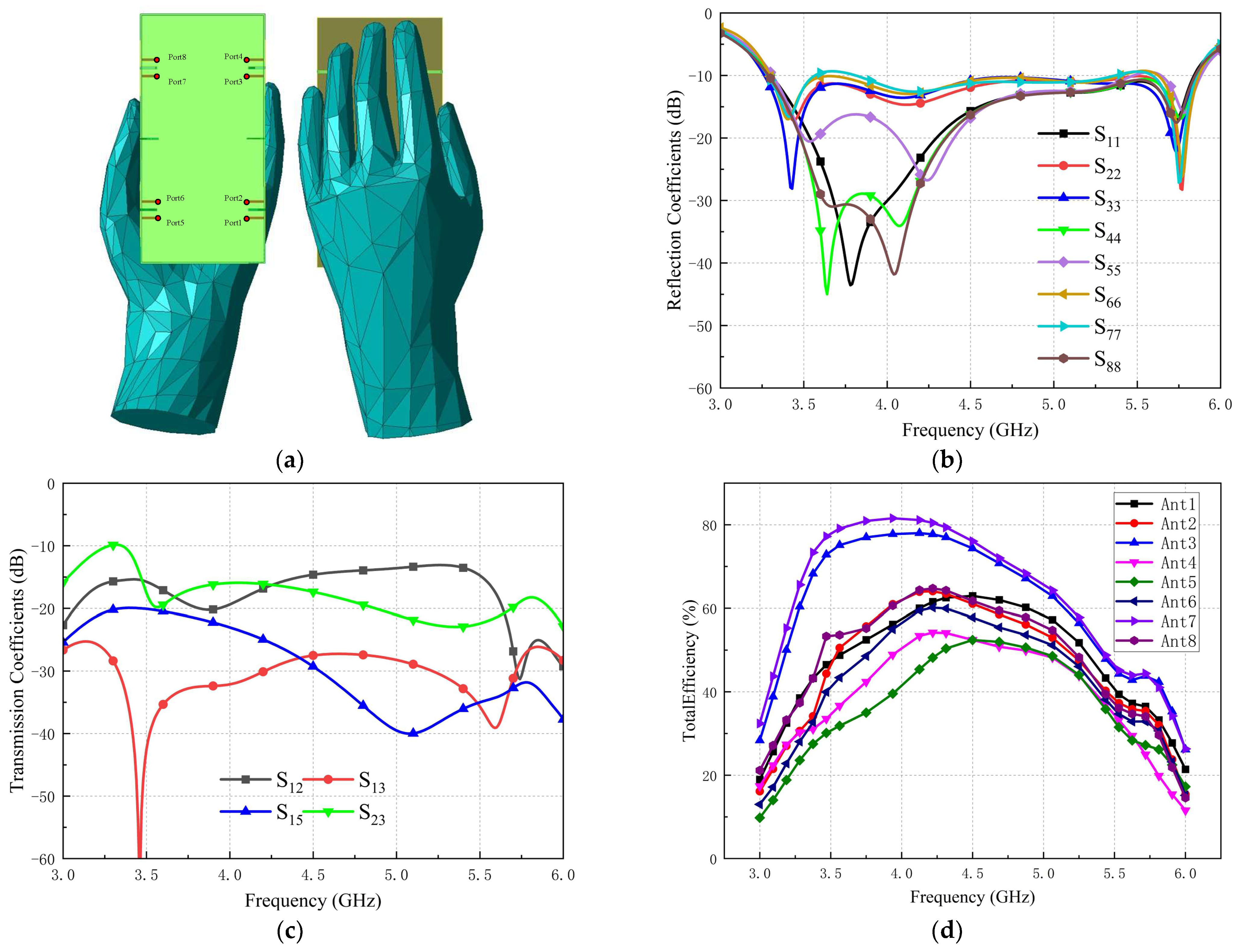
3.2. Handheld Effects

We simulate the effect of the user’s hand on the antenna performance of an MIMO cell phone when making a phone call or browsing for information, and verify the robustness of the MIMO antenna system. The poses of the simulated handheld antenna model are shown in Figure 18a, with antennas 1, 2, 5, and 6 close to the palm and antennas 3, 4, 7, and 8 close to the fingers. In Figure 18b, we can clearly observe that the reflection coefficient of Ant 7 is slightly larger than −10 dB at 3.6 GHz and 5.5 GHz, and slightly more than −10 dB at 5.6 GHz for Ant 5. This is due to the fact that the human body tissues themselves belong to a kind of conductive material. The thumb portion of the hand model is relatively close to the Ant 5 and Ant 7, which absorbs and scatters the electromagnetic waves radiated by Ant 5 and Ant 7 and scattering. Overall, the reflection coefficients of antennas 1–8 are weakly affected in the frequency band from 3.30 to 5.83 GHz.
Figure 18c shows that the isolation between Ant 2 and Ant 3 becomes weaker at 3.3 GHz to −10 dB. It is caused by the fact that Ant 2 and Ant 3 are closer to the small thumb of the hand model, so part of the signal is coupled into the human body. Overall, the isolation of each antenna unit is good at the operating frequency. Figure 18d shows the variation of the total efficiency of each antenna unit after adding the human hand model. The influence of the human hand model leads to a slight decrease in the total efficiency, ranging from 30% to 82%. In summary, the constructed MIMO antenna system is less affected by the influence of the human hand model, and the overall performance meets the requirements of 5G mobile terminals.
Table 1 compares the eight-element MIMO antenna array proposed in this paper with some similar antenna arrays proposed recently. The comparison reveals that most of the design proposals have problems such as larger antenna size or narrower coverage bandwidth. The composite decoupling structure proposed in this paper has significant improvement on the mutual coupling between two antenna pairs, and the design scheme provides a good balance between antenna performance and size.

4. Conclusions

In this paper, an antenna pair with a coupled feed structure and a defected ground structure is proposed by the CMA method, which is characterized by wide bandwidth, high isolation and compact structure. Simulation results show that the proposed MIMO antenna pair has an impedance bandwidth of 3.28–5.85 GHz (−10 dB) with an isolation of lower than −16.7 dB, and the antenna pair’s radiating direction graphs can be spatially complementary to each other, which makes the antenna pair have good omnidirectionality. The proposed antenna pair is utilized to construct an eight-element MIMO antenna system, and the composite decoupling technique is applied to decouple the two antenna pairs. The constructed eight-element MIMO antenna system is simulated, a prototype is fabricated for measurements, and the results show that the MIMO antenna system has a −10 dB impedance bandwidth of 3.30–5.83 GHz, isolation lower than −12.42 dB, ECC lower than 0.01, the total efficiency is generally better than 50%, and the maximum is up to 88%. Finally, the effect of the human hand on the performance of the antenna system when the user is using the cell phone is simulated, which further validates the robustness of the proposed MIMO antenna system with its potential to be applied to future 5G mobile terminals.

Author Contributions

Conceptualization, Z.L. and Y.W.; methodology, Z.L. and Y.H.; software, Z.L. and L.Z.; validation, Z.L and Y.W.; formal analysis, Z.L. and Y.H.; writing—review and editing, Z.L.; supervision, Y.W.; project administration, Z.L.; funding acquisition, Y.W. All authors have read and agreed to the published version of the manuscript.

Funding

This research was funded by National Natural Science Foundation of China (Grant No. 61366006). This research was funded by Gansu Provincial Department of Education: Outstanding Graduate Students “Innovation Star” Project, grant number 2023CXZX-545.

Institutional Review Board Statement

Not applicable.

Informed Consent Statement

Not applicable.

Data Availability Statement

Not applicable.

Conflicts of Interest

The authors declare no conflict of interest. The funders had no role in the design of the study; in the collection, analyses, or interpretation of data; in the writing of the manuscript; or in the decision to publish the results.

References

  1. Dilli, R. Analysis of 5G wireless systems in FR1 and FR2 frequency bands. In Proceedings of the 2020 2nd International Conference on Innovative Mechanisms for Industry Applications (ICIMIA), Bangalore, India, 5–7 March 2020; pp. 767–772. [Google Scholar]
  2. Sun, L.; Feng, H.; Li, Y.; Zhang, Z. Compact 5G MIMO mobile phone antennas with tightly arranged orthogonal-mode pairs. IEEE Trans. Antennas Propag. 2018, 66, 6364–6369. [Google Scholar] [CrossRef]
  3. Alibakhshikenari, M.; Babaeian, F.; Virdee, B.S.; Aïssa, S.; Azpilicueta, L.; See, C.H.; Althuwayb, A.A.; Huynen, I.; Abd-Alhameed, R.A.; Falcone, F. A comprehensive survey on “Various decoupling mechanisms with focus on metamaterial and metasurface principles applicable to SAR and MIMO antenna systems”. IEEE Access 2020, 8, 192965–193004. [Google Scholar] [CrossRef]
  4. Mak, A.C.; Rowell, C.R.; Murch, R.D. Isolation enhancement between two closely packed antennas. IEEE Trans. Antennas Propag. 2008, 56, 3411–3419. [Google Scholar] [CrossRef]
  5. Li, Z.; Du, Z.; Takahashi, M.; Saito, K.; Ito, K. Reducing mutual coupling of MIMO antennas with parasitic elements for mobile terminals. IEEE Trans. Antennas Propag. 2011, 60, 473–481. [Google Scholar] [CrossRef]
  6. Tran, H.H.; Nguyen-Trong, N. Performance enhancement of MIMO patch antenna using parasitic elements. IEEE Access 2021, 9, 30011–30016. [Google Scholar] [CrossRef]
  7. Chiu, C.-Y.; Cheng, C.-H.; Murch, R.D.; Rowell, C.R. Reduction of mutual coupling between closely-packed antenna elements. IEEE Trans. Antennas Propag. 2007, 55, 1732–1738. [Google Scholar] [CrossRef]
  8. Zhao, X.; Riaz, S. A dual-band frequency reconfigurable MIMO patch-slot antenna based on reconfigurable microstrip feedline. IEEE Access 2018, 6, 41450–41457. [Google Scholar] [CrossRef]
  9. Jamal, M.Y.; Li, M.; Yeung, K.L. Isolation enhancement of closely packed dual circularly polarized MIMO antenna using hybrid technique. IEEE Access 2020, 8, 11241–11247. [Google Scholar] [CrossRef]
  10. Wang, Y.; Du, Z. A wideband printed dual-antenna with three neutralization lines for mobile terminals. IEEE Trans. Antennas Propag. 2013, 62, 1495–1500. [Google Scholar] [CrossRef]
  11. Zhang, S.; Pedersen, G.F. Mutual coupling reduction for UWB MIMO antennas with a wideband neutralization line. IEEE Antennas Wirel. Propag. Lett. 2015, 15, 166–169. [Google Scholar] [CrossRef]
  12. Liu, R.; An, X.; Zheng, H.; Wang, M.; Gao, Z.; Li, E. Neutralization line decoupling tri-band multiple-input multiple-output antenna design. IEEE Access 2020, 8, 27018–27026. [Google Scholar] [CrossRef]
  13. Sarrazin, J.; Mahé, Y.; Avrillon, S.; Toutain, S. Investigation on cavity/slot antennas for diversity and MIMO systems: The example of a three-port antenna. IEEE Antennas Wirel. Propag. Lett. 2008, 7, 414–417. [Google Scholar] [CrossRef]
  14. Kiani, S.H.; Savci, H.S.; Abubakar, H.S.; Parchin, N.O.; Rimli, H.; Hakim, B. Eight Element MIMO Antenna Array With Tri-Band Response for Modern Smartphones. IEEE Access 2023, 11, 44244–44253. [Google Scholar] [CrossRef]
  15. Chang, L.; Yu, Y.; Wei, K.; Wang, H. Polarization-orthogonal co-frequency dual antenna pair suitable for 5G MIMO smartphone with metallic bezels. IEEE Trans. Antennas Propag. 2019, 67, 5212–5220. [Google Scholar] [CrossRef]
  16. Wong, K.L.; Chang, H.J.; Li, W.Y. Integrated triple-wideband triple-inverted-F antenna covering 617–960/1710–2690/3300–4200 MHz for 4G/5G communications in the smartphone. Microw. Opt. Technol. Lett. 2018, 60, 2091–2096. [Google Scholar] [CrossRef]
  17. Sui, J.; Wu, K.-L. Quad-IFA MIMO Antennas Using Self-curing Decoupling Technique. In Proceedings of the 2018 IEEE International Symposium on Antennas and Propagation & USNC/URSI National Radio Science Meeting, Boston, MA, USA, 8–13 July 2018; pp. 1383–1384. [Google Scholar]
  18. Sui, J.; Dou, Y.; Mei, X.; Wu, K.-L. Self-curing decoupling technique for MIMO antenna arrays in mobile terminals. IEEE Trans. Antennas Propag. 2019, 68, 838–849. [Google Scholar] [CrossRef]
  19. Chen, S.-C.; Wang, Y.-S.; Chung, S.-J. A decoupling technique for increasing the port isolation between two strongly coupled antennas. IEEE Trans. Antennas Propag. 2008, 56, 3650–3658. [Google Scholar] [CrossRef]
  20. Sun, L.; Li, Y.; Zhang, Z.; Feng, Z. Wideband 5G MIMO antenna with integrated orthogonal-mode dual-antenna pairs for metal-rimmed smartphones. IEEE Trans. Antennas Propag. 2019, 68, 2494–2503. [Google Scholar] [CrossRef]
  21. Liu, H.-Y.; Huang, C.-J. Wideband MIMO antenna array design for future mobile devices operating in the 5G NR frequency bands n77/n78/n79 and LTE band 46. IEEE Antennas Wirel. Propag. Lett. 2019, 19, 74–78. [Google Scholar]
  22. Serghiou, D.; Khalily, M.; Singh, V.; Araghi, A.; Tafazolli, R. Sub-6 GHz dual-band 8 × 8 MIMO antenna for 5G smartphones. IEEE Antennas Wirel. Propag. Lett. 2020, 19, 1546–1550. [Google Scholar] [CrossRef]
  23. Yu, Z.; Wang, M.; Xie, Y. An improved loop ultra-wideband mimo antenna system for 5G mobile terminals. Prog. Electromagn. Res. Lett. 2020, 93, 99–106. [Google Scholar] [CrossRef]
  24. Yuan, X.-T.; He, W.; Hong, K.-D.; Han, C.-Z.; Chen, Z.; Yuan, T. Ultra-wideband MIMO antenna system with high element-isolation for 5G smartphone application. IEEE Access 2020, 8, 56281–56289. [Google Scholar] [CrossRef]
  25. Sun, L.; Li, Y.; Zhang, Z. Wideband integrated quad-element MIMO antennas based on complementary antenna pairs for 5G smartphones. IEEE Trans. Antennas Propag. 2021, 69, 4466–4474. [Google Scholar] [CrossRef]
  26. Yuan, X.-T.; Chen, Z.; Gu, T.; Yuan, T. A wideband PIFA-pair-based MIMO antenna for 5G smartphones. IEEE Antennas Wirel. Propag. Lett. 2021, 20, 371–375. [Google Scholar] [CrossRef]
  27. Hei, Y.Q.; He, J.G.; Li, W.T. Wideband decoupled 8-element MIMO antenna for 5G mobile terminal applications. IEEE Antennas Wirel. Propag. Lett. 2021, 20, 1448–1452. [Google Scholar] [CrossRef]
  28. Sun, L.; Li, Y.; Zhang, Z. Wideband decoupling of integrated slot antenna pairs for 5G smartphones. IEEE Trans. Antennas Propag. 2020, 69, 2386–2391. [Google Scholar] [CrossRef]
  29. Du, K.; Wang, Y.; Zhang, L.; Hu, Y. Design of Wideband Decoupling Antenna Pairs for 5G Portable Devices at N77/N78/N79 Bands. Micromachines 2022, 13, 1964. [Google Scholar] [CrossRef]
  30. Ren, A.; Yu, H.; Yang, L.; Huang, Z.; Zhang, Z.; Liu, Y. A Broadband MIMO Antenna Based on Multi-Modes for 5G Smartphone Applications. IEEE Antennas Wirel. Propag. Lett. 2023, 22, 1642–1646. [Google Scholar] [CrossRef]
  31. Desai, A.; Palandoken, M.; Kulkarni, J.; Byun, G.; Nguyen, T.K. Wideband flexible/transparent connected-ground MIMO antennas for sub-6 GHz 5G and WLAN applications. IEEE Access 2021, 9, 147003–147015. [Google Scholar] [CrossRef]
  32. Singh, H.; Sohi, B.S.; Gupta, A. Designing and performance evaluation of metamaterial inspired antenna for 4G and 5G applications. Int. J. Electron. 2021, 108, 1035–1057. [Google Scholar] [CrossRef]
Figure 1. Antenna system structure diagram.
Applsci 13 09370 g001
Figure 2. Evolution of antenna pairs.
Applsci 13 09370 g002
Figure 3. Evolution of S-parameters. (a) S11. (b) S12.
Applsci 13 09370 g003
Figure 4. CMA of Case 1. (a) MS. (b) MWC. (c) Characteristic current distributions.
Applsci 13 09370 g004
Figure 5. CMA of Case 2. (a) MS. (b) MWC. (c) Characteristic current distributions.
Applsci 13 09370 g005
Figure 6. CMA of Case 3. (a) MS. (b) MWC.
Applsci 13 09370 g006
Figure 7. Electric current distribution. (a) Case 3. (b) Case 4.
Applsci 13 09370 g007
Figure 8. Simulated S-parameters with different decoupled structure.
Applsci 13 09370 g008
Figure 9. Variable parameters.
Applsci 13 09370 g009
Figure 10. Effect of different Ld and Wd values on Sparameters. (a) Ld. (b) Wd.
Applsci 13 09370 g010
Figure 11. Effect of different Wc values on S-parameters.
Applsci 13 09370 g011
Figure 12. (a) Side borders of the prototype. (b) The interior of the prototype. (c) The back of the prototype.
Applsci 13 09370 g012
Figure 13. (a) Simulated and measured reflection coefficients. (b) Simulated and measured trans-mission coefficients.
Applsci 13 09370 g013
Figure 14. (a)Total efficiency. (b) Radiation efficiency. (c) Peak gain.
Applsci 13 09370 g014
Figure 15. Calculated ECC.
Applsci 13 09370 g015
Figure 16. Calculated DG.
Applsci 13 09370 g016
Figure 17. Simulated and measured radiation direction plots of ant1 and ant2 at 3.5, 4.5, and 5.6 GHz. (a) xoy plane. (b) xoz plane.
Applsci 13 09370 g017
Figure 18. (a) Model of a user holding a cell phone in the left hand. (b) Simulated reflection coefficients. (c) Simulated transmission coefficients. (d) Simulated total efficiency.
Applsci 13 09370 g018
Table 1. Comparison with other 5G terminal MIMO antennas.
DesignAntenna
Pairs
Decoupling
Methods
Element Size
(mm2)
Frequency
(GHz)
Isolation
(dB)
Total
Efficiency (%)
ECC
[20]Orthogonal mode40 × 7.53.3~5.0 GHz
(−6 dB)
<−1231.6–76.7<0.11
[22]Neutralization lines35.7 × 53.1~3.85 GHz
4.8~6 GHz
(−10 dB)
<−1760–71<0.06
[23]-Neutralization lines17.5 × 7.53.3–5.6 GHz
(−6 dB)
<−1545–80<0.03
[27]Parasitic elements and DGS37 × 63.3–5.95 GHz
(−6 dB)
<−1547–78<0.11
[29]DGS28 × 63.23–5.24
(−10 dB)
<−1150–89<0.04
[30]-DGS22 × 23.3–6 GHz
(−6 dB)
<−12.150–61<0.2
ProposedParasitic elements and DGS33.6 × 63.28–5.85 GHz
(−10 dB)
<−12.4250–88<0.01
Disclaimer/Publisher’s Note: The statements, opinions and data contained in all publications are solely those of the individual author(s) and contributor(s) and not of MDPI and/or the editor(s). MDPI and/or the editor(s) disclaim responsibility for any injury to people or property resulting from any ideas, methods, instructions or products referred to in the content.

