1. Introduction
The dry scroll vacuum pump is a kind of simple structure, small size, low vibration, quiet, and reliable positive displacement vacuum pump. The water-cooled horizontal dry scroll vacuum pump was originally developed by Kushiro in 1990 [
1]. In 1998, Su et al. [
2] and Sawada et al. [
3,
4] developed an air-cooled dry scroll vacuum pump. They established the model of lean gas flow leakage through the scroll clearance and also calculated the pumping performance. Their experiments show that the results coincided well with the calculation. To predict the scroll machine performance through theoretical simulation, some mathematical models were established by researchers. Chen et al. [
5] developed a three-dimensional mathematical model to simulate the flow condition in a scroll. Cui [
6] accomplished the numerical simulation of the operating process of the entire scroll compressor and provided the detailed physics of the unsteady flows inside the scroll compressors. Qiang [
7] set up the general geometrical model of a scroll compression chamber which could demonstrate the deforming, opening, and vanishing process of all scroll chambers. Winandy et al. [
8], Chen et al. [
9,
10], Cuevas and Lebrun [
11], and Wang et al. [
12,
13] developed different mathematical models to predict compressor performance. Youn and Cho [
14,
15], and Li et al. [
16] used experimental research methods to study the flow characteristics in scroll compressors. Computational fluid dynamics (CFD) has also been applied to study the inner flow of scroll compressors and scroll expanders [
17,
18,
19,
20,
21,
22,
23,
24,
25]. Sun et al. [
21] Zhang et al. [
22], and Zheng et al. [
25] all used the structured dynamic mesh method to achieve the motion of the scroll chambers. Compared with the structured dynamic mesh method, the spring smoothing method only needs one mesh file, and the mesh movement can be realized by controlling the coordinates of grids. The spring smoothing method is very efficient for calculation and can control the changes in overall nodes through the formulations of motion.
In recent years, Li et al. [
26,
27] analyzed the working process of the scroll pump, introduced the factors that can affect the performance such as the rotational speed and heat transfer, and improved the related pumping theory by combining experiments. In general, considering the special structure and operating condition of the scroll vacuum pump, it is difficult to obtain the internal flow characteristics. Experimental research is not the primary method to study the flow characteristics of the scroll vacuum pump. Our previous work once used the CFD method to numerically simulate the dry scroll vacuum pump [
28] and analyzed the working process of “under-compression”, “over-compression”, and other phenomena. The author also simulated another dry scroll vacuum pump which has a more complicated structure and working process [
29], compared the pumping speed at different suction pressure, and analyzed the working process of the scroll pump.
With extensive application in chemical, pharmaceutical, semiconductor, and scientific instruments, dry scroll vacuum pumps will face more complex and demanding pumping conditions, and the requirements for the performance of the dry scroll vacuum pump are more stringent. As a kind of variable capacity dry vacuum pump, the dry scroll vacuum pump compresses the pumped gas to generate a large amount of heat during operation, which causes the temperature of the pump body to rise sharply, thereby affecting the working performance of the pump. When the component temperature rises seriously, the pump may get stuck or even be damaged. A theoretical model of the heat transfer rate between rarefied gas and the working chamber wall was developed by Li et al. [
26]. This performance prediction model of the dry scroll vacuum pump considered the heat transfer between the gas and the working chamber wall. However, the detailed flow field and the impact of the structural movement on unsteady flow cannot be accurately predicted by the dimensionless mathematical models. Therefore, further analyzing the thermodynamic characteristics of the dry scroll vacuum pump by CFD method and studying the impact of operating temperature on performance are very necessary for the design and application of the cooling system of the dry scroll vacuum pump.
In recent years, the world’s energy supply has become increasingly tight, and the energy crisis continues to deepen. Under the influence of extreme weather and other factors, the supply and demand of electricity have become tenser. In order to respond to global climate change, industrial equipment should pay more attention to improving energy efficiency. There is no acknowledged method for assessing the energy efficiency of the dry scroll vacuum pump. Considering the development of energy saving, the energy efficiency assessment system of the scroll pump needs to be defined. This study proposes a way to evaluate the energy efficiency of the dry scroll vacuum pump and introduces the energy efficiency ratio (EER) into the assessment system of scroll vacuum pump performance.
As further in-depth research of our previous work, based on the spring smoothing method, the numerical simulation model of the multi-stage dry scroll vacuum pump is established. Under the suction pressure of 1000 Pa, the simulation calculation is carried out at different operating temperatures of fixed scrolls (25 °C, 45 °C, and 65 °C). Moreover, the pumping speed and gas compression power are analyzed. The energy efficiency ratio of the dry scroll vacuum pump is evaluated. This work provides a valuable reference for the design and optimization of the dry scroll vacuum pump.
2. Numerical Model
2.1. Geometry of Dry Scroll Vacuum Pump
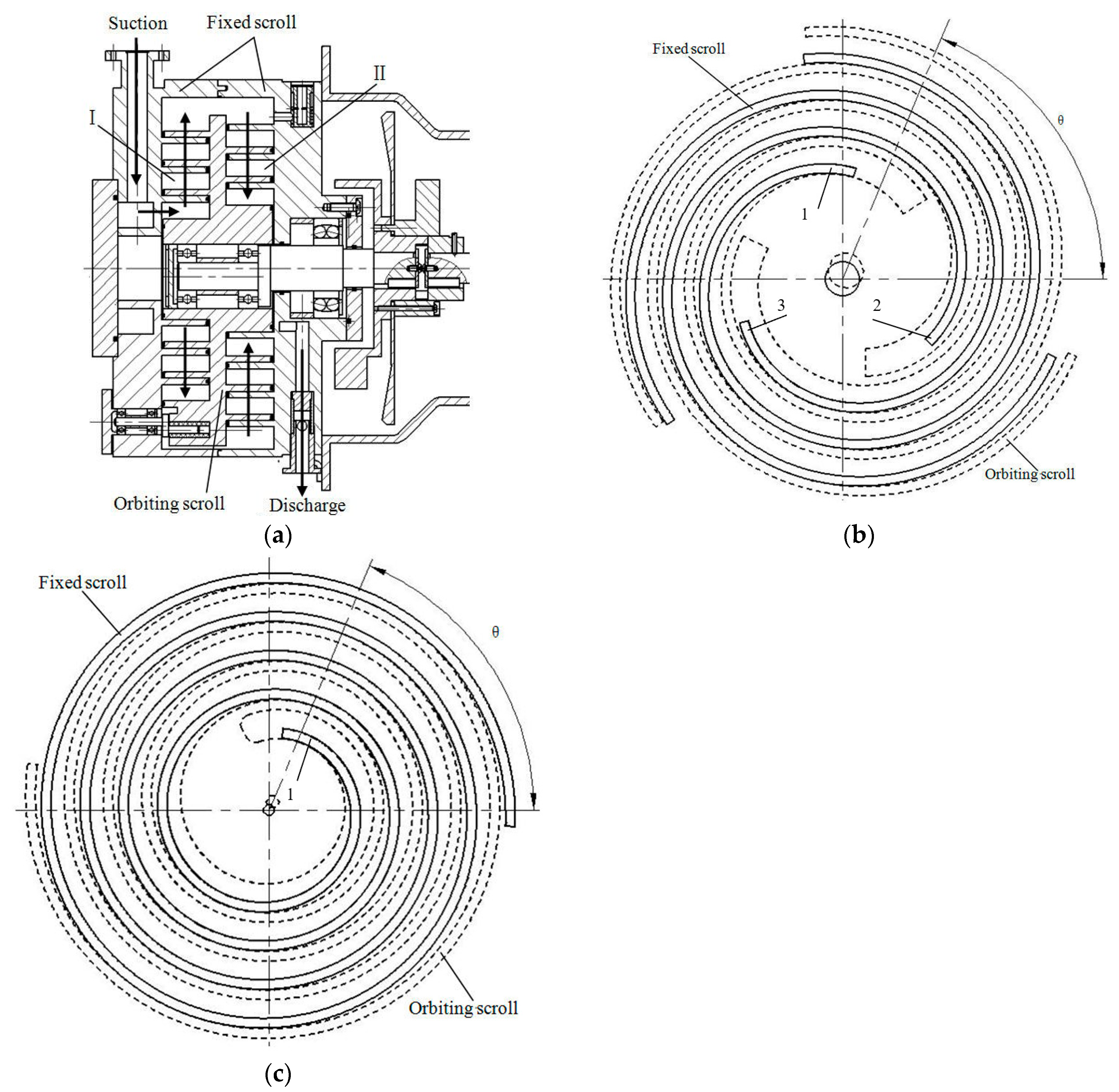
The gas is compressed in a working chamber enclosed by the fixed scroll and the orbiting scroll. A certain type (Agilent TriScroll 300, Lexington, MN, USA) of multi-stage scroll vacuum pump is taken as the research object, and its structure is shown in
Figure 1. There are two fixed scrolls, each corresponding to a different direction, and an orbiting scroll is positioned between the two fixed scrolls. Two working chambers are formed on each side of the orbiting scroll.
During the working process, the gas is pumped through the inlet and is compressed in the first stage of the pump chamber. Then, it passes through the circumferential channel of the orbiting scrolls and enters the second stage of the pump chamber, where it is further compressed. Finally, the compressed gas is discharged through the exhaust.
The profiles of scroll warps are involutes of the circle, there are three scroll wraps in the first-stage pump chamber, and there is only one scroll wrap in the second-stage pump chamber, as shown in
Figure 1b,c.
Due to the complex structure of the dry scroll vacuum pump, the flow area is reasonably simplified while ensuring calculation accuracy. Only the axial clearance is ignored, because there are sealing measures for it and the leakage is very small. The radial clearance is kept, and its value is 0.05 mm. After simplifying, the flow region model of the multi-stage dry scroll vacuum pump is established, as shown in
Figure 2. The main structural parameters are given in
Table 1.
2.2. Governing Equations
As the shape and volume of the working chamber are constantly changing, the gas compression process is an unsteady compressible flow. In the Cartesian coordinate system, the governing equation with an unsteady compressible flow [
30,
31,
32] can be expressed as Equation (1):
where
ρ is the fluid density,
U is the velocity of the fluid,
W is the velocity of the boundary of the control volume,
μeff is the viscosity coefficient containing turbulent viscosity,
Γeff is diffusion coefficient containing turbulent diffusion,
φ is a scalar, such as medium per unit mass enthalpy or internal energy,
SU,
Sφ are source terms,
dn is the outer normal vector of the surface,
i,
j represents the axis in the Cartesian coordinate system.
Dynamic mesh techniques can be applied to the simulation of computational domain changes caused by boundary deformation or motion [
33]. When the dry scroll vacuum pump works, the shape and volume of the working chamber constantly change. Therefore, the actual working condition is simulated by the dynamic mesh method.
As the theorem of geometric conservation law must be satisfied in the dynamic mesh method, the time derivative of the control volume [
33,
34,
35] can be calculated by:
The renormalization group (RNG)
k-ε model is based on the renormalization group analysis of the Navier–Stokes equations. This model represents the effects of small-scale turbulence by means of a random forcing function in the Navier-Stokes equation [
30]. The transport equations for turbulence generation and dissipation are the same as those for the standard
k-ε model, but the model constants are different.
The transport equations for turbulence kinetic energy
k and turbulence dissipation rate
ε become [
36]:
where
Cε2,
σk, and
σε are constants,
Cε2 = 1.68,
σk = 0.7179 and
σε = 0.7179. The formula of
Cε1 is given by:
and
Pk is the turbulence production due to viscous forces, which is:
where
μt is the turbulence viscosity,
where
Cμ is constant,
Cμ = 0.085.
2.3. Mesh Movement Method and Computational Mesh
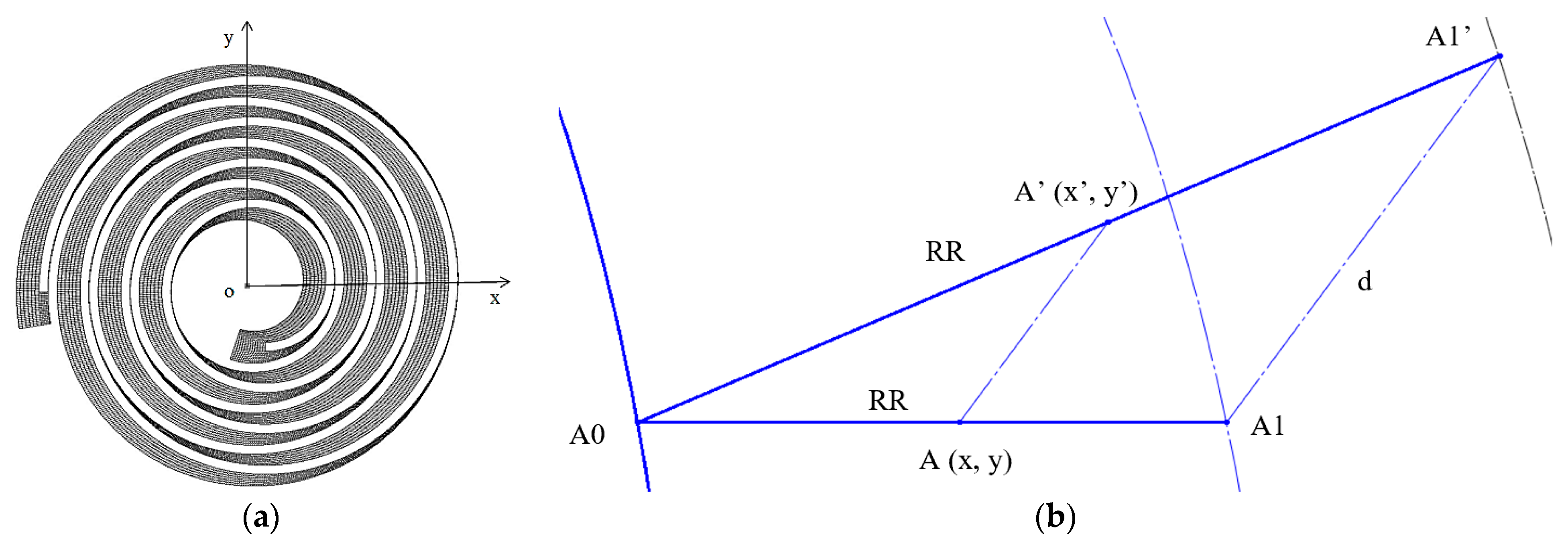
Both working chambers have huge deformation, and using general dynamic mesh models will stop the calculation process due to grid distortions or the negative volume of grids. Therefore, a spring smoothing method based on hexahedral mesh is adopted in order to ensure the quality of the mesh and to facilitate the updating of the grid nodes. At the same time, the grid was always aligned in a certain direction.
When the mesh moves, the coordinates of the Z direction of the mesh node are constant, and the X and Y directions of the node are changed to the specified position according to the calculation and control of the program. Point A is a point in the flow domain, and point A0 will be found at the fixed scroll, and point A1 will be found at the orbiting scroll. A proportional coefficient RR can be calculated by the distance ratio (l
AA0/l
A0A1). The displacement of point A1 is d, maintaining the original coefficient RR, and the new coordinate A’ (x’, y’) of the grid node can be calculated, as shown in
Figure 3.
Figure 4 shows the mesh of planes parallel to the XY coordinate plane when the orbiting scroll is at different angles.
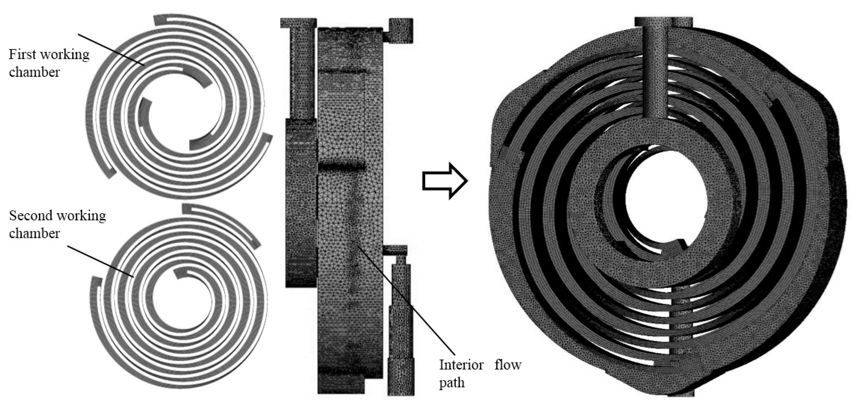
The interior flow area of the multi-stage scroll vacuum pump is complicated. Since the axial clearance of the pump is generally sealed by chip seal, the axial clearance is ignored, and the radial clearance is considered in this paper. As shown in
Figure 5, the flow area in the pump is divided into the first-stage working chamber, second-stage working chamber, and interior flow path. These geometrical areas use separate mesh.
When the model is established, the above geometric areas are combined into an overall model by two interfaces for numerical calculation. In the working chamber, in order to operate and control the mesh moving, the hexahedral mesh is used, and the interior flow path area uses the tetrahedral mesh.
2.4. Numerical Simulation
The commercial software is used to simulate the unsteady compressible flow inside the multi-stage dry scroll vacuum pump. The boundary conditions are set, and the parameters of the model are controlled according to the operating and experimental conditions.
The discharges of the model are set as pressure boundaries and kept at 101,325 Pa (1 atmospheric pressure).
The Knudsen number (
Kn) [
37] is a dimensionless number that allows for characterizing the gas flow regimes. It is defined as:
where
λ is the mean free path,
d is a characteristic dimension of the system. Based on our previous work [
29], the maximum Knudsen number in the flow field is calculated to be 0.133 when the suction pressure is 1 kPa. In fact, the transitional flow begins to appear at the radial clearance (0.05 mm) closing to the suction. Considering that, the flow field with a large Knudsen number is limited to the small local space proximity to the suction part, while in other areas, there is significant viscous flow, even turbulent flow. Therefore, it is appropriate to set the pressure boundary of the suction port to 1 kPa.
The wall boundaries are set as no-slip smooth walls. According to the experience, the temperature on the surface of the scroll pump casing could reach 313.15 K–323.15 K in general while it operates, and a temperature gradient exists in the pump body. Therefore, the wall temperature of the actual situation is set at 338.15 K (65 °C).
As shown in
Figure 1a, the fixed scroll and orbiting scroll of the scroll vacuum pump have different heat dissipation structures. The fixed scroll can be cooled directly by the fan, while the orbiting scroll cannot. Thus, changing the heat dissipation capacity of the scroll pump, the temperature of the fixed scroll has a large change, and the temperature of orbiting scroll changes little. Therefore, in the numerical model, when the heat dissipation capacity is improved (e.g., changing fan airflow), the wall temperature of the fixed scroll will change, and the wall temperature of the orbiting scroll will remain the same. To analyze the effect of operating temperature on performance in the dry scroll vacuum pump, two other sets of wall temperature conditions are selected to simulate different heat dissipation capacities, as shown in
Table 2.
The rotating speed is taken at 1425 rpm (50 Hz), and the time step is equal to the time orbiting scroll rotate turns 1°.
The gas is controlled by the governing equation and the gas state equation. The gas is ideal air.
Spatial discretization and time discretization adopt a hybrid format and implicit second-order accuracy format, respectively. The turbulence model is the RNG k-ε two-equation model. The residual in the calculation is controlled to less than 10−4. During the calculation, the pumping speed, the torque of the orbiting scroll caused by gas compression, and the pressure of two points (P1 and P2) are monitored.
2.5. Grid Independence and Time Step Size Independence
The accuracy of numerical simulation is affected by factors such as grid quality, grid number, and time step size [
38,
39]. For transient numerical simulation, it is necessary to verify that the number of grids and the time step size used in the simulation are not correlated with the calculation results.
The independence test of mesh density is conducted to examine the reliability and accuracy of the mesh. Mesh refinement uses the local refinement technique so that an increase in computational accuracy is achieved with a small change in the number of nodes. The results of grid independence analysis are listed in
Table 3.
Considering the simulation efficiency and numerical accuracy, it is more appropriate to select mesh 2 to do this analysis. The number of grid nodes of each flow field is listed in
Table 4.
As shown in
Table 5, two sets of time steps are selected to study. With rotating speed taken at 1425 rpm (50 Hz), time step 1 is equal to the time orbiting scroll rotate turns 1°, and time step 2 is equal to the time orbiting scroll rotate turns 0.5°.
Based on time step size independence analysis, it is more appropriate to select time step 1 to do this analysis.
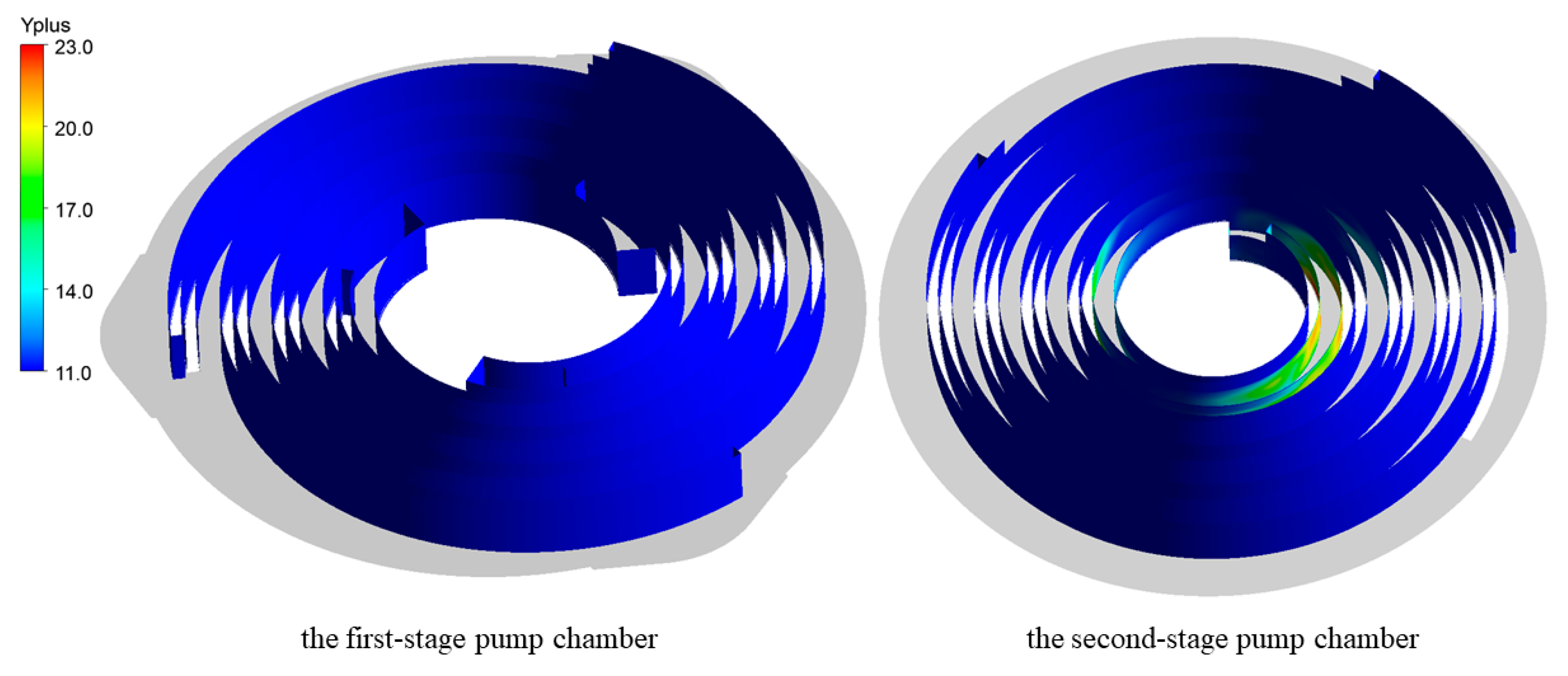
As shown in
Figure 6, the value of Y+ is in the range of 11.0 to 23.0 at the sidewalls of scroll wraps, which meets the Y+ requirement of the scalable wall functions.
3. Results and Discussion
3.1. Numerical Model Verification
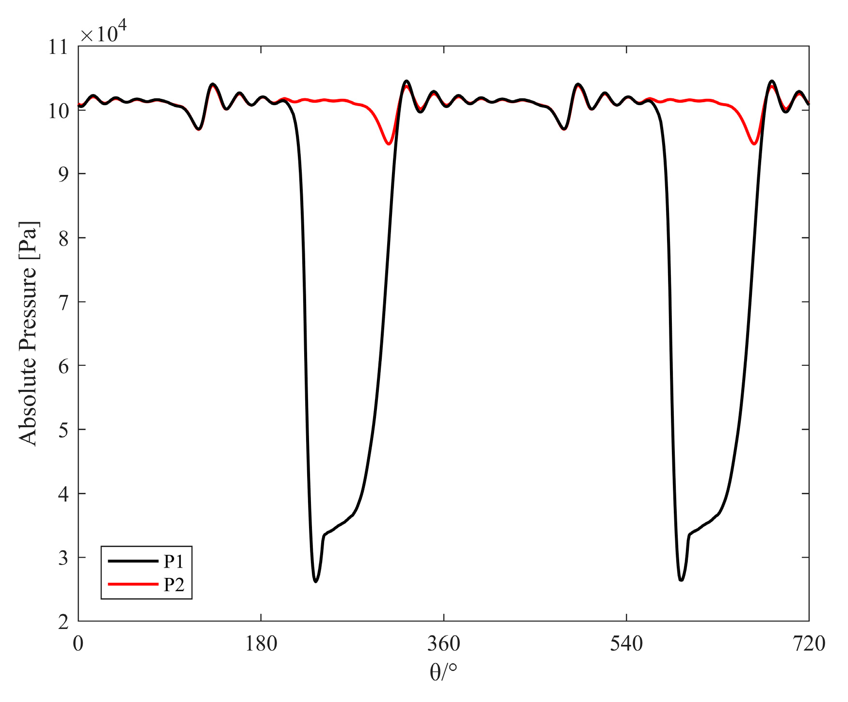
The model is cycled several times until the pressure and other parameters change periodically. The last cycle results are used for the following analyses. The periodical pressure variation at points P1 and P2 (last 2 cycles) are exhibited in
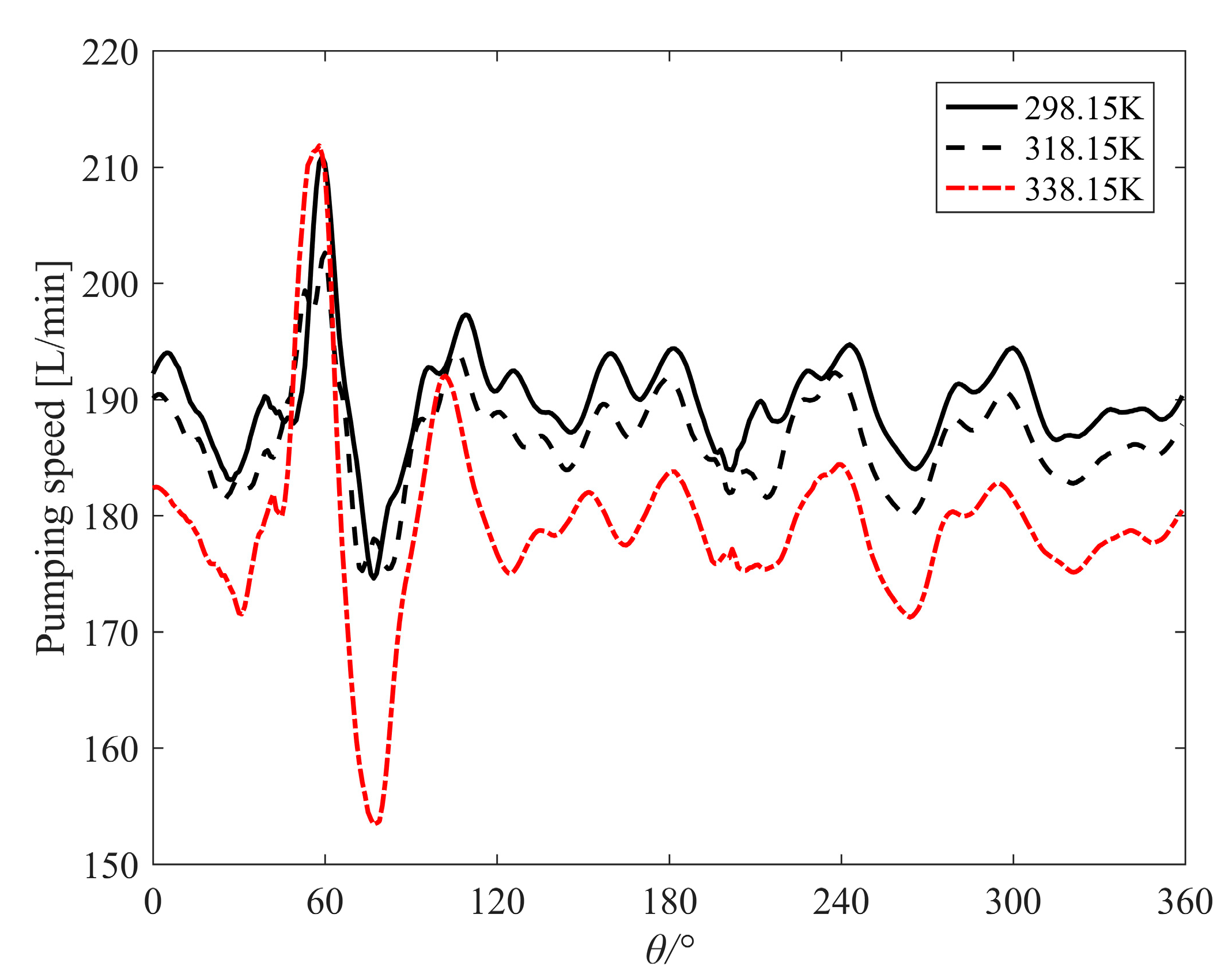
Figure 7. Model verification uses overt pumping speed curves of this pump. When the suction pressure is 1 kPa, the pumping speed is 190.00 L/min. When the wall temperature is 338.15 K, the variation of the instantaneous pumping speed of the scroll pump with the rotation angle is shown in
Figure 8. The average pumping speed
Sm of the scroll pump can be calculated as Equation (11):
The simulated pumping speed is 179.15 L/min. Compared with the experimental pumping speed, the simulation error is −5.7%, which verifies the accuracy of the numerical model and the rationality of the setting of wall temperature to some extent.
3.2. Influence of Operating Temperature on the Pumping Speed
Figure 8 shows the evolution of instantaneous pumping speed with respect to the rotation angle under different operating temperatures. It can be seen that under different operating temperatures, the pumping speed varies periodically with the rotation angle. The operating temperature obviously affects the pumping speed, and the overall change trend does not change.
The average pumping speed
Sm of the scroll pump is calculated according to Equation (11), and the results of the calculation are listed in
Table 6.
The simulation error is −5.7% when the wall temperature is 338.15 K. When the wall temperature is 298.15 K, the vacuum pump has been fully cooled. Compared with the wall temperature of 338.15 K, the pumping speed is increased by approximately 5.9722%.
The suction process of a dry scroll pump can be regarded approximately as a continuous process where heat is exchanged between gas and the pump wall. During the suction process, the heat transfer (
Qbs) from the pump wall to the gas can be expressed as Equation (12):
where Δ
T is the temperature difference between the gas and the wall,
Twall is the wall temperature,
Tgas is the gas temperature,
α is the convection heat transfer coefficient, and
As is the surface area of the suction process.
Since the surface area remains the same and the gas temperature is constant, the higher the wall temperature is, the larger the temperature difference and the heat transfer (
Qbs) are.
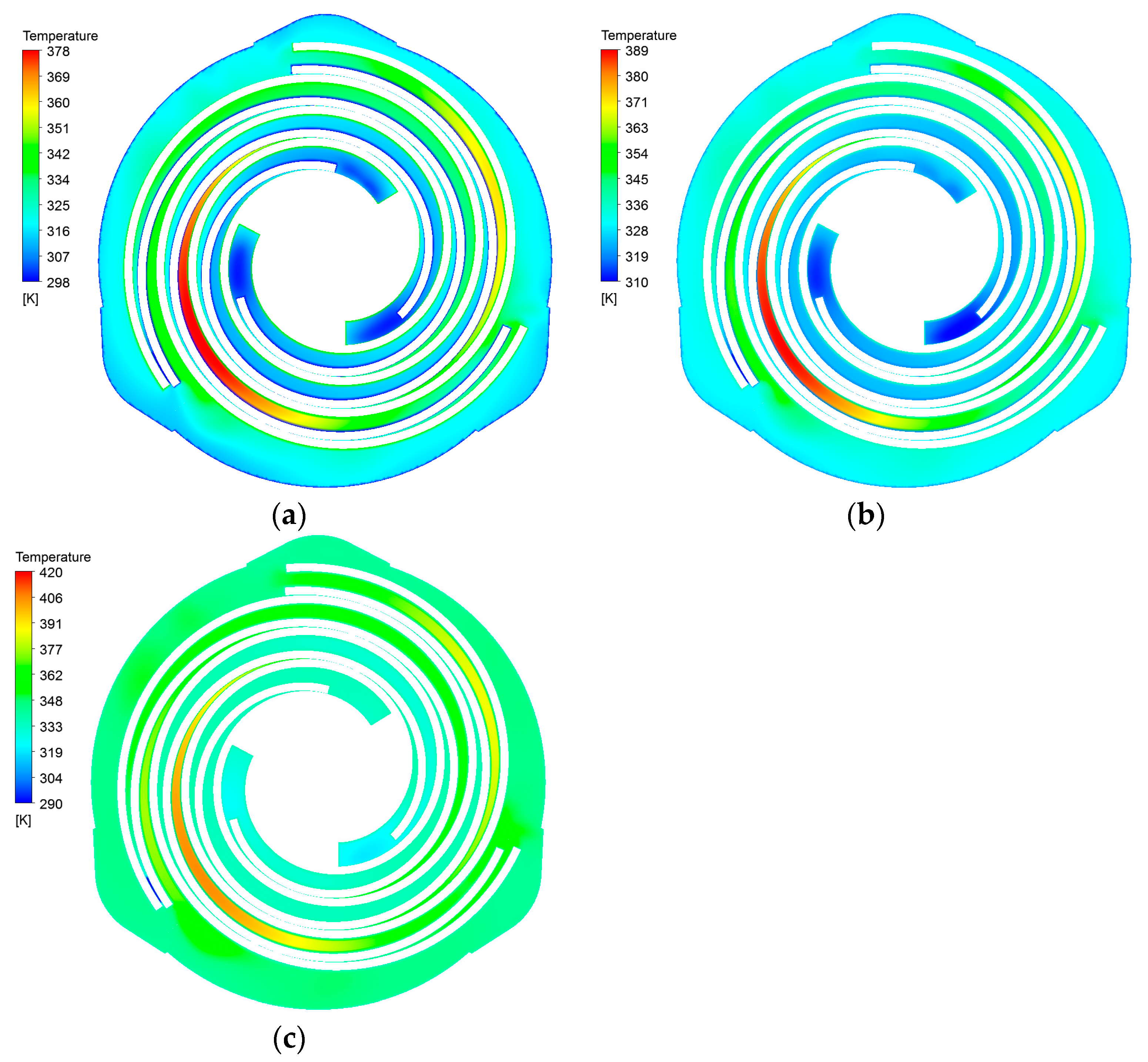
Figure 9 shows that the higher the wall temperature of the fixed scroll is, the more energy is transferred and thus the more energy is used to raise the gas temperature.
The worse the cooling capacity of the fixed scroll is, the higher the temperature of the gas in the suction chamber is. Assuming that the pumped gas is an ideal gas, it satisfies the ideal gas equation of state:
The suction pressure is always maintained at 1 kPa. After the pumped gas enters the pump, it receives heat from the surface near the suction port. The gas temperature increases and the volume expansion increases, which causes the change in pumping speed. The greater the heat dissipation capacity of the pump body, the less heat is exchanged by the pumped gas, the gas temperature change is less, the volume expansion is less, and the pumping speed is correspondingly larger.
Therefore, the purpose of improving the pumping speed under the same geometric design parameters can be realized by improving the cooling capacity of the pump body.
3.3. Influence of Operating Temperature on Torque and Power of Dry Scroll Vacuum Pump
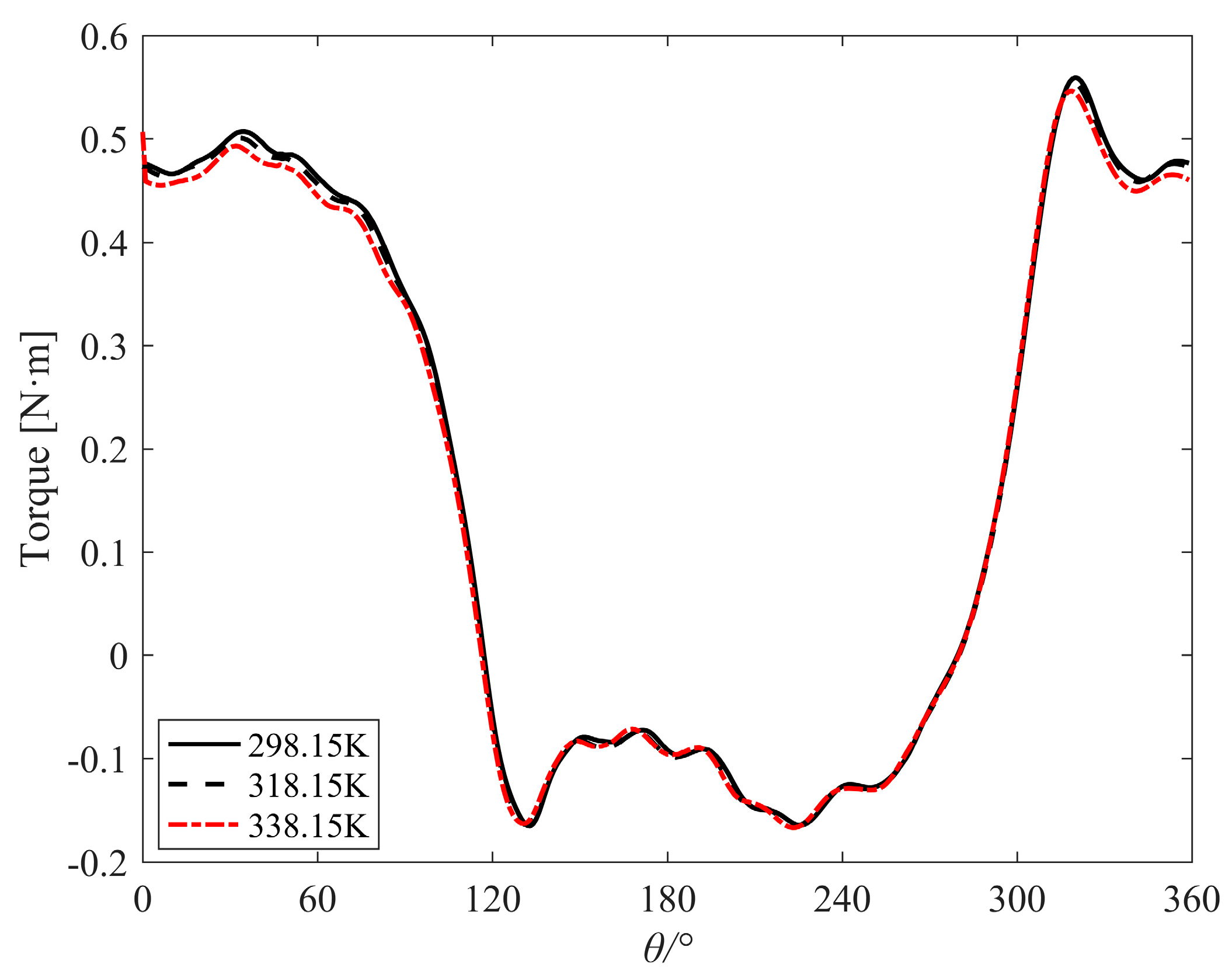
The torque of orbiting scroll is caused by the compression of instantaneous gas, and the evolution of torque with respect to orbiting angle under different operating temperatures is shown in
Figure 10. Under different operating temperatures, the torque of orbiting scroll changes with the rotation angle in the same trend. The power can be calculated from the torque and the rotational speed, and the calculation results are listed in
Table 7. The power is increased by approximately 4.32% when the operating temperature is from 338.15 K to 298.15 K.
The gas compression process of the scroll pump can be regarded as a polytropic process. According to the thermodynamic principle, the compression power (
P) can be calculated as Equation (14):
where
P1 is pump suction pressure,
P2 is pump discharge pressure,
k is the polytropic index,
k = 1.3~1.4, and
Sth is the actual pumping speed of the pump.
In this study, the inlet and outlet pressures of the pump keep constant. It can be seen from the above equation that the compression power of the gas is mainly affected by the actual pumping speed. As shown in
Table 7, the greater the heat dissipation capacity of the pump, the lower the operating temperature, the larger the pumping speed, and the larger the gas compression power.
3.4. Influence of Operating Temperature on Energy Efficiency Ratio of Dry Scroll Vacuum Pump
In recent years, the world’s energy supply has become increasingly tight, and the energy crisis continues to deepen. Under the general trend of global emission reduction development, the industry has paid more attention to resource and environmental issues and has made efforts to build a resource-saving and environment-friendly world. Energy conservation in modern society should aim to improve energy efficiency.
With the ISO 21360-1:2012 [
40] and ISO 21360-2:2012 [
41] issued, the measurement method of volumetric vacuum pump performance has been confirmed. But the energy efficiency concept for volumetric vacuum pumps has not been confirmed. The concept of energy efficiency ratio (EER) for different volume vacuum pumps should be proposed.
Pumping speed is one of the main performances of vacuum pumps. In this study, the energy efficiency ratio (EER) of the scroll vacuum pump is defined as the pumping speed (volume flow rate of gas transported) per unit of consumed power at a certain operating pressure.
The input energy of the scroll vacuum pump includes the energy consumed in the gas compression cycle, the energy consumed by mechanical friction, and the motor loss energy. The input power (
Pi) of the scroll compressor can be calculated as Equation (15):
where
ηm is mechanical efficiency,
ηm = 90%,
ηmo is motor efficiency,
ηmo = 90%.
In this study, the EER of the scroll dry pump takes the ratio of pumping speed (volume flow rate) to input power at a given suction pressure, which is calculated by Equation (16):
where
Sth is the pumping speed and
Pi is the input power.
The EER calculation results are listed in
Table 8. When the operating temperature decreases from 338.15 K to 298.15 K, the EER is increased by approximately 1.745%.
Figure 11 shows the change in EER with operating temperature.
It can be seen from
Figure 11 that the energy efficiency ratio of the scroll dry pump is gradually increased as the operating temperature is lowered. The key to improving the energy efficiency ratio is to reduce the gas compression power and increase the pumping speed so that the power per unit consumed during pump operation can transport more gas. Therefore, increasing the heat dissipation capability of the scroll pump can increase the energy efficiency ratio.
4. Conclusions
The transient numerical model of the multi-stage dry scroll vacuum pump is established by the CFD method and dynamic mesh technology. Under the suction pressure of 1000 Pa, the simulation calculation is carried out at different operating temperatures of fixed scrolls (25 °C, 45 °C, and 65 °C). The pumping speed and gas compression power are analyzed. The energy efficiency ratio of the dry scroll vacuum pump is evaluated. This research provides a transient simulation method using dynamic mesh technology for the study of dry scroll vacuum pumps. The following conclusions can be drawn.
Based on the spring smoothing method, the numerical simulation model of the multi-stage dry scroll vacuum pump is established, and the unsteady compressible flow calculation is realized. Compared with the experimental pumping speed, the pumping speed error calculated by CFD simulation is −5.7%, which verifies the accuracy of the numerical model.
Under different operating temperatures, the pumping speed and the gas compression power change significantly. With the rising pump cooling capacity, the pumping speed increases. When the reduction of the operating temperature is from 338.15 K to 298.15 K, the pumping speed is increased by approximately 5.97%. The gas compression power of the dry scroll pump is related to pumping speed. With the rising pump cooling capacity, the gas compression power increases. The gas compression power is increased by approximately 4.32% when the operating temperature is reduced from 338.15 K to 298.15 K. With the same geometric design parameters, by improving the cooling capacity of the pump body, the pumping speed can be increased, and gas compression power can be reduced.
The energy efficiency ratio of the dry scroll pump is proposed. The energy efficiency ratio of the scroll pump is related to the operating temperature of the pump. With decreasing the temperature of the pump body, the energy efficiency ratio increased. The energy efficiency ratio is increased by approximately 1.745% when the operating temperature is reduced from 338.15 K to 298.15 K.
This research can provide a theoretical basis for the design and application of the cooling system of the dry scroll vacuum pump, and these results are of great significance to the structural design and optimization of the dry scroll vacuum pump.


