
Wideband Vibro-Acoustic Modulation for Crack Detection in Wind Turbine Blades


Abstract
:Featured Application
Abstract
1. Introduction
2. VAM Model for Detecting Cracks in WT Blades
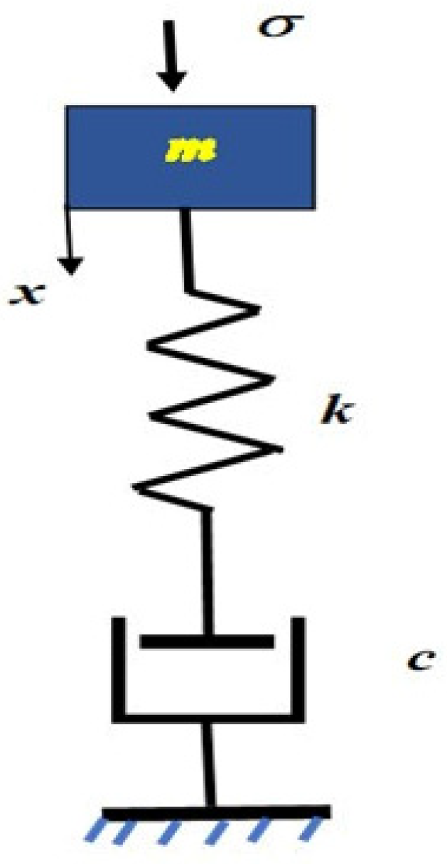
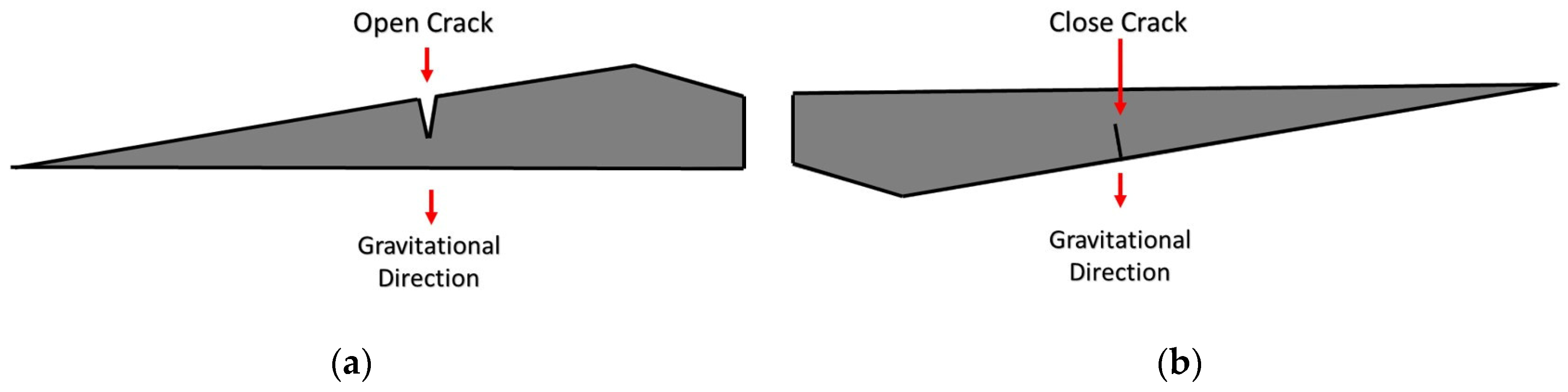
2.1. Description of the Proposed Model for WT Blade Crack Detection
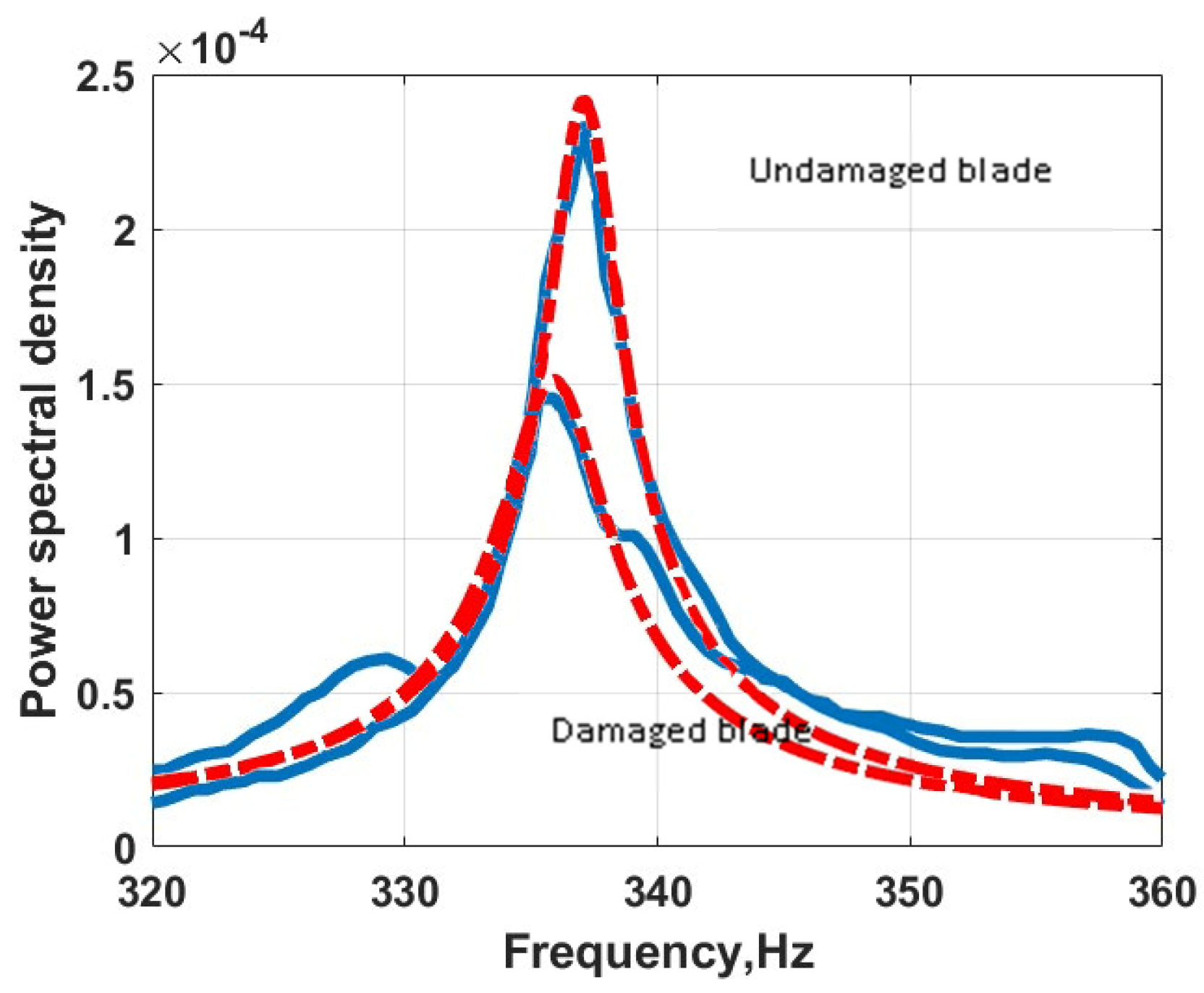
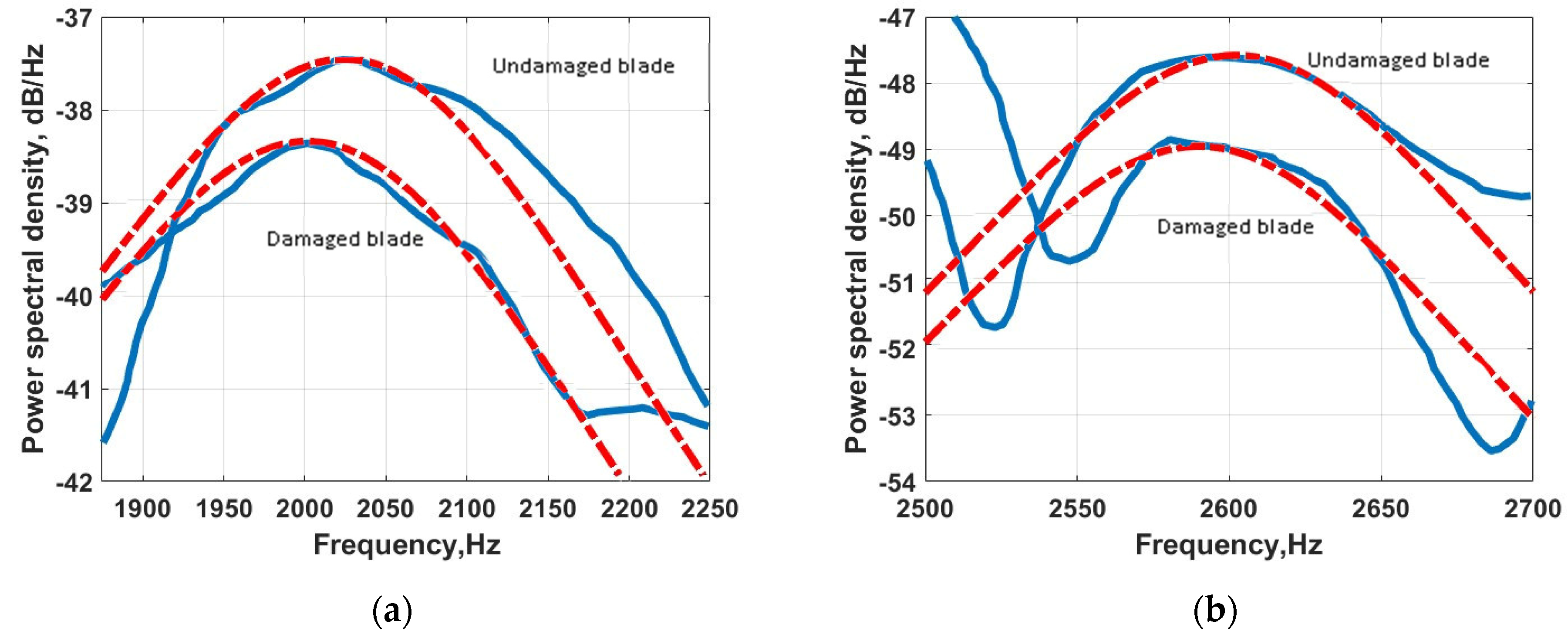
2.2. Extract Non-Linear Parameter Derived from the Published Data
2.3. Comparison between Traditional VAM (Active Vibration) and Proposed VAM (Passive Vibration)
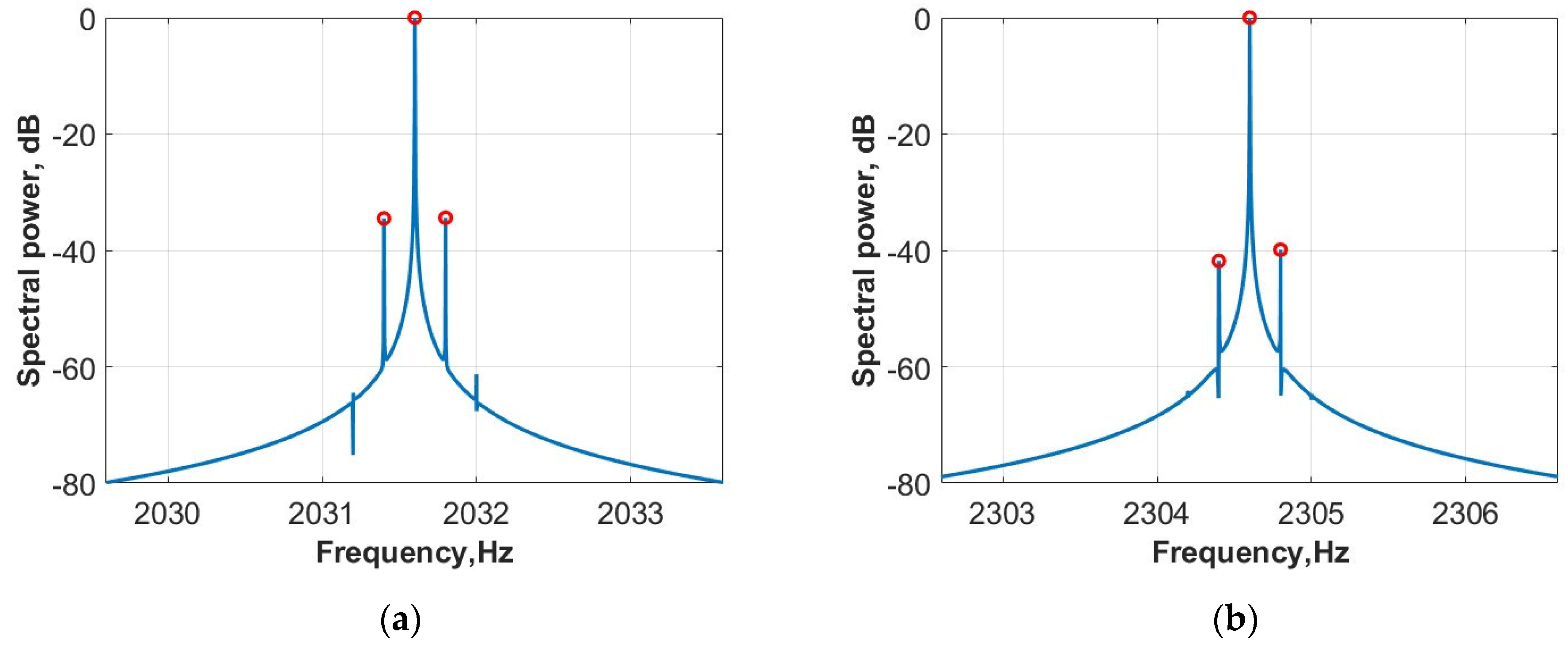
2.3.1. Active Method
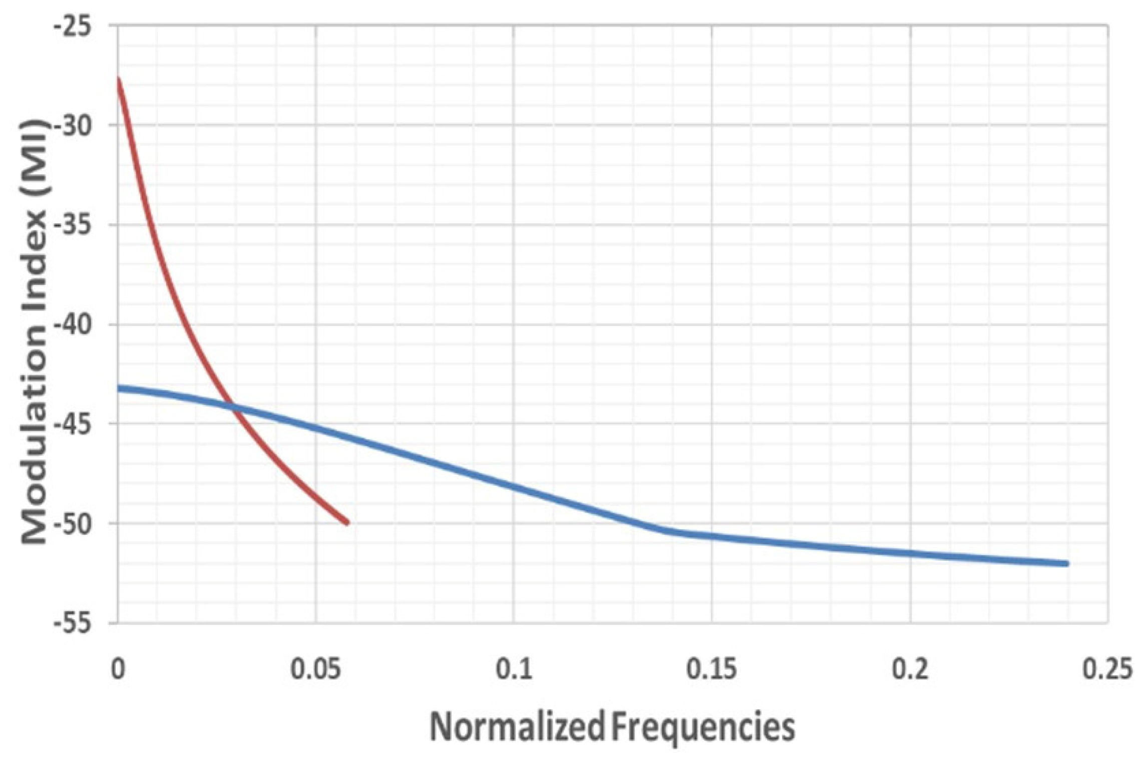
2.3.2. Passive VAM
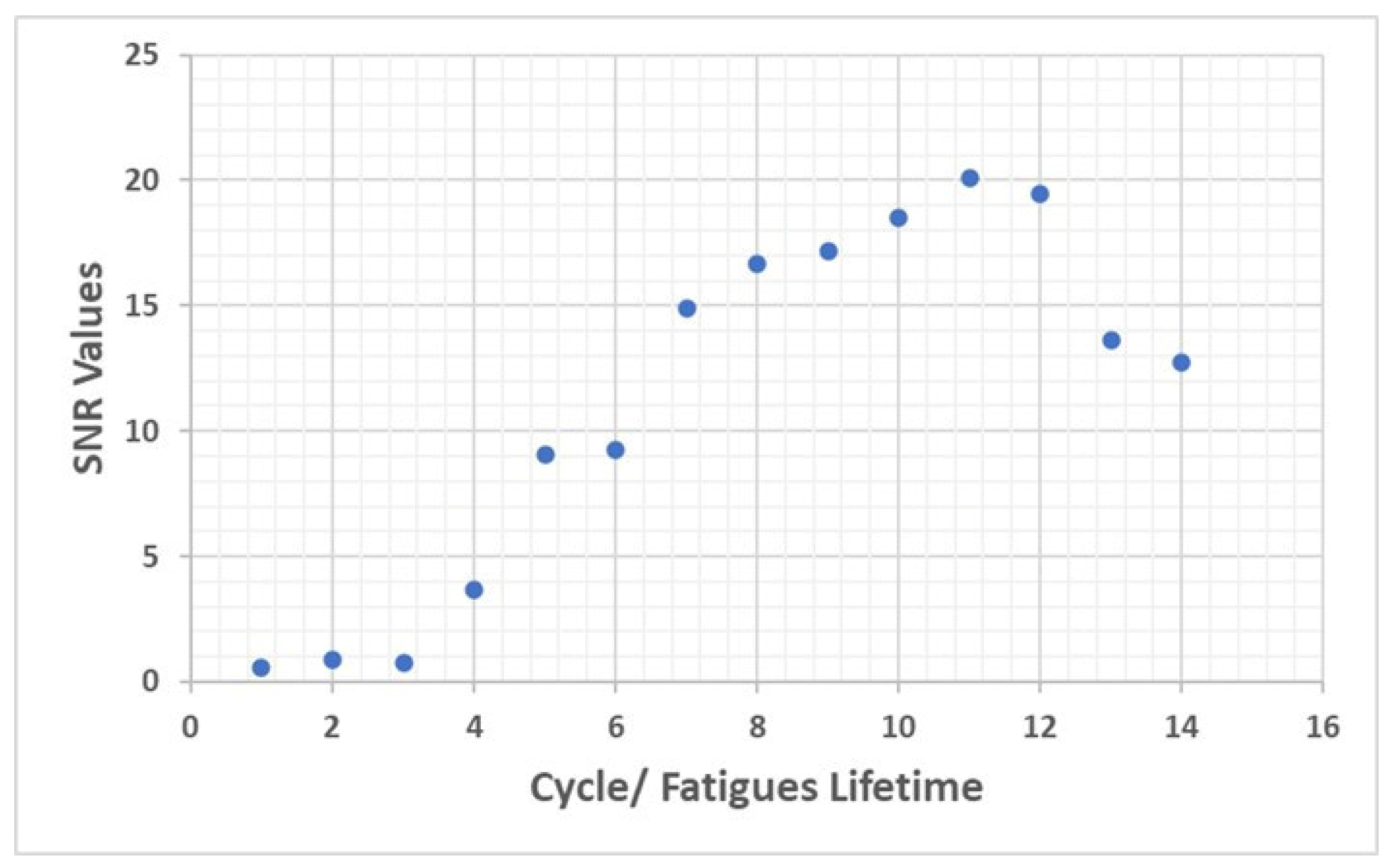
3. Laboratory Investigation of Damage Accumulation in Steel Due to Cyclic Loading
4. Conclusions
Author Contributions
Funding
Institutional Review Board Statement
Informed Consent Statement
Data Availability Statement
Conflicts of Interest
References
- Adams, D.; White, J.; Rumsey, M.; Farrar, C. Structural Health Monitoring of Wind Turbines: Method and Application to a HAWT. Wind. Energy 2011, 14, 603–623. [Google Scholar] [CrossRef]
- Ciang, C.C.; Lee, J.-R.; Bang, H. Structural Health Monitoring for a Wind Turbine System: A Review of Damage Detection Methods. Meas. Sci. Technol. 2008, 19, 122001. [Google Scholar] [CrossRef]
- Du, Y.; Zhou, S.; Jing, X.; Peng, Y.; Wu, H.; Kwok, N. Damage Detection Techniques for Wind Turbine Blades: A Review. Mech. Syst. Signal Process. 2020, 141, 106445. [Google Scholar] [CrossRef]
- Ostachowicz, W.; Güemes, A. New Trends in Structural Health Monitoring; Springer Science & Business Media: New York, NY, USA, 2013; ISBN 978-3-7091-1390-5. [Google Scholar]
- Doliński, Ł.; Krawczuk, M.; Żak, A. Detection of Delamination in Laminate Wind Turbine Blades Using One-Dimensional Wavelet Analysis of Modal Responses. Shock. Vib. 2018, 2018, e4507879. [Google Scholar] [CrossRef]
- Fremmelev, M.A.; Ladpli, P.; Orlowitz, E.; Bernhammer, L.O.; McGugan, M.; Branner, K. Structural Health Monitoring of 52-Meter Wind Turbine Blade: Detection of Damage Propagation during Fatigue Testing. Data-Centric Eng. 2022, 3, e22. [Google Scholar] [CrossRef]
- García, D.; Tcherniak, D. An Experimental Study on the Data-Driven Structural Health Monitoring of Large Wind Turbine Blades Using a Single Accelerometer and Actuator. Mech. Syst. Signal Process. 2019, 127, 102–119. [Google Scholar] [CrossRef]
- Ghoshal, A.; Sundaresan, M.J.; Schulz, M.J.; Frank Pai, P. Structural Health Monitoring Techniques for Wind Turbine Blades. J. Wind. Eng. Ind. Aerodyn. 2000, 85, 309–324. [Google Scholar] [CrossRef]
- Hoell, S.; Omenzetter, P. Improved Damage Detectability in a Wind Turbine Blade by Optimal Selection of Vibration Signal Correlation Coefficients. Struct. Health Monit. 2016, 15, 685–705. [Google Scholar] [CrossRef]
- Kim, S.; Adams, D.E.; Sohn, H.; Rodriguez-Rivera, G.; Myrent, N.; Bond, R.; Vitek, J.; Carr, S.; Grama, A.; Meyer, J.J. Crack Detection Technique for Operating Wind Turbine Blades Using Vibro-Acoustic Modulation. Struct. Health Monit. 2014, 13, 660–670. [Google Scholar] [CrossRef]
- Myrent, N.J.; Adams, D.E.; Rodriguez-Rivera, G.; Ulybyshev, D.A.; Vitek, J.; Blanton, E.; Kalibera, T. A Robust Algorithm to Detecting Wind Turbine Blade Health Using Vibro-Acoustic Modulation and Sideband Spectral Analysis. In Proceedings of the 33rd Wind Energy Symposium, Kissimmee, FL, USA, 5–9 January 2015; American Institute of Aeronautics and Astronautics: Reston, VA, USA, 2015. [Google Scholar]
- Ou, Y.; Tatsis, K.E.; Dertimanis, V.K.; Spiridonakos, M.D.; Chatzi, E.N. Vibration-Based Monitoring of a Small-Scale Wind Turbine Blade under Varying Climate Conditions. Part I: An Experimental Benchmark. Struct. Control. Health Monit. 2021, 28, e2660. [Google Scholar] [CrossRef]
- Panagiotopoulos, A.I.; Tcherniak, D.; Fassois, S.D. Damage Detection on an Operating Wind Turbine Blade via a Single Vibration Sensor: A Feasibility Study. In European Workshop on Structural Health Monitoring; Rizzo, P., Milazzo, A., Eds.; Springer International Publishing: Cham, Switzerland, 2021; pp. 405–414. [Google Scholar]
- Tcherniak, D. Rotor Anisotropy as a Blade Damage Indicator for Wind Turbine Structural Health Monitoring Systems. Mech. Syst. Signal Process. 2016, 74, 183–198. [Google Scholar] [CrossRef]
- Tcherniak, D.; Mølgaard, L.L. Active Vibration-Based Structural Health Monitoring System for Wind Turbine Blade: Demonstration on an Operating Vestas V27 Wind Turbine. Struct. Health Monit. 2017, 16, 536–550. [Google Scholar] [CrossRef]
- Tcherniak, D.; Mølgaard, L.L. Vibration-Based SHM System: Application to Wind Turbine Blades. J. Phys. Conf. Ser. 2015, 628, 012072. [Google Scholar] [CrossRef]
- Ulriksen, M.D.; Tcherniak, D.; Hansen, L.M.; Johansen, R.J.; Damkilde, L.; Frøyd, L. In-Situ Damage Localization for a Wind Turbine Blade through Outlier Analysis of Stochastic Dynamic Damage Location Vector-Induced Stress Resultants. Struct. Health Monit. 2017, 16, 745–761. [Google Scholar] [CrossRef]
- Wang, Y.; Liang, M.; Xiang, J. Damage Detection Method for Wind Turbine Blades Based on Dynamics Analysis and Mode Shape Difference Curvature Information. Mech. Syst. Signal Process. 2014, 48, 351–367. [Google Scholar] [CrossRef]
- Ulriksen, M.D.; Tcherniak, D.; Damkilde, L. Damage Detection in an Operating Vestas V27 Wind Turbine Blade by Use of Outlier Analysis. In Proceedings of the 2015 IEEE Workshop on Environmental, Energy, and Structural Monitoring Systems (EESMS) Proceedings, Trento, Italy, 9–10 July 2015; pp. 50–55. [Google Scholar]
- Bull, T.; Ulriksen, M.D.; Tcherniak, D. The Effect of Environmental and Operational Variabilities on Damage Detection in Wind Turbine Blades: 9th European Workshop on Structural Health Monitoring. In Proceedings of the 9th European Workshop on Structural Health Monitoring, Manchester, UK, 10–13 July 2018. [Google Scholar]
- Li, H.; Zhou, W.; Xu, J. Structural Health Monitoring of Wind Turbine Blades. In Wind Turbine Control and Monitoring; Luo, N., Vidal, Y., Acho, L., Eds.; Advances in Industrial Control; Springer International Publishing: Cham, Switzerland, 2014; pp. 231–265. ISBN 978-3-319-08413-8. [Google Scholar]
- Pacheco-Chérrez, J.; Probst, O. Vibration-Based Damage Detection in a Wind Turbine Blade through Operational Modal Analysis under Wind Excitation. Mater. Today Proc. 2022, 56, 291–297. [Google Scholar] [CrossRef]
- Requeson, O.R.; Tcherniak, D.; Larsen, G.C. Comparative Study of OMA Applied to Experimental and Simulated Data from an Operating Vestas V27 Wind Turbine: 6th International Operational Modal Analysis Conference. In Proceedings of the 6th International Operational Modal Analysis Conference (IOMAC 2015), Gijon, Spain, 12–14 May 2015. [Google Scholar]
- Tang, H.; Ling, S.; Wan, C.; Xue, S. Experimental Verification of the Statistical Time-Series Methods for Diagnosing Wind Turbine Blades Damage. Int. J. Str. Stab. Dyn. 2019, 19, 1940008. [Google Scholar] [CrossRef]
- Liu, X.; Lu, C.; Liang, S.; Godbole, A.; Chen, Y. Vibration-Induced Aerodynamic Loads on Large Horizontal Axis Wind Turbine Blades. Appl. Energy 2017, 185, 1109–1119. [Google Scholar] [CrossRef]
- Eldeeb, A.E.; El-Arabi, M.E.; Hussein, B.A. Effect of Cracks in Wind Turbine Blades on Natural Frequencies During Operation. J. Eng. Appl. Sci. 2020, 67, 1995–2012. [Google Scholar]
- Kim, H.-C.; Kim, M.-H.; Choe, D.-E. Structural Health Monitoring of Towers and Blades for Floating Offshore Wind Turbines Using Operational Modal Analysis and Modal Properties with Numerical-Sensor Signals. Ocean. Eng. 2019, 188, 106226. [Google Scholar] [CrossRef]
- Lorenzo, E.D.; Petrone, G.; Manzato, S.; Peeters, B.; Desmet, W.; Marulo, F. Damage Detection in Wind Turbine Blades by Using Operational Modal Analysis. Struct. Health Monit. 2016, 15, 289–301. [Google Scholar] [CrossRef]
- Tcherniak, D.; Chauhan, S.; Hansen, M.H. Applicability Limits of Operational Modal Analysis to Operational Wind Turbines. In Structural Dynamics and Renewable Energy; Proulx, T., Ed.; Springer: New York, NY, USA, 2011; Volume 1, pp. 317–327. [Google Scholar]
- Ulriksen, M.D.; Tcherniak, D.; Kirkegaard, P.H.; Damkilde, L. Operational Modal Analysis and Wavelet Transformation for Damage Identification in Wind Turbine Blades. Struct. Health Monit. 2016, 15, 381–388. [Google Scholar] [CrossRef]
- Sarrafi, A.; Mao, Z.; Niezrecki, C.; Poozesh, P. Vibration-Based Damage Detection in Wind Turbine Blades Using Phase-Based Motion Estimation and Motion Magnification. J. Sound Vib. 2018, 421, 300–318. [Google Scholar] [CrossRef]
- Buck, O.; Morris, W.L.; Richardson, J.M. Acoustic Harmonic Generation at Unbonded Interfaces and Fatigue Cracks. Appl. Phys. Lett. 1978, 33, 371–373. [Google Scholar] [CrossRef]
- Morris, W.L.; Buck, O.; Inman, R.V. Acoustic Harmonic Generation Due to Fatigue Damage in High-strength Aluminum. J. Appl. Phys. 1979, 50, 6737–6741. [Google Scholar] [CrossRef]
- Guyer, R.A.; Johnson, P.A. Nonlinear Mesoscopic Elasticity: The Complex Behaviour of Rocks, Soil, Concrete; John Wiley & Sons: Hoboken, NJ, USA, 2009; ISBN 978-3-527-40703-3. [Google Scholar]
- Zheng, Y.; Maev, R.G.; Solodov, I.Y. Review / Sythèse Nonlinear Acoustic Applications for Material Characterization: A Review. Can. J. Phys. 2000, 77, 927–967. [Google Scholar] [CrossRef]
- Broda, D.; Staszewski, W.J.; Martowicz, A.; Uhl, T.; Silberschmidt, V.V. Modelling of Nonlinear Crack–Wave Interactions for Damage Detection Based on Ultrasound—A Review. J. Sound Vib. 2014, 333, 1097–1118. [Google Scholar] [CrossRef]
- Gurbatov, S.N.; Rudenko, O.V.; Saichev, A.I. Types of Acoustic Nonlinearities and Methods of Nonlinear Acoustic Diagnostics. In Waves and Structures in Nonlinear Nondispersive Media: General Theory and Applications to Nonlinear Acoustics; Gurbatov, S.N., Rudenko, O.V., Saichev, A.I., Eds.; Nonlinear Physical Science; Springer: Berlin, Heidelberg, 2011; pp. 271–307. ISBN 978-3-642-23617-4. [Google Scholar]
- Zaitsev, V.Y. Nonlinear Acoustics in Studies of Structural Features of Materials. MRS Bull. 2019, 44, 350–360. [Google Scholar] [CrossRef]
- Sutin, A.M.; Salloum, H. Interaction of Acoustic and Electromagnetic Waves in Nondestructive Evaluation and Medical Applications. Radiophys Quantum El 2020, 63, 40–54. [Google Scholar] [CrossRef]
- Solodov, I. Nonlinear Acoustic NDT: Approaches, Methods, and Applications. In Proceedings of the NDT in Progress, 5th International Workshop of NDT Experts, Prague, Czech Republic, 12–14 October 2009; Brno University of Technology & Czech Society for Non-Destructive Testing: Brno, Czech Republic, 2009. [Google Scholar]
- Kundu, T.; Eiras, J.N.; Li, W.; Liu, P.; Sohn, H.; Payá, J. Fundamentals of Nonlinear Acoustical Techniques and Sideband Peak Count. In Nonlinear Ultrasonic and Vibro-Acoustical Techniques for Nondestructive Evaluation; Kundu, T., Ed.; Springer International Publishing: Cham, Switzerland, 2019; pp. 1–88. ISBN 978-3-319-94476-0. [Google Scholar]
- Castellano, A.; Fraddosio, A.; Piccioni, M.D.; Kundu, T. Linear and Nonlinear Ultrasonic Techniques for Monitoring Stress-Induced Damages in Concrete. J. Nondestruct. Eval. Diagn. Progn. Eng. Syst. 2021, 4, 041001. [Google Scholar] [CrossRef]
- Liu, P.; Sohn, H. Damage Detection Using Sideband Peak Count in Spectral Correlation Domain. J. Sound Vib. 2017, 411, 20–33. [Google Scholar] [CrossRef]
- Alnuaimi, H.; Amjad, U.; Park, S.; Russo, P.; Lopresto, V.; Kundu, T. An Improved Nonlinear Ultrasonic Technique for Detecting and Monitoring Impact Induced Damage in Composite Plates. Ultrasonics 2022, 119, 106620. [Google Scholar] [CrossRef] [PubMed]
- Hu, H.F.; Staszewski, W.J.; Hu, N.Q.; Jenal, R.B.; Qin, G.J. Crack Detection Using Nonlinear Acoustics and Piezoceramic Transducers—Instantaneous Amplitude and Frequency Analysis. Smart Mater. Struct. 2010, 19, 065017. [Google Scholar] [CrossRef]
- Li, N.; Wang, F.; Song, G. New Entropy-Based Vibro-Acoustic Modulation Method for Metal Fatigue Crack Detection: An Exploratory Study. Measurement 2020, 150, 107075. [Google Scholar] [CrossRef]
- Ballad, E.M.; Vezirov, S.Y.; Pfleiderer, K.; Solodov, I.Y.; Busse, G. Nonlinear Modulation Technique for NDE with Air-Coupled Ultrasound. Ultrasonics 2004, 42, 1031–1036. [Google Scholar] [CrossRef]
- Lee, S.E.; Lim, H.J.; Sohn, H.; Hong, J.W. Excitation Conditions for Nonlinear Ultrasonic Wave Modulation Technique. In Kkhtcnn; Chulalongkorn University: Bangkok, Thailand, 2015. [Google Scholar]
- Dziedziech, K.; Klepka, A.; Roemer, J.; Pieczonka, L. Experimental Study of Thermo-Acoustic Wave Modulation in a Cracked Plate. J. Sound Vib. 2021, 498, 115970. [Google Scholar] [CrossRef]
- Golchinfar, B.; Ramezani, M.G.; Donskoy, D.; Saboonchi, H. Vibro-Acoustic Modulation Technique Comparison with Conventional Nondestructive Evaluation Methods. In Health Monitoring of Structural and Biological Systems XIV; S.PIE: Philadelphia, PA, USA, 2020; Volume 11381, pp. 187–198. [Google Scholar]
- Saito, A.; Castanier, M.P.; Pierre, C.; Poudou, O. Efficient Nonlinear Vibration Analysis of the Forced Response of Rotating Cracked Blades. J. Comput. Nonlinear Dyn. 2008, 4, 011005. [Google Scholar] [CrossRef]
- Yang, L.; Mao, Z.; Wu, S.; Chen, X.; Yan, R. Nonlinear Dynamic Behavior of Rotating Blade with Breathing Crack. Front. Mech. Eng. 2021, 16, 196–220. [Google Scholar] [CrossRef]
- Liu, C.; Jiang, D.; Chu, F. Influence of Alternating Loads on Nonlinear Vibration Characteristics of Cracked Blade in Rotor System. J. Sound Vib. 2015, 353, 205–219. [Google Scholar] [CrossRef]
- Sinou, J.-J. A Review of Damage Detection and Health Monitoring of Mechanical Systems from Changes in the Measurement of Linear and Non-linear Vibrations. In Mechanical Vibrations: Measurement, Effects and Control; Nova Science Publishers, Inc.: New York, NY, USA, 2009; pp. 643–702. [Google Scholar]
- Agarwal, R.C.; Chander, V.; Pillai, S.P. Issues in the Design of Towed Array Sonar Systems. IETE Tech. Rev. 1993, 10, 93–99. [Google Scholar] [CrossRef]
- Donskoy, D.; Golchinfar, B.; Ramezani, M.; Rutner, M.; Hassiotis, S. Vibro-Acoustic Amplitude and Frequency Modulations during Fatigue Damage Evolution. AIP Conf. Proc. 2019, 2102, 040004. [Google Scholar] [CrossRef]
- Kummert, A. Fuzzy Technology Implemented in Sonar Systems. IEEE J. Ocean. Eng. 1993, 18, 483–490. [Google Scholar] [CrossRef]
- Alnutayfat, A.; Sutin, A.; Liu, D. Vibroacoustic Modulation of Wideband Vibrations and Its Possible Application for Windmill Blade Diagnostics. Int. J. Civ. Environ. Eng. 2023, 17, 31–36. [Google Scholar]
- Alnutayfat, A.; Hassiotis, S.; Liu, D.; Sutin, A. Sideband Peak Count in a Vibro-Acoustic Modulation Method for Crack Detection. Acoustics 2022, 4, 74–86. [Google Scholar] [CrossRef]


| Investigated Blade | Damage Description | Type of Test (Operational WT, Lab, Simulation) Vibration Excitation Method | Res. Frequency for Damaged Blade, Hz | Frequency Shift Ratio , % | Reference |
|---|---|---|---|---|---|
| A 1.02-m WT blade made of fiber-glass material | Crack on the blade edge, depth of 30 mm. |
| 22.2 | 2.6 | [18] |
| 88.8 | 0.7 | ||||
| 190.2 | 0.94 | ||||
| 339.6 | 1.9 | ||||
| A 6.5-m all fiberglass blade | Buckling refers to the structural failure that occurs due to significant deformation, changing the geometric arrangement of the structure. |
| 3.20 | 18.5 | [28] |
| 6.09 | 23.1 | ||||
| 9.98 | 11.9 | ||||
| 22.93 | 7.5 | ||||
| An SSP 34-m blade | A trailing edge debonding method. Debonding was started by drilling holes to remove glue at the trailing edge, and it was then increased using a hammer and chisel, resulting in a 1200 mm of damage |
| 1.35 | 0.74 | [30] |
| 9.17 | 0.22 | ||||
| 17.99 | 0.5 | ||||
| A 1.75 m long blade | Cracks of varying lengths and locations on the blades. How were cracks produced? |
| 12.4 | 12 | [12] |
| 43.8 | 9 | ||||
| 112.9 | 5 | ||||
| A 5-m blade length | Cracks of varying sizes (small, medium, and large) in a WT blade at 72% of the blade’s length. |
| 4.85 | 0.2 | [26] |
| 21.78 | 0.3 | ||||
| 56 | 0.9 | ||||
| A 52-m WT blade | Artificial cracking was induced on a 52-m blade through the utilization of an angle grinder to cut through the laminate’s thickness. |
| 2001.7 | 1.13 | [6] |
| 2590 | 0.5 | ||||
| An 8-foot section | A steel plate weighing 12 pounds was attached to the lower left edge of the blade to emulate the reversible crack. |
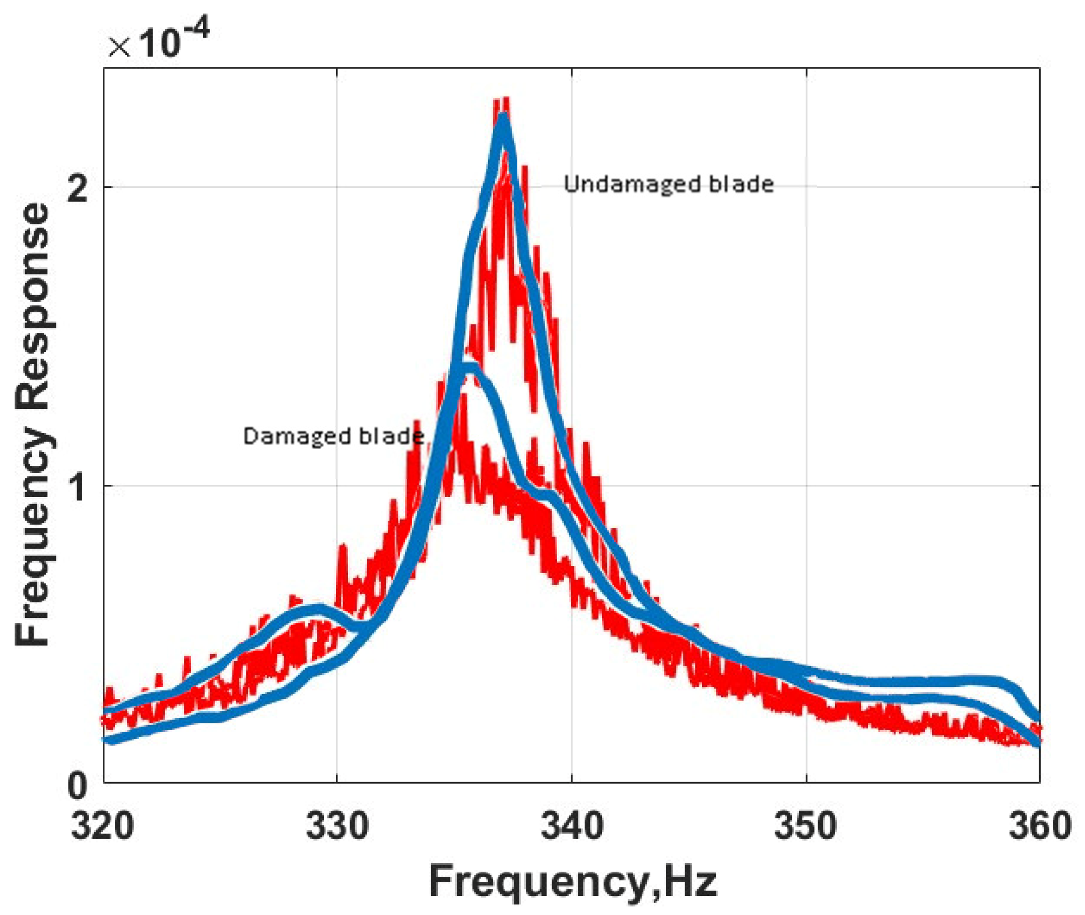
| 335.85 | 0.4 | [8] |
| A 1300-cm Vestas V27 WT blade | In the blade used in the three-month field tests, an artificial defect was introduced to simulate adhesive joint failure between the skins, specifically using a trailing edge opening. |
| 990 | 1 | [13] |
| Test Data | f1 | f2 | Q1 | Q2 | α | β |
|---|---|---|---|---|---|---|
| eight-foot section of WT blade | 335.85 HZ | 337.1 HZ | 81.2 | 111.5 | 0.0004 | 0.0272 |
| the 52-m WT blade in bands of 1900 Hz to 2250 Hz. | 2001.7 Hz | 2024.6 HZ | 5.7 | 5.9 | 0.00113 | 0.003 |
| The 52-m WT blade in band 2500 Hz to 2700 Hz | 2590 HZ | 2602.1 HZ | 14.6 | 14.8 | 0.0005 | 0.00135 |
| Parameters | Case 1 | Case 2 | Case 3 |
|---|---|---|---|
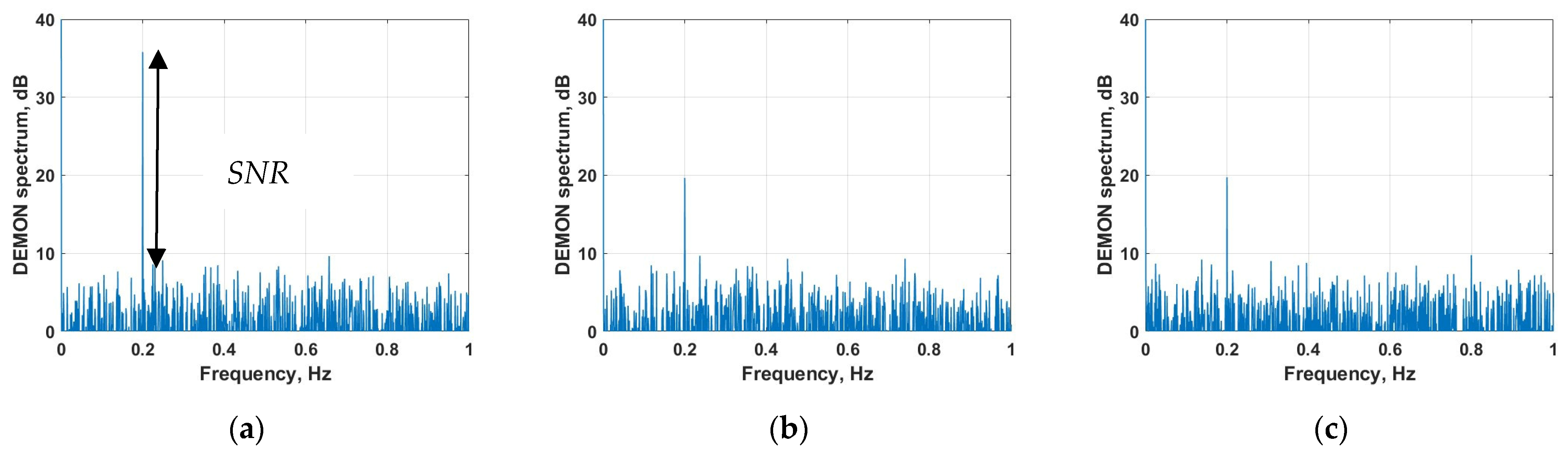
| SNR for wide band | 28 | 19.9 | 10.5 |
| SNR for wide band for β = 0 | −4 | 14.25 | 7.33 |
| MI for harmonic | −32.29 | −43.45 | −42.477 |
| MI for harmonic for β = 0 | −32.993 | −43.68 | −42.491 |
Disclaimer/Publisher’s Note: The statements, opinions and data contained in all publications are solely those of the individual author(s) and contributor(s) and not of MDPI and/or the editor(s). MDPI and/or the editor(s) disclaim responsibility for any injury to people or property resulting from any ideas, methods, instructions or products referred to in the content. |
© 2023 by the authors. Licensee MDPI, Basel, Switzerland. This article is an open access article distributed under the terms and conditions of the Creative Commons Attribution (CC BY) license (https://creativecommons.org/licenses/by/4.0/).
Share and Cite
Alnutayfat, A.; Sutin, A. Wideband Vibro-Acoustic Modulation for Crack Detection in Wind Turbine Blades. Appl. Sci. 2023, 13, 9570. https://doi.org/10.3390/app13179570
Alnutayfat A, Sutin A. Wideband Vibro-Acoustic Modulation for Crack Detection in Wind Turbine Blades. Applied Sciences. 2023; 13(17):9570. https://doi.org/10.3390/app13179570
Chicago/Turabian StyleAlnutayfat, Abdullah, and Alexander Sutin. 2023. "Wideband Vibro-Acoustic Modulation for Crack Detection in Wind Turbine Blades" Applied Sciences 13, no. 17: 9570. https://doi.org/10.3390/app13179570
APA StyleAlnutayfat, A., & Sutin, A. (2023). Wideband Vibro-Acoustic Modulation for Crack Detection in Wind Turbine Blades. Applied Sciences, 13(17), 9570. https://doi.org/10.3390/app13179570