


Investigation of the Motion Characteristics of Parts on a Platform Subjected to Planar Oscillations

 ,
,  ,
,  ,
, 
Abstract
:1. Introduction
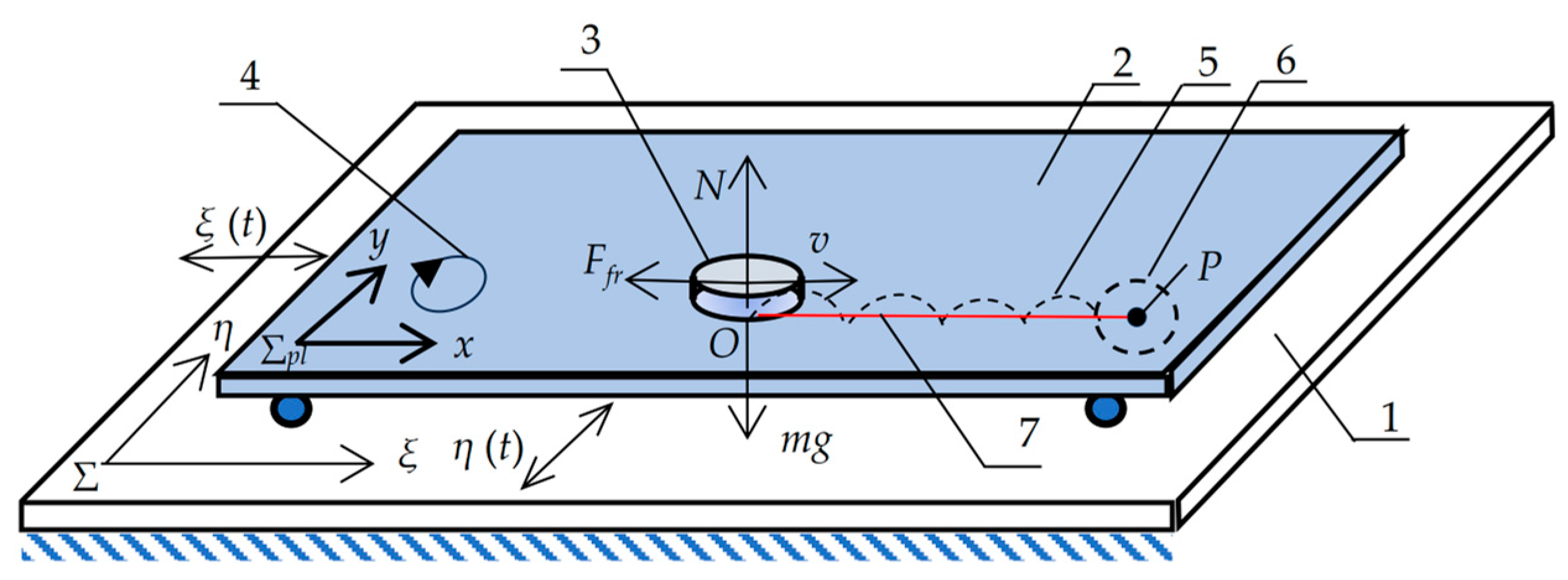
2. Dynamic and Mathematical Models of the Motion of a Part on a Horizontally Oscillating Platform
3. Modeling Results
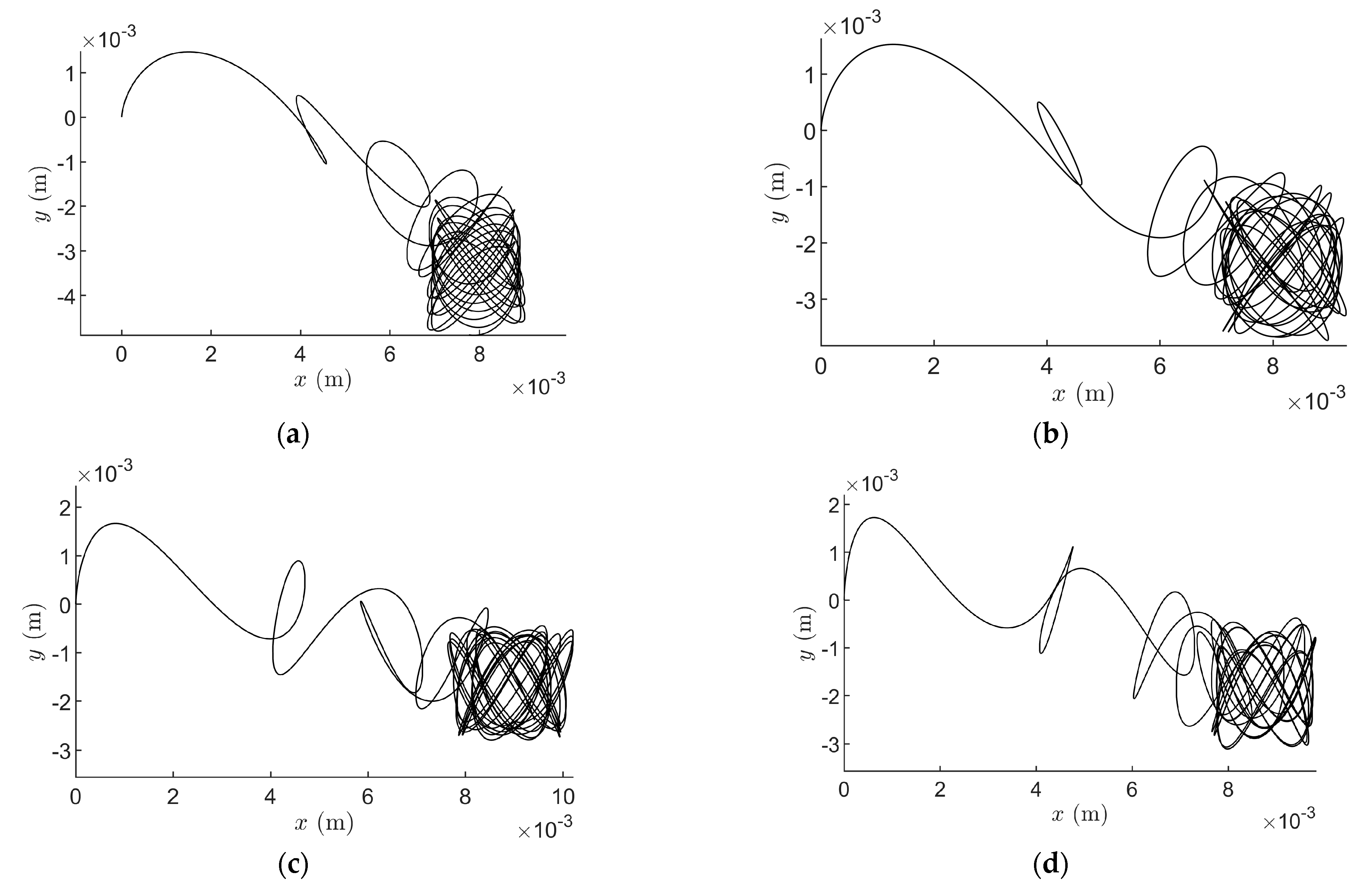
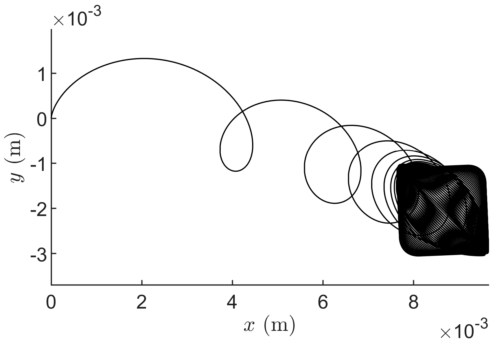
- When the platform is excited in two perpendicular directions by sinusoidal waves of the same amplitude (Ax = Ay), and the phase shift between the perpendicular components is π/2. In this case, the platform moves in a circular trajectory.
- When the platform is excited in two perpendicular directions by sinusoidal waves of different amplitudes (Ax ≠ Ay), and the phase shift between the perpendicular components is π/2. In this case, the platform moves in an elliptical trajectory.
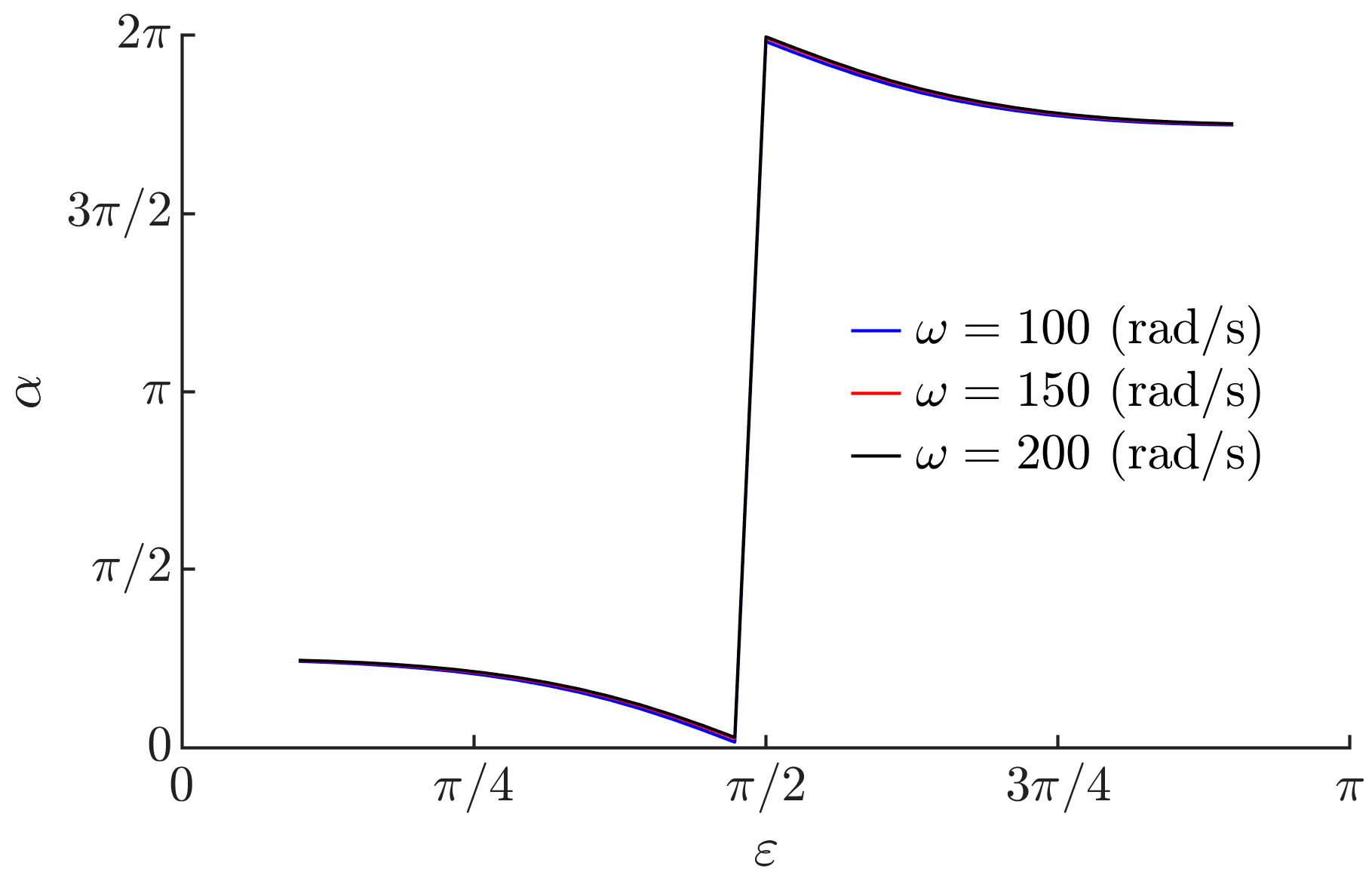
- When the platform is excited in two perpendicular directions by sinusoidal waves of the same amplitude (Ax = Ay), and the phase shift between the perpendicular components varies in the range of π/10 ≤ ε ˂ 9π/10. These phase shift values are chosen since the part moves in a straight path at phase shift values of 0 and π, and that is not suitable for positioning. When the phase shift varies in the range of π/10 ≤ ε ˂ π/2, the motion of the platform follows inclined elliptical trajectories; then, at ε = π/2, the trajectory of the platform becomes circular, and when the phase shift increases even more (π/2 < ε ≤ 9π/10), the trajectory becomes elliptical again, but the angle of inclination of the ellipse changes.
- When the platform is excited in two perpendicular directions by sinusoidal waves of different frequencies (ωx ≠ ωy).
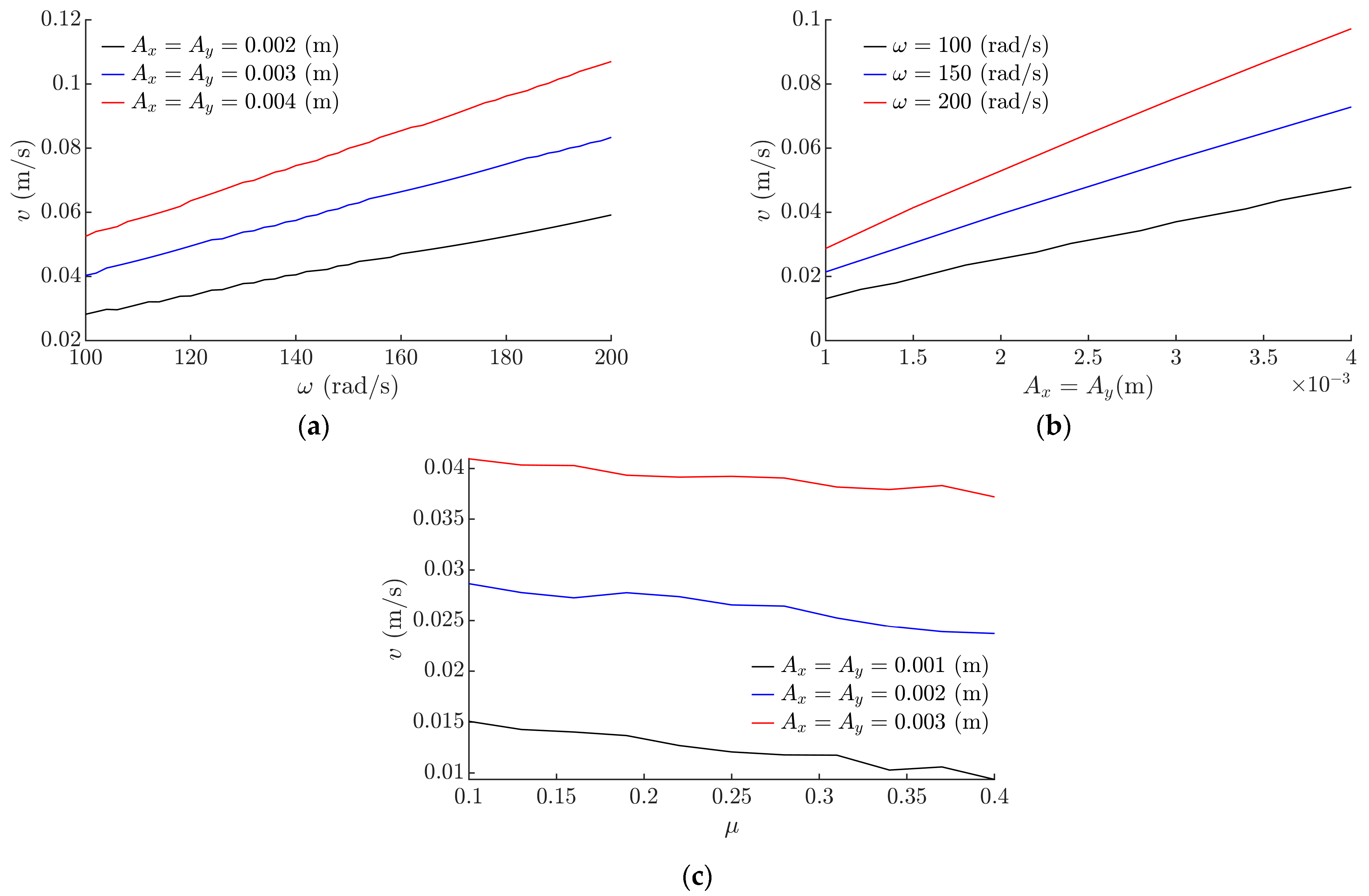
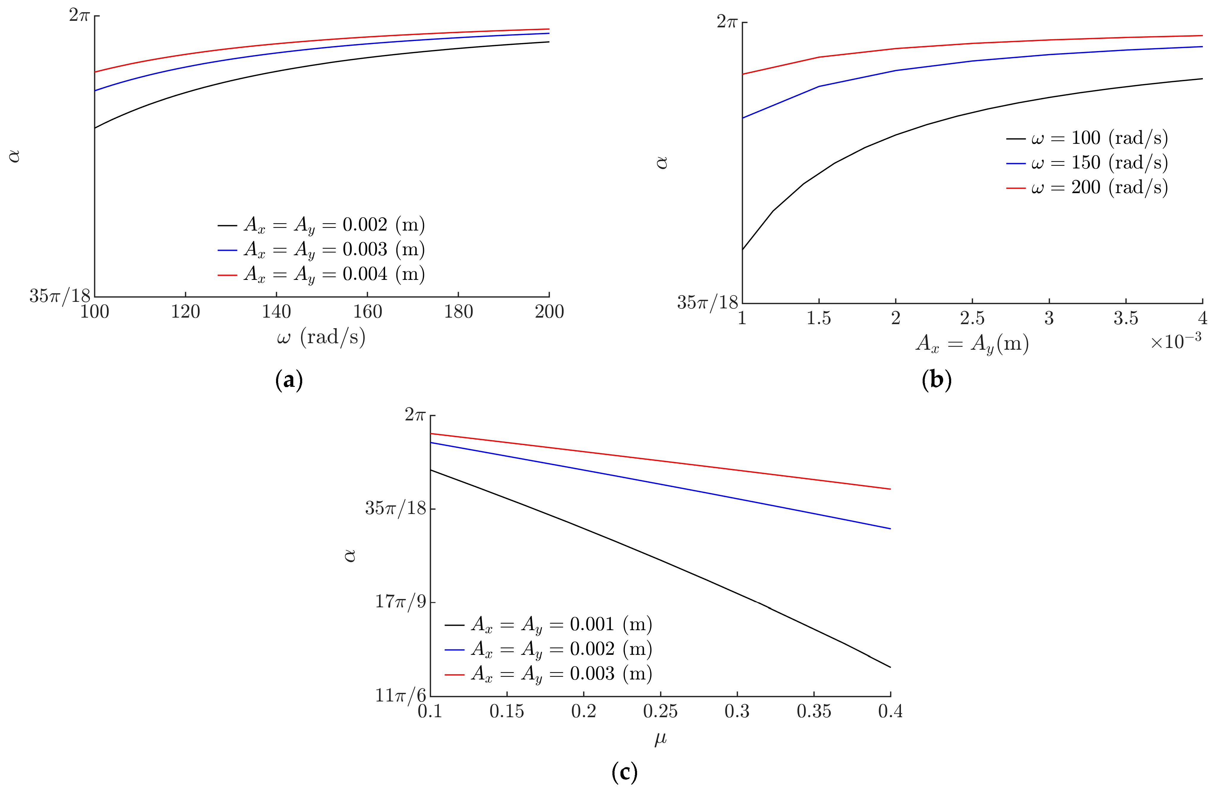
3.1. Motion Characteristics of the Part When the Platform Is Excited in Two Perpendicular Directions by Sinusoidal Waves of the Same Amplitude, and the Phase Shift between the Perpendicular Components Is π/2
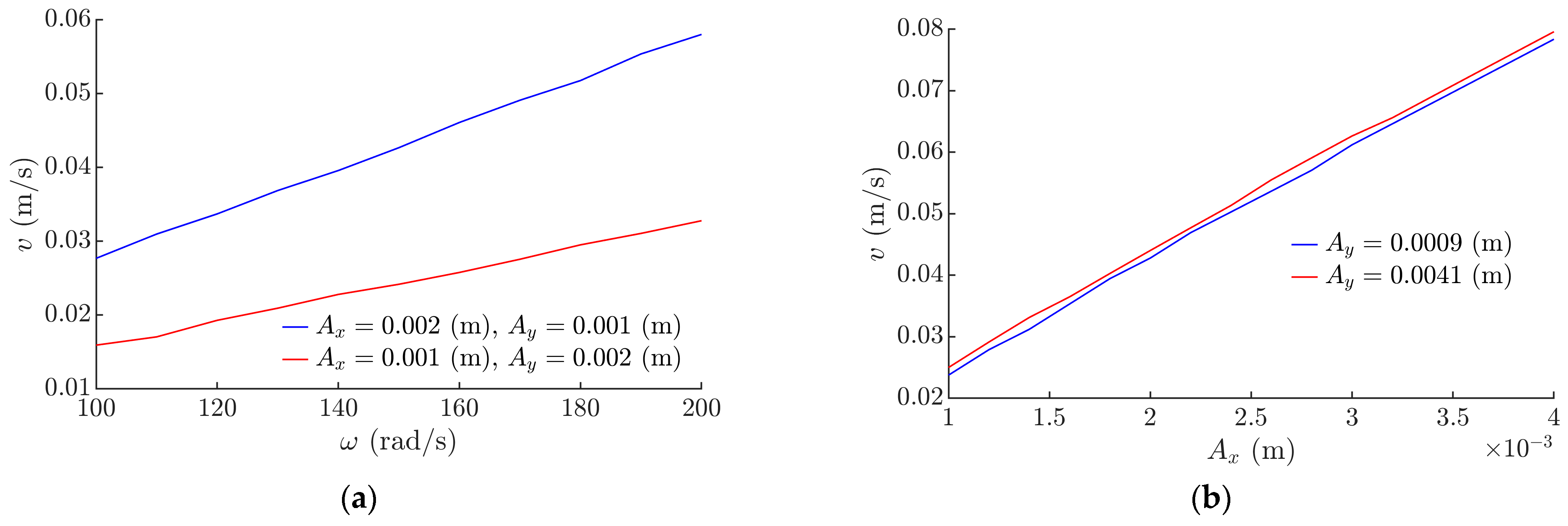
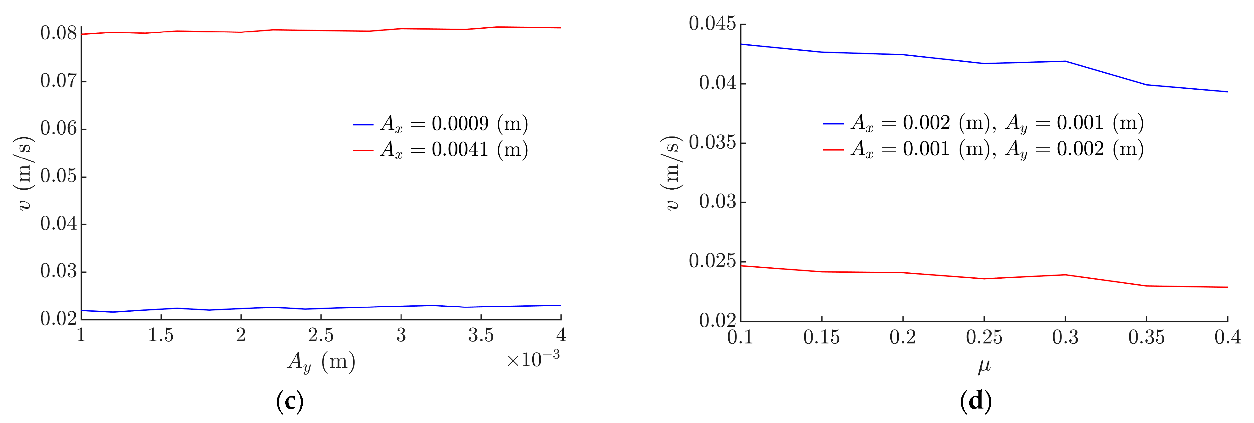
3.2. Motion Characteristics of the Part When the Platform Is Excited in Two Perpendicular Directions by Sinusoidal Waves of Different Amplitudes, and the Phase Shift between the Perpen-dicular Components Is π/2
- 1.
- The sinusoidal wave in the x-direction has a higher amplitude than the sinusoidal wave in the y-direction;
- 2.
- The sinusoidal wave in the y-direction has a higher amplitude than the sinusoidal wave in the x-direction.
3.3. Motion Characteristics of the Part When the Platform Is Excited in Two Perpendicular Directions by Sinusoidal Waves of the Same Amplitude, and the Phase Shift between the Perpendicular Components Varies in the Range of π/10 ≤ ε ˂ 9π/10
4. Conclusions
Author Contributions
Funding
Institutional Review Board Statement
Informed Consent Statement
Data Availability Statement
Conflicts of Interest
References
- Wang, Y.; Qu, D.; Wang, S.; Chen, J.; Qiu, L. Correction of Rotational Eccentricity Based on Model and Microvision in the Wire-Traction Micromanipulation System. Micromachines 2023, 14, 963. [Google Scholar] [CrossRef] [PubMed]
- Alshehhi, F.; Waheed, W.; Al-Ali, A.; Abu-Nada, E.; Alazzam, A. Numerical Modeling Using Immersed Boundary-Lattice Boltzmann Method and Experiments for Particle Manipulation under Standing Surface Acoustic Waves. Micromachines 2023, 14, 366. [Google Scholar] [CrossRef] [PubMed]
- Takosoglu, J.; Janus-Galkiewicz, U.; Galkiewicz, J. A Design of a 2 DoF Planar Parallel Manipulator with an Electro-Pneumatic Servo-Drive—Part 2. Energies 2023, 16, 2970. [Google Scholar] [CrossRef]
- Arena, A.; Ottaviano, E.; Gattulli, V. Dynamics of cable-driven parallel manipulators with variable length vibrating cables. Int. J. Non-Linear Mech. 2023, 151, 104382. [Google Scholar] [CrossRef]
- Šitum, Ž.; Herceg, S.; Bolf, N.; Ujević Andrijić, Ž. Design, Construction and Control of a Manipulator Driven by Pneumatic Artificial Muscles. Sensors 2023, 23, 776. [Google Scholar] [CrossRef] [PubMed]
- Wang, C.; Zhou, Y.; Xie, B.; Xie, J.; Zhang, J. An Underactuated Universal Gripper: Design, Analysis, and Experiment. Energies 2022, 15, 9151. [Google Scholar] [CrossRef]
- Białek, M.; Jędryczka, C. Design and Optimization of a Magnetic Field Exciter for Controlling Magnetorheological Fluid in a Hybrid Soft-Rigid Jaw Gripper. Energies 2023, 16, 2299. [Google Scholar] [CrossRef]
- Ragulskis, K.; Spruogis, B.; Bogdevičius, M.; Matuliauskas, A.; Mištinas, V.; Ragulskis, L. Mechanical systems of precise robots with vibrodrives, in which the direction of the exciting force coincides with the line of relative motion of the system. Mechanika 2021, 27, 408–414. [Google Scholar] [CrossRef]
- Liu, H.; Gao, G.; Lu, S.; Hung, Y. A novel LCOT control strategy for self-driving electric mobile robots. Energies 2022, 15, 9178. [Google Scholar] [CrossRef]
- Taesi, C.; Aggogeri, F.; Pellegrini, N. COBOT Applications—Recent Advances and Challenges. Robotics 2023, 12, 79. [Google Scholar] [CrossRef]
- Kilikevicius, S.; Baksys, B. Dynamic analysis of vibratory insertion process. Assem. Autom. 2011, 31, 275–283. [Google Scholar] [CrossRef]
- Zhang, Z.; Chen, G.; Fan, W.; Yan, W.; Kong, L.; Wang, H. A stiffness variable passive compliance device with reconfigurable elastic inner skeleton and origami shell. Chin. J. Mech. Eng. 2020, 33, 75. [Google Scholar] [CrossRef]
- Shuai, W.; Gao, Y.; Wu, P.; Cui, G.; Chen, X. Sample-Based Passively Compliant Manipulation for Senserless Contact-Rich Scenarios with Uncertainties. In Proceedings of the 2023 9th International Conference on Electrical Engineering, Control and Robotics (EECR), Wuhan, China, 24–26 February 2023; IEEE: Piscataway, NJ, USA, 2023; pp. 16–24. [Google Scholar]
- Ahn, K.; Na, M.; Song, J. Robotic assembly strategy via reinforcement learning based on force and visual information. Robot. Auton. Syst. 2023, 164, 104399. [Google Scholar] [CrossRef]
- Ortega-Aranda, D.; Jimenez-Vielma, J.F.; Saha, B.N.; Lopez-Juarez, I. Dual-arm peg-in-hole assembly using DNN with double force/torque sensor. Appl. Sci. 2021, 11, 6970. [Google Scholar] [CrossRef]
- Nigro, M.; Sileo, M.; Pierri, F.; Bloisi, D.D.; Caccavale, F. Assembly task execution using visual 3D surface reconstruction: An integrated approach to parts mating. Robot. Comput. Integr. Manuf. 2023, 81, 102519. [Google Scholar] [CrossRef]
- Peng, S.; Yu, M.; Cheng, X.; Wang, P. Bilateral Teleoperation System with Integrated Position/Force Impedance Control for Assembly Tasks. Appl. Sci. 2023, 13, 2568. [Google Scholar] [CrossRef]
- Li, Y. Hybrid control approach to the peg-in hole problem. IEEE Robot. Autom. Mag. 1997, 4, 52–60. [Google Scholar] [CrossRef]
- Ghosh, P.K.; Sundaravadivel, P. Stretchable Sensors for Soft Robotic Grippers in Edge-Intelligent IoT Applications. Sensors 2023, 23, 4039. [Google Scholar] [CrossRef]
- Xu, D.; Hu, B.; Zheng, G.; Wang, J.; Li, C.; Zhao, Y.; Yan, Z.; Jiao, Z.; Wu, Y.; Wang, M. Sandwich-like flexible tactile sensor based on bioinspired honeycomb dielectric layer for three-axis force detection and robotic application. J. Mater. Sci. Mater. Electron. 2023, 34, 942. [Google Scholar] [CrossRef]
- Tanabe, K.; Shiota, M.; Kusui, E.; Iida, Y.; Kusama, H.; Kinoshita, R.; Tsukui, Y.; Minegishi, R.; Sunohara, Y.; Fuchiwaki, O. Precise Position Control of Holonomic Inchworm Robot Using Four Optical Encoders. Micromachines 2023, 14, 375. [Google Scholar] [CrossRef]
- Dekker, I.; Kellens, K.; Demeester, E. Design and Evaluation of an Intuitive Haptic Teleoperation Control System for 6-DoF Industrial Manipulators. Robotics 2023, 12, 54. [Google Scholar] [CrossRef]
- Zhu, M.; Zhang, G.; Zhang, L.; Han, W.; Shi, Z.; Lv, X. Object Segmentation by Spraying Robot Based on Multi-Layer Perceptron. Energies 2022, 16, 232. [Google Scholar] [CrossRef]
- Zhou, Y.; Wang, X.; Zhang, L. Research on Assembly Method of Threaded Fasteners Based on Visual and Force Information. Processes 2023, 11, 1770. [Google Scholar] [CrossRef]
- Nagy, M.; Lăzăroiu, G.; Valaskova, K. Machine Intelligence and Autonomous Robotic Technologies in the Corporate Context of SMEs: Deep Learning and Virtual Simulation Algorithms, Cyber-Physical Production Networks, and Industry 4.0-Based Manufacturing Systems. Appl. Sci. 2023, 13, 1681. [Google Scholar] [CrossRef]
- Benotsmane, R.; Kovács, G. Optimization of energy consumption of industrial robots using classical PID and MPC controllers. Energies 2023, 16, 3499. [Google Scholar] [CrossRef]
- Klemiato, M.; Czubak, P. Control of the transport direction and velocity of the two-way reversible vibratory conveyor. Arch. Appl. Mech. 2019, 89, 1359–1373. [Google Scholar] [CrossRef]
- Vrublevskyi, I. Vibratory conveying by harmonic longitudinal and polyharmonic normal vibrations of inclined conveying track. J. Vib. Acoust. 2022, 144, 011004. [Google Scholar] [CrossRef]
- Gurskyi, V.; Korendiy, V.; Krot, P.; Zimroz, R.; Kachur, O.; Maherus, N. On the Dynamics of an Enhanced Coaxial Inertial Exciter for Vibratory Machines. Machines 2023, 11, 97. [Google Scholar] [CrossRef]
- Gursky, V.; Krot, P.; Korendiy, V.; Zimroz, R. Dynamic Analysis of an Enhanced Multi-Frequency Inertial Exciter for Industrial Vibrating Machines. Machines 2022, 10, 130. [Google Scholar] [CrossRef]
- Żmuda, W.; Czubak, P. Investigations of the Transport Possibilities of a New Vibratory Conveyor Equipped with a single Electrovibrator. Transp. Probl. 2022, 17, 127–136. [Google Scholar] [CrossRef]
- Schiller, S.; Perchtold, D.; Steiner, W. Nonlinear and chaotic dynamics of a vibratory conveying system. Nonlinear Dyn. 2023, 111, 9799–9814. [Google Scholar] [CrossRef]
- Okabe, S.; Kamiya, Y.; Tsujikado, K.; Yokoyama, Y. Vibratory feeding by nonsinusoidal vibration—Optimum wave form. J. Vib. Acoust. 1985, 107, 188–195. [Google Scholar] [CrossRef]
- Frei, P.U.; Wiesendanger, M.; Büchi, R.; Ruf, L. Simultaneous planar transport of multiple objects on individual trajectories using friction forces. In Distributed Manipulation; Böhringer, K.F., Choset, H., Eds.; Springer: Boston, MA, USA, 2000; pp. 49–64. [Google Scholar] [CrossRef]
- Nath, J.; Das, S.; Vishwakarma, A.; DasGupta, A. Directed transport of a particle on a horizontal surface under asymmetric vibrations. Phys. D Nonlinear Phenom. 2022, 440, 133452. [Google Scholar] [CrossRef]
- Reznik, D.; Canny, J.; Goldberg, K. Analysis of part motion on a longitudinally vibrating plate. In Proceedings of the 1997 IEEE/RSJ International Conference on Intelligent Robot and Systems, Grenoble, France, 11 September 1997; IEEE: Piscataway, NJ, USA, 1997; pp. 421–427. [Google Scholar] [CrossRef]
- Mayyas, M. Parallel Manipulation Based on Stick-Slip Motion of Vibrating Platform. Robotics 2020, 9, 86. [Google Scholar] [CrossRef]
- Mayyas, M. Modeling and analysis of vibratory feeder system based on robust stick–slip motion. J. Vib. Control. 2021, 28, 2301–2309. [Google Scholar] [CrossRef]
- Viswarupachari, C.; DasGupta, A.; Pratik Khastgir, S. Vibration induced directed transport of particles. J. Vib. Acoust. 2012, 134, 051005. [Google Scholar] [CrossRef]
- Umbanhowar, P.; Vose, T.H.; Mitani, A.; Hirai, S.; Lynch, K.M. The effect of anisotropic friction on vibratory velocity fields. In Proceedings of the 2012 IEEE International Conference on Robotics and Automation, St. Paul, MN, USA, 14–19 May 2012; IEEE: Piscataway, NJ, USA, 2012; pp. 2584–2591. [Google Scholar] [CrossRef]
- Mitani, A.; Matsuo, Y. Feeding of microparts along an asymmetric surface using horizontal and symmetric vibrations—Development of asymmetric surfaces using anisotropic etching process of single-crystal silicon. In Proceedings of the 2011 IEEE International Conference on Robotics and Biomimetics, Karon Beach, Thailand, 7–11 December 2011; IEEE: Piscataway, NJ, USA, 2011; pp. 795–800. [Google Scholar] [CrossRef]
- Le, P.H.; Dinh, T.X.; Mitani, A.; Hirai, S. A study on the motion of micro-parts on a saw-tooth surface by the PTV method. J. Dyn. Control Syst. 2012, 6, 73–80. [Google Scholar] [CrossRef]
- Le, P.H.; Mitani, A.; Xuan, T.; Hirai, S. Feed and align microparts on symmetrically vibrating saw-tooth surface. In Proceedings of the 11th World Congress on Intelligent Control and Automation, Shenyang, China, 29 June–4 July 2014; IEEE: Piscataway, NJ, USA, 2014; pp. 5282–5286. [Google Scholar] [CrossRef]
- Chen, H.; Jiang, S.; Liu, R.; Zhang, W. Particle Directional Conveyance under Longitudinal Vibration by considering the Trough Surface Texture: Numerical Simulation Based on the Discrete Element Method. Shock. Vibrat. 2018, 2018, 8260462. [Google Scholar] [CrossRef]
- Kilikevičius, S.; Fedaravičius, A. Vibrational Transportation on a Platform Subjected to Sinusoidal Displacement Cycles Employing Dry Friction Control. Sensors 2021, 21, 7280. [Google Scholar] [CrossRef]
- Kilikevičius, S.; Liutkauskienė, K.; Uldinskas, E.; El Banna, R.; Fedaravičius, A. Omnidirectional Manipulation of Microparticles on a Platform Subjected to Circular Motion Applying Dynamic Dry Friction Control. Micromachines 2022, 13, 711. [Google Scholar] [CrossRef]


Disclaimer/Publisher’s Note: The statements, opinions and data contained in all publications are solely those of the individual author(s) and contributor(s) and not of MDPI and/or the editor(s). MDPI and/or the editor(s) disclaim responsibility for any injury to people or property resulting from any ideas, methods, instructions or products referred to in the content. |
© 2023 by the authors. Licensee MDPI, Basel, Switzerland. This article is an open access article distributed under the terms and conditions of the Creative Commons Attribution (CC BY) license (https://creativecommons.org/licenses/by/4.0/).
Share and Cite
Kilikevičius, S.; Liutkauskienė, K.; Česnavičius, R.; Keršys, A.; Makaras, R. Investigation of the Motion Characteristics of Parts on a Platform Subjected to Planar Oscillations. Appl. Sci. 2023, 13, 9576. https://doi.org/10.3390/app13179576
Kilikevičius S, Liutkauskienė K, Česnavičius R, Keršys A, Makaras R. Investigation of the Motion Characteristics of Parts on a Platform Subjected to Planar Oscillations. Applied Sciences. 2023; 13(17):9576. https://doi.org/10.3390/app13179576
Chicago/Turabian StyleKilikevičius, Sigitas, Kristina Liutkauskienė, Ramūnas Česnavičius, Artūras Keršys, and Rolandas Makaras. 2023. "Investigation of the Motion Characteristics of Parts on a Platform Subjected to Planar Oscillations" Applied Sciences 13, no. 17: 9576. https://doi.org/10.3390/app13179576
APA StyleKilikevičius, S., Liutkauskienė, K., Česnavičius, R., Keršys, A., & Makaras, R. (2023). Investigation of the Motion Characteristics of Parts on a Platform Subjected to Planar Oscillations. Applied Sciences, 13(17), 9576. https://doi.org/10.3390/app13179576