1. Introduction
Over the past few decades, 5G has become a topic that people are discussing and interested in. As 4G systems and technologies mature, the improvements people can make and the spectrum people can choose on 4G are becoming less. However, with the advances of video streaming media and mobile phones, wireless data will increase rapidly, and data explosion will be produced. Evidently, 4G networks cannot meet the demand which is brought by immense numbers of data. In addition to the huge number of data, the number of devices and data transfer rates will also show exponential growth. This requires engineers to come up with new directions, of which super-densification, millimeter wave, and multiple input multiple output (MIMO) are the most anticipated directions [
1,
2]. The purpose of chasing extreme densification is to enhance the area spectral efficiency, which can accommodate more active nodes in a smaller area. Attaining this goal will require making smaller cells [
3,
4]. The first generation of the cells, which have the size of hundreds of square kilometers, appeared in the early 1980s. After several iterations, the cell sizes are now down to a few hundred meters. The reduction in cell size allows the reuse of the spectrum, thereby reducing the number of users per base station (BS). Therefore, it is to be expected that the cell size will be further reduced. The progress of MIMO can increase spectral efficiency, as well. MIMO represents the spatial dimension of the communication. When multi-antennas are used in BSs and mobile devices, the spatial characteristics will come out. Since the late 1990s, MIMO technology has been widely studied, and it was introduced into the WiFi system in 2006 and used to build 3G communication systems [
5,
6]. MIMO has been an inherent component when long-term evolution becomes mature. There are at least two antennas in a mobile device, and up to eight antennas per BS section. In [
7], the effect of increasing the number of antennas is described in detail, and it has three significant advantages. Firstly, spectral efficiency can be enhanced enormously [
8]. Secondly, channel responses can become smooth on account of the large spatial diversity. At last, due to the quasiorthogonal character between each BS, simple structures can be used to transmit and receive signals.
However, regardless of the development of densification and MIMO, a wider band is required [
9]. At present, the microwave frequency band has been almost completely occupied. So, in order to use more new bands, enhancing the frequency and developing millimeter wave is one direction. There are a lot of free spectrums in the millimeter wave band, and there is also some free spectrum in the 20–30 GHz range. However, millimeter wave bands are limited due to high path loss, atmospheric absorption, and high equipment costs in the past, and the focus has been on WiFi and fixed wireless bands, such as 28 GHz, 38 GHz, 71–76 GHz, and 81–86 GHz. However, as semiconductors mature, the cost and power consumption of building millimeter wave systems are falling rapidly. Other obstacles are also thought to be surmountable [
10,
11,
12]. The millimeter wave spectrum can meet the bandwidth requirements for 5G development, as well Therefore, the millimeter wave is an important direction for the development of communication systems.
As a key component of a communication system, an antenna’s performance is closely related to the whole communication system. Therefore, it is important to propose different millimeter wave antennas to meet different demands. With the development of millimeter wave antennas, a variety of antennas with different performance have been published, such as the multiband antenna, dual-frequency antenna, dual-polarized antenna, circularly polarized antenna, and so on. The dual-polarized antenna is one of the key technologies in wireless communication. Using a dual-polarized antenna can realize polarization diversity and improve the capacity and reliability of a wireless communication link. The dual-polarized antenna is realized by feeding two ports of the same antenna to excite two orthogonal polarization modes. At present, many dual-polarized antennas have been published, such as magnetoelectric dipole (ME-dipole) antennas [
13,
14,
15], horn antennas [
16,
17], substrate-integrated waveguide (SIW) antennas [
18,
19], and patch antennas [
20,
21]. In [
13], a wideband dual-polarized antenna in a millimeter wave band is investigated. The ME-dipole is composed of four patches and fed by two pairs of orthogonal T-shaped probes. A port is connected with a pair of probes by a T-shaped power divider; thus, dual-polarized performance is realized when the different port is excited. The antenna achieves an overlapped impedance bandwidth of over 50% and isolation higher than 17.8 dB. An 8 × 8 dual-polarized ME-dipole antenna array is published in [
14]. The antenna element employs the metallic pillars and cavity as ME-dipoles. A cross slots is used to excite two polarizations. Finally, the antenna array maintains an impedance bandwidth from 34.7 to 39.7 GHz (13.4%), as well as a mutual coupling of below 27 dB in the operating band. In [
15], a dual-polarized ME-dipole antenna fed by a fork-shaped microstrip line is present. The antenna element is formed with four patches and two cross slots. Then, a 1 × 4 antenna array is designed, fabricated, and tested. The antenna array has an overlapped −10 dB impedance bandwidth in 28–33.5 GHz. In [
16], a L-shaped horn antenna is proposed. The antenna is filled with dielectric material and fed by two orthogonal waveguides. A wide impedance bandwidth is obtained within 34–40 GHz, and the mutual coupling of the two ports is below 15 dB. In [
18], a dual-polarized SIW phased array is investigated. By curving slots on the SIW cavity surface, the antenna can radiate electromagnetic waves. Dual polarization is realized by a differentially fed SIW cavity and a microstrip line. A 1 × 4 antenna array is then constructed. The antenna array obtains an impedance bandwidth from 25.8 to 28.8 GHz (11.0%). The isolation is higher than 31.5 dB. A substrate-integrated mode-based end-fire antenna is presented in [
19]. A sandwich structure, which is composed of two metal blocks with an open-ended slot, is designed to radiate electromagnetic waves. And the horizontal polarization (HP) is based on the transverse electromagnetic (TEM) mode; in addition, the vertical polarization (VP) is excited by TE
10 mode. The antenna achieves a wide impedance bandwidth of 24.8–32.5 GHz (26.9%). A high isolation between the two polarizations of over 36 dB is also realized. A dual-polarized Spoof-surface-plasmon-polaritons (SSPP) fed patch antenna array is proposed in [
20]. Two orthogonal SSPPs are simply connected to a square patch. Therefore, the TM
01 mode and TM
10 mode can be excited simultaneously, and the dual polarization is obtained. Measurement results shows that the antenna has the −10 dB impedance bandwidth of 13.7% and the isolation is more than 15 dB. In [
21], a dual-band dual-polarized patch antenna is studied. The antenna uses two pairs of stacked ring patches to obtain dual-band performance. The feeding structure is formed by two striplines coupled with orthogonal H-slots, which makes the antenna gain the dual-polarization in two bands.
There are still lots of way to promote the performance of dual-polarized antennas. However, in order to chase wide impedance matching, the configuration of antennas becomes more complex. It also led to an increase in antenna size and a decrease in radiation efficiency. To maintain wideband performance and simple structure, horn antennas can be seen as a potential candidate. However, horn antennas are always designed in microwave bands with an all-metal configuration. They are not suitable in millimeter wave bands because of their bulky size and difficulty to integrate. To solve this problem, horn antennas in the millimeter wave band can be designed using substrate-integrated waveguide technology. The substrate-integrated waveguide technique can be used to confine the electromagnetic energy in the waveguide cavity by replacing the metal wall with a uniform array of metal columns. By using substrate-integrated waveguide technology, horn antennas can gain the advantages of easy integration and a low profile [
22,
23,
24]. In [
22], a dual-polarized end-fire antenna array is achieved by integrating dipoles on the SIW horns. A pair of dipoles produces HP, while SIW horn antennas radiate VP. The dual-polarized antenna can cover the 5G bands of N257 and N258 and achieve a maximum gain of 6.5 dBi for both polarizations. The isolation between two ports is higher than 15 dB. In [
23], a dual-polarized antenna element is designed by combining an HP dipole and a VP
H-plane horn antenna, and then a 1 × 4 antenna array is designed and fabricated. The impedance bandwidth where the |
S11| < −10 dB for both polarizations is 24.4–29.5 GHz. In the operating band, the maximum gain is 16 dBi, with an isolation higher than 20 dB. An
E-band SIW dual-polarized horn antenna with an orthomode transducer is proposed in [
24]. An SIW section is adopted to excite the TE
10 mode and produce VP. The quasi-TEM mode is excited by a quasi-coaxial stripline, and HP is generated. Its impedance bandwidth lower than −10 dB is from 83 to 87 GHz and achieves a maximum gain of 14 dBi for HP and 15.2 dBi for VP. The isolation between two polarizations is higher than 25 dB. In the abovementioned designs, in order to realize the dual polarization, the SIW horn antennas are always combined with complex feeding structures. This will increase the difficulty of fabrication and increase the antenna size. The isolation between two ports is also not good enough. Therefore, it is sufficient to provide a wide-band dual-polarized antenna with a simple radiation configuration and feeding structures as well as a good isolation performance.
In this paper, a low-profile dual-polarized antenna is proposed by integrating a traditional Vivaldi antenna on the surface of the SIW
H-plane horn antenna to realize dual polarizations. The Vivaldi antenna radiates VP electromagnetic waves, and the horn antenna radiates HP electromagnetic waves. A dielectric lens is loaded at the aperture of the horn antenna for better impedance matching and enhancing directivity. To improve the isolation between two ports, two different feeding structures are utilized to excite different ports. The proposed dual-polarized antenna is fabricated and measured, which achieves a −10 dB impedance bandwidth from 20.94 GHz to 25.50 GHz for both polarizations. In the operating band, the antenna achieves a maximum gain of 8.2 dBi. The proposed dual-polarized antenna is suitable for 5G mm-wave communication. In
Section 2, the design procedure of the dual-polarized antenna is illustrated, including the simulation results of the SIW horn antenna and Vivaldi antenna. In
Section 3, parametric study is presented which is used to verify the influence of different parameters on antenna performance. The dual-polarized antenna is fabricated and tested. A comparison of the antenna simulation and test results as well as a comparison of this antenna with other published antennas are given in
Section 4.
Section 5 draws a conclusion of this work.
2. Design of Dual-Polarized Antenna
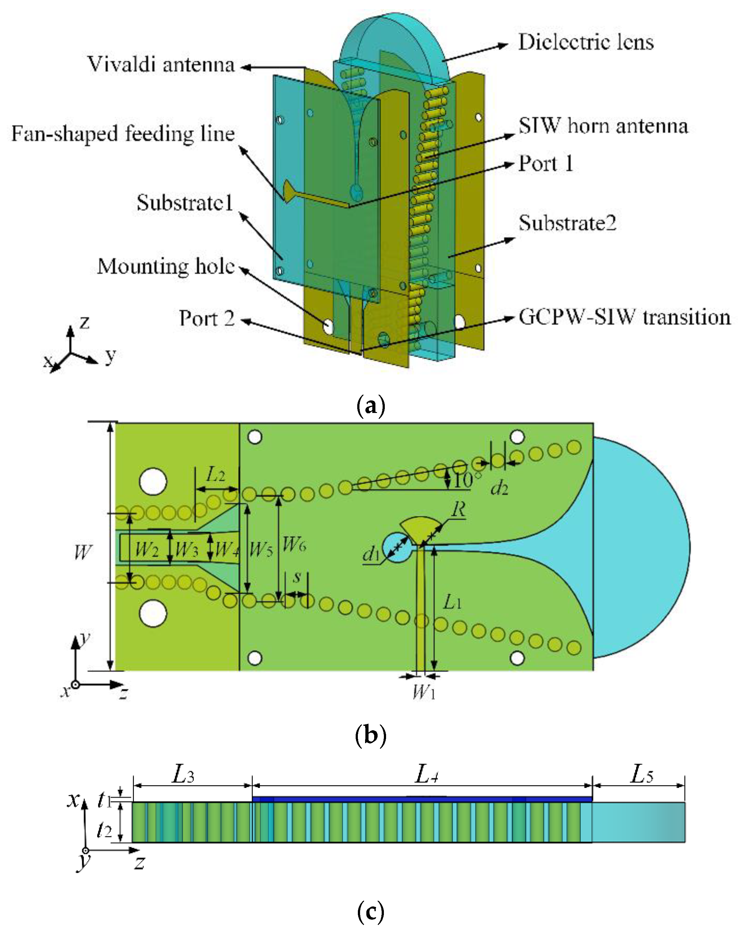
The geometry of the dual-polarization antenna is displayed in
Figure 1. The antenna is composed of an SIW
H−plane horn antenna, a Vivaldi antenna, and a dielectric lens. Two Arlon AD430 substrates (εr = 4.3, tanδ = 0.003) and three copper layers are used to construct the antenna. These structures are assembled by screws. The dual−polarized antenna was modeled in CST studio 2020.
The Vivaldi antenna is etched on both surfaces of the horn antenna and fed through a microstrip line with a fan−shaped terminal. The fan−shaped feeding line is located at the top of Substrate 1 as port 1. The horn antenna is located on the lower dielectric substrate and fed by a grounded coplanar waveguide (GCPW) to an SIW transition line as port 2. A lens is loaded at the aperture of the horn antenna for better impedance matching and higher directivity.
The structure of the
H−plane horn antenna is shown in
Figure 2. To ensure that the horn antenna only transmits the TE
10 mode throughout the operating band, the width
W2 and
W6 and thickness
t2 of the antenna are calculated and designed according to [
25,
26]. Since the thickness of the antenna is much smaller than the operating wavelength, the beamwidth of the
E−plane radiation pattern is wide, and the impedance matching is poor. To solve these problems, a dielectric lens is loaded at the aperture of the horn antenna as a dielectric guided structure in the
E−plane. The simulated impedance matching is shown in
Figure 3. After adding the dielectric lens, the impedance matching is obviously improved, which covers the bandwidths of 25.31–26.71 GHz. The comparison of the radiation patterns with and without the lens is plotted in
Figure 4. With the loading of an appropriate−size lens, the radiated beamwidth of the horn antenna is significantly narrowed. Consequently, the directivity of the horn antenna is improved from 5.8 dBi to 9.0 dBi at 26 GHz.
In order to realize the dual polarization and maintain wide−band performance, a typical Vivaldi antenna that provides VP is designed on the basis of the existing
H−plane horn antenna. By adding a Vivaldi antenna, the size of the whole antenna is hardly changed but obtains VP. The Vivaldi antenna is fed by a fan−shaped microstrip line, as shown in
Figure 5, and radiates VP electromagnetic waves. After optimizing the size of the Vivaldi antenna, the parameters of the final antenna design are shown in
Table 1. The simulated impedance matching of the Vivaldi antenna is shown in
Figure 6, which has a simulated −10 dB impedance bandwidth of 23.25% (21.10–26.65 GHz). The bandwidth basically covers the impedance bandwidth of the SIW horn antenna.
Figure 7 shows the simulated results of the radiation patterns of the antenna at 22.25 GHz, where the peak gain of the Vivaldi antenna is 8.0 dBi.
3. Parametric Analysis of The Antenna
In this section, a parametric study is performed to clarify the effect of some key parameters on an antenna’s impedance matching. When one parameter of the antenna is changed, the other parameters remain the same. The effects of the radius of the Vivaldi antenna fan−shaped feed R, the thickness of the upper substrate t1, and the width of the horn antenna W6 are analyzed. These three parameters significantly affect the antenna’s impedance matching.
As shown in
Figure 8, with the increase in fan−shaped feed radius
R, the impedance matching becomes worse at high frequencies. The radius of the fan−shaped structure is about a quarter wavelength of the center frequency point of the antenna. Therefore, with the increase in fan−shaped feed radius
R, the operating band of the antenna is shifted to the lower frequency, and the impedance matching at high frequency becomes worse. In order to realize the best performance, the final fan−shaped feed radius
R is determined to be 2.3 mm. The thickness
t1 also affects the impedance matching of the Vivaldi antenna and almost has no effect on the horn antenna. The reflection coefficient of the Vivaldi antenna as
t1 varies is shown in
Figure 9. As the
t1 increases from 0.2 mm to 0.4 mm, the impedance matching of the antenna is improved at 22.5 GHz but becomes worse at 21 GHz and 23.5 GHz. When
t1 is 0.3 mm, the Vivaldi antenna has the best impedance matching at 26 GHz, and both polarizations obtain a wide bandwidth at both polarizations. The final thickness of the Substrate 1 is determined as 0.3 mm.
In order to obtain the widest operating band in the two polarizations, the width of the horn antenna
W6 is analyzed. The reflection coefficient |
S22| of the horn antenna varies with
W6, while the reflection coefficient |
S11| hardly changes. As shown in the
Figure 10 plot, the resonant frequency of the horn antenna shifts towards lower frequencies as
W6 increases from 7.7 mm to 8.1 mm. The resonant mode of the horn antenna is the
TE10 mode. By exciting the
TE10 mode, HP is obtained. With
W6 increases, the frequency corresponding to the
TE10 mode in the horn antenna decreases. Therefore, by changing
W6, the impedance matching of the horn antenna can be optimized independently. Finally, the width
W6 is determined to be 7.9 mm for the best impedance bandwidth. By analyzing the parameters of the proposed antenna, the best impedance matching can be obtained quickly. It is helpful to get the best performance of the antenna.
4. Results and Discussions
The antenna has the dimensions of 39.7 mm × 18 mm × 3.3 mm. To verify the performance of the proposed antenna, a prototype is fabricated and measured. The
S−parameters of the dual−polarized antenna are tested by an Agilent vector network analyzer E8363B, and the radiation pattern is measured in an anechoic chamber. Due to the test equipment limitations, the pattern is only tested from −90° to 90°.
Figure 11 shows the fabricated prototype of the dual−polarized antenna. The simulated and measured results of
S−parameters are shown in
Figure 12. The simulated reflection coefficients of both polarizations are lower than −10 dB in the range of 20.25–26.55 GHz (26.92%), while the measured ones are 20.04–25.5 GHz (23.98). The simulated and measured results have a reasonable agreement.
The measured isolation between the two ports of the antenna is above 36 dB in the operating band, indicating that the antenna has good isolation between the two polarizations. When port 1 of the Vivaldi antenna is excited, the antenna exhibits good directionality at 22.5 GHz, as shown in
Figure 13. The peak simulated gain of the Vivaldi antenna is 8.2 dBi at 22.5 GHz, while the measured gain is 7.0 dBi. Both simulated and measured cross−polarizations are lower than −20 dB. The maximum radiation direction deviates slightly from the normal direction due to the asymmetry of the antenna. When port 2 of the horn antenna is excited, the radiation pattern of the antenna is shown in
Figure 14. It is shown that the horn antenna has the simulated gain of 7.1 dBi and the measured gain of 5.2 dBi. The simulated and measured cross−polarization are both lower than −26 dB. As shown in
Figure 15, the horn antenna also achieves the maximum gain at 22.5 GHz. The dual−polarized antenna has a stable gain in the 20–23.5 GHz range for both polarizations. The difference between simulation results and measurement results may be from the air gap between the two dielectric substrates. Since the antenna is combined with two substrate layers and connected by screws, the air gap will inevitably appear. In addition, since the air gap between the two dielectric substrates is not the same everywhere, this difference is also difficult to verify by simulation results.
To illustrate the advantages of the proposed dual−polarized antenna in detail, the performance of some existing dual−polarized antenna element and antenna array compared with the proposed design is listed in
Table 2. With the exception of ref. [
27], the proposed antenna has a wider overlapped impedance bandwidth than other contrasting antennas. This is thanks to the way one obtains dual polarization, i.e., by integrating two wideband antennas: the horn antenna and the Vivaldi antenna. It is also obvious that the antenna has great isolation between two polarizations. The high isolation of the antenna comes from the use of different feed structures at the two ports. However, some antenna arrays are listed in
Table 2, which makes the comparison of gain unclear. The high gain of the proposed antenna can be seen from the comparison with ref. [
20] and ref. [
27,
28]. The antenna owns high gain since it adopts a dielectric lens to enhance directivity. Additionally, the antenna is designed using SIW technology, which has the advantage of being easy to integrate and having a low profile. Therefore, the proposed antenna is a wideband antenna with high gain and good isolation.


