
Research on Thermal and Heat Insulation Properties of Aerogel Heat-Insulating Reflective Coatings

Abstract
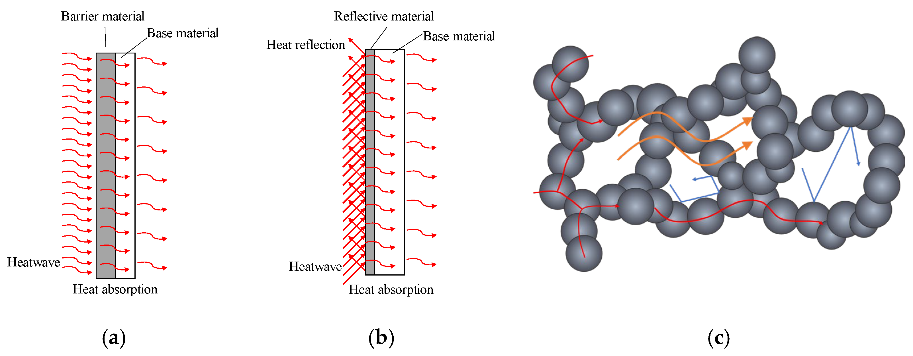
:1. Introduction
2. Experimental Studies
2.1. Specimen Preparation
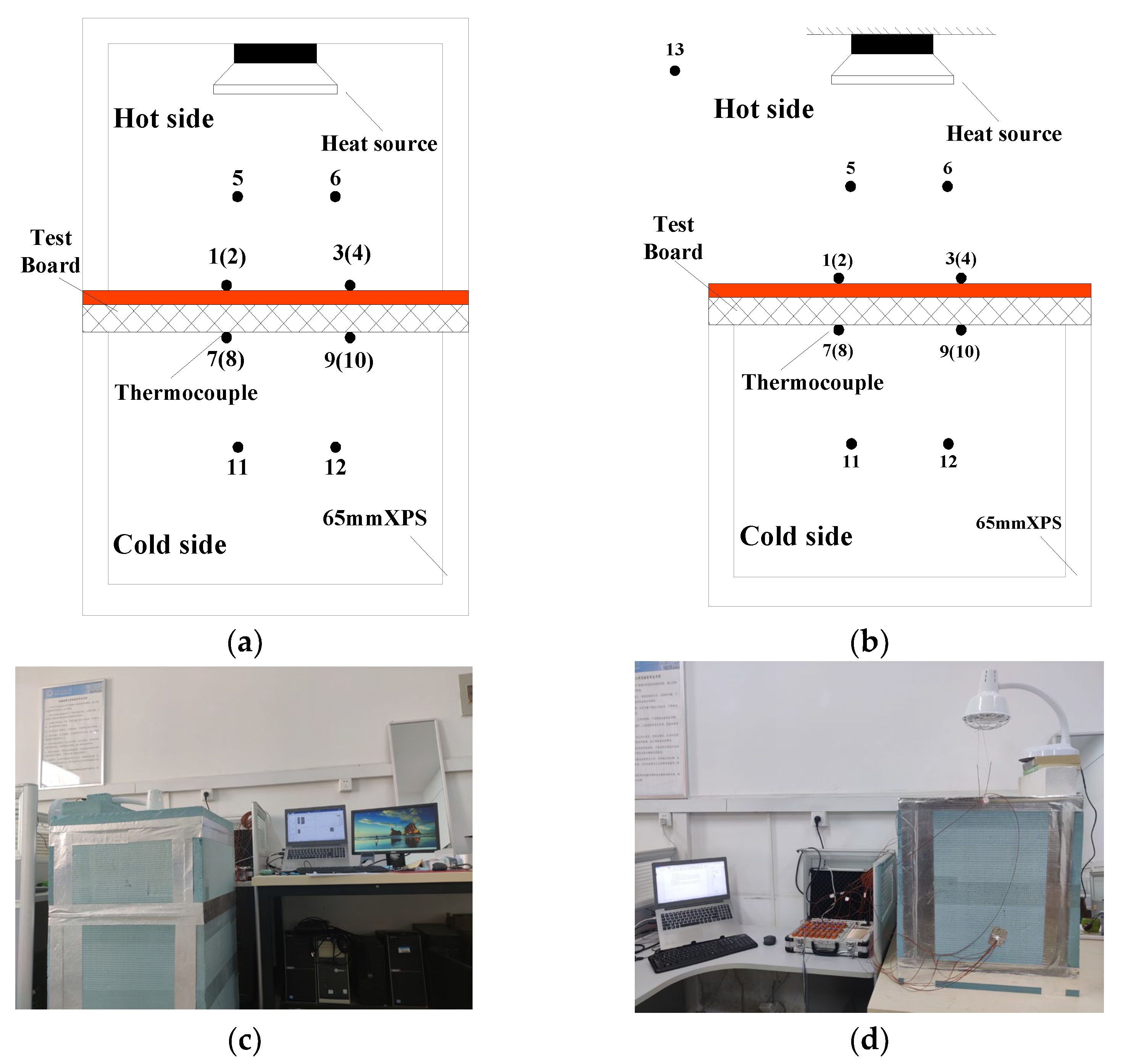
2.2. Test Method
3. Data Analysis
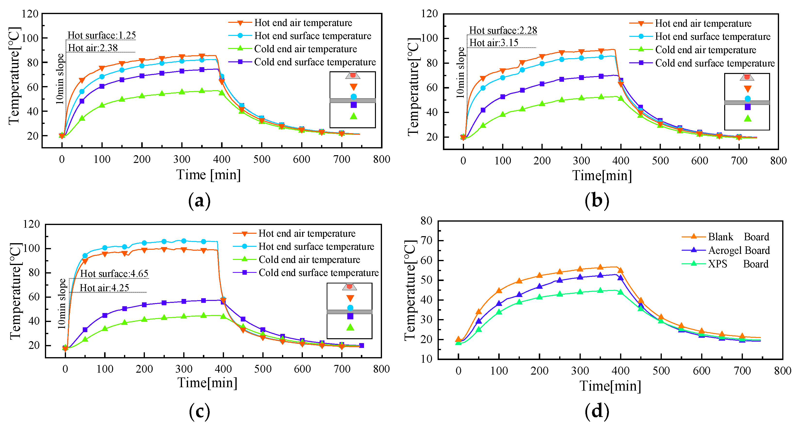
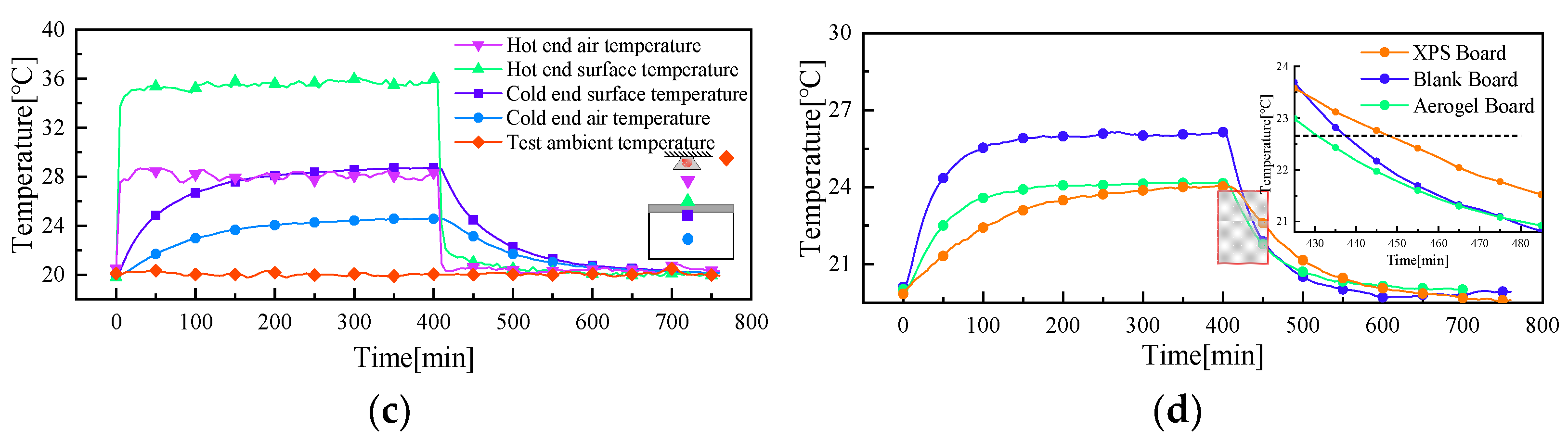
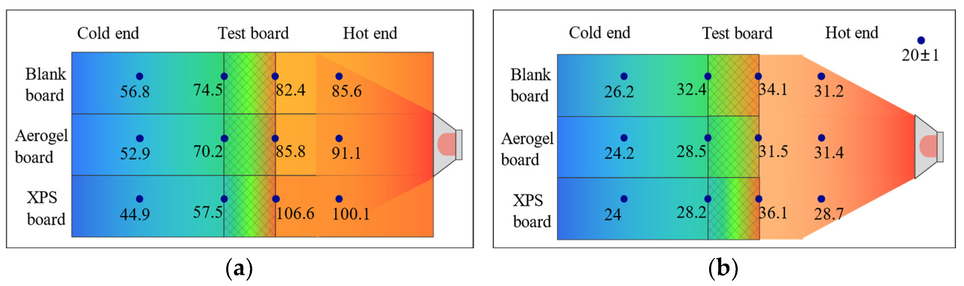
3.1. Temperature of the Measuring Point for Condition 1
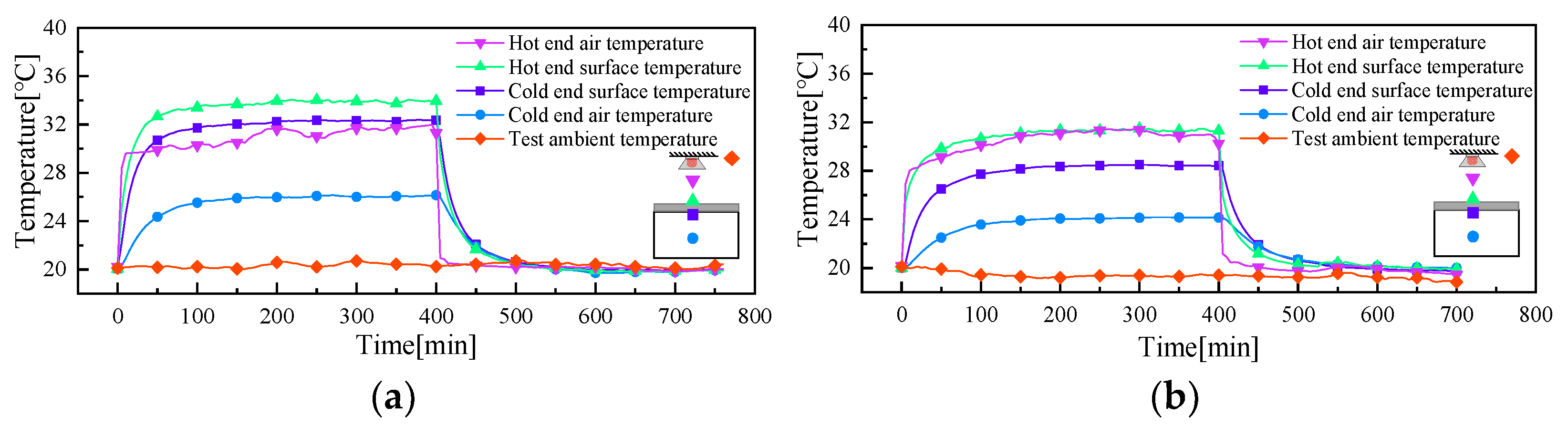
3.2. Temperature of the Measuring Point for Working Condition 2
3.3. Characteristic Data Analysis
4. Theoretical Heat Transfer Calculations
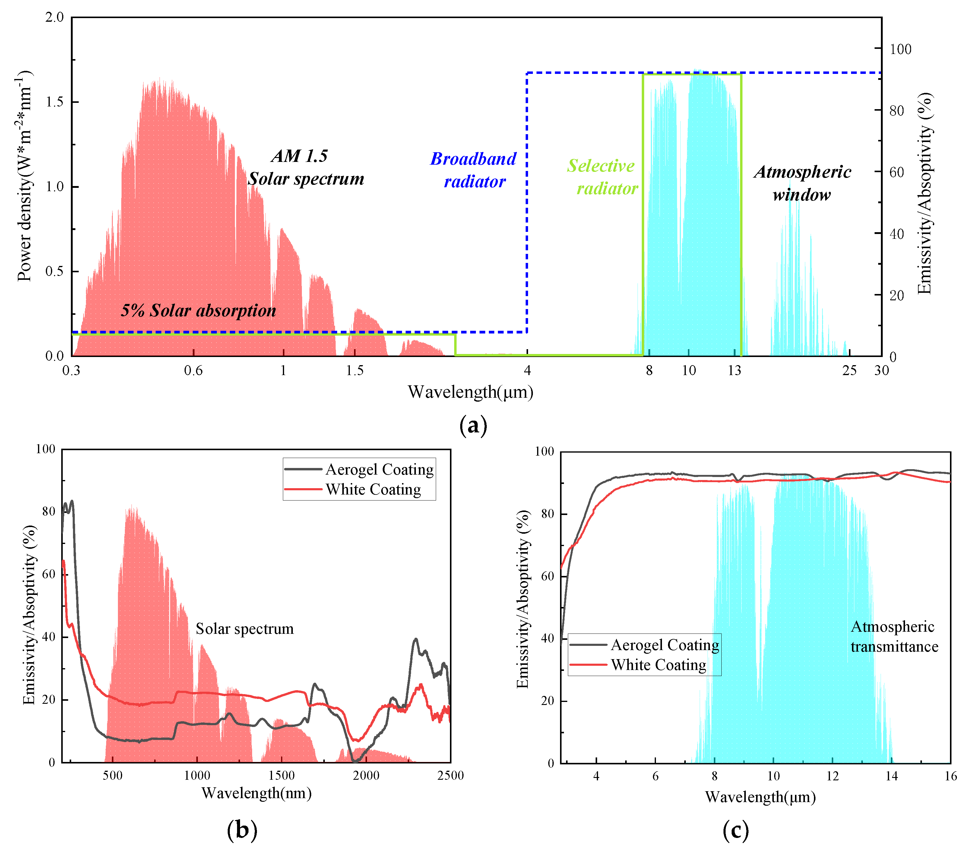
4.1. Calculation of Radiant Heat Transfer
4.2. Calculation of Heat Transfer Barrier
5. Conclusions
Author Contributions
Funding
Institutional Review Board Statement
Informed Consent Statement
Data Availability Statement
Conflicts of Interest
References
- Qian, D.; Li, Y.; Niu, F.; O’Neill, Z. Nationwide savings analysis of energy conservation measures in buildings. Energy Convers. Manag. 2019, 188, 1–18. [Google Scholar]
- Ibrahim, M.; Bianco, L.; Ibrahim, O.; Wurtz, E. Low-emissivity coating coupled with aerogel-based plaster for walls’ internal surface application in buildings: Energy saving potential based on thermal comfort assessment. J. Build. Eng. 2018, 18, 454–466. [Google Scholar]
- Makar, M.; Pravica, L.; Kutija, M. Supercapacitor-Based Energy Storage in Elevators to Improve Energy Efficiency of Buildings. Appl. Sci. 2022, 12, 7184. [Google Scholar]
- Li, C.L.L. Experimental study of the thermal performance of a building wall with vacuum insulation panels and extruded polystyrene foams. Appl. Therm. Eng. Des. Process. Equip. Econ. 2020, 180, 115801. [Google Scholar]
- Malunjkar, G.; McElroy, H.; Coroneo, M.; Ogunniyi, A.O. Improving the quality of rigid polyurethane foam sandwich insulation panels. MRS Adv. 2023, 8, 489–493. [Google Scholar] [CrossRef]
- Vaidya, A.; Uddin, N.; Vaidya, U. Structural characterization of composite structural insulated panels for exterior wall applications. J. Compos. Constr. 2010, 14, 464–469. [Google Scholar] [CrossRef]
- Thai, H.N.; Kawamoto, K.; Nguyen, H.G.; Sakaki, T.; Komatsu, T.; Moldrup, P. Measurements and Modeling of Thermal Conductivity of Recycled Aggregates from Concrete, Clay Brick, and Their Mixtures with Autoclaved Aerated Concrete Grains. Sustainability 2022, 14, 2417. [Google Scholar] [CrossRef]
- Lakatos, Á.; Csík, A. Multiscale Thermal Investigations of Graphite Doped Polystyrene Thermal Insulation. Polymers 2022, 14, 1606. [Google Scholar]
- Vitale, M.; Cascone, S.M. Thermal, Physical and Mechanical Performance of Orange Peel Boards: A New Recycled Material for Building Application. Sustainability 2021, 13, 7945. [Google Scholar]
- Zhang, G.; Wu, H.; Liu, J.; Yang, J.; Huang, H.; Ding, Y.; Xie, L. Dynamic performance and energy efficiency of reflective and insulative composite coating on building exterior wall. Build. Simul. 2022. [Google Scholar] [CrossRef]
- Karim, A.N.; Johansson, P.; Kalagasidis, A.S. Knowledge gaps regarding the hygrothermal and long-term performance of aerogel-based coating mortars. Constr. Build. Mater. 2022, 314, 125602. [Google Scholar]
- Calisesi, M. Aerogel Incorporated Plasters and Mortars the Case Study of Precast Panels. Diploma Thesis, Alma Mater Studiorum—Università di Bologna, Bologna, Italy, 2016. [Google Scholar]
- Ganesamoorthy, R.; Vadivel, V.K.; Kumar, R.; Kushwaha, O.S.; Mamane, H. Aerogels for water treatment: A review. J. Clean. Prod. 2021, 329, 129713. [Google Scholar]
- Buratti, C.; Moretti, E.; Belloni, E.; Agosti, F. Development of Innovative Aerogel Based Plasters: Preliminary Thermal and Acoustic Performance Evaluation. Sustainability 2014, 6, 5839–5852. [Google Scholar]
- Di, Z.; Ma, S.; Wang, H.; Guan, Z.; Lian, B.; Qiu, Y.; Jiang, Y. Modulation of Thermal Insulation and Mechanical Property of Silica Aerogel Thermal Insulation Coatings. Coatings 2022, 12, 1421. [Google Scholar]
- Patricia Fernanda Bergmann, B.; Carmeane, E.; Adilson, S. Lightweight thermal insulating coating mortars with aerogel, EPS, and vermiculite for energy conservation in buildings. Cem. Concr. Compos. 2021, 125, 104283. [Google Scholar] [CrossRef]
- Carnicer, V.; Canas, E.; Orts, M.J.; Sánchez, E. Feasibility of incorporating silica aerogel in atmospheric plasma spraying coatings. Ceram. Int. 2021, 18, 47. [Google Scholar]
- Eunyoung, K.; Kit-Ying, C.; Jie, Y.; Venkatesan, H.; Adegun, M.H.; Zhang, H.; Lee, J.-H.; Shen, X.; Kim, J.K. Engineering anisotropic structures of thermally insulating aerogels with high solar reflectance for energy-efficient cooling applications. J. Mater. Chem. A 2023, 11, 7105–7114. [Google Scholar]
- Wang, J.; Petit, D.; Ren, S. Transparent thermal insulation silica aerogels. Nanoscale Adv. 2020, 2, 5504–5515. [Google Scholar]
- ISO 8990:1994; General Administration of Quality Supervision, Inspection and Quarantine of the People’s Republic of China. Thermal Insulation—Determination of Steady-State Thermal Transmission Properties—Calibrated and Guard Hot Box. China National Standardization Administration: Beijing, China, 1994; p. 24.
- GB 25261-2018; State Administration of Market Administration. Solar Heat Reflecting Insulation Coatings for Buildings. China National Standardization Administration: Beijing, China, 2018; p. 24.
- Yun, T.S.; Jeong, Y.J.; Han, T.S.; Youm, K.S. Evaluation of thermal conductivity for thermally insulated concretes. Energy Build. 2013, 61, 125–132. [Google Scholar] [CrossRef]
- Ropelewski, L.; Neufeld, R.D. Thermal inertia properties of autoclaved aerated concrete. J. Energy Eng. 1999, 125, 59–75. [Google Scholar]
- GB 50176-93; Thermal Design Code for Civil Building. National Standards of the People’s Republic of China: Beijing, China, 2015; pp. A90–A94.
- Zhao, Z.; Yang, X.; Qu, X.; Zheng, J.; Mai, F. Thermal insulation performance evaluation of autoclaved aerated concrete panels and sandwich panels based on temperature fields: Experiments and simulations. Constr. Build. Mater. 2021, 303, 124560. [Google Scholar]
- Fathipour, R.; Hadidi, A. Analytical solution for the study of time lag and decrement factor for building walls in climate of Iran. Energy 2017, 134, 167–180. [Google Scholar]
- Streimikiene, D.; Skulskis, V.; Balezentis, T.; Agnusdei, G.P. Uncertain multi-criteria sustainability assessment of green building insulation materials. Energy Build. 2023, 219, 110021. [Google Scholar]
- Zhao, B.; Hu, M.; Ao, X.; Chen, N.; Pei, G. Radiative cooling: A review of fundamentals, materials, applications, and prospects. Appl. Energy 2019, 236, 489–513. [Google Scholar]
- Xue, X.; Qiu, M.; Li, Y.; Zhang, Q.M.; Li, S.; Yang, Z.; Feng, C.; Zhang, W.; Dai, J.-G.; Lei, D. Creating an Eco-Friendly Building Coating with Smart Subambient Radiative Cooling. Adv. Mater. 2020, 32, 42. [Google Scholar]
- Available online: https://download.csdn.net/download/Diamond4058/16809577 (accessed on 3 April 2023).
- Available online: https://www.gemini.edu/bserving/telescopes-and-sites/sites#Transmission (accessed on 17 December 2022).


| Materials | Thickness mm | Thermal Conductivity W/(m·K) | Manufacturers |
|---|---|---|---|
| Plasterboard | 9.7 | 0.120 | Hefei Youtai Building Materials Co. Hefei, China |
| Aerogel coatings | 1.1 | 0.066 | Laboratory homemade |
| XPS insulation panels | 19 | 0.037 | Nanjing Ogle Energy Saving and Environmental Protection Technology Co. Nanjing, China |
| White coating | 1 | 0.117 | Anhui Xin Peng New Material Co. Anqing, China |
| Test Conditions | Feature Data | Blank Board | Aerogel Board | XPS Board |
|---|---|---|---|---|
| Test Condition 1 | Damping factor | 0.560999743 | 0.469470229 | 0.323897396 |
| Time lag/min | 20 | 25 | 140 | |
| Test Condition 2 | Damping factor | 0.553571429 | 0.368421053 | 0.459770115 |
| Time lag/min | 5 | 40 | 360 |
| K/W | R K/W | W/m2 | ||||
|---|---|---|---|---|---|---|
| Plasterboards | Aerogel Coating | White Coating | XPS | |||
| Blank board | 0.81 | / | 0.10 | / | 0.91 | 10.98 |
| Aerogel board | 0.81 | 0.24 | / | / | 1.05 | 9.55 |
| XPS board | 0.81 | / | / | 5.14 | 5.94 | 1.68 |
Disclaimer/Publisher’s Note: The statements, opinions and data contained in all publications are solely those of the individual author(s) and contributor(s) and not of MDPI and/or the editor(s). MDPI and/or the editor(s) disclaim responsibility for any injury to people or property resulting from any ideas, methods, instructions or products referred to in the content. |
© 2023 by the authors. Licensee MDPI, Basel, Switzerland. This article is an open access article distributed under the terms and conditions of the Creative Commons Attribution (CC BY) license (https://creativecommons.org/licenses/by/4.0/).
Share and Cite
Liu, Y.-L.; Yang, D.-G.; Wang, D.-H.; Liu, X. Research on Thermal and Heat Insulation Properties of Aerogel Heat-Insulating Reflective Coatings. Appl. Sci. 2023, 13, 9700. https://doi.org/10.3390/app13179700
Liu Y-L, Yang D-G, Wang D-H, Liu X. Research on Thermal and Heat Insulation Properties of Aerogel Heat-Insulating Reflective Coatings. Applied Sciences. 2023; 13(17):9700. https://doi.org/10.3390/app13179700
Chicago/Turabian StyleLiu, Yun-Lin, Ding-Guo Yang, Dong-Hua Wang, and Xuan Liu. 2023. "Research on Thermal and Heat Insulation Properties of Aerogel Heat-Insulating Reflective Coatings" Applied Sciences 13, no. 17: 9700. https://doi.org/10.3390/app13179700