
Development and Evaluation of Doppler Ultrasound Training Phantom for Human Vessel Simulation
Abstract
:1. Introduction
2. Materials and Methods
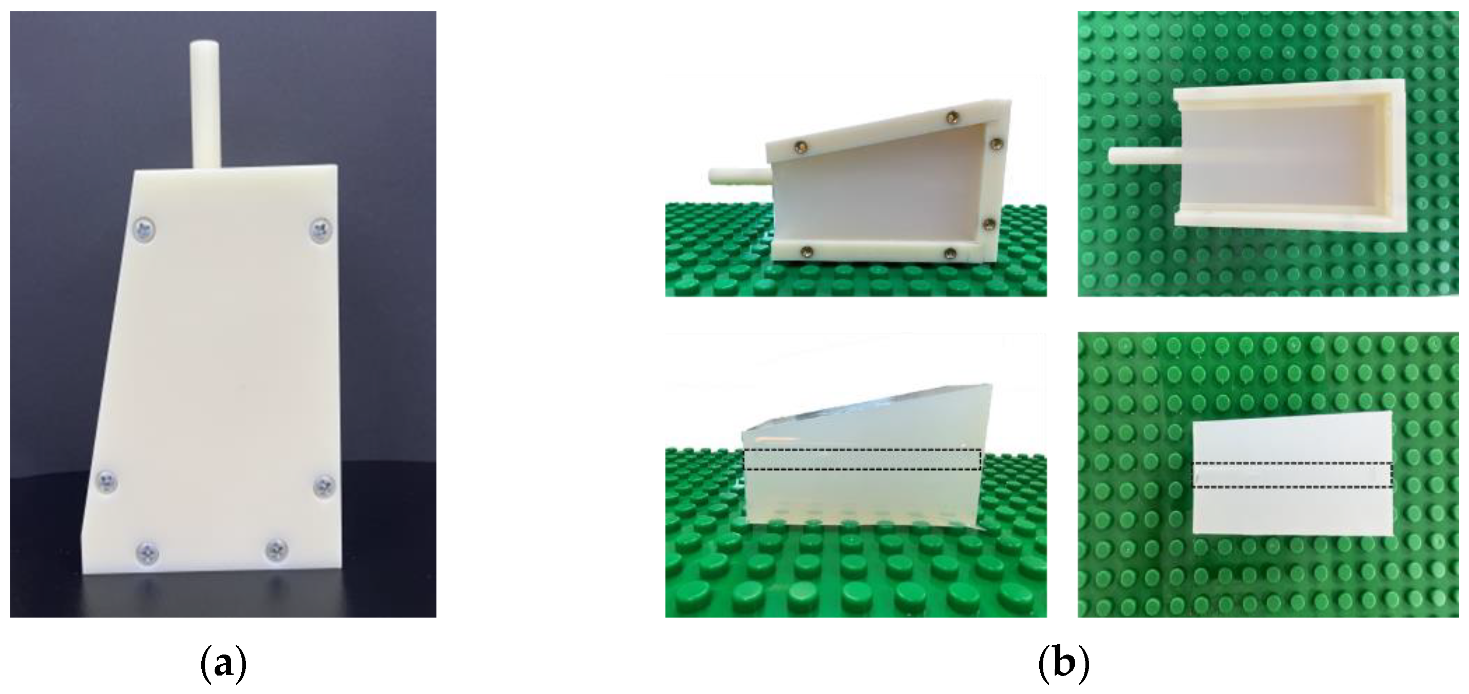
2.1. Vessel-Mimicking Phantom
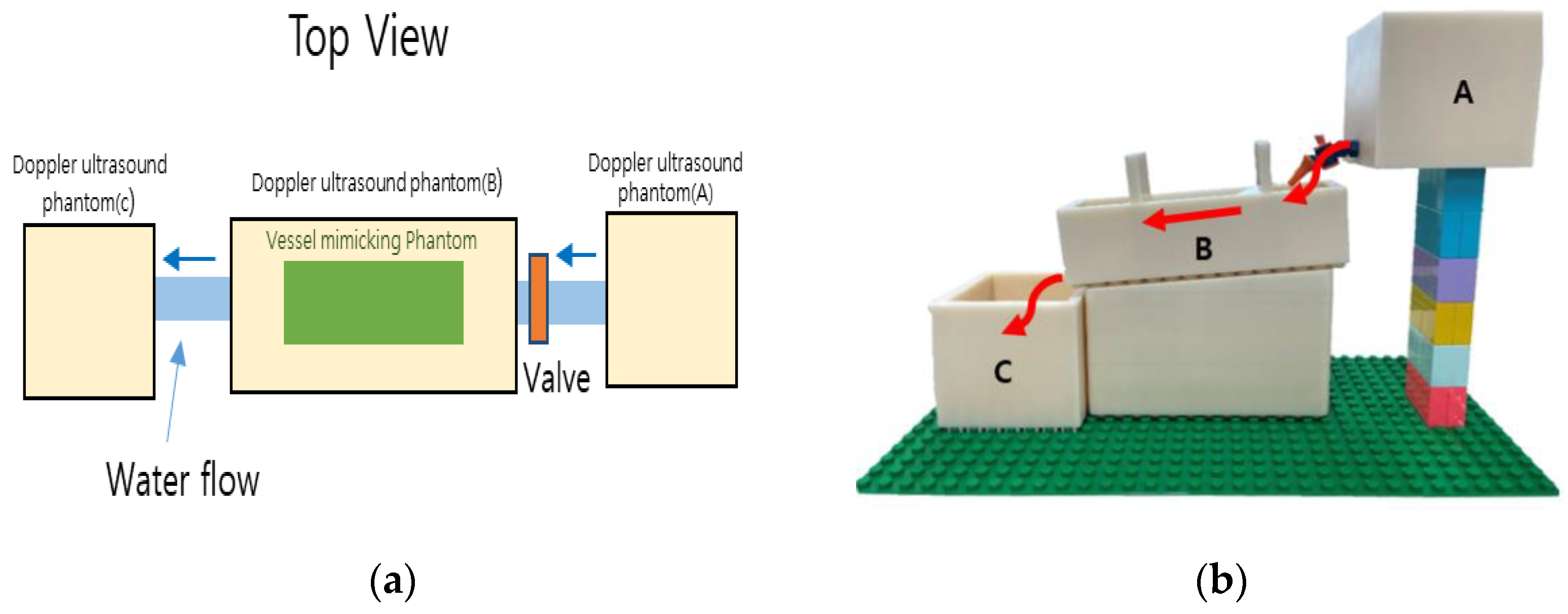
2.2. Dopppler Ultrasound Training Phantom
2.3. Blood-Mimicking Fluid
2.4. Acquisition of Ultrasound Image and Analysis
3. Results
3.1. Vessel-Mimicking Phantom
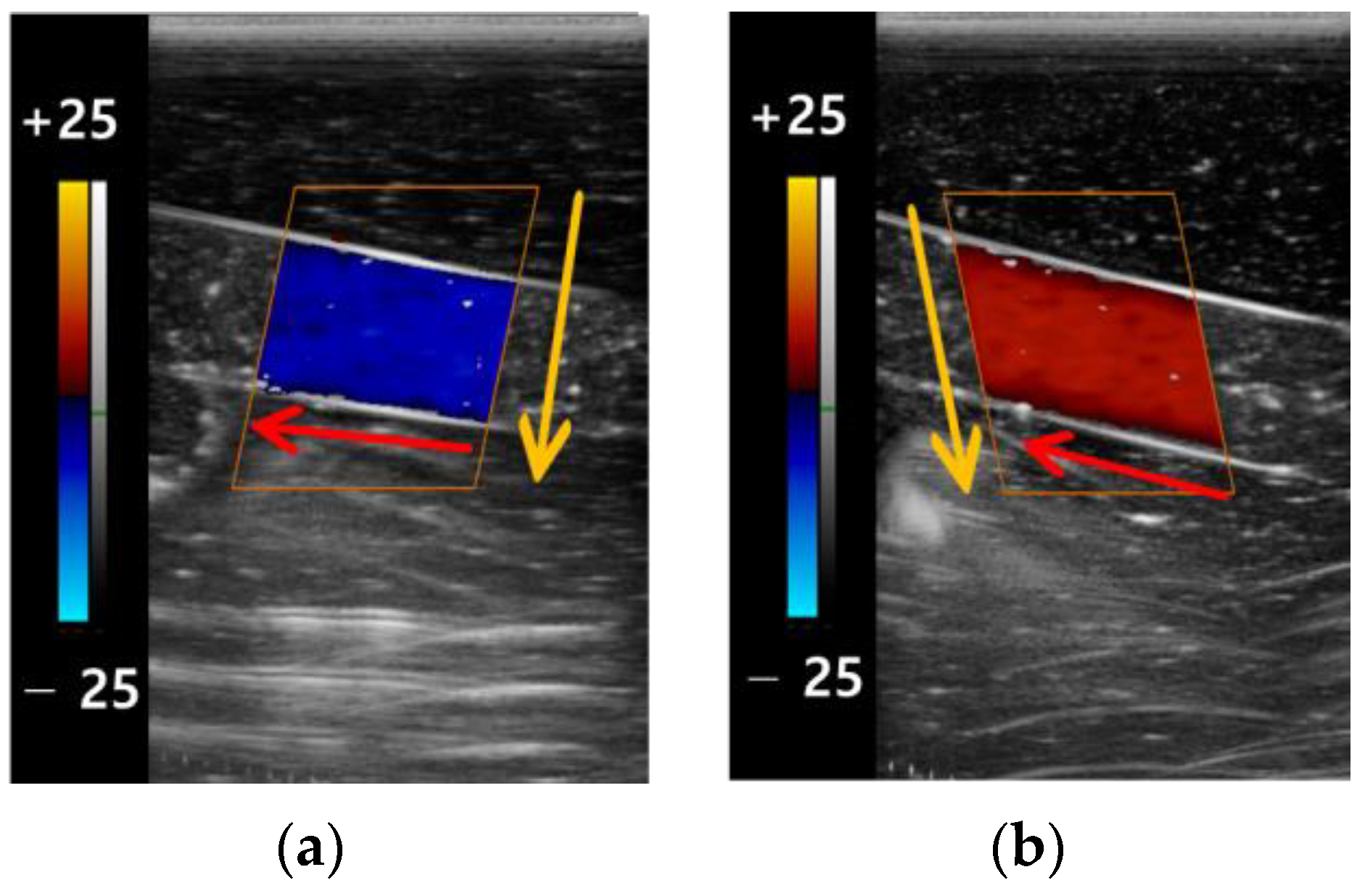
3.2. The Color Doppler Results
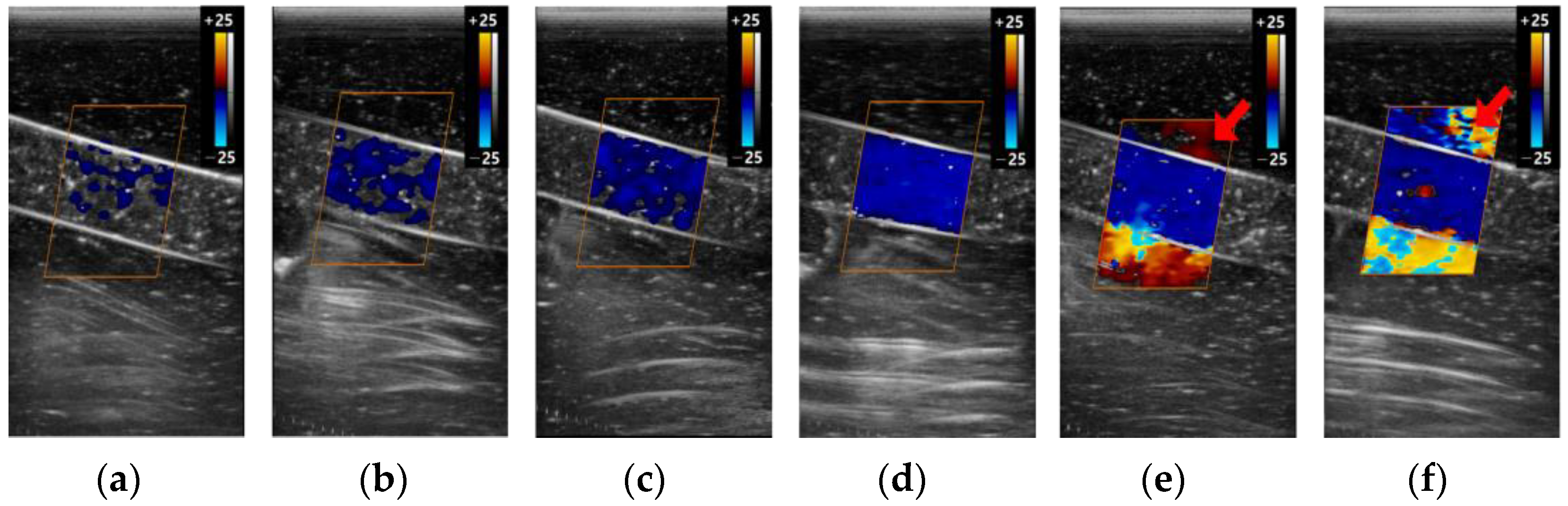
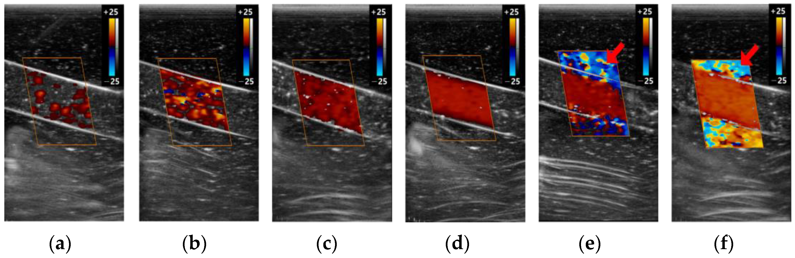
3.2.1. Color Box
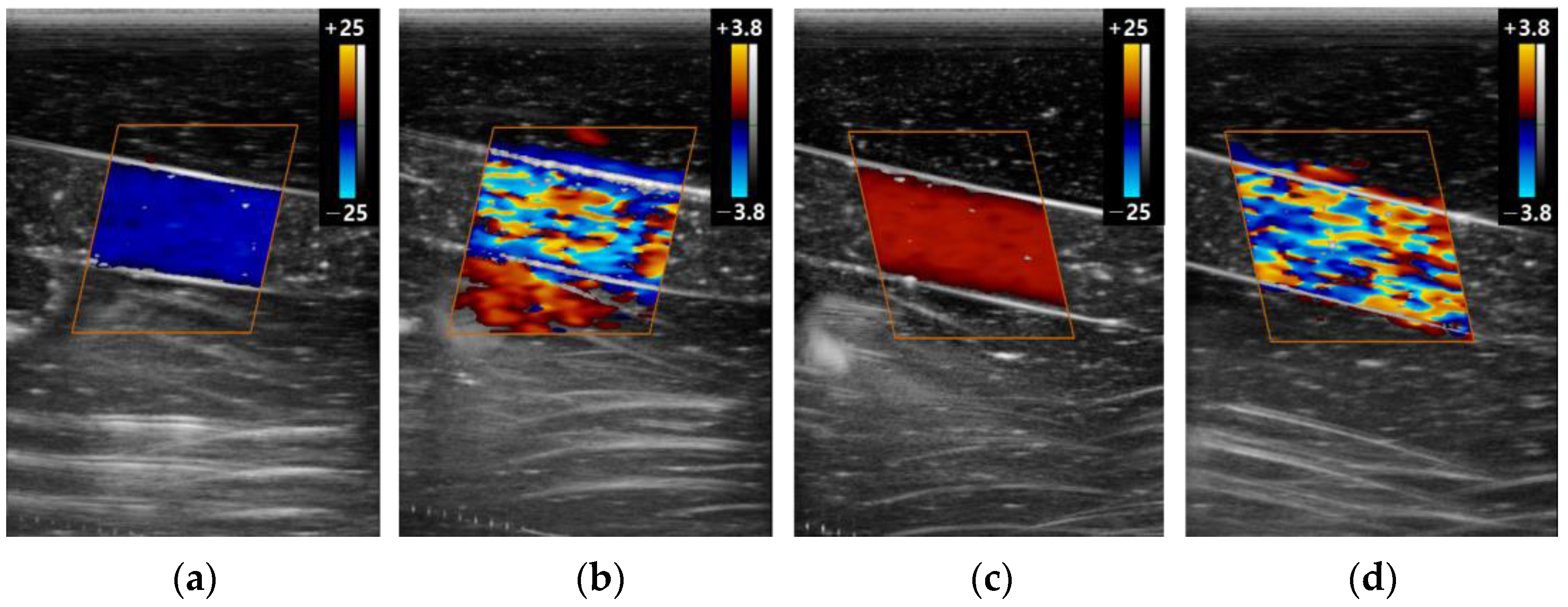
3.2.2. Scale
3.2.3. Gain
4. Discussion
5. Conclusions
Author Contributions
Funding
Institutional Review Board Statement
Informed Consent Statement
Data Availability Statement
Conflicts of Interest
References
- Meyerowitz, C.B.; Fleischer, A.C.; Pickens, D.R.; Thurman, G.B.; Borowsky, A.D.; Thirsk, G.; Hellerqvist, C.G. Quantification of tumor vascularity and flow with amplitude color Doppler sonography in an experimental model: Preliminary results. J. Ultrasound Med. 1996, 15, 827–833. [Google Scholar] [CrossRef]
- Nilsson, A.; Olofsson, P.A.; Lorén, I.; Carlstedt, L.; Nilsson, P. Color Doppler energy: Computer analysis of color to assess angle dependency and detection of volume flow differences. J. Ultrasound Med. 1997, 16, 275–279. [Google Scholar] [CrossRef]
- Karacagil, S.; Löfberg, A.M.; Granbo, A.; Lörelius, L.E.; Bergqvist, D. Value of duplex scanning in evaluation of crural and foot arteries in limbs with severe lower limb ischaemia—A prospective comparison with angiography. Eur. J. Vasc. Endovasc. Surg. 1996, 12, 300–303. [Google Scholar] [CrossRef]
- Kwun, B.-D.; Kwon, Y.; Rhim, S.-C.; Whang, C.-J. Transcranial Doppler ultrasound recording of flow velocity in basal cerebral arteries: Examination technique and normal values in Korean. J. Korean Neurosurg. Soc. 1989, 18, 379–388. [Google Scholar]
- Lee, W. General principles of carotid Doppler ultrasonography. Ultrasonography 2014, 33, 11–17. [Google Scholar] [CrossRef] [PubMed]
- Zagzebski, J.A. Essentials of Ultrasound Physics; Mosby: St. Louis, MO, USA, 1996. [Google Scholar]
- Revzin, M.V.; Imanzadeh, A.; Menias, C.; Pourjabbar, S.; Mustafa, A.; Nezami, N.; Spektor, M.; Pellerito, J.S. Optimizing Image Quality When Evaluating Blood Flow at Doppler US: A Tutorial. Radiographics 2019, 39, 1501–1523. [Google Scholar] [CrossRef]
- Kruskal, J.B.; Newman, P.A.; Sammons, L.G.; Kane, R.A. Optimizing Doppler and color flow US: Application to hepatic sonography. Radiographics 2004, 24, 657–675. [Google Scholar] [CrossRef] [PubMed]
- Ginther, O.; Utt, M.D. Doppler ultrasound in equine reproduction: Principles, techniques, and potential. J. Equine Vet. Sci. 2004, 24, 516–526. [Google Scholar] [CrossRef]
- Kim, Y.H. Ultrasound Phantoms to Protect Patients from Novices. Korean J. Pain. 2016, 29, 73–77. [Google Scholar] [CrossRef] [PubMed]
- Pepley, D.F.; Sonntag, C.C.; Prabhu, R.S.; Yovanoff, M.A.; Han, D.C.; Miller, S.R.; Moore, J.Z. Building ultrasound phantoms with modified polyvinyl chloride: A comparison of needle insertion forces and sonographic appearance with commercial and traditional simulation materials. Simul. Healthc. J. Soc. Simul. Healthc. 2018, 13, 149. [Google Scholar] [CrossRef] [PubMed]
- Jagoda, P.; Stroeder, J.; Buecker, A.; Gawlitza, J.; Frenzel, F.; Raczeck, P. Effectiveness of a brief teaching scenario in a phantom-based learning model for students to achieve ultrasound-guided vascular access—A prospective study. Indian J. Surg. 2020, 85, 234–240. [Google Scholar] [CrossRef]
- Winkler, C.M.; Kuhn, A.I.; Hentschel, G.; Glasmacher, B. A Review on Novel Channel Materials for Particle Image Velocimetry Measurements—Usability of Hydrogels in Cardiovascular Applications. Gels 2022, 8, 502. [Google Scholar] [CrossRef] [PubMed]
- Roghair, I.; Gallucci, F.; van Sint Annaland, M. Novel developments in fluidized bed membrane reactor technology. In Advances in Chemical Engineering; Elsevier: Amsterdam, The Netherlands, 2014; Volume 45, pp. 159–283. [Google Scholar]
- Stoiber, M.; Schlöglhofer, T.; Aigner, P.; Grasl, C.; Schima, H. An alternative method to create highly transparent hollow models for flow visualization. Int. J. Artif. Organs 2013, 36, 131–134. [Google Scholar] [CrossRef] [PubMed]
- Yip, R.; Mongrain, R.; Ranga, A.; Brunette, J.; Cartier, R. Development of anatomically correct mock-ups of the aorta for PIV investigations. In Proceedings of the Canadian Design Engineering Network Conference, Montreal, QC, Canada, 29–30 July 2004. [Google Scholar]
- Yazdi, S.G.; Geoghegan, P.; Docherty, P.; Jermy, M.; Khanafer, A. A review of arterial phantom fabrication methods for flow measurement using PIV techniques. Ann. Biomed. Eng. 2018, 46, 1697–1721. [Google Scholar] [CrossRef] [PubMed]
- Allard, L.; Soulez, G.; Chayer, B.; Treyve, F.; Qin, Z.; Cloutier, G. Multimodality vascular imaging phantoms: A new material for the fabrication of realistic 3D vessel geometries. Med. Phys. 2009, 36, 3758–3763. [Google Scholar] [CrossRef] [PubMed]
- Stanley, N.; Ciero, A.; Timms, W.; Hewlin, R.L., Jr. Development of 3-D Printed Optically Clear Rigid Anatomical Vessels for Particle Image Velocimetry Analysis in Cardiovascular Flow. In Proceedings of the ASME International Mechanical Engineering Congress and Exposition, Salt Lake City, UT, USA, 10–14 November 2019; p. V007T008A004. [Google Scholar]
- Stanley, N.; Ciero, A.; Timms, W.; Hewlin, R.L. A 3-D Printed Optically Clear Rigid Diseased Carotid Bifurcation Arterial Mock Vessel Model for Particle Image Velocimetry Analysis in Pulsatile Flow. ASME Open. J. Eng. 2023, 2, 021010. [Google Scholar] [CrossRef]
- Rickey, D.W.; Picot, P.; Christopher, D.; Fenster, A. A wall-less vessel phantom for Doppler ultrasound studies. Ultrasound Med. Biol. 1995, 21, 1163–1176. [Google Scholar] [CrossRef]
- Hungr, N.; Long, J.A.; Beix, V.; Troccaz, J. A realistic deformable prostate phantom for multimodal imaging and needle-insertion procedures. Med. Phys. 2012, 39, 2031–2041. [Google Scholar] [CrossRef]
- Madsen, E.L.; Hobson, M.A.; Shi, H.; Varghese, T.; Frank, G.R. Tissue-mimicking agar/gelatin materials for use in heterogeneous elastography phantoms. Phys. Med. Biol. 2005, 50, 5597. [Google Scholar] [CrossRef]
- Chao, S.-L.; Chen, K.-C.; Lin, L.-W.; Wang, T.-L.; Chong, C.-F. Ultrasound phantoms made of gelatin covered with hydrocolloid skin dressing. J. Emerg. Med. 2013, 45, 240–243. [Google Scholar] [CrossRef]
- Culjat, M.O.; Goldenberg, D.; Tewari, P.; Singh, R.S. A review of tissue substitutes for ultrasound imaging. Ultrasound Med. Biol. 2010, 36, 861–873. [Google Scholar] [CrossRef]
- Law, Y.F.; Johnston, K.W.; Routh, H.F.; Cobbold, R.S. On the design and evaluation of a steady flow model for Doppler ultrasound studies. Ultrasound Med. Biol. 1989, 15, 505–516. [Google Scholar] [CrossRef]
- Law, Y.F.; Cobbold, R.S.; Johnston, K.W.; Bascom, P.A. Computer-controlled pulsatile pump system for physiological flow simulation. Med. Biol. Eng. Comput. 1987, 25, 590–595. [Google Scholar] [CrossRef] [PubMed]
- Park, H.-Y.; Bae, J.-R.; Kim, J.-K. Manufacture of Flow Phantom with Stenosis and Imaging Evaluation of Power Doppler. J. Acoust. Soc. Korea 2009, 28, 732–739. [Google Scholar]
- Madsen, E.L.; Frank, G.R.; Dong, F. Liquid or solid ultrasonically tissue-mimicking materials with very low scatter. Ultrasound Med. Biol. 1998, 24, 535–542. [Google Scholar] [CrossRef] [PubMed]
- Lee, S.I.; Hong, C.; Lee, C.; Cho, H.-M. Demonstration of Fat Properties in Diagnostic Ultrasound Images through the Development of a Modular Phantom. Appl. Sci. 2022, 13, 432. [Google Scholar] [CrossRef]
- Burlew, M.M.; Madsen, E.L.; Zagzebski, J.A.; Banjavic, R.A.; Sum, S.W. A new ultrasound tissue-equivalent material. Radiology 1980, 134, 517–520. [Google Scholar] [CrossRef]
- Ramnarine, K.V.; Nassiri, D.K.; Hoskins, P.R.; Lubbers, J. Validation of a new blood-mimicking fluid for use in Doppler flow test objects. Ultrasound Med. Biol. 1998, 24, 451–459. [Google Scholar] [CrossRef]
- Eicke, B.; Tegeler, C. Doppler ultrasonography: Physics and principles. In Neurosonology; Mosby-Year Book: St. Louis, MO, USA, 1996; pp. 8–13. [Google Scholar]
- Taylor, K.J.; Holland, S. Doppler US. Part I. Basic principles, instrumentation, and pitfalls. Radiology 1990, 174, 297–307. [Google Scholar] [CrossRef]
- Lee, S.-J.; Yu, S.; Hong, J.M.; Ahn, S.H.; Jeong, S.-K.; Lee, J.Y.; Choi, H.-Y.; Lee, S.I.; Seo, W.-K.; Cho, A.-H. Extracranial Carotid Duplex Ultrasonography. Part I-Basic Principles and Standard Examination for Carotid and Vertebral Arteries, and Jugular Veins. J. Neurosonology Neuroimaging 2018, 10, 47–60. [Google Scholar] [CrossRef]
- Oates, C.P.; Naylor, A.R.; Hartshorne, T.; Charles, S.M.; Fail, T.; Humphries, K.; Aslam, M.; Khodabakhsh, P. Joint recommendations for reporting carotid ultrasound investigations in the United Kingdom. Eur. J. Vasc. Endovasc. Surg. 2009, 37, 251–261. [Google Scholar] [CrossRef] [PubMed]
- Hwang, J.Y. Doppler ultrasonography of the lower extremity arteries: Anatomy and scanning guidelines. Ultrasonography 2017, 36, 111–119. [Google Scholar] [CrossRef] [PubMed]
- Ferreira, J.C.; Ignácio, F.S.; de Meira, C. Doppler ultrasonography principles and methods of evaluation of the reproductive tract in mares. Acta Sci. Vet. 2011, 39, s105–s111. [Google Scholar]
- Zagzebski, J. Physics and instrumentation in Doppler and B-mode ultrasonography. In Introduction to Vascular Ultrasonography; WB Saunders Co.: Philadelphia, PA, USA, 1992; pp. 19–43. [Google Scholar]
- Mitchell, C.; Rahko, P.S.; Blauwet, L.A.; Canaday, B.; Finstuen, J.A.; Foster, M.C.; Horton, K.; Ogunyankin, K.O.; Palma, R.A.; Velazquez, E.J. Guidelines for Performing a Comprehensive Transthoracic Echocardiographic Examination in Adults: Recommendations from the American Society of Echocardiography. J. Am. Soc. Echocardiogr. 2019, 32, 1–64. [Google Scholar] [CrossRef] [PubMed]
- Uppal, T.; Mogra, R. RBC motion and the basis of ultrasound Doppler instrumentation. Australas. J. Ultrasound Med. 2010, 13, 32–34. [Google Scholar] [CrossRef]
- Hines, C.D.; Yu, H.; Shimakawa, A.; McKenzie, C.A.; Brittain, J.H.; Reeder, S.B. T1 independent, T2* corrected MRI with accurate spectral modeling for quantification of fat: Validation in a fat-water-SPIO phantom. J. Magn. Reson. Imaging 2009, 30, 1215–1222. [Google Scholar] [CrossRef] [PubMed]
- Hernando, D.; Sharma, S.D.; Aliyari Ghasabeh, M.; Alvis, B.D.; Arora, S.S.; Hamilton, G.; Pan, L.; Shaffer, J.M.; Sofue, K.; Szeverenyi, N.M.; et al. Multisite, multivendor validation of the accuracy and reproducibility of proton-density fat-fraction quantification at 1.5T and 3T using a fat-water phantom. Magn. Reson. Med. 2017, 77, 1516–1524. [Google Scholar] [CrossRef]
- Jang, J.K.; Lee, S.S.; Kim, B.; Cho, E.S.; Kim, Y.J.; Byun, J.H.; Park, B.J.; Kim, S.Y.; Kim, J.H. Agreement and Reproducibility of Proton Density Fat Fraction Measurements Using Commercial MR Sequences Across Different Platforms: A Multivendor, Multi-Institutional Phantom Experiment. Investig. Radiol. 2019, 54, 517–523. [Google Scholar] [CrossRef]
- McGarry, C.K.; Grattan, L.J.; Ivory, A.M.; Leek, F.; Liney, G.P.; Liu, Y.; Miloro, P.; Rai, R.; Robinson, A.P.; Shih, A.J.; et al. Tissue mimicking materials for imaging and therapy phantoms: A review. Phys. Med. Biol. 2020, 65, 23TR01. [Google Scholar] [CrossRef]
- Cho, H.-M.; Hong, C.; Lee, C.; Ding, H.; Kim, T.; Ahn, B. LEGO-compatible modular mapping phantom for magnetic resonance imaging. Sci. Rep. 2020, 10, 14755. [Google Scholar] [CrossRef]
- Xiao, Y.; Yan, C.X.; Drouin, S.; De Nigris, D.; Kochanowska, A.; Collins, D.L. User-friendly freehand ultrasound calibration using LEGO bricks and automatic registration. Int. J. Comput. Assist. Radiol. Surg. 2016, 11, 1703–1711. [Google Scholar] [CrossRef] [PubMed]
- Walsh, R.; Soehl, M.; Rankin, A.; Lasso, A.; Fichtinger, G. Design of a tracked ultrasound calibration phantom made of LEGO bricks. In Proceedings of the Medical Imaging 2014: Image-Guided Procedures, Robotic Interventions, and Modeling, San Diego, CA, USA, 15–20 February 2014; pp. 606–612. [Google Scholar]


| Color Box | Scale | Gain | ||||
|---|---|---|---|---|---|---|
| 2D | Color | 2D | Color | 2D | Color | |
| Depth (mm) | 45 | - | 45 | - | 45 | - |
| Gain (dB) | 73 | 35 | 73 | 35 | 73 | 2, 5, 10, 35, 60, 100 |
| Dynamic range (dB) | 105 | - | 105 | - | 105 | - |
| Frame average | 10 | 4 | 10 | 4 | 10 | 4 |
| Power (W) | 90 | - | 90 | - | 90 | - |
| Scale (kHz) | - | 4 | - | 0.6, 4 | - | 4 |
| Wall filter | - | 0 | - | 0 | - | 0 |
Disclaimer/Publisher’s Note: The statements, opinions and data contained in all publications are solely those of the individual author(s) and contributor(s) and not of MDPI and/or the editor(s). MDPI and/or the editor(s) disclaim responsibility for any injury to people or property resulting from any ideas, methods, instructions or products referred to in the content. |
© 2023 by the authors. Licensee MDPI, Basel, Switzerland. This article is an open access article distributed under the terms and conditions of the Creative Commons Attribution (CC BY) license (https://creativecommons.org/licenses/by/4.0/).
Share and Cite
Kim, N.; Hong, C.; Lee, C.; Cho, H.-M. Development and Evaluation of Doppler Ultrasound Training Phantom for Human Vessel Simulation. Appl. Sci. 2023, 13, 9932. https://doi.org/10.3390/app13179932
Kim N, Hong C, Lee C, Cho H-M. Development and Evaluation of Doppler Ultrasound Training Phantom for Human Vessel Simulation. Applied Sciences. 2023; 13(17):9932. https://doi.org/10.3390/app13179932
Chicago/Turabian StyleKim, Nagyum, Cheolpyo Hong, Changwoo Lee, and Hyo-Min Cho. 2023. "Development and Evaluation of Doppler Ultrasound Training Phantom for Human Vessel Simulation" Applied Sciences 13, no. 17: 9932. https://doi.org/10.3390/app13179932