Article

Dynamic Modeling of Motorized Spindle System with Unbalanced Mass and Spindle Inclination

School of Mechatronic Engineering and Automation, Shanghai University, Shanghai 200444, China
*
Authors to whom correspondence should be addressed.
Appl. Sci. 2023, 13(18), 10053; https://doi.org/10.3390/app131810053
Submission received: 15 June 2023 / Revised: 1 September 2023 / Accepted: 3 September 2023 / Published: 6 September 2023

Abstract

:
The high-speed motorized spindle has been wildly used in the field of aerospace processing, due to its advantages such as high speed, high precision, and high efficiency. CNC machine tools used for processing aerospace products require high machining accuracy, and once the spindle fails, it will seriously affect the quality of product processing. Thus, it is important to study the faults of the spindle, especially the faults caused by subtle errors. In this work, a dynamic model of a spindle with unbalanced mass fault and spindle inclination fault is established, and the natural frequencies and mode shapes of the motorized spindle are calculated by using the whole transfer matrix method (WTMM). The deflections of the spindle initial end in the different situations are discussed when the two faults happen independently. The results show that the spindle end deflection of the same fault has different sensitivity at different speeds. At the third order of natural frequencies, the deflection of a motorized spindle is greatest regardless of the fault that occurs. Although the motorized spindle rotates at the same speed, different faults could cause different mode shapes. At the lower speed, when the unbalanced mass fault happens, the mode shape is in an arched shape, and while the spindle inclination fault happens, the mode shape is in a concave shape.

1. Introduction

Aerospace products are mostly thin-walled parts with complex shapes, needed to suit the specific working environment and performance demands, and are typically processed using high-speed milling. In the field of aerospace processing, there are strict requirements for the precision of machine tool processing, in which the precision of the motorized spindle plays a vital role in the whole processing. The common faults of motorized spindles include spindle fault [1,2,3], bearing fault [4,5], lubrication system fault [6], stator and rotor fault [7,8], spindle housing fault [9], and cooling system fault [10]; the bearing fault is the most common and analyzed fault. However, compared with other faults, the spindle fault is more difficult to find and more likely to affect the progress of this machining. For aerospace equipment, a small error may lead to the failure of the whole mechanism, so the faults of motorized spindles cannot be ignored in the processing of aerospace equipment.
In recent years, the fault dynamics of motorized spindles have become an important issue. Wang et al. (2018) [11] established a dynamic model of a dual-rotor system to solve its unbalanced misalignment coupling faults. Xu et al. (2016) [12] obtained the unbalanced magnetic pull by numerical method and discussed the effects of initial static eccentricity on displacement spectra. Liu et al. (2019) [13] established a dynamic model of the permanent magnet synchronous motors’ rotor-bearing system which considers unbalanced magnetic pull and the nonlinear restoring force. They concluded that unbalanced magnetic pull causes a negative stiffness effect on the natural frequencies. Werner (2017) [14] established an analytical rotor dynamic model which considers mass eccentricity, bent rotor deflection, and magnetic eccentricity. Zuo et al. (2018) [15] analyzed and modeled the longitudinal dynamics of the motorized spindle under the excitation of torque ripple. Based on the Jeffcott rotor model, Xiang et al. (2016) [16] analyzed the stiffness characteristics of the rotor system of the permanent magnet synchronous motors. Kumar (2017) [17] gave the reason of unbalanced magnetic pull. Based on the law of energy conservation, Bossmanns and Tu (2001) [18] presented a power flow model of high-speed motorized spindles. Li et al. (2004) [19,20] established a comprehensive integrated thermo-dynamic model for high-speed spindles. Xu et al. (2017) [21] built the dynamic model of the motorized spindle system. They used this dynamic model to show that the vibrations are proportional to the mass of the unbalance. Liu et al. (2016) [22] presented an improved dynamic model for unbalanced high-speed motorized spindles, and obtained the sensitivities of the motorized spindles.
Although a huge number of scholars have contributed to this research, the fault dynamics of motorized spindles still have some unsolved problems, such as the vibration of motorized spindles caused by the unbalanced mass and inclined axis. In practical engineering, the two kinds of faults will occur due to the uneven distribution of rotor material density during the manufacturing process or errors caused by the installation of a motorized spindle. Although the faults in these two cases can be quickly solved after discovery, they will still affect the normal operation of the motorized spindle before discovery. Moreover, it is also very important to judge whether these two faults occur. If they are found as early as possible, their influence on the normal operation of the whole machinery can be avoided. Therefore, it is necessary to analyze the influence of these two kinds of faults on the vibration of the spindle, so as to help the operator find out whether the faults happen as soon as possible.
In this work, a model of motorized spindles based on the whole transfer matrix method (WTMM) is established and a model of a spindle with fault caused by unbalanced mass or spindle inclination is given in Section 2. Then, a case study we conducted on a certain type of high-speed motorized spindle is described by using these models in Section 3. The deflection of the spindle end in different conditions is discussed and the mode shapes of the motorized spindle are presented considering the unbalanced mass fault and the spindle inclination fault, respectively. The research in this paper provides theoretical guidance for the design, operation, and maintenance of motorized spindles, which can effectively improve the accuracy and production efficiency of high-speed machining, and promote the development of a series of related technologies such as high-speed feed, high-performance tools, detection, and control.

2. Dynamic Modeling

The structure diagram of a high-speed motorized spindle is shown in Figure 1. Its main parts include a rotor spindle, shell, stator, and bearings. Figure 1b shows the structure diagram of a motorized spindle-bearing system.
Compared with other methods, the whole transfer matrix method (WTMM) has more efficient computing power and more extensive application capabilities [23,24]. So, in this paper, it is used to analyze the unbalanced mass fault and spindle inclination fault of a motorized spindle.
According to the WTMM, a motorized spindle is divided into subsegments. By lumped mass and lumped moment of inertia method, as shown in Figure 1c, every subsegment is simplified into two rigid discs which are connected by massless elastic shaft. The unit is formed by a disc and a shaft, and two units are connected by the node. Each node has four effective parameters: section deflection (radial displacement) y, section rotation angle θ, section bending moment M, and section shear force Q. The vector composed of these four effective parameters is the cross-sectional state vector, which is recorded as
Z = y θ M Q T

2.1. Dynamic Modeling of Motorized Spindle without Fault

As shown in Figure 2a, the forces of the left and right sections of the rigid thin disc have a bending moment of M L and M R and a shear force of Q R and Q L .
The equations of inertia force and moment of inertia are as follows [25]:
F = m ω 2 y
M = J d J p Ω ω ω 2 θ
where y is the deflection of the disc, θ is the rotation angle of the disc, Ω is the rotation angular velocity of the rotor, and ω is the whirling angular velocity, Jd and Jp are the polar and equatorial moment of inertia, respectively. When the node is unsupported, the inertia force is zero. The D’Alembert equation can be established as follows:
y R = y L θ R = θ L M R = M L J d J p Ω ω ω 2 θ + k θ θ Q R = m ω 2 y + Q L k r y
where k r is the radial stiffness of the bearing and k θ is the angular stiffness of the bearing.
Equation (4) is expressed in the form of a matrix to obtain
y θ M Q i R = 1 0 0 0 0 1 0 0 0 k θ J d J p Ω ω ω 2 1 0 m ω 2 k r 0 0 1 i y θ M Q i L
where y , θ , M , and Q are the deflection, rotation angle, bending moment, and shear force of the disc, respectively. The superscript R or L indicates the right side or left side of the disc. The subscript i indicates the disc of the ith unit. Therefore, when the disc left side cross-sectional state of the ith unit is known, Equation (5) can be used to solve its right side cross-sectional state.
Similarly, as shown in Figure 2b, the left end of the elastic shaft connects the disc’s right side of the same unit, and the right end of the shaft connects the left side of the disc which belongs to the next disc –shaft unit. Therefore, the shear force and bending moment at the left end of the shaft are superscripted as R and subscripted as i . The shear force and bending moment at the right end are superscripted as L and subscripted as i + 1 .
It is also known from the bending deformation conditions of shafts in the mechanics of materials that
y i + 1 = y i + θ i l i + M i + 1 L l i 2 2 E i I i Q i + 1 L l i 3 3 E i I i + k s l i G i A i θ i + 1 = θ i + M i + 1 L l i E i I i Q i + 1 L l i 2 2 E i I i M i + 1 L = M i R + Q i R l i Q i + 1 L = Q i R
where k s is the shape factor of the section, for the round solid shaft k s = 10/9. G i is the shear modulus of the ith subsegment unit, A i is the sectional area of the ith subsegment unit, E i is the modulus of elongation of the subsegment, and I i is the inertia moment of the ith subsegment.
Similarly, by changing the above equation into matrix form, the following formula can be obtained:
y θ M Q i + 1 L = 1 l l 2 2 E I l 3 6 E I 1 v   0 1 l E I l 2 2 E I 0 0 1 l 0 0 0 1 i y θ M Q i R
where v = k s 6 E i I i / G i A i l i 2 is called the shear effect coefficient. The vector on the left side of the equation is the cross-sectional state vector at the right end of the massless elastic shaft in the ith unit, that is, the cross-sectional state vector at the left side of the disc in the (i + 1)th unit.
The transfer matrix of the whole unit can be obtained by combining the two equations of the same unit.
y θ M Q i + 1 L = 1 l l 2 2 E I l 3 6 E I 1 v 0 1 l E I l 2 2 E I 0 0 1 l 0 0 0 1 i × 1 0 0 0 0 1 0 0 0 k θ J d J p Ω ω ω 2 1 0 m ω 2 k r 0 0 1 i y θ M Q i L
y θ M Q i + 1 L = 1 1 + l 3 6 E I 1 v m ω 2 k r l + l 2 2 E I k θ ( J d J p Ω ω ) ω 2 l 2 2 E I l 3 6 E I 1 v l 2 2 E I m ω 2 k r 1 + l E I k θ ( J d J p Ω ω ) ω 2 l E I l 2 2 E I l m ω 2 k r k θ ( J d J p Ω ω ) ω 2 1 l m ω 2 k r 0 0 1 i y θ M Q i L
Equation (9) indicates that the cross-sectional state vector at the left end of the ith unit is transferred to the right end of the unit, that is, the left end of the next unit. For convenience of description, Equation (9), can be written as Z i + 1 L = T i Z i L , where T i is the transfer matrix between units.

2.2. Dynamic Modeling of Motorized Spindle with Unbalanced Mass Fault

Unbalanced mass fault is the simplest and most common fault form of the motorized spindle. When an unbalanced mass fault occurs, the center line of the mass and the center line of the rotation are in the same plane, and the distance between them is r , which is called eccentricity. Therefore, the unbalanced force will be generated at this time:
F = U ω 2
where U = m r , m is the unbalanced mass.
Under the influence of the unbalanced force, the force state of the disc will change as shown in Figure 3. The D’Alembert equation is then re-established:
M R = M L J d J p Ω ω ω 2 θ + k θ θ + U ω 2 Q R = m ω 2 y + Q L k r y
It is expressed in the form of a matrix to obtain
y θ M Q i + 1 L = 1 l l 2 2 E I l 3 6 E I ( 1 v ) 0 1 l E I l 2 2 E I 0 0 1 l 0 0 0 1 i × 1 0 0 0 0 1 0 0 0 k θ ( J d J p Ω ω ) ω 2 1 0 m ω 2 k r 0 0 1 i y θ M Q i L + 0 0 0 U i i ω 2
y θ M Q i + 1 L = 1 1 + l 3 6 E I 1 v m ω 2 k r l + l 2 2 E I k θ ( J d J p Ω ω ) ω 2 l 2 2 E I l 3 6 E I 1 v l 2 2 E I m ω 2 k r 1 + l E I k θ ( J d J p Ω ω ) ω 2 l E I l 2 2 E I l m ω 2 k r k θ ( J d J p Ω ω ) ω 2 1 l m ω 2 k r 0 0 1 i y θ M Q i L + α l α 0 0 i
As the motorized spindle without fault, for convenience of description, Equation (13) can be written as Z i + 1 L = T i Z i L + H i , where T i is the transfer matrix between units and the H i is unbalance vector.

2.3. Dynamic Modeling of Motorized Spindle with Spindle Inclination Fault

As the inclination angle is relatively small in practical work, once it is ignored, it may lead to further serious failure problems such as the spindle hitting the film or misalignment. Therefore, it is necessary to study the influence of the inclination angle on the dynamic characteristics of a motorized spindle.
As shown in Figure 4, when the motorized spindle inclines, an inclination angle of magnitude is generated between the axis and the horizontal line. Because it is small,
sin α = α cos α = 1
Due to the existence of the inclination angle, the actual value of the rotation angle at the right end of the spindle is the calculated rotation angle plus the inclination angle caused by the inclination, and the deflection will also be increased in the same way. The bending deformation analysis of the elastic shaft shows that
y i + 1 = y i + θ i l i + M i + 1 L l i 2 2 E i I i Q i + 1 L l i 3 3 E i I i + k s l i G i A i + α l i θ i + 1 = θ i + M i + 1 L l i E i I i Q i + 1 L l i 2 2 E i I i + α M i + 1 L = M i R + Q i R l i Q i + 1 L = Q i R
where α is the small angle at which the axis of the motorized spindle is inclined. The equation can be obtained by changing the above formula into matrix form:
y θ M Q i + 1 L = 1 l l 2 2 E I l 3 6 E I 1 v   0 1 l E I l 2 2 E I 0 0 1 l 0 0 0 1 i y θ M Q i R + α l α 0 0 i
Therefore, the transfer matrix of the whole unit is
y θ M Q i + 1 L = 1 + l 3 6 E I 1 v m ω 2 k r l + l 2 2 E I k θ ( J d J p Ω ω ) ω 2 l 2 2 E I l 3 6 E I 1 v l 2 2 E I m ω 2 k r 1 + l E I k θ ( J d J p Ω ω ) ω 2 l E I l 2 2 E I l m ω 2 k r k θ ( J d J p Ω ω ) ω 2 1 l m ω 2 k r 0 0 1 i y θ M Q i L + l 3 6 E I 1 v l 2 2 E I l 1 i U i ω 2
As with other conditions, Equation (17) is written as Z i + 1 L = T i Z i L + B i , where T i is the transfer matrix between units and B i is the unbalance vector.

3. Results and Discussion

The parameters of a certain high-speed motorized spindle used in a practical machining machine tool for aviation components are shown in Table 1.

3.1. Dynamic Characteristics of Motorized Spindle without Fault

From Section 2.1, the general equation from the first node to the last node can be written as
Z n + 1 = T n Z n = T n T n 1 Z n 1 = = T n T n 1 T 1 Z 1 = T a l l Z 1
where Z n + 1 is the last subsegment state vector of the motorized spindle, Z 1 is the initial subsegment state vector of the motorized spindle, and T a l l is the total transfer matrix obtained by sequentially multiplying the transfer matrices of all units from the first to the last. Because both ends of the motorized spindle are free ends, we know that some parameters of the end, that is, the bending moment and shear force of these two sections, are zero. Therefore,
Δ ω = a 31 a 32 a 41 a 42 = m ω 2 k r k θ J d J p Ω ω ω 2 = 0
where the critical angular velocity can be obtained by Ref. [26], a 31 , a 32 , a 41 , and a 42 are the elements in the first or second columns of the third row and the first or second columns of the fourth row of the total transfer matrix, respectively, which contain the parameter angular velocity of ω .
Figure 5 shows the curve of angular velocity with change and the iterative method is used to solve the problem in a small range of approximately 0. When Δω = 0, the value corresponding to the horizontal coordinate is the critical rotational speed. Within the specified operating speed range of the motorized spindle, there are four points satisfied as Δ ω 0 . This means that the system has four critical speeds, which are 16,255.16, 24,526.62, 36,430.34, and 53,907.12 rpm.
After the critical rotational speed is obtained, the relationship between the deflection of the initial end y 1 and the rotation angle of the initial end θ 1 can be obtained by bringing the corresponding value of ω into Equation (18). For convenience of calculation, a dimensionless calculation is usually carried out, and the deflection of the initial end y 1 is set to 1. The angle θ 1 can be obtained as follows:
y θ L = a 31 a 32 a 41 a 42 y θ R θ L = a 41 y R + a 42 θ R = 0 θ R = a 41 a 42 y R = α y R θ 1 = a 41 a 42 y 1 = α y 1
From this, the normalized state vector of the initial end at a certain critical speed can be obtained as follows:
Z 1 = 1 α 0 0 T
Equation (21) is multiplied by the element transfer matrix of each element in turn to obtain the cross-sectional section state vector of the corresponding node. At the different critical speeds, the deflection of each node can be calculated, and the mode shapes are shown in Figure 6.
From (a–d) in Figure 6, it can be seen that under different critical speeds, the radial displacement of the spindle changes with the axial direction of the motorized spindle, and the vibration of the motorized spindle is different at different critical speeds.

3.2. Dynamic Characteristics of Motorized Spindle with Unbalanced Mass Fault

From Section 2.2, when the unbalanced mass fault happens, the general equation from the first node to the last node can be written as
Z n + 1 = T n Z n + H n = T n ( T n 1 Z n 1 + H n 1 ) + H n = = T a l l Z 1 + k = 1 n ( j = k + 1 n T j H k ) = T a l l Z 1 + H a l l
where H a l l is the sum of the unbalanced vector of all units from left to right. It is the same as the condition of the motorized spindle without fault; both ends of the spindle are free ends. The equation of angular velocity can be obtained:
y θ 1 = a 31 a 32 a 41 a 42 1 h 3 h 4
where a 31 , a 32 , a 41 and a 42 are the elements in the first or second columns of the third row and the first or second columns of the fourth row of the total transfer matrix, respectively. h 3 and h 4 are the third and fourth elements of h a l l . All of them contain the parameter angular velocity of ω . y and θ indicate the section deflection and rotation angle of the initial end of the spindle, respectively.
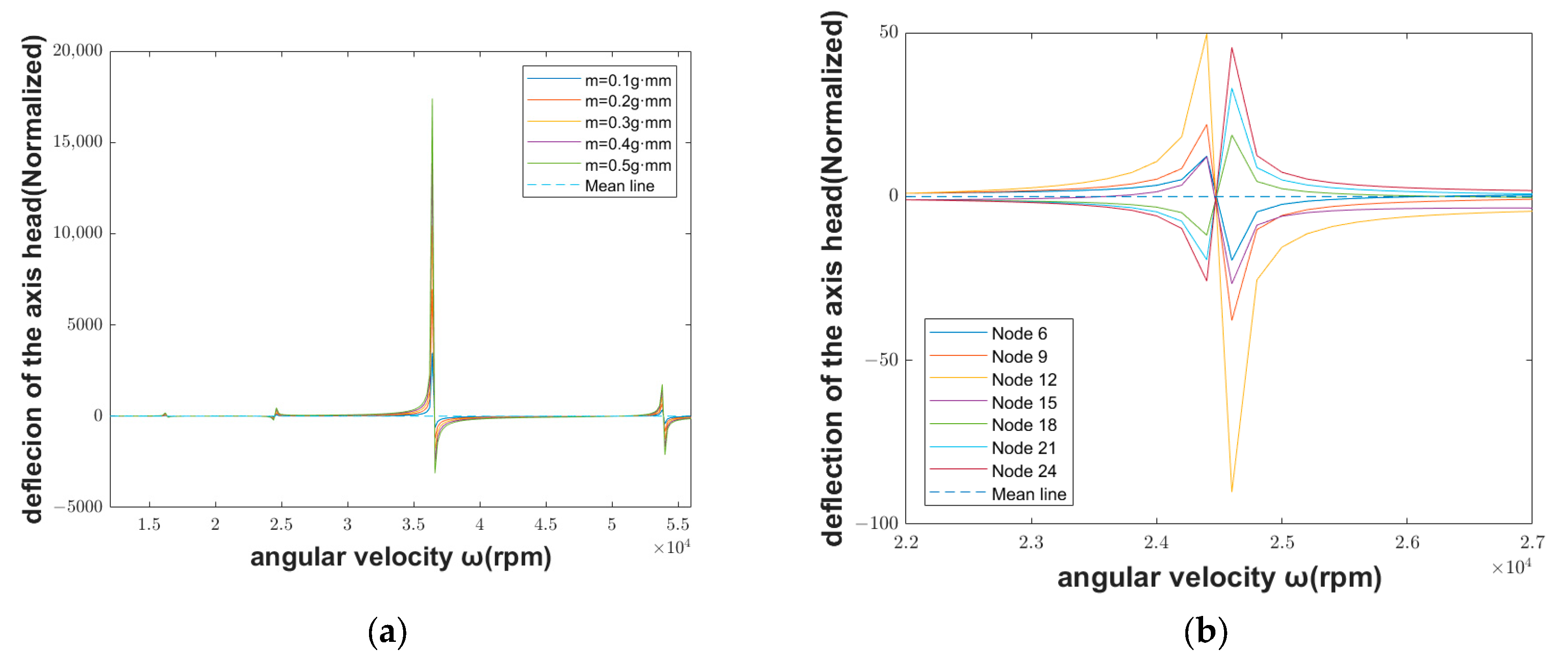
Assuming that the amount of unbalance is 1–5 g·mm, the section deflection and rotation angle of different initial ends can be obtained under different angular velocities. Within the whole specified rotating speed, when the whole spindle is unbalanced, the deflection of the spindle initial end is shown in Figure 7a. Around the second-order critical rotating speed, the schematic diagram of the unbalanced mass fault influence on the deflection of the spindle intimal end when the amount of unbalance exists in different units is shown in Figure 7b.
As can be seen from Figure 7a, the deflection of the spindle initial end increases gradually at first when the unbalanced mass fault occurs, and reaches a local maximum when it reaches the first-order critical speed. At this time, the deflection direction of the shaft end suddenly changes. With the further increase in rotational speed, the deflection of the spindle initial end continues to increase along this direction and the direction suddenly changes again when the second-order critical rotational speed is reached. The same characteristics are shown at the third-order and fourth-order critical speeds. Moreover, the maximum value is reached at the third-order critical speed.
It can be seen from Figure 7b that the direction and magnitude of the spindle initial end deflection are different in different units when the unbalanced mass faults occur. The spindle initial end deflection is upward when a fault occurs in the 6th, 9th, 12th, or 15th unit. When the speed reaches the second-order critical speed, the direction suddenly changes, and the deflection value of the 12th unit is the largest, which may be more sensitive to the unbalanced fault. On the other hand, the spindle initial end deflection of the 18th, 21st, and 24th units are downward, and the direction suddenly changes when it reaches the second-order critical speed too.
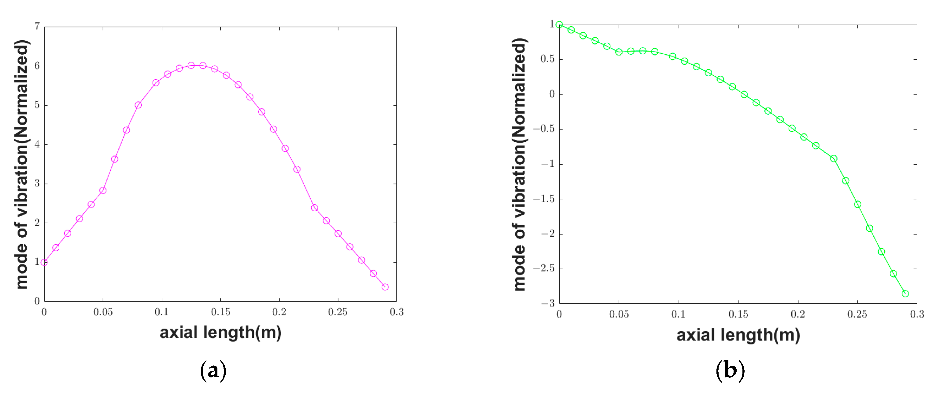
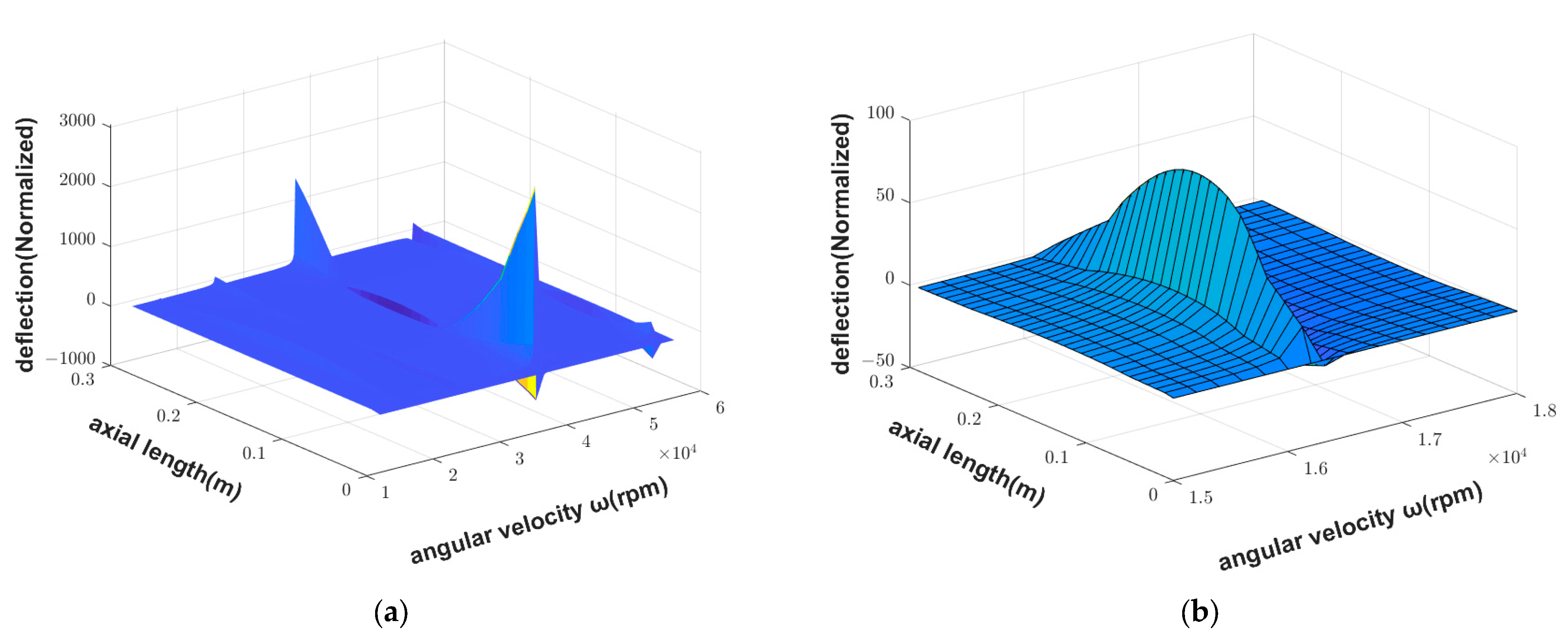
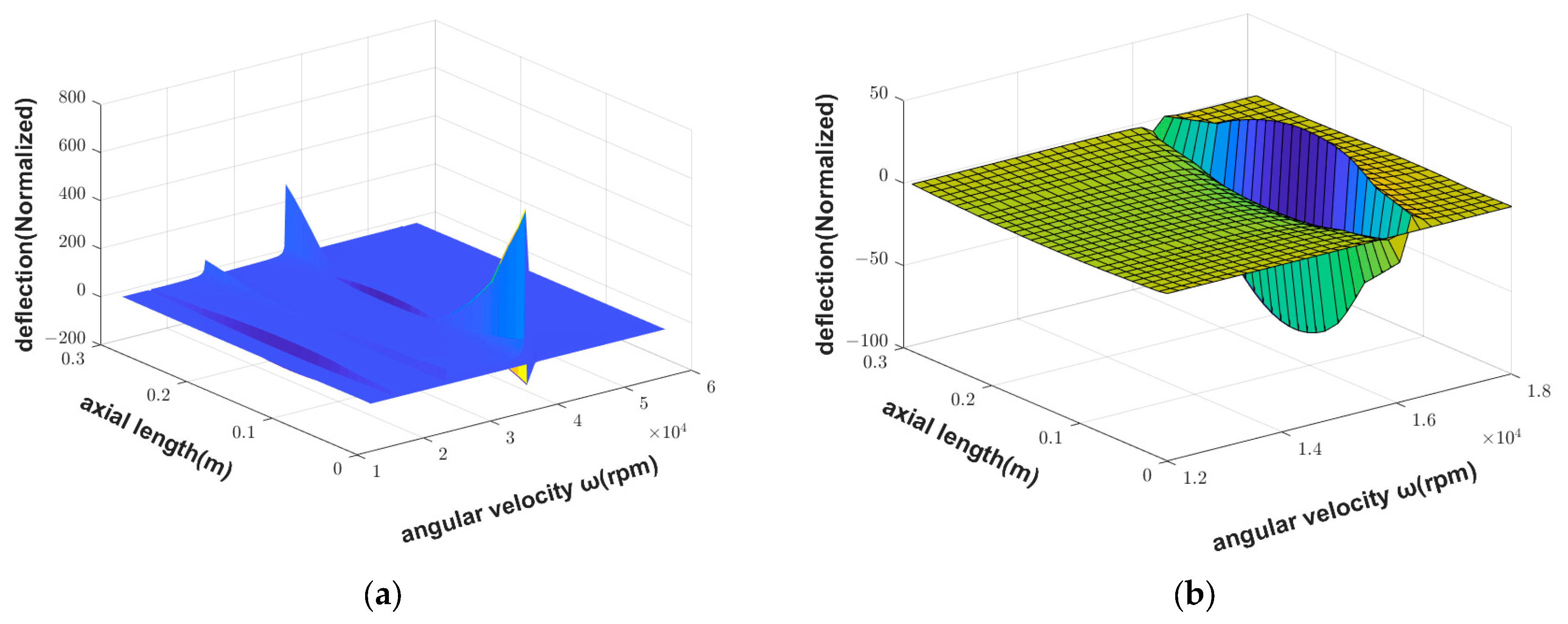
The vibration mode of the whole motorized spindle can be further solved when the unbalanced mass fault occurs, as shown in Figure 8a. Around the first-order critical speed, the influence of the unbalanced mass fault on the middle part of the spindle is slightly greater than that on the spindle ends. While with the increase in speed, the influence of the unbalanced mass fault on the spindle ends begins to be greater than that on the middle part of the spindle around the second-order and third-order critical speeds. Around the third-order critical speed, the influence on the spindle end reaches the maximum value. After the rotating speed continues to increase, the degree of influence between the spindle end and the middle part of the spindle caused by the unbalanced mass fault gradually decreases.
The vibration mode of the whole motorized spindle under the unbalanced mass fault is further analyzed around the first-order critical speed, as shown in Figure 8b. Before reaching the first-order critical speed, the middle part of the spindle deflection is upward and greater than the spindle end deflection. Therefore, at this time, the motorized spindle is arched upward. However, when the first-order critical speed is reached, the middle part of the spindle deflection begins to change to the opposite direction, so the whole spindle is in a concave shape.
It can be seen that the dynamic characteristics of the whole spindle cannot be ignored when the unbalanced mass fault occurs, especially when the speed is close to the critical speed, and different parts of the spindle have a different sensitivity to unbalanced mass faults.

3.3. Dynamic Characteristics of Motorized Spindle with Spindle Inclination Fault

From Section 2.3, when the spindle inclination fault occurs, the general equation from the first node to the last node can be written as
Z n + 1 = T n Z n + B n = T n ( T n 1 Z n 1 + B n 1 ) + B n = = T a l l Z 1 + k = 1 n ( j = k + 1 n T j B k ) = T a l l Z 1 + B a l l
where B a l l is the sum of the unbalance vector of all units from left to right. Both ends of the spindle are free ends. The equation of angular velocity is
y θ 1 = a 31 a 32 a 41 a 42 1 b 3 b 4
where b 3 and b 4 are the third and fourth elements of b a l l . All of them contain a parameter angular velocity of ω . y , θ indicate the section deflection and rotation angle of the initial end of the spindle.
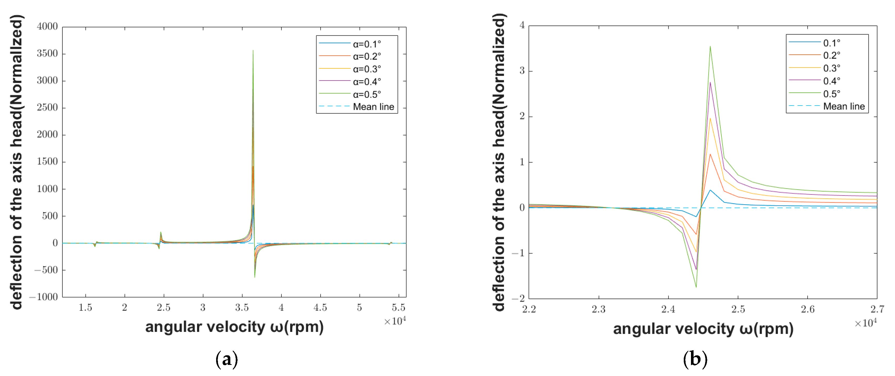
Assuming that the inclination angles are 0.1–0.5°, the section de-flection and rotation angle of different initial ends can be obtained under different angular velocities. Within the whole specified rotating speed, when the spindle inclines, the deflection of the spindle initial end is shown in Figure 9a. Around the second-order critical rotating speed, the spindle inclination fault influence on the deflection of the spindle initial end when the spindle incline at different inclination angles is shown in the schematic diagram, Figure 9b.
As can be seen from Figure 9a, the deflection of the initial spindle end increases gradually at first when the spindle inclination fault occurs, then the deflection suddenly changes direction and increases gradually along this direction, when approaching the first-order critical speed. At the first-order critical speed, the deflection decreases suddenly. Until the deflection equals zero, the deflection increases gradually along the opposite direction. The same characteristics are shown at the second-order and fourth-order critical speeds. However, at the fourth-order critical speed, the local maximum is smaller than it is at the second-order critical speed. Differently, when the rotational speed reaches the third-order critical speed, the deflection suddenly jumps to the maximum value in the upward direction. Then the direction suddenly changes, and decreases gradually.
As shown in Figure 9b, the bigger the angle, the higher the deflection of the spindle initial end. However, the changing trend of the motorized spindle initial end deflection is the same at different angles. That is to say, in the case of spindle inclination fault at the small angle, the inclination angle only changes the size of the deflection, but does not influence the trend of the deflection changing with the rotating speed.
As shown in Figure 10a, different from the unbalanced mass fault, the spindle inclination fault affects the whole motorized spindle around the first-order critical speed, while with the increase in the speed, the influence of the spindle inclination fault on the spindle initial end begins to be greater than that on the middle part of the spindle, around the second-order and third-order critical speed. In the third order, the influence on the spindle initial end reaches the maximum value. After the speed continues to increase, the influence of fault on the motorized spindle begins to increase. At the fourth-order critical speed, the deflection of the spindle end directly shows an up direction and the other end shows a down direction. Although the deflection at this time is small, if we do not pay attention to this situation, the spindle inclination fault may further develop into a membrane collision fault, which will cause serious damage to the motorized spindle.
The vibration mode of the motorized spindle under spindle inclination fault is further analyzed around the first-order critical speed, as shown in Figure 10b. Before reaching the first-order critical speed, the spindle deflection is downward, and the middle part of the spindle deflection is greater than the spindle end. Therefore, the motorized spindle is a concave type. However, after reaching the first-order critical speed, it is still in a concave shape, but the deflection is smaller than that before the first-order speed.
As can be seen from Figure 10a, the deflection of the spindle initial end increases gradually at first when unbalanced mass fault occurs, and reaches a local maximum when it reaches the first-order critical speed. At this time, the deflection direction of the shaft end suddenly changes. With the further increase in rotational speed, the deflection of spindle initial end continues to increase along this direction, and the direction suddenly changes again when the second-order critical rotational speed is reached. The same characteristics are shown at the third-order and fourth-order critical speeds. Moreover, the maximum value is reached at the third-order critical speed.
It can be observed that when the spindle inclination fault occurs, the dynamic characteristics of the spindle change with the increase in rotating speed. At a low-rotating speed, the influence of elastic deformation on the spindle deflection is greater than the inclination on it, while with the increase in rotating speed, the influence of inclination gradually becomes dominant.

4. Conclusions

In this work, focusing on the unbalanced mass fault and inclined axis fault, we improved the traditional WTMM. Then we used it to analyze the mode shape of motorized spindle under the fault at different rotation speeds. We also studied which part of the motorized spindle is more sensitive to the unbalanced mass fault, and the influence of different tilt angles on vibration of motorized spindle. The findings in this work will have different applications in many different types of machinery in which there are rotating cylinders, shafts, or spindles. The main conclusions are as follows:
(1)
If the unbalanced mass fault occurs, when the spindle speed is close to the first-order or second-order critical speed, the deflection at the initial end of the spindle is small; when the spindle speed is close to the fourth-order critical speed, the deflection is large. The opposite is true when the spindle inclination fault occurs. It can be seen that the motorized spindle is more sensitive at high rotating speeds when the unbalanced mass fault occurs, and it is more sensitive at low rotating speed when the spindle inclination fault occurs.
(2)
CNC machine tools are vibration systems with high stiffness, and the support system is flexible or nearly flexible. The rotor may exhibit rigid behavior, manifested as a smaller rotor vibration and larger bearing seat vibration. So, regardless of whether the spindle has an unbalanced mass fault or spindle inclination fault, when the spindle speed reaches the third-order critical speed, the deflection at the initial end of the spindle is the largest.
(3)
When the spindle speed approaches the first-order critical speed, an unbalanced mass fault will make the middle part of the spindle bend upward, while the spindle inclination fault will make the middle part of the spindle bend downward.
(4)
When the unbalanced mass fault occurs, the deflection will be increased first, then suddenly decrease until the direction change, and the deflection will continue to increase along this direction. When the spindle inclination fault occurs, the deflection will be increased first in the opposite direction, then gradually decreases after reaching the maximum value, and then gradually continues to increase along the original direction when it returns to the original direction.

Author Contributions

Conceptualization, S.L. and Y.W.; methodology, D.G. and Y.X.; software, Y.X.; validation, J.S.; formal analysis, D.G. and Y.X.; investigation, D.G. and Y.X.; resources, Y.W.; data curation, Y.X.; writing—original draft preparation, D.G. and Y.X.; writing—review and editing, S.L. and Y.W.; supervision, S.L. and Y.W; project administration, S.L.; funding acquisition, S.L. All authors have read and agreed to the published version of the manuscript.

Funding

This research was funded by the National Natural Science Foundation of China (No. 11802168, No. 52075310).

Institutional Review Board Statement

Not applicable.

Informed Consent Statement

Not applicable.

Data Availability Statement

The data presented in this study are available upon request from the corresponding author.

Conflicts of Interest

The authors declare no conflict of interest.

References

  1. Lin, C.-W.; Lin, Y.-K.; Chu, C.-H. Dynamic models and design of spindle-bearing systems of machine tools: A review. Int. J. Precis. Eng. Manuf. 2013, 14, 513–521. [Google Scholar] [CrossRef]
  2. Gu, D.; Wei, Y.; Xiong, B.; Liu, S.; Zhao, D.; Wang, B. Three degrees of freedom chatter stability prediction in the milling process. J. Mech. Sci. Technol. 2020, 34, 3489–3496. [Google Scholar] [CrossRef]
  3. Xiong, B.; Wei, Y.; Gu, D.; Zhao, D.; Wang, B.; Liu, S. Chatter stability analysis of variable speed milling with helix angled cutters. Proc. Inst. Mech. Eng. Part B J. Eng. Manuf. 2021, 235, 850–861. [Google Scholar] [CrossRef]
  4. Appana, D.K.; Prosvirin, A.; Kim, J.-M. Reliable fault diagnosis of bearings with varying rotational speeds using envelope spectrum and convolution neural networks. Soft Comput. 2018, 22, 6719–6729. [Google Scholar] [CrossRef]
  5. Tra, V.; Kim, J.; Kim, J.-M. Fault Diagnosis of Bearings with Variable Rotational Speeds Using Convolutional Neural Networks. In Advances in Computer Communication and Computational Sciences; Springer: Singapore, 2019; pp. 71–81. [Google Scholar]
  6. Feng, H.; Jiang, S. Dynamics of a motorized spindle supported on water-lubricated bearings. Proc. Inst. Mech. Eng. Part C J. Mech. Eng. Sci. 2017, 231, 459–472. [Google Scholar] [CrossRef]
  7. Ma, J.; Wu, L.; Zhu, Z.Q. Effect of magnet thickness on electromagnetic performance of high speed permanent magnet machines. In Proceedings of the 2017 IEEE International Electric Machines and Drives Conference (IEMDC), Miami, FL, USA, 21–24 May 2017; pp. 1–7. [Google Scholar]
  8. Wang, B.; Wei, Y.; Liu, S.; Gu, D.; Zhao, D. Intelligent chatter detection for CNC machine based on RFE multi-feature selection strategy. Meas. Sci. Technol. 2021, 32, 095904. [Google Scholar] [CrossRef]
  9. Shan, W.; Chen, X.; He, Y.; Zhou, J. A novel experimental research on vibration characteristics of the running high-speed motorized spindles. J. Mech. Sci. Technol. 2013, 27, 2245–2252. [Google Scholar] [CrossRef]
  10. Fan, K.; Xiao, J.; Wang, R.; Gao, R. Thermoelectric-based cooling system for high-speed motorized spindle I: Design and control mechanism. Int. J. Adv. Manuf. Technol. 2022, 121, 3787–3800. [Google Scholar] [CrossRef]
  11. Wang, N.; Jiang, D. Vibration response characteristics of a dual-rotor with unbalance-misalignment coupling faults: Theoretical analysis and experimental study. Mech. Mach. Theory 2018, 125, 207–219. [Google Scholar] [CrossRef]
  12. Xu, X.; Han, Q.; Chu, F. Nonlinear vibration of a generator rotor with unbalanced magnetic pull considering both dynamic and static eccentricities. Arch. Appl. Mech. 2016, 86, 1521–1536. [Google Scholar] [CrossRef]
  13. Liu, H.; Wu, Y.; Wang, X.; Yan, P.; Zhang, X. Nonlinear normal modes and primary resonance for permanent magnet synchronous motors with a nonlinear restoring force and an unbalanced magnetic pull. Nonlinear Dyn. 2019, 97, 1197–1213. [Google Scholar] [CrossRef]
  14. Werner, U. Influence of electromagnetic field damping on forced vibrations of induction rotors caused by dynamic rotor eccentricity. ZAMM—J. Appl. Math. Mech./Z. Für Angew. Math. Und Mech. 2017, 97, 38–59. [Google Scholar] [CrossRef]
  15. Zuo, S.; Li, D.; Mao, Y.; Deng, W. Longitudinal vibration analysis and suppression of electric wheel system driven by in-wheel motor considering unbalanced magnetic pull. Proc. Inst. Mech. Eng. Part D J. Automob. Eng. 2019, 233, 2729–2745. [Google Scholar] [CrossRef]
  16. Xiang, C.; Liu, F.; Liu, H.; Han, L.; Zhang, X. Nonlinear dynamic behaviors of permanent magnet synchronous motors in electric vehicles caused by unbalanced magnetic pull. J. Sound Vib. 2016, 371, 277–294. [Google Scholar] [CrossRef]
  17. Kumar, G.; Kalita, K. Vibration control using BCW induction motor. Procedia Eng. 2016, 144, 94–101. [Google Scholar] [CrossRef]
  18. Bossmanns, B.; Tu, J.F. A power flow model for high speed motorized spindles—Heat generation characterization. J. Manuf. Sci. Eng. 2000, 123, 494–505. [Google Scholar] [CrossRef]
  19. Li, H.; Shin, Y.C. Integrated dynamic thermo-mechanical modeling of high speed spindles, Part 1: Model development. J. Manuf. Sci. Eng. 2004, 126, 148–158. [Google Scholar] [CrossRef]
  20. Li, H.; Shin, Y.C. Integrated dynamic thermo-mechanical modeling of high speed spindles, Part 2: Solution procedure and validations. J. Manuf. Sci. Eng. 2004, 126, 159–168. [Google Scholar] [CrossRef]
  21. Xul, J.; Zheng, X.; Zhang, J.; Liu, X. Vibration characteristics of unbalance response for motorized spindle system. Procedia Eng. 2017, 174, 331–340. [Google Scholar] [CrossRef]
  22. Liu, J.; Lai, T.; Chen, X. Dynamics analysis of unbalanced motorized spindles supported on ball bearings. Shock Vib. 2016, 2016, 2787524. [Google Scholar] [CrossRef]
  23. Su, X.; Lu, H.; Zhang, X.; Fan, W.; Zhang, Y. Analysis of dynamic characteristic for misalignment-spline gear shaft based on whole transfer matrix method. J. Vibroeng. 2018, 20, 1392–1408. [Google Scholar] [CrossRef]
  24. Huang, S.; Chi, X.; Xu, Y.; Sun, Y. Dynamic characteristics of coupling shaft system in tufting machine based on the Riccati whole transfer matrix method. Proc. Inst. Mech. Eng. Part C J. Mech. Eng. Sci. 2017, 231, 356–371. [Google Scholar] [CrossRef]
  25. Jiang, S.; Zheng, S. A modeling approach for analysis and improvement of spindle-drawbar-bearing assembly dynamics. Int. J. Mach. Tools Manuf. 2010, 50, 131–142. [Google Scholar] [CrossRef]
  26. Zhong, Y.; He, Y.; Wang, Z.; Li, F. Rotor Dynamics; Tsinghua University Press: Beijing, China, 1987. [Google Scholar]
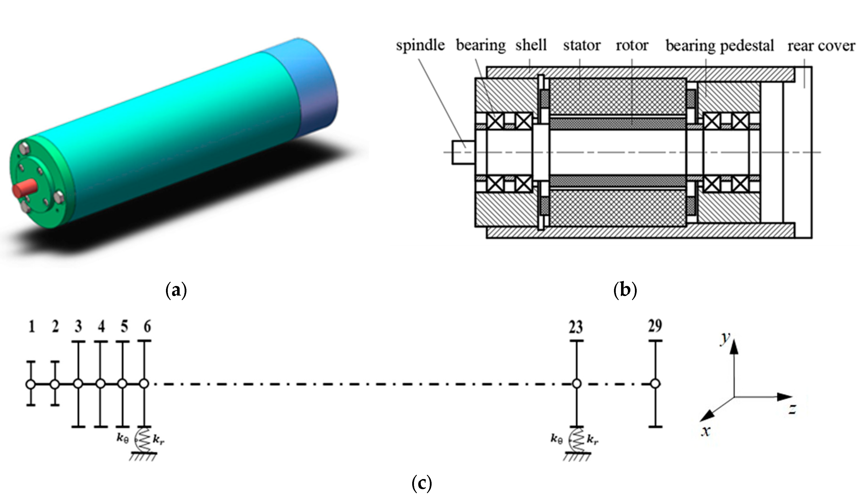
Figure 1. Schematic diagram of high-speed motorized spindle: (a) description of what is contained in the first panel; (b) structure of motorized spindle; (c) lumped mass model of high-speed motorized spindle.
Applsci 13 10053 g001
Figure 2. Stress diagram of unit: (a) stress diagram of unit; (b) stress diagram of massless elastic shaft.
Applsci 13 10053 g002
Figure 3. Stress diagram of rigid disc under unbalanced mass fault.
Applsci 13 10053 g003
Figure 4. Stress diagram of massless elastic shaft under spindle inclination fault.
Applsci 13 10053 g004
Figure 5. Δω − ω curve.
Applsci 13 10053 g005
Figure 6. The first fourth-order mode shapes of the motorized spindle: (a) first-order mode shape; (b) second-order mode shape; (c) third-order mode shape; (d) fourth-order mode shape.
Applsci 13 10053 g006aApplsci 13 10053 g006b
Figure 7. Deflection of the spindle initial end in the case of unbalanced mass fault: (a) deflection of the spindle initial end; (b) spindle initial end deflection when fault occurs at different units.
Applsci 13 10053 g007
Figure 8. Mode shape in the case of unbalanced mass fault: (a) mode shape in working speed range; (b) mode shape around the first-order critical speed.
Applsci 13 10053 g008
Figure 9. Deflection of the spindle initial end in the case of spindle inclination fault: (a) deflection of the spindle initial end; (b) spindle intimal end deflection when fault occurs at different inclinations.
Applsci 13 10053 g009
Figure 10. Mode shape in the case of spindle inclination fault: (a) mode shape in working speed range; (b) mode shape around the first-order critical speed.
Applsci 13 10053 g010
Table 1. Parameters of high-speed motorized spindle.
ParameterValue
Spindle length/mm290
Mass/kg9.87
Current/A10
Inner diameter of motor rotor/mm42
Outer diameter of rotating spindle/mm40
Outer diameter of motor rotor/mm100
Type of bearing71,908 CE/HCP4A
Maximum speed/rpm58,000
Disclaimer/Publisher’s Note: The statements, opinions and data contained in all publications are solely those of the individual author(s) and contributor(s) and not of MDPI and/or the editor(s). MDPI and/or the editor(s) disclaim responsibility for any injury to people or property resulting from any ideas, methods, instructions or products referred to in the content.