Abstract
If an unexpected vibration or force is expected to be generated during operation, a vibration mount must be installed beneath the support system. A mass-block can be considered to reduce the structure basement fundamental frequency of the basement. Thus, the efficiency of a single-mount or mass-block can be enhanced by implementing a single-mount module called a mass-block integrated mount module (MIMM). This study addressed the tuning process of multiple mount modules in a supported system by evaluating the mount module using the proposed total performance index, building on a previous evaluation method comprising the first and second performance indices. This index was subsequently applied to assess the control capability of MIMM concerning both the self-excitation of an electric power plant and basement input. The extended 3-degrees-of-freedom (3-d.o.f.) electric power generator model was applied to determine the best selection of the mechanical properties for the MIMM over the various mechanical parameter settings (ranging between 10 and 1000% of the original parameters) of the two sub-mounts. The simulation results demonstrate a reduction in the total performance index from 8.2, as calculated in a previous study, to 0.2. The novelty of the optimal MIMM conditions is confirmed by the simultaneous enhancement of both performance indices.
1. Introduction
The mount module is widely used as an anti-vibration device, and several applications are possible with different mechanisms. A passive-type mount is typically a simple structure that is easily installed in mechanical systems and is cost- and maintenance-free [1,2,3,4,5,6]. The mechanical properties related to the pass type are deterministic and impossible to revise under operational conditions. Therefore, the original selection of mechanical elements, such as springs and dampers, is critical for maximizing the anti-vibration capacity. An active-type mount module is advantageous for controlling the mechanical properties as much as possible for different operational conditions, or supporting payloads such that optimal vibration control can be achieved using an efficient control strategy [7,8,9,10]. However, the primary concern for the active-type mount is the fail-safe solution or rigorous system identification, including the actuating mount itself [11,12,13,14,15,16]. The increasing cost of installation or monitoring systems is another hurdle for popular applications.
Recently, the concept of quasi-zero stiffness has been effectively implemented in vibration isolation practices. This approach has been thoroughly explained in a comprehensive review paper [17] that covers a wide range of isolator types, from passive to semi/active solutions. Furthermore, several innovative mount module concepts have been proposed to control the vibrations of supporting systems. Several novel vibration mount concepts have been proposed by numerous researchers. Ling et al. proposed using a thick-walled ring spring for metro superstructures. Accordingly, they attained considerable dynamic response control over the vertical acceleration of three-dimensional structures from the numerical simulation results [18]. Yang et al. examined the dynamic characteristics of a post-buckling silicone gel column in the low-frequency range and verified them experimentally [19]. Huang et al. stated the dynamic characteristics of a post-buckling silicone gel column and then conducted a multi-parameter optimization technique for effective vibration isolation [20]. Choi at el. analyzed a proposed adaptive magnetorheological elastomer-based vibration absorber designed for high-frequency excitations and verified this design with experimental results [21]. Fang at el. proposed precision instrument vibration isolation platforms intended to manage horizontal road vibrations during vehicle operation and validated their accuracy using on-site measurement results [22].
The mechanical structure of a mount module can be formulated using the stiffness and viscous damping coefficients. A mass block can be integrated with a sub-mount in the mount module. A mass block beneath the supporting structure increases the total mass of the basement structure such that the first resonance frequency of the basement decreases to a low-frequency point. A coil spring or other mechanical components, such as a hydraulic or air suspension, can be used to represent the stiffness coefficient, and comparable mechanical devices can be used to produce viscous damping. Alternatively, the viscous damping coefficient can be derived from the high-damping material itself, such as rubber or engineering plastic. Therefore, the mount module can be formulated with several sub-mounts, both spring and damper, and the mass block can be integrated with sub-mounts [23]. This type of mount module is defined as a mass-block integrated mount module (MIMM).
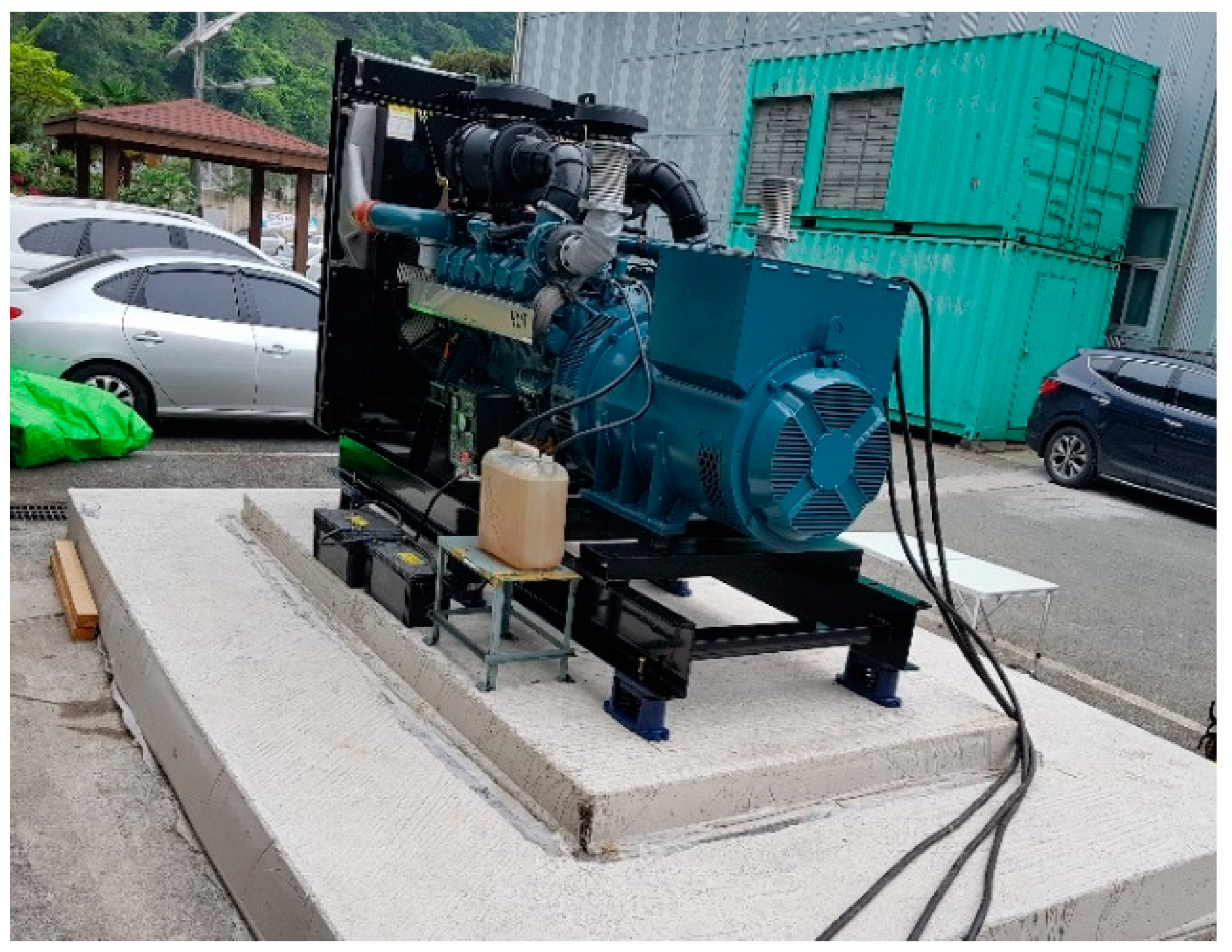
An electric power plant manufactured by the DAEHUNG Electric Machinery Company in South Korea was selected as an example for the modeling of a supported system. The electric power plant was set to generate 750 kW, using a V-type 12-cylinder combustion engine, and operate at a rated speed of 1800 rev/min [23]. The configuration of the overall electric power plant is illustrated in Figure 1.
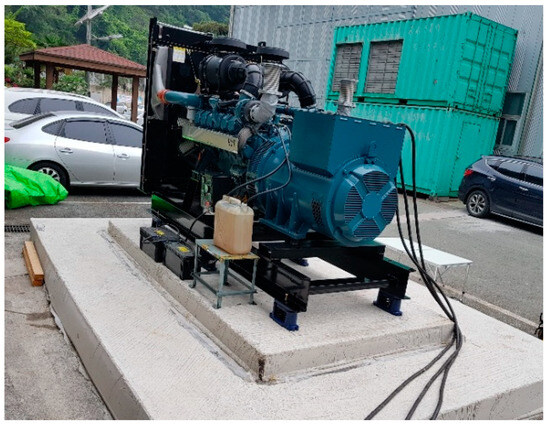
Figure 1.
Configuration of 750 kW electric power plant [23].
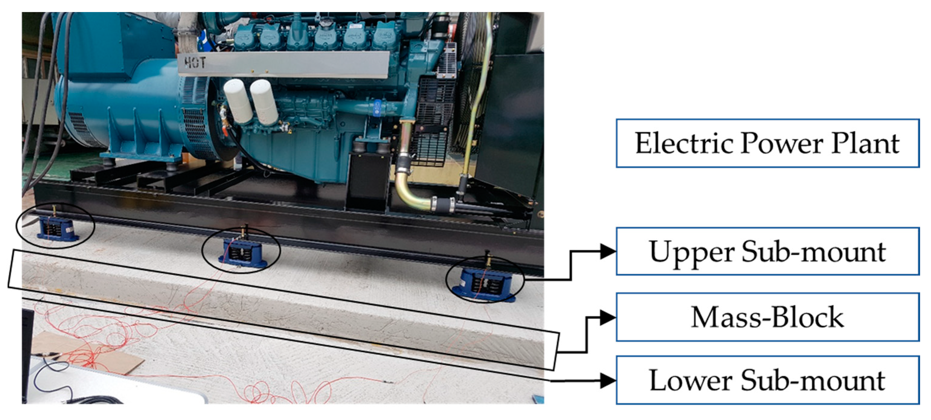
The primary components of the MIMM consist of three parts: six upper sub-mounts, one mass block, and a lower sub-mount. The six upper sub-mounts supported the static load of the electric power plant and the dynamic loads for external excitations by allocating them at evenly spaced locations. Electric rubber pads were used as lower sub-mounts, which isolated the mass blocks from the basement structure. The overall configuration of MIMM is shown in Figure 2.
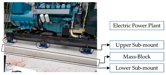
Figure 2.
Main components of MIMM of electric power plant.
System modeling is a methodology that can reasonably analyze the behavior of a complex system and predict responses under certain conditions by expressing the behavior in an engineered representative formula. Therefore, system-modeling techniques have been used in various engineering studies. If the anti-isolator module is complex, the system modeling technique is appropriate, even when it is difficult to determine which parameters of the mount module should be changed to achieve the desired performance. The system to be supported can be simply expressed as a concentrated mass or rigid body, and the target MIMM must be expressed as a sub-component in as much detail as possible. In this study, the sub-mounts located above and below the mass block were modeled with variable coefficients of the spring and damper elements. All variable coefficients were selected as the target parameters for the MIMM optimization.
This study is an extension of a previous study, which partially focused on the optimal selection of the mechanical properties of the lower sub-mount under the assumption of a fixed mechanical property of the upper sub-mount [24]. The system model of an electric power plant was revised by incorporating variable coefficients within the two sub-mounts, rendering the proposed model suitable for MIMM optimization. Therefore, the array of potential modification cases encompassed all sub-mount types within the MIMM setup, enabling us to collect simulation results for an advanced tuning process of the mechanical properties within MIMM. The total performance index is introduced based on the preceding evaluation method, comprising the first and second performance indices. This index was subsequently applied to assess the control capability of the MIMM with respect to both the self-excitation of an electric power plant and basement input. Considering all the mechanical properties of the sub-mounts in the MIMM as the target parameters, the best choice of mechanical parameters can be derived from the two performance indices of the MIMM via the theoretical 3-d.o.f. system model. The optimal tuning case of sub-mounts was valid for the frequency range of interest between 1 and 120 Hz, and the optimum solution was the compromised strategy of the two excitations, self-excitation in the system, and basement input.
2. Evaluation Strategy for MIMM at Electric Power Generator
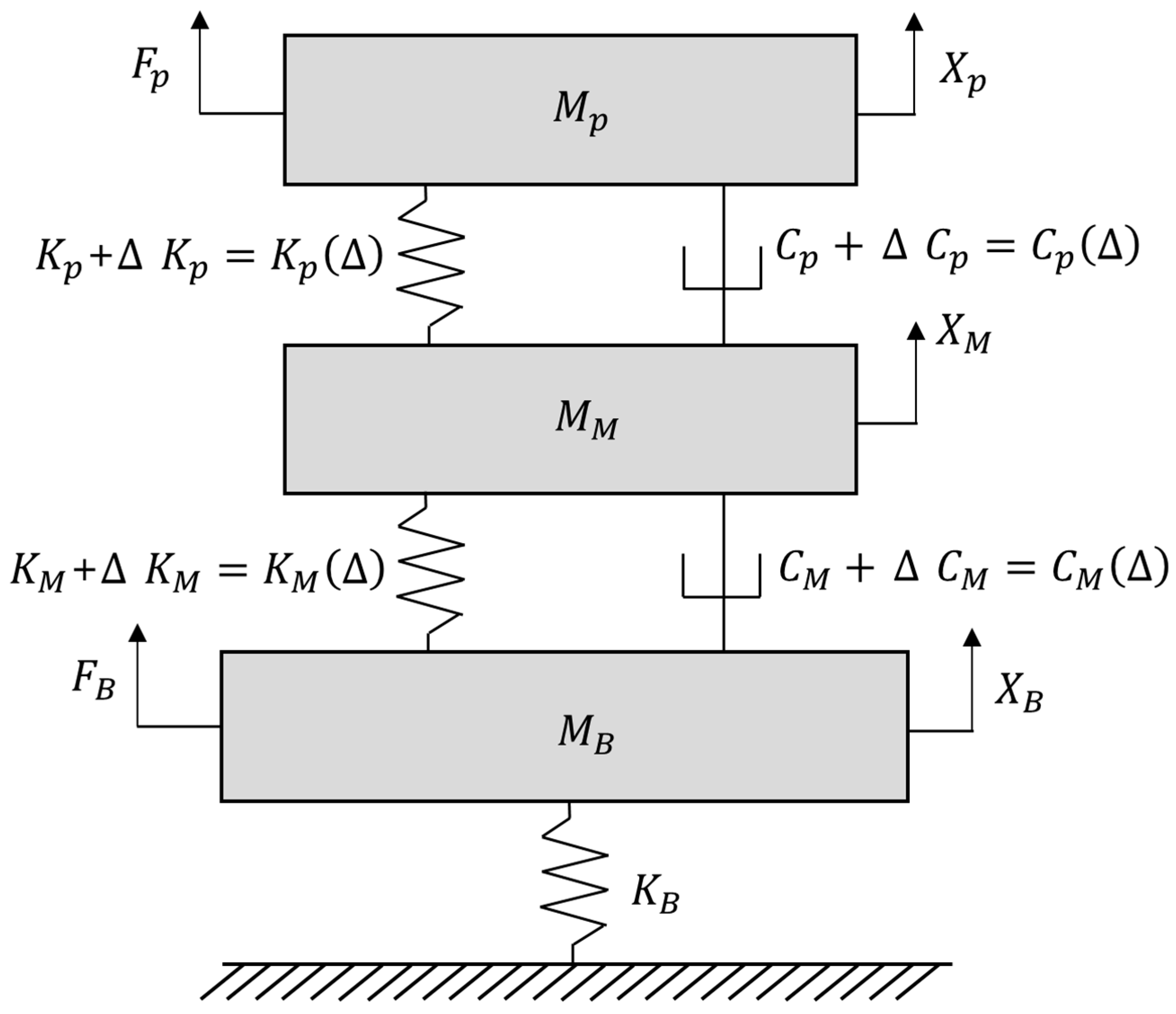
The electric power plant was developed using a 3-d.o.f. system including the MIMM. The original system model was consistent with those developed in previous studies [23,24]. However, the target system model is an extended version derived from the original by incorporating variable stiffness and damping coefficients in both the upper and lower sub-mounts, as illustrated in Figure 1. The electric power plant, mass block, and surrounding building were modeled as concentrated masses , , and , respectively. The connecting element between the electric power plant and the mass block was expressed by the upper sub-mount (spring , damper ), and the lower sub-mount was placed between the mass block and surrounding building by spring and damper , respectively. The variations in the connecting element were indicated by the symbol ; for example, is the adjusted coefficient obtained by adding to . A low stiffness value for was chosen to prevent the building system dynamics from affecting the MIMM. In addition, self-excitation from the electric power plant was assigned at and the basement input from the surrounding building was set for , respectively. The theoretical model of an electric power plant supported by the MIMM is illustrated in Figure 3.
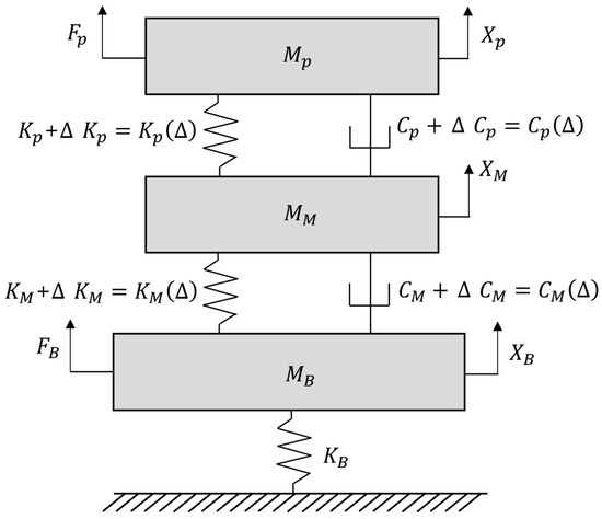
Figure 3.
Equivalent electric power generator model supported by vibration isolators.
The theoretical model for the supported power generator in Figure 3 can be expressed as a linear formula because all connecting elements consist of linear connecting elements: the stiffness coefficient is proportional to the displacement and the damping coefficient is proportional to the velocity. Based on an earlier study [24], the governing equations are expressed as Equations (1)–(3). The displacements of the three concentrated masses , , and , were denoted by , , and , respectively.
The original system model parameters listed in Table 1 were determined experimentally based on the required characteristics of the system. The mechanical properties of the upper sub-mount (spring , damper ) were measured using elastomer testing equipment (835 model/MTS systems, Eden Prairie, Minnesota, United States). The mechanical properties of the lower sub-mount (spring , damper ) were adjusted from the values of the upper sub-mount, and two masses (, ) were obtained using simple measurements. The mechanical properties (, ) of the surrounding buildings were selected as rigid bodies with low resonance frequencies in the frequency range 1–120 Hz. The experimental frequency response function between the target electric power plant and the mass block was used to update the constructed 3-d.o.f. model in Figure 3, and the detailed selection of the system parameters is explained in an earlier study [23]. A summary of the current system model is listed in Table 1.

Table 1.
Specifications of the theoretical power plant model [23].
The solution for the three displacement variables can be effectively obtained through Fourier transforms, therein the variable ‘s’ is substituted with ‘’ in the Equations (1)–(3) originally formulated in the Laplace domain. Two performance indices developed in earlier studies [23,24] were reused. The first and second performance indices are related to the self-excitation of the basement input, as shown in Equations (4) and (5), respectively. The first and second performance indices represent the transmissibility of the response from an electric power plant to a building and that from a mass block to an electric power plant, respectively. Both indices indicated effective performances when the response decreased as it passed through the MIMM. Therefore, the first and second performances were associated with the vibration control capability for self-excitation at the power plant and input from the basement, respectively. Here, ‘s’ denotes the s-domain Laplace transformation, and three variables in Equation (6), which simplified two performance indices, were derived from the governing Equations (1)–(3) [25,26]. In addition, is the absolute value of the complex value .
The selection of all mechanical properties of the MIMM and the upper and lower sub-mounts can be evaluated using the two performance indices, and it is best to satisfy the minimum value of the two indices simultaneously. Therefore, the optimal case in the MIMM can be effectively determined by comparing the two calculated performance indices among the candidate mechanical properties of the two sub-mounts.
3. Evaluation of Mechanical Properties of Two Sub-Mounts in MIMM
The variations in MIMM are possible with two of the four parameters: and for the upper sub-mount and and for the lower sub-mount. There may be several possible candidates for the four parameters, and 16 cases is the lowest number of cases needed to investigate the influence of each parameter on the performance of MIMM by increasing the parameter 10 times or decreasing it 10 times from the original listed in Table 1. The scheduled simulation cases are listed in Table 2. Here, the four cases (I–IV) are variations in each parameter of the upper sub-mount, and the sub-cases ((a)–(d)) in each case denote the variations in each parameter of the lower sub-mount.

Table 2.
Simulation candidate cases of MIMM.
The frequency of interest was precisely divided into two parts: 30–120 Hz for the upper sub-mount and 1–60 Hz for the lower sub-mount. For the upper sub-mount, the operating rotating speed of the electric power plant was set to 1800 rev/min, such that the MIMM was required to control the self-excitation between 30 (first order) and 120 Hz (fourth order). In contrast, basement excitation was limited to 120 Hz because the ambient seismic wave field has been reported to range from 0.001 to 100 Hz [27]. Therefore, the first performance index ( in Equation (4)) was calculated to be between 30 and 120 Hz, and the second performance index ( in Equation (5)) was calculated to be between 1 and 120 Hz. The variations in the performance index over the candidate cases in Table 2 are expressed by the ratio of the performance indices ( and ), and the calculated result was divided by the original result as shown below, where and are the first and second performance indices, respectively, as calculated from the original conditions in Table 1.
Both ratios of the performance index indicate that a high performance of the MIMM over the responsible excitation can be attained with a small value for all frequencies of interest, such that another indicator () can be introduced by multiplying the two ratios of the performance index. The performance indices or related ratio expressions can be calculated in a frequency range and frequency variable, Hz, and can be used to represent as expressed in Equation (9).
The multiplication of the two ratios of the performance index is valid for 30–120 Hz because the first performance index is between 30 and 120 Hz. Therefore, the MIMM can be evaluated from the total performance index () by considering the effective frequency range in Equation (10).
The total index was calculated for the sixteen candidates listed in Table 2, and the simulation results are summarized in Table 3.

Table 3.
Simulation results for sixteen cases.
All four cases (Cases I–IV) covered the variations in the upper sub-mount, and Case I was selected as the best case. These results indicate that both the small stiffness and damping coefficient of the upper sub-mount are suitable for the MIMM. In contrast, all four cases (Cases (a) to (d)) covered the variations in the lower sub-mount, and both Case (c) and (d) were the best cases. These results indicate that the high stiffness of the lower sub-mount is a critical condition for an enhanced MIMM, with little influence on the damping coefficient. Two aspects of the simulation results revealed that the optimal condition of the MIMM is a combination of two sub-mounts: a small stiffness and damping coefficient of the upper sub-mount, and a high stiffness coefficient of the lower sub-mount. The imbalance of two different terms in Equation (10) is a cause for concern because may be either greater or smaller than the other summation term, distorting the results from Equation (10). The summary in Table 4 represents the calculation result without considering

Table 4.
Simulation results for sixteen cases ignoring .
The rank of the simulation results in Table 4 was comparable to those in Table 3, indicating that the influence of on the current MIMM was minimal. However, the formulation in Equation (10) is still valuable because other MIMM cases may be sensitive to the low-frequency range under different specifications of the system parameters.
Both the small stiffness and damping coefficient of the upper sub-mount (Case I) lead to a loose mechanical connection between the responsible power plant and the mass block, such that any excitation power transfer between them can be efficiently prevented. Therefore, the current optimal result from the upper sub-mount is a reasonable solution for both types of excitations. In the case of high-stiffness conditions, Case I-(c) and -(d), the original stiffness is much higher than the stiffness such that the two masses, and , behave as a rigid body compared to the target electric power plant . In addition, was more than ten times larger than and . Therefore, the optimal cases, Cases I-(c) and-(d), can be assumed to be two 2-d.o.f. system models with a small mass and a large mass + with a loose connection (small stiffness and damping coefficient) between them.
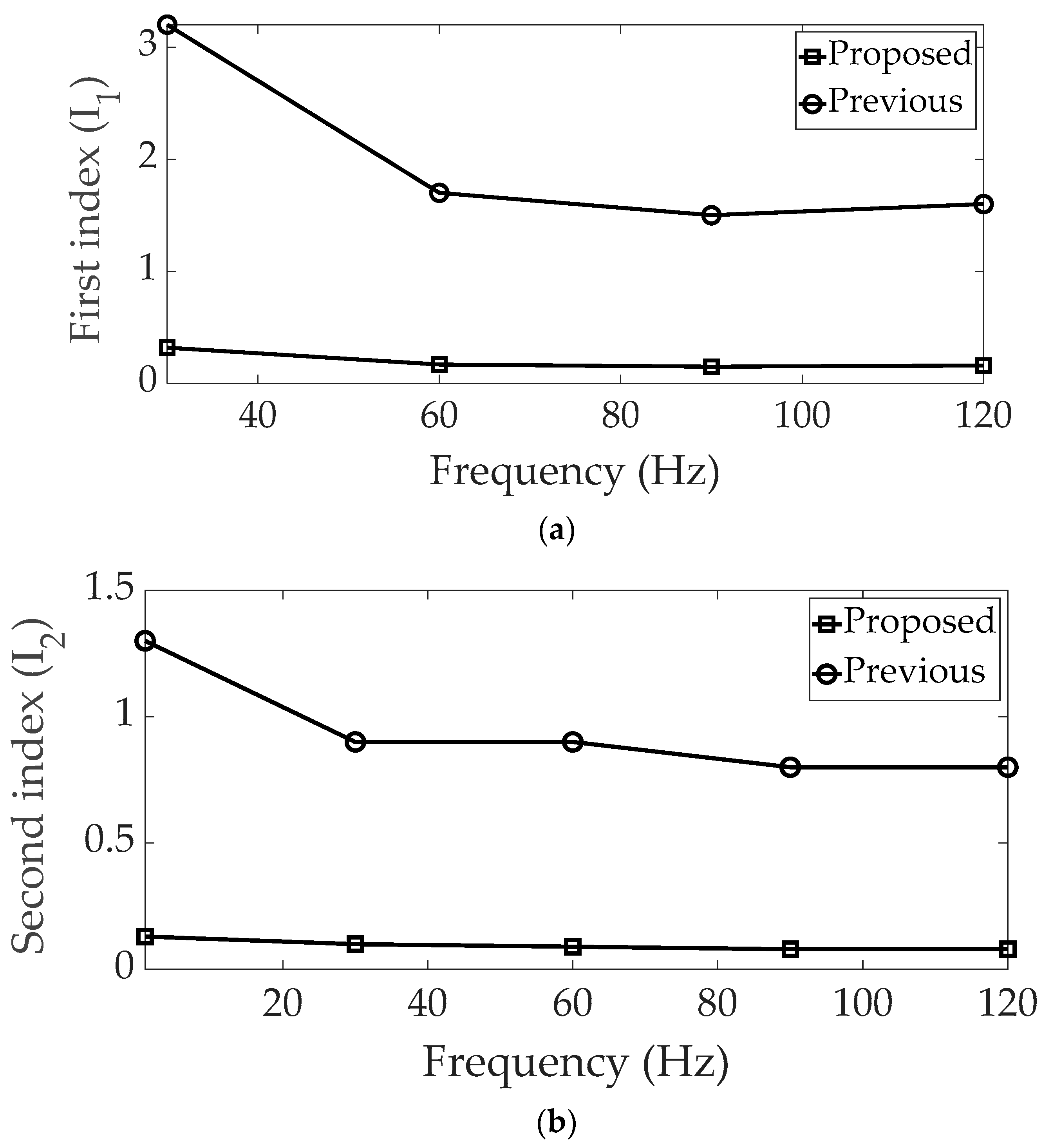
This result differed from that reported in an earlier study [24]. The complete performance indices are summarized in Table 5, and two performance indices (first and second) are shown in Figure 4. The proposed method can significantly decrease the performance indices by simultaneously assigning two sub-mounts instead of the restricted lower sub-mount scenario. Based on the optimization results derived from the suggested method, all index values were below one, underlining the potential for efficient vibration control using the MIMM across the entire frequency range of interest.

Table 5.
Comparison of the total performance indices for two optimization cases.
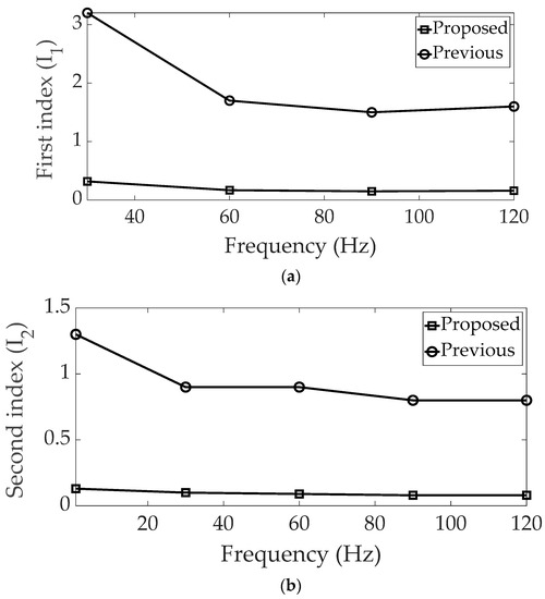
Figure 4.
Comparison of the performance indices: (a) first, (b) second.
Under the same evaluation criterion with two performance indices, increasing the stiffness coefficient, and decreasing the damping coefficient (equivalent to Case II), is best for the lower sub-mount with fixed mechanical properties in the upper sub-mount. The best condition of the lower sub-mount was changed to Case I, considering the variations in the mechanical properties of the upper sub-mount. The calculation of the total performance index decreased considerably when the mechanical properties of the upper sub-mount were adjusted, as listed in Table 2. Therefore, the partial optimum of the MIMM cannot guarantee the global optimum of the MIMM, such that the total tuning of mechanical properties in sub-mounts can achieve the reliable control of vibrations from two different excitation conditions. Hence, the design guidelines for the MIMM can be summarized as follows: First, the stiffness and damping coefficients of the upper sub-mount should be kept low to hinder the transfer of excitation between the supporting system and mass block. Moreover, the static stiffness of the upper sub-mount should be sufficiently robust to uphold the heavy-weight target system at an appropriate height. Second, the stiffness coefficient of the lower sub-mount should be increased without any limitations on the damper characteristics. Generally, elastomers or rubber materials are employed to isolate the mass block from the structure at the floor level with a high stiffness coefficient, which is crucial for the selection of an appropriate lower sub-mount. Third, a simulation was conducted for the supporting system, ensuring that there was no resonance frequency within the frequency range of interest (1–120 Hz). Consequently, the optimal states of the two sub-mounts in the MIMM configuration may be effective in analogous dynamic scenarios.
However, the best choice of mechanical properties cannot be determined from the simulation results of the 16 cases reported in Table 2 because the selected simulation cases were increased or decreased 10 times from the measured original mechanical properties. Therefore, the fine-tuning of the two sub-mounts used in the MIMM can be derived from additional case studies that will be conducted in the near future. Furthermore, it is crucial to authenticate the optimal MIMM case to validate the feasibility of the improved mechanical property combination considering the experimental implications. However, achieving an ideal increase or decrease in each distinct sub-component is unattainable owing to the constraints of the experimental setup. Thus, the experimental arrangement should be validated to encompass practically attainable modifications in the mechanical properties of the MIMM.
4. Conclusions
The optimal selection of the MIMM was conducted to simulate a 3-d.o.f. model of an electric power plant by considering 16 cases with different combinations of the two sub-mounts. The frequency range of interest was established as 1–120 Hz, considering the operational requirements of the power plant and potential input from basement earthquakes. All system parameters within the original configuration were validated through experiments conducted in a previous study. To determine the optimal MIMM scenario, an extended 3-degree-of-freedom (3-d.o.f.) model was employed considering the variations in the mechanical parameters of the two sub-mounts. The mechanical properties of the MIMM were evaluated using a total performance index, which is a newly proposed criterion that combines two performance indices. The best case for the MIMM was determined by decreasing both the stiffness and damping coefficients in the upper sub-mount and increasing the stiffness coefficient in the lower sub-mount, which corresponds to Cases I-(c) and (d). By referring to an earlier study, the optimal condition for the lower bubble mount was changed to Case I from Case II, and a considerable reduction in the total performance index was achieved by increasing the stiffness in the lower sub-mount. The total performance index, which was 8.2 in a previous study, was significantly reduced to 0.2 using the proposed method. This outcome suggests that the optimal MIMM scenario can be achieved by implementing the proposed comprehensive variations in both sub-mounts simultaneously, rather than relying on partial variations in the lower sub-mount alone. Another novelty lies in the simultaneous improvement of the two performance indices, with both indices reflecting the performance of the MIMM under two different excitation conditions. Therefore, the optimal selection of mechanical properties aims to strike a balance in controlling vibration transfer for both excitation situations.
Author Contributions
Conceptualization, formal analysis, software, investigation, C.K.; validation, writing of the original draft, visualization, C.-J.K. All authors have read and agreed to the published version of the manuscript.
Funding
This research was funded by the Ministry of SMEs and Startups of South Korea (Grant No. 1425172735).
Institutional Review Board Statement
Not applicable.
Informed Consent Statement
Not applicable.
Data Availability Statement
The data presented in this study are available upon request from the corresponding author.
Acknowledgments
This research was supported by the Pukyong National University.
Conflicts of Interest
The authors declare no conflict of interest.
References
- Alujevic, N.; Cakmak, D.; Wolf, H.; Jokic, M. Passive and active vibration isolation system using inerter. J. Sound Vib. 2018, 418, 163–183. [Google Scholar] [CrossRef]
- Siami, A.; Karimi, H.R.; Cigada, A.; Zappa, E.; Sabbioni, E. Parameter optimization of an inerter-based isolator for passive vibration control of Michelangelo’s Rondanini Pieta. Mech. Syst. Signal Process. 2018, 98, 667–683. [Google Scholar] [CrossRef]
- Wu, Z.; Jing, X.; Sun, B.; Li, F. A 6DOF passive vibration isolator using X-shape supporting structures. J. Sound Vib. 2016, 380, 90–111. [Google Scholar] [CrossRef]
- Lee, J.; Okwudire, C.E. Reduction of vibrations of passively-isolated ultra-precision manufacturing machines using mode coupling. Precis. Eng. 2016, 43, 164–177. [Google Scholar] [CrossRef]
- Ribeiro, E.A.; Lopes, E.M.O.; Bavastri, C.A. A numerical and experimental study on optimal design of multi-DOF viscoelastic supports for passive vibration control in rotating machinery. J. Sound Vib. 2017, 411, 346–361. [Google Scholar] [CrossRef]
- Oh, H.U.; Lee, K.J.; Jo, M.S. A passive launch and on-orbit vibration isolation system for the spaceborne cryocooler. Aerosp. Sci. Technol. 2013, 28, 324–331. [Google Scholar] [CrossRef]
- Gu, X.; Yu, Y.; Li, J.; Li, Y. Semi-active control of magnetorheological elastomer base isolation system utilizing learning-based inverse model. J. Sound Vib. 2017, 406, 346–362. [Google Scholar] [CrossRef]
- Santos, M.B.; Coelho, H.T.; Neto, F.P.L.; Mafhoud, J. Assessment of semi-active friction dampers. Mech. Syst. Signal Process. 2017, 94, 33–56. [Google Scholar] [CrossRef]
- Oh, H.U.; Choi, Y.J. Enhancement of pointing performance by semi-active variable damping isolator with strategies for attenuating chattering effects. Sens. Actuators A Phys. 2011, 165, 385–391. [Google Scholar] [CrossRef]
- Azadi, M.; Behzadipour, S.; Faulkner, G. Performance analysis of a semi-active mount made by a new variable stiffness spring. J. Sound Vib. 2011, 330, 2733–2746. [Google Scholar] [CrossRef]
- Pingzhang, Z.; Jianbin, D.; Zhenhua, L. Simultaneous topology optimization of supporting structure and loci of isolators in an active vibration isolation system. Comput. Struct. 2018, 194, 74–85. [Google Scholar]
- Beijen, M.A.; Tjepkema, D.; Dijk, J. Two-sensor control in active vibration isolation using hard mounts. Control Eng. Pract. 2014, 26, 82–90. [Google Scholar] [CrossRef]
- Yang, X.L.; Wu, H.T.; Li, Y.; Chen, B. Dynamic isotropic design and decentralized active control of a six-axis vibration isolator via Stewart platform. Mech. Mach. Theory 2017, 117, 244–252. [Google Scholar] [CrossRef]
- Wang, Z.; Mak, C.M. Application of a movable active vibration control system on a floating raft. J. Sound Vib. 2018, 414, 233–244. [Google Scholar] [CrossRef]
- Li, Y.; He, L.; Shuai, C.G.; Wang, C.Y. Improved hybrid isolator with maglev actuator integrated in air spring for active-passive isolation of ship machinery vibration. J. Sound Vib. 2017, 407, 226–239. [Google Scholar] [CrossRef]
- Chi, W.; Cao, D.; Wang, D.; Tang, J.; Nie, Y.; Huang, W. Design and experimental study of a VCM-based stewart parallel mechanism used for active vibration isolation. Energies 2015, 8, 8001–8019. [Google Scholar] [CrossRef]
- Ma, Z.; Zhou, R.; Yang, Q. Recent Advances in Quasi-Zero Stiffness Vibration Isolation Systems: An Overview and Future Possibilities. Machines 2022, 10, 813. [Google Scholar] [CrossRef]
- Ling, Y.; Wu, S.; Gu, J.; Lai, H. A Novel Ring Spring Vibration Isolator for Metro Superstructure. Appl. Sci. 2021, 11, 8422. [Google Scholar] [CrossRef]
- Yang, J.-H.; Yang, X.-D.; Han, Q.-K.; Liu, J.-G. Post-Buckling Spring Vibration Isolator Using Silicone Gel Column: A Theoretical and Experimental Study. Appl. Sci. 2021, 11, 10559. [Google Scholar] [CrossRef]
- Huang, Z.; Shi, X.; Mu, D.; Huang, X.; Tong, W. Performance and Optimization of a Dual-Stage Vibration Isolation System Using Bio-Inspired Vibration Isolators. Appl. Sci. 2022, 12, 11387. [Google Scholar] [CrossRef]
- Choi, Y.; Wereley, N.M. Vibration Isolation Performance of an Adaptive Magnetorheological Elastomer-Based Dynamic Vibration Absorber. Actuators 2022, 11, 157. [Google Scholar] [CrossRef]
- Zhang, Y.; Wang, X.; Lu, C.; Liu, K.; Song, B. Influence of Road Traffic Vibration on Micro-Dynamic Response of Precision Instrument Vibration Isolation Platforms. Eng. Proc. 2023, 36, 48. [Google Scholar] [CrossRef]
- Kim, C.-J. Design criterion of damper component of passive-type mount module without using base mass-block. Energies 2018, 11, 1548. [Google Scholar] [CrossRef]
- Park, Y.W.; Kim, T.-W.; Kim, C.-J. Compromised vibration isolator of electric power generator considering self-excitation and basement input. Inventions 2023, 8, 40. [Google Scholar] [CrossRef]
- Rao, S.S. Mechanical Vibration, 5th ed.; Pearson: Singapore, 2011. [Google Scholar]
- Inman, D.J. Engineering Vibration, 4th ed.; Pearson: Singapore, 2013. [Google Scholar]
- Nishida, K. Ambient seismic wave field. Proc. Jpn. Acad. Ser. B Phys. Biol. Sci. 2017, 93, 423–448. [Google Scholar] [CrossRef] [PubMed]
Disclaimer/Publisher’s Note: The statements, opinions and data contained in all publications are solely those of the individual author(s) and contributor(s) and not of MDPI and/or the editor(s). MDPI and/or the editor(s) disclaim responsibility for any injury to people or property resulting from any ideas, methods, instructions or products referred to in the content. |
© 2023 by the authors. Licensee MDPI, Basel, Switzerland. This article is an open access article distributed under the terms and conditions of the Creative Commons Attribution (CC BY) license (https://creativecommons.org/licenses/by/4.0/).

