Article

A Novel Charging Station on Overhead Power Lines for Autonomous Unmanned Drones

by
Antonio-Miguel Muñoz-Gómez
1,*,
Juan-Manuel Marredo-Píriz
2,
Javier Ballestín-Fuertes
1 and
José-Francisco Sanz-Osorio
3
1
CIRCE Foundation, Parque Empresarial Dinamiza, Avenida Ranillas Edificio 3D, 50018 Zaragoza, Spain
2
CATEC Advanced Center for Aerospace Technologies, Parque Tecnológico y Aeronáutico de Andalucía, C/ Wilbur y Orville Wright 19, 41309 La Rinconada, Spain
3
Instituto Universitario de Investigación Mixto CIRCE, Universidad de Zaragoza-Fundación CIRCE, 50018 Zaragoza, Spain
*
Author to whom correspondence should be addressed.
Appl. Sci. 2023, 13(18), 10175; https://doi.org/10.3390/app131810175
Submission received: 18 July 2023 / Revised: 1 September 2023 / Accepted: 6 September 2023 / Published: 10 September 2023
(This article belongs to the Special Issue Future Autonomous Drones II)

Abstract

:
Innovative drone-based technologies provide novel techniques to guarantee the safety and quality of power supply and to perform these tasks more efficiently. Electric multirotor drones, which are at the forefront of technology, face significant flight time limitations due to battery capacity and weight constraints that limit their autonomous operation. This paper presents a novel drone charging station that harvests energy from the magnetic field present in power lines to charge the drone’s battery. This approach relies on a charging station that is easy to install by the drone on an overhead AC power line without modifying the electrical infrastructure. This paper analyses the inductive coupling between the energy harvester and the power line, electrical protection, the power electronics required for maximum power point tracking and the mechanical design of the charging station. A drone that perches on a cable, an end effector for installation procedures and the charging maneuver are described, along with discussion of the robotic and electrical tests performed in a relevant environment. Finally, a lightweight drone charging station capable of harvesting 145 W of power from a 600 A line current is reported.

1. Introduction

The European Union is pushing to reduce greenhouse gas emissions, with a long-term strategy to achieve carbon neutrality by 2050. This goal will require widespread electrification of processes, products and transportation, as well as an expansion of renewable energy sources. Electricity generated from renewable energy is both efficient and environmentally friendly, but it necessitates the expansion of power lines. Every year, significant human and economic resources are necessary to inspect and maintain the electrical transmission and distribution network. Innovative techniques are also imperative to ensure resiliency and reliability, which guarantee the continuity of supply and service quality.
Currently, aerial inspections are primarily conducted via helicopters, with maintenance requiring live line working to prevent electrical disruption. However, this method is hazardous to personnel working on electrical equipment. Drones can be fitted with cameras for visual and thermographic inspections to detect anomalous temperatures or with LiDAR sensors to create 3D maps [1] and can operate in remote areas and harsh environments [2]. These techniques for inspection enable both corrective and predictive maintenance [3] and are suitable for use in high-, medium- and low-voltage overhead lines [4,5,6,7]; substations; and protection and remote-control systems, among others. Tasks related to grid maintenance include felling, pruning, clearing and removing elements of the forest area from the electrical overhead line. Additionally, drones can inspect areas that are difficult to reach and provide a swift response in emergency situations.
In this context, aerial robotic manipulators offer cutting-edge technology to minimize hazardous work and reduce maintenance costs. However, current electric multirotor drones have limited flight times due to battery capacity and weight restrictions. Inspection and maintenance tasks on the electrical grid require large batteries to support the payload and autonomy of the cameras or manipulator, and commercial multirotor drones are typically limited to minutes of flight before the battery runs out, limiting autonomous operations in rural areas. As such, there is growing concern about energy consumption [8,9,10,11,12] and the availability of charging stations [13,14,15,16,17,18,19,20,21,22] for extended maintenance and inspection tasks.
Multirotor drones typically necessitate manual battery replacement by the pilot for connection to the charger. However, the literature has introduced various techniques for automation of the charging process, which can be categorized based on whether they rely on an electromagnetic field (EMF) or not [1,23,24,25]:
Non-EMF-based techniques for in-flight charging:
  • Gust soaring [26];
  • PV-integrated [9];
  • Laser beaming [27];
  • Battery swapping or dumping [28].
EMF-based techniques for stationary charging up to several centimeters:
  • Capacitive charging [29];
  • Inductive charging [4,30,31,32,33];
  • Magnetic resonant charging [34].
Overhead power lines are predominantly located in rural areas, which lack access to energy sources that could facilitate the deployment of charging points. Harnessing renewable energy such as photovoltaics to power drone charging stations is both costly and weather-dependent. In contrast, transmission and distribution lines transport a significant amount of energy. However, accommodating the necessary voltage levels is currently economically challenging. Some papers suggest using energy harvesters placed on overhead power lines to enable drone charging by taking advantage of the power grid itself [12,35,36,37,38,39,40,41,42]. However, the reported harvesting technology has significant power limitations and requires further investigation.
This paper presents a novel design that addresses certain challenges, specifically the charging power density and mechanical design. The proposed approach utilizes the magnetic field generated by the alternating current in the power line to harvest energy. A low-cost drone charging station is proposed based on inductive coupling with a split-core harvester that charges the drone battery; both the charging station and the harvester are equipotential to the line voltage. This research investigates the correlation between energy extracted from the magnetic field and line current utilizing a DC/DC converter equipped with a maximum power point tracking (MPPT) control algorithm to match load impedance. The proposed easy-to-install drone charging station can be installed on an AC overhead power line by a drone without the need for any alterations to the existing electrical infrastructure.
This paper is structured as follows. Section 1 outlines the relevance of autonomous unmanned drones for inspection and maintenance of transmission and distribution overhead lines and presents a review of previous work. Section 2 examines the inductive coupling between the energy harvester and the power line, as well as electrical protection, power electronics for MPPT and the mechanical design of the charging station. Perching and manipulation modules for the unmanned aerial vehicle are detailed in Section 3. Section 4 outlines energy harvesting and robotic manipulation experiments conducted in relevant environments, while Section 5 provides a discussion of the proposal.

2. Drone Charging Station Design and Development

The Aerial-Core H2020 [43] project included the research, design and development of a technological demonstrator for assessment of energy harvesting technology for drone charging stations and their advanced capabilities (Figure 1) on overhead power lines, including perching on cables and robotic manipulation. This section defines the design requirements and discusses the inductive coupling technique in detail. Then, the document covers the power electronics stages, which include a voltage rectifier with overvoltage protection and a DC/DC charger equipped with the MPPT algorithm. Lastly, the mechanical design, which is based on a clamp concept, is presented.
  • Overhead power line specifications
High-voltage cables and towers designed for the European transmission and distribution grid reach up to 750 kV and 1 kA, respectively, but line voltages vary from country to country, with most being 50 Hz AC, except for some high-voltage DC links. The diameter of the overhead power cable varies based on power line current and length requirements. For the design of drone charging stations, the specifications for overhead power lines are constrained by the values shown in Table 1, which are based on established power grid standards.
Operations on live power lines require compliance with power line safety clearances. Additionally, the charging station was designed to minimize stress on the power line by adjusting its weight, size and shape. Overhead power lines typically support installed accessories such as bird diverters, line spacers or Stockbridge dampers. However, the weight restriction imposed by drone payloads is higher than that of the power line. The utilization of low-abrasion materials and the adjustment of the shape to deter birds from nesting were also taken into account.
  • Multirotor drone specifications
Professional unmanned aerial vehicles (UAVs) are used for electrical grid inspection and maintenance due to their ability to carry equipment. To determine the average values for commercial multirotor UAVs, the specifications shown in Table 2 are considered.
The drone charging station and installation end effectors are designed to fit the drone payload, while the charging station is integrated into the drone to minimize risks during flight.

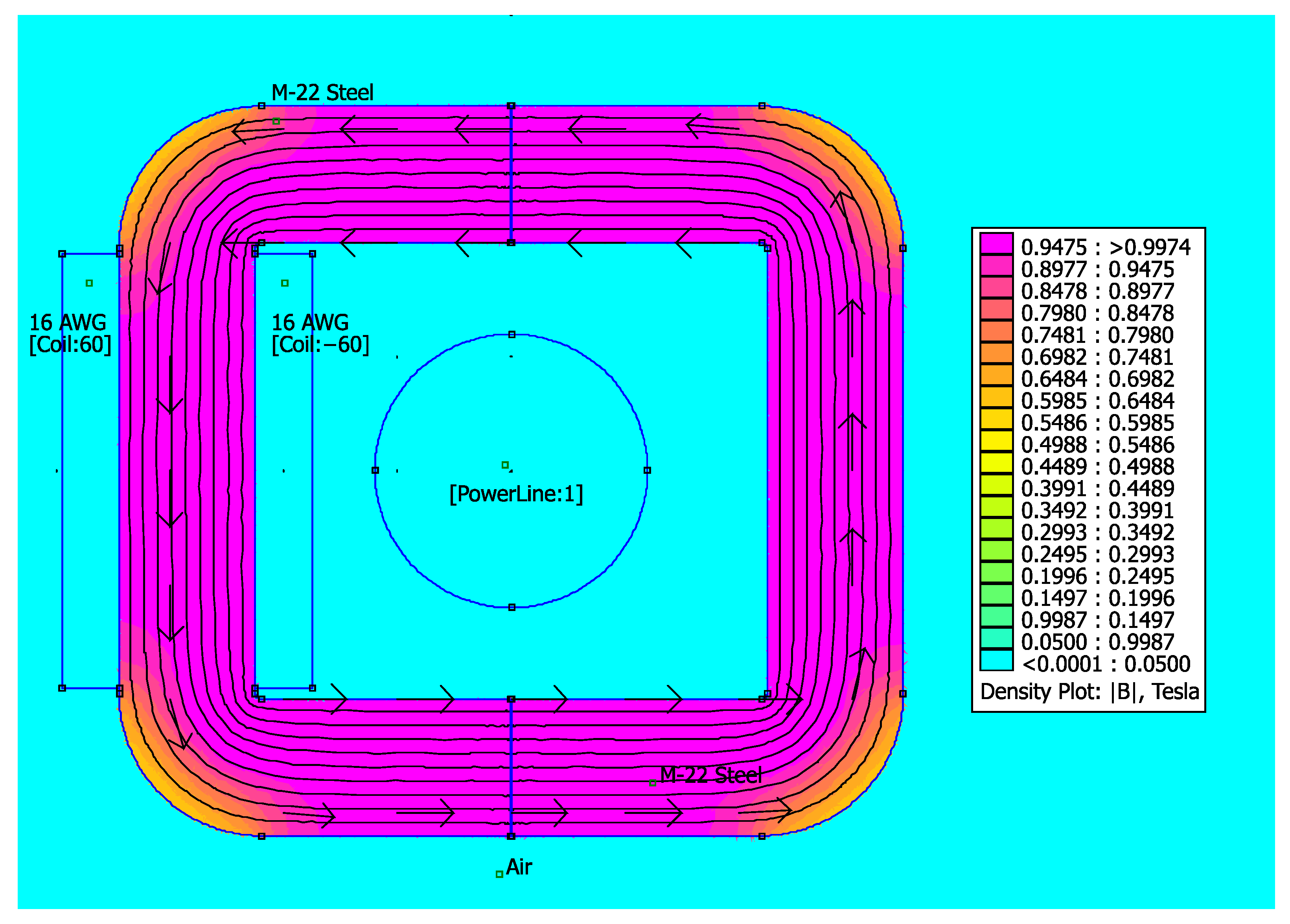
2.1. Energy Harvester

The charging station harvests energy from the alternating magnetic field around the overhead power line. This magnetic field is generated by the current flowing through the conductor. The harvester converts the present magnetic energy into electromotive force to power electronic devices or batteries. In order to achieve a reasonable tradeoff between weight and energy harvested, the energy harvesting charging station was designed to deliver up to 150 watts. The harvester (Figure 2) consists of:
  • A ferromagnetic core, which provides a path that concentrates the magnetic flux;
  • The primary winding, which is actually the power line, powered by an AC source;
  • A coil wound on the core (the secondary winding), which induces the current and receives energy from the primary winding to deliver it to the load.
In addition, an auxiliary battery can be connected to decouple the harvested energy from the charging process, which stores energy to ensure a fast charging process.
Figure 2. Energy harvester with split core, coil and power line.
Applsci 13 10175 g002
The materials used in the ferromagnetic core should have high permeability to the 50/60 Hz magnetic field to provide a high level of magnetic induction. They should also have low hysteresis loss to prevent overheating and minimize energy loss. Owing to its high performance, permeability, price and manufacturing flexibility, a grain-oriented silicon steel material was selected for the ferromagnetic core. The core is formed into thin sheets, which are coated to provide high resistance between them to minimize losses due to eddy currents. The core shape was defined to improve magnetic coupling while minimizing overall weight and utilizing the window area for winding placement (patent pending EP 3 605 793 A1).
The power cable constitutes the primary winding, which is formed by a single turn, typically using a large-diameter cable. The core is designed with a sufficiently large window area to accommodate a variety of commercial power cables. Conversely, the secondary coil uses an enameled copper wire. The cable diameter was selected to carry the secondary short-circuit current, considering the possibility of its temperature increasing due to the power line overheating. The amount of energy harvested is not affected by the number of turns in the secondary coil; hence, the number of turns was selected to match the induced voltage and the drone’s battery voltage over the current range of the power line. A split core was selected to ease the installation of the harvester on the power line. U-shaped cores were determined to optimize inductive coupling while minimizing the window area.
A core model derived from Maxwell’s equations was used for the mathematical representation of the harvester. The primary side current in the overhead power line is denoted as I p ( t ) and assuming sinusoidal AC and a secondary side current ( I s ( t ) ) in a coil with N s turns, the magnetomotive force measured in ampere-turns as seen by the core is expressed as:
A T c o r e t = I p sin w t N s I s ( t )
Then the magnetic field strength ( H r , t ) at a radial distance of r away from the center of the overhead power line is expressed as:
H r , t = A T c o r e t 2 π r = I p sin w t N s I s ( t ) 2 π r
The magnetic flux density ( B r , t ) is determined by the BH curve of the silicon steel core. An Arctan function was used to model the BH curve, where B s a t denotes the saturation threshold of the ferromagnetic material, and α is a curve-fitting parameter.
B r , t = B s a t 2 π arctan H r , t α = B s a t 2 π a r c t a n I p sin w t N s I s ( t ) 2 π r α
Simplifying the core shape in the induction equation for a toroidal core and denoting the inner and outer radius and length of the toroidal core as r i , r o and l , respectively, the induced voltage V t is expressed as:
V t = r i r o N s l B r , t t r = N s l B s a t 2 π 2 α · w I p cos w t N s I s t t · l n r o 2 + I p sin w t N s I s ( t ) 2 4 π 2 α 2 r i 2 + I p sin w t N s I s ( t ) 2 4 π 2 α 2
where I s t is assumed to be sinusoidal and dependent on the value of the load impedance.
A window area was defined in the core to place the coils and the grooved pads. The window utilization factor was maximized to bring the ferromagnetic core as close as possible to the power line. Finite element simulation was conducted to determine the magnetic field within the ferromagnetic core. The core creates a magnetic path with low reluctance, directing the existing magnetic field around the power line generated by the current flowing through the conductor. The magnetic field is subsequently confined within the core, creating an electromotive force in the secondary coil. When a charge is connected, the current induced in the secondary coil opposes the magnetic field in the primary coil, resulting in a reduction in the magnetic field through the core, as shown in Figure 3.
In contrast, without a load, the secondary coil generates a high peak voltage, and the ferromagnetic core may be saturated by the primary magnetic field. The overvoltage stage mitigates the mechanical stress on the core and prevents overvoltage of the electronics by short-circuiting the secondary coil. As a result, no voltage is induced, and the magnetic field through the ferromagnetic core is minimized.

2.2. Power Electronics

The designed drone charging station is with three power stages for the energy conversion and management process includes (Figure 4):
  • An electromagnetic induction energy harvester;
  • A rectifier and overvoltage protection;
  • A DC/DC converter with an MPPT charge controller.
The magnetic energy converted into electromotive force by the energy harvester has a sinusoidal AC component with a typical frequency of 50/60 Hz. The amplitude varies with the magnetic field and the load impedance. A rectifier circuit converts the AC voltage to DC, and the overvoltage protection prevents damage to the power electronics due to overvoltage. Two low-side MOSFETs short-circuit the harvester coil when the battery is unable to drain the collected energy, and TVS diodes prevent voltage transients.
Figure 4. Power stage diagram for energy conversion and management.
Applsci 13 10175 g004
A buck–boost DC/DC converter provides a compact solution for multicell and multichemistry drone battery charging applications. The buck–boost charger operates over a wide input and output voltage range and offers high efficiency. An MPPT charge controller is used to maximize the amount of current flowing from the energy harvester to the battery. The maximum power varies mainly with the current on the overhead line; then, the MPPT algorithm in the charge controller is used to extract the maximum available power from the energy harvester under certain conditions.

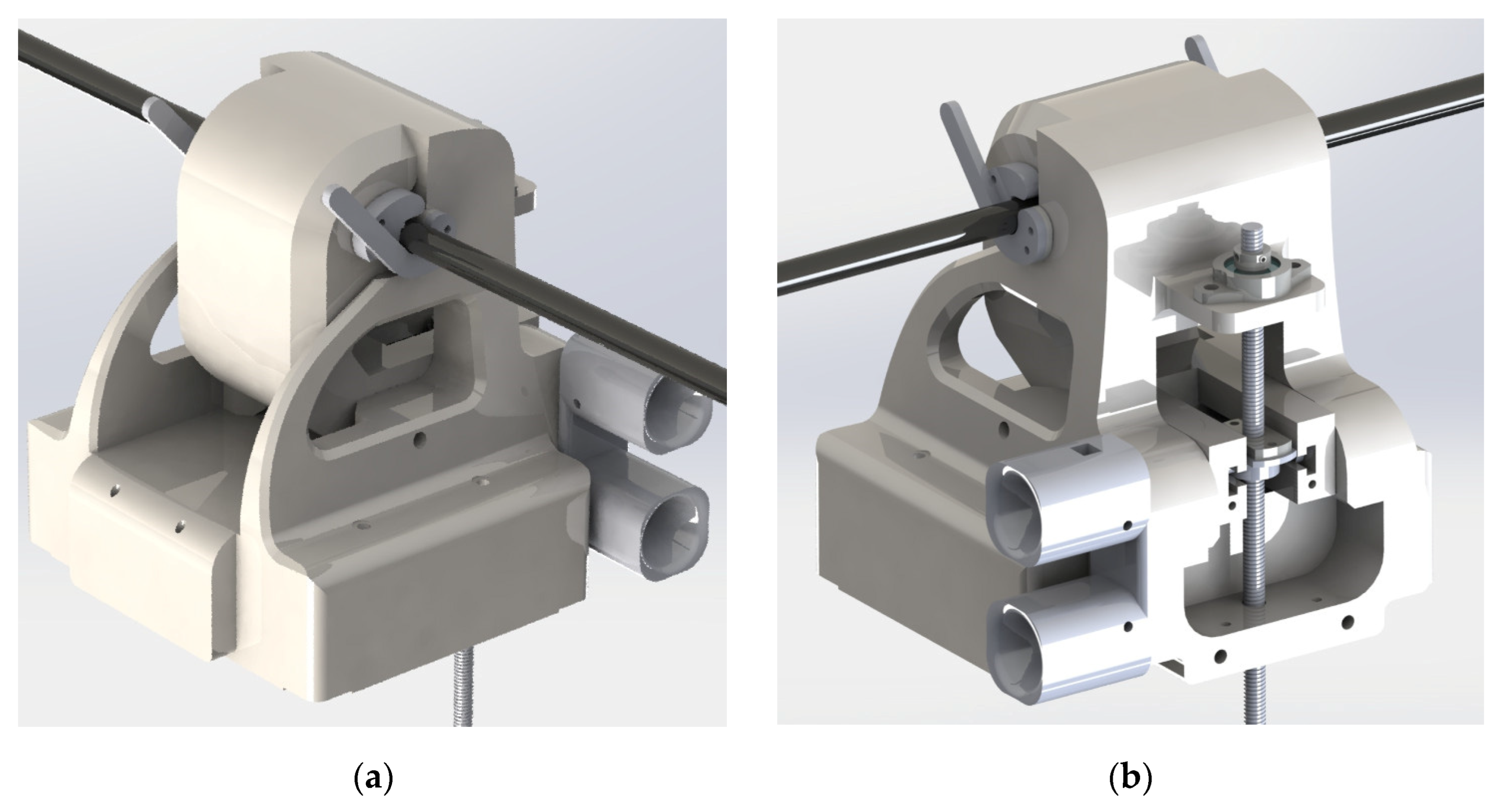
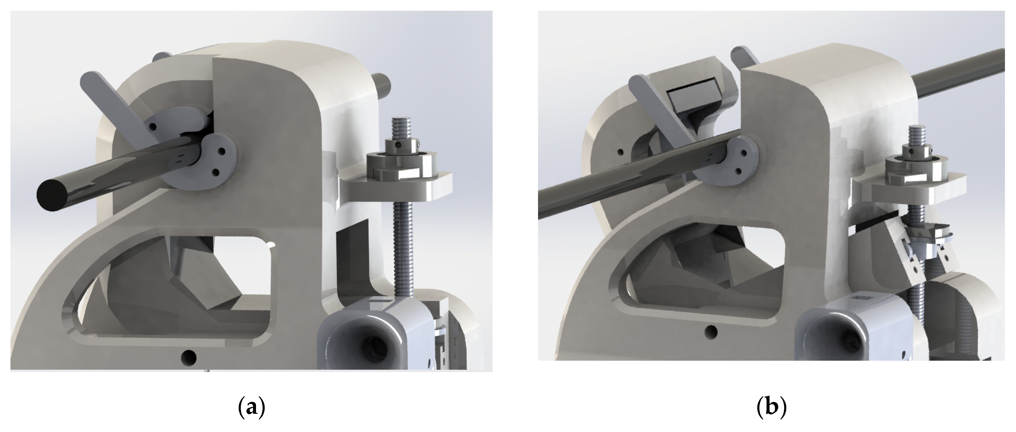
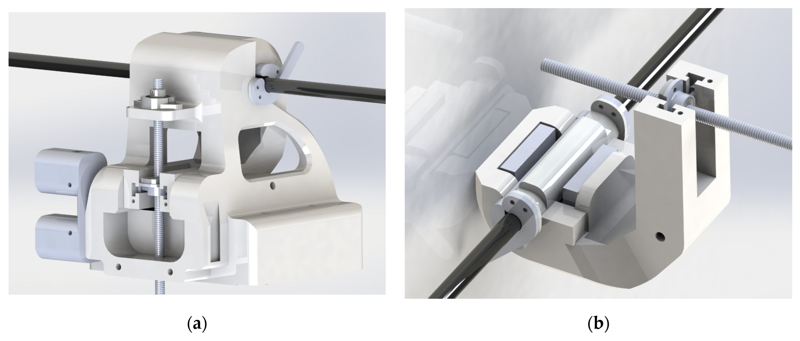
2.3. Mechanical Clamp Design

A clamping mechanism is proposed to ensure alignment and a minimum gap between the ferromagnetic cores. Figure 5a shows the two parts of the clamp holding the cable, while Figure 5b shows the clamp-closing mechanism located at the rear. This mechanical design maximizes the flux concentration in an effective and low-reluctance magnetic path, improving the energy-harvesting capability. In order to meet the requirements of drone integration, effector manipulation and weather hazards, the mechanical design was optimized to provide:
  • Easy vertical docking of the charging station and the power cable;
  • Low weight ≈ 5 kg;
  • Strong clamping for harsh environments;
  • Easy installation and robotic manipulation.
Figure 5. Drone charging station for overhead power lines designed in the Aerial-Core project: (a) front view; (b) back view.
Applsci 13 10175 g005
During the installation process, the UAV brings the open clamp close to the cable. Figure 6a illustrates how the shape of the claw guides the cable for accurate positioning. As shown in Figure 6b, the ferromagnetic core achieves a low-reluctance magnetic path to harvest energy from the magnetic field around the cable when the clamp is closed. A set of interchangeable jaw pads ensures an efficient grip between the cable and the clamp, while allowing the charger to be used on cables with different diameters. These grooved pads are designed to increase roughness and therefore friction, preventing the charger from rotating on the cable.
A two-part clamp design was defined to perform the opening and closing movements of the clamp during the installation and removal maneuvers (Figure 7a). While the lower half of the clamp remains fixed, the upper half can rotate around a fixed axis (Figure 7b). A worm gear mechanism produces the rotation to move the clamp (Figure 8a). This mechanism is designed to be operated by a single actuator. The servo rotary motion is converted into linear motion via a screw-and-nut system mounted on the motor shaft. Each rotation of the threaded rod produces a rotation in this threaded coupling, which, since the axial movement of the rod is limited, results in movement along the axis of the clamp guide (Figure 8b). The movement along the guide allows the clamp to open and close.

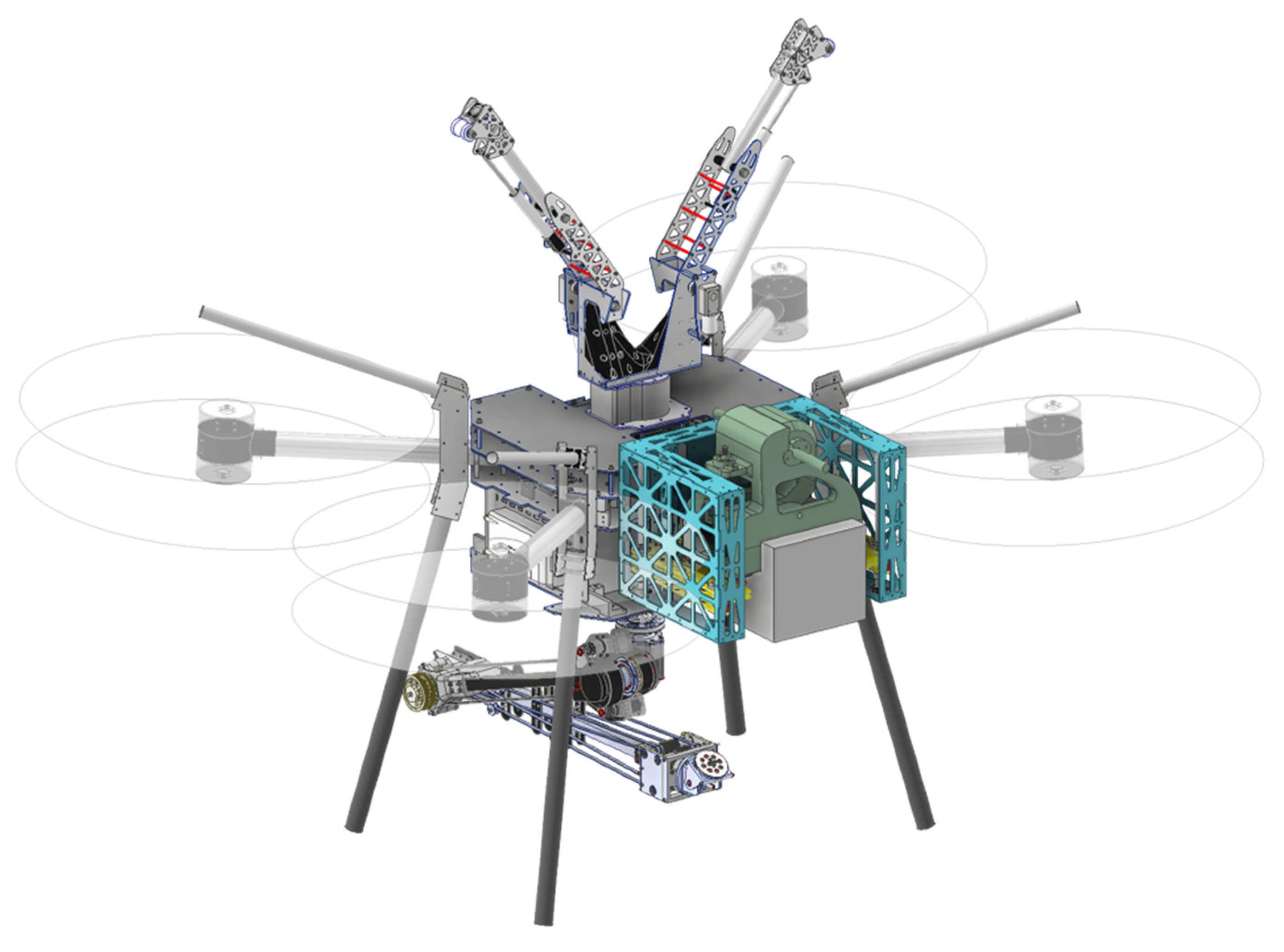
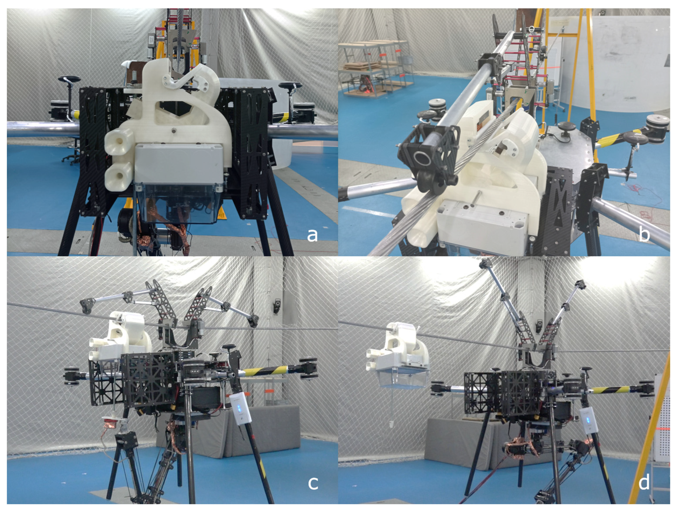
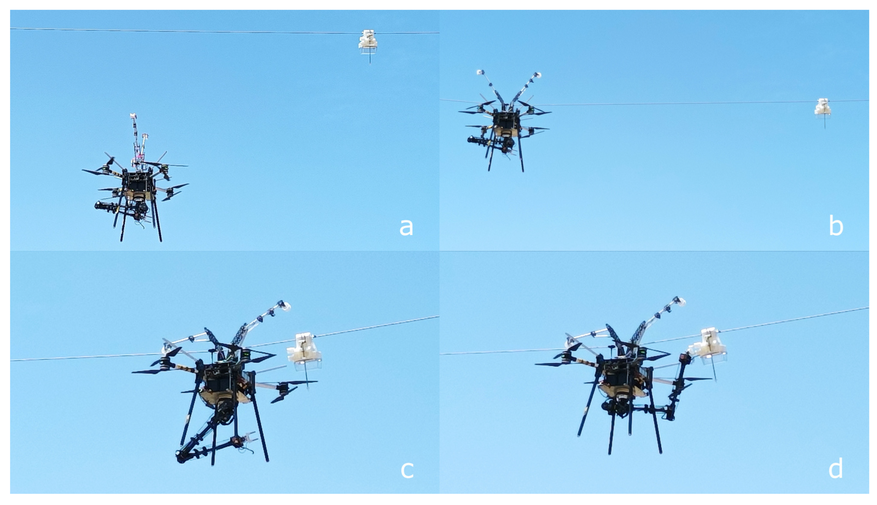
3. Unmanned Aerial Vehicle Manipulation

The Main Local Manipulation Platform (MLMP) (Figure 9) is a general-purpose power line inspection and maintenance UAV developed under the Aerial-Core project. The MLMP combines several technologies, such as a system to perch on a power line, cable detection algorithms, a robotic arm and end effectors to install accessories on overhead lines. The MLMP was used to install and test the charging station described in this paper. This section describes the MLMP modules involved in manipulating the charging station.

3.1. Perching Module

The proposed module consists of an active perching mechanism with a specially designed hook to safely perch on overhead power lines. Once the drone is positioned under the cable, either by manual or autonomous commands, the perching module is responsible for controlling the system during the ascent phase and for attaching the drone to the cable. This is achieved through a combination of the perching mechanism and dedicated perception and control software. The perching mechanism provides the drone with a reliable means of hooking in and out of the cable and allows the propeller motors to be shut down while the drone is perched. This module also gives the UAV the ability to move along the axis of the cable for precise installation of power line accessories.
The metallic fixing hook is designed to receive the electric arc during the approach process. The drone’s electronics are shielded and connected to the same potential as the chassis to reduce interference. After perching, the drone becomes equipotential to the line. However, during installation, it is important to consider the electric company’s safety parameters in terms of meeting the correct spacing between phases to prevent any interference caused by the drone.

3.2. Manipulation Module
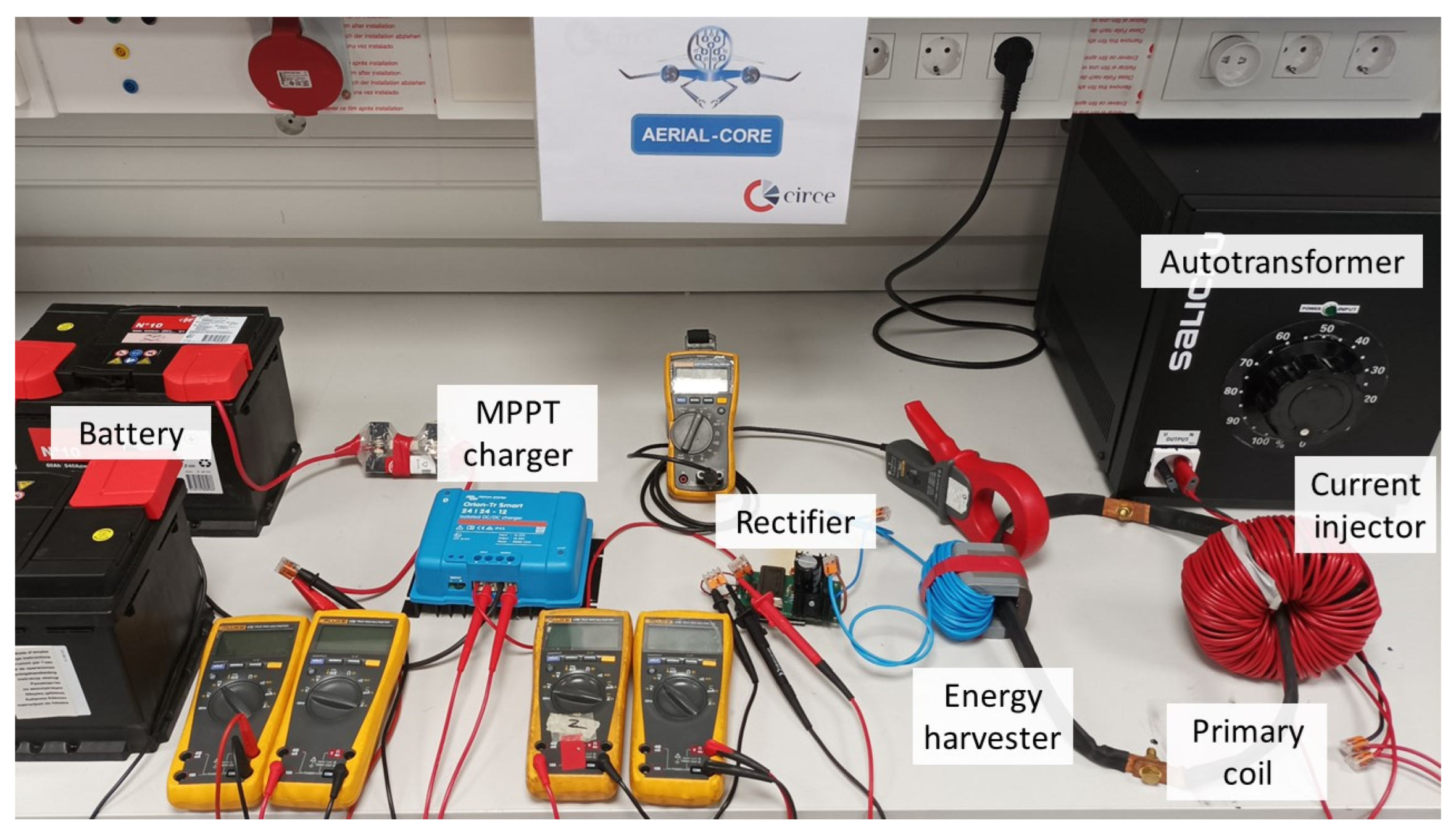
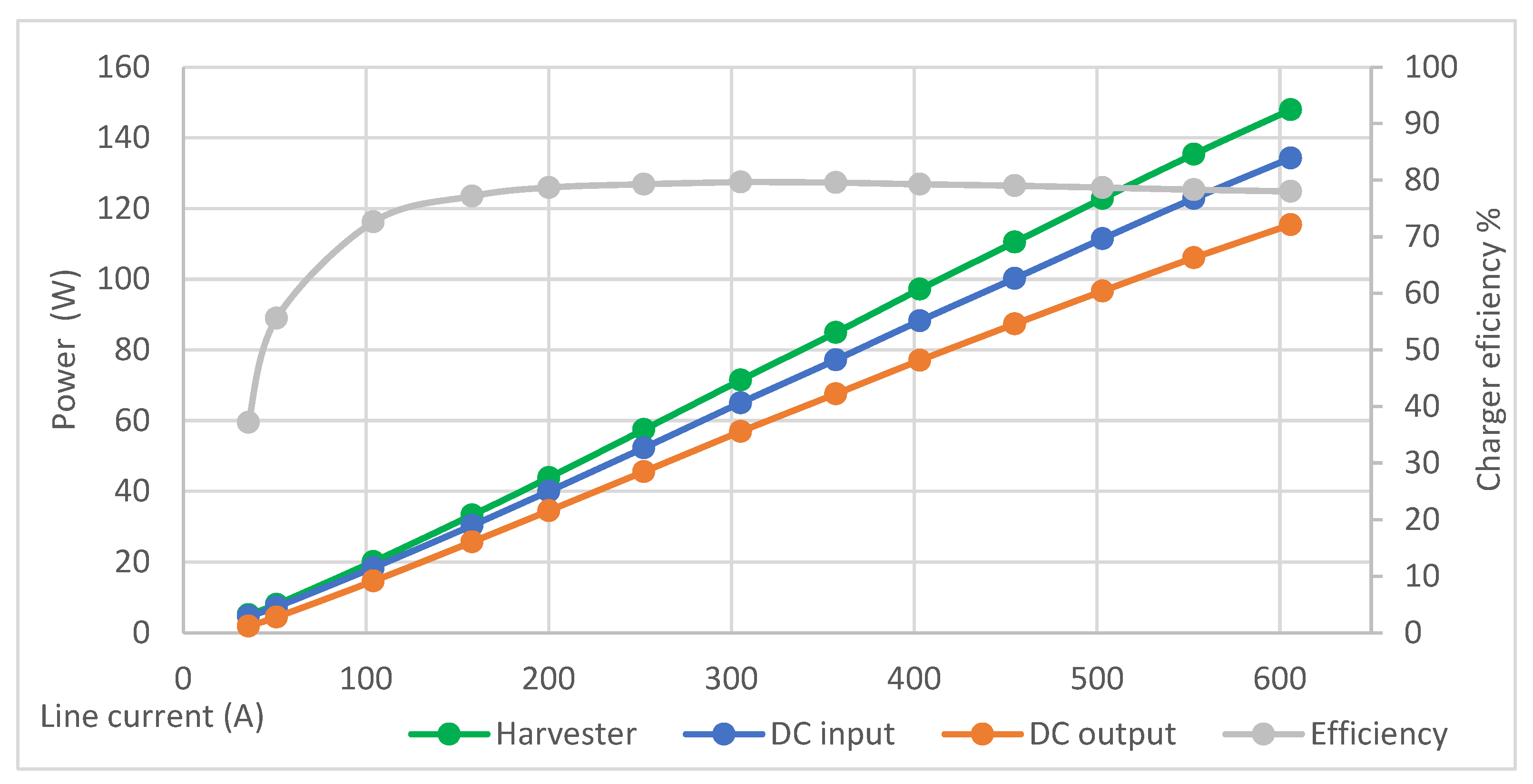
The manipulation module provides the system with the equipment and functionalities to manipulate overhead power line accessories. Due to the morphological and operational differences between accessories, a robotic arm integrated with the drone, in combination with dedicated end effectors, is proposed to achieve a versatile module. The developed arm is an anthropomorphic robotic arm with six degrees of freedom (DoF). In order to perform complex manipulation operations, the robotic arm has a geared spherical wrist. The weight of the arm is approximately 3 kg, with a payload of 3.5 kg.
Some constraints are considered for the manipulation of the charging station. To reduce disturbances to the drone’s flight control system, the influence on the UAV’s center of gravity must be considered. In addition, the weight exceeds the payload of the robotic arm. To overcome these challenges, a novel approach to the transport and assembly of the charging station is proposed. A support platform (Figure 9) fixes the charging station to the front of the UAV during flight, close to its center of gravity, taking advantage of the UAV’s payload and the large front area designed to carry additional tools.
This approach also reduces the stress on the robotic arm during flight, minimizing the risk of malfunction. The charging station platform is located below the perching mechanism to prevent interference during the perching maneuver. For this reason, the platform has a lift to position the charging station on the cable during installation. The lift raises the charging station by inserting the clamp into the cable and holding it in position. Finally, the robot arm actuates the worm gear with an ad hoc end effector to close the clamp and secure the charging station to the cable.

4. Results

A prototype charging station and an MLMP were manufactured and tested in several environments. First, a laboratory test for energy harvesting characterization is addressed. Then, experimental robotic manipulation and real power line testing are described.

4.1. Energy Harvesting

Experimental verification was conducted for energy-harvesting technology for aerial drone applications along an overhead power line. The charging station’s characteristics were analyzed using the test bench depicted in Figure 10. Testing revealed that the alignment of the core and the gap between the two halves have a significant impact on harvesting capacity. The test bench replicates an ideal scenario with optimal alignment and force to close the core with minimal impact from any resulting gaps. Table 3 defines the energy harvester designed for the charging station and its electronic power specifications.
The test bench (Figure 10) is fitted with an autotransformer to control the current induced into the primary coil by the current injector. The charging station harvests energy from the magnetic field, and a rectifier converts induced AC to DC. An isolated DC/DC charger with MPPT control delivers the energy to the battery. A wide range of 50 Hz line current points was generated to assess the amount of energy that can be harvested by the drone charging station, as well as the efficiency of the power electronics (Table 4, Figure 10).
The DC/DC converter starts working from 35 A on the power line, providing current to charge the battery. The harvested AC power is rectified, then adjusted to the battery voltage. The MPPT controller adjusts the load impedance to deliver the maximum available power from the energy harvester to the battery under certain conditions. The charging test was conducted during the bulk phase, when the current in the charger is not limited by the battery capacity.
Thus, the battery starts charging at 35 A on the AC line. Figure 11 shows a linear dependence between the line current and the energy harvested, which increases linearly from 5 W harvested at 35.6 A to a maximum of 148 W harvested at 606 A on the line. Furthermore, due to non-linearities in the power electronics, the efficiency is lower at lower power levels. However, it can be considered as constant and equal to 80% in the range of 150–600 A AC line current.
Efficiency is determined by the rectifier and the DC/DC converter. The passive diode-based rectifier generates a voltage drop, and the DC/DC buck/boost efficiency varies with input and output current and voltage. The overall electronic efficiency is close to 80%. These power losses, of which 42% are attributable to the rectifier stage and almost are attributable 58% to the DC/DC converter, result in efficiencies of 91% and 86%, respectively for these stages.
Thus, an average 500 Wh battery would be charged from 20% to 80% in just 2 h using the maximum power point of 148 W at 600 A. This charging time may be acceptable for certain maintenance operations or fully autonomous tasks of the UAV. However, there are other tasks that require coordination with operators or other elements for which this charging time may not be feasible. To minimize or even eliminate these charging times, inductive charging could be combined with battery swapping, or a small stationary battery could be incorporated into the charging station. This stationary battery could store energy while the drone is in flight and quickly transfer this energy to the UAV when needed.

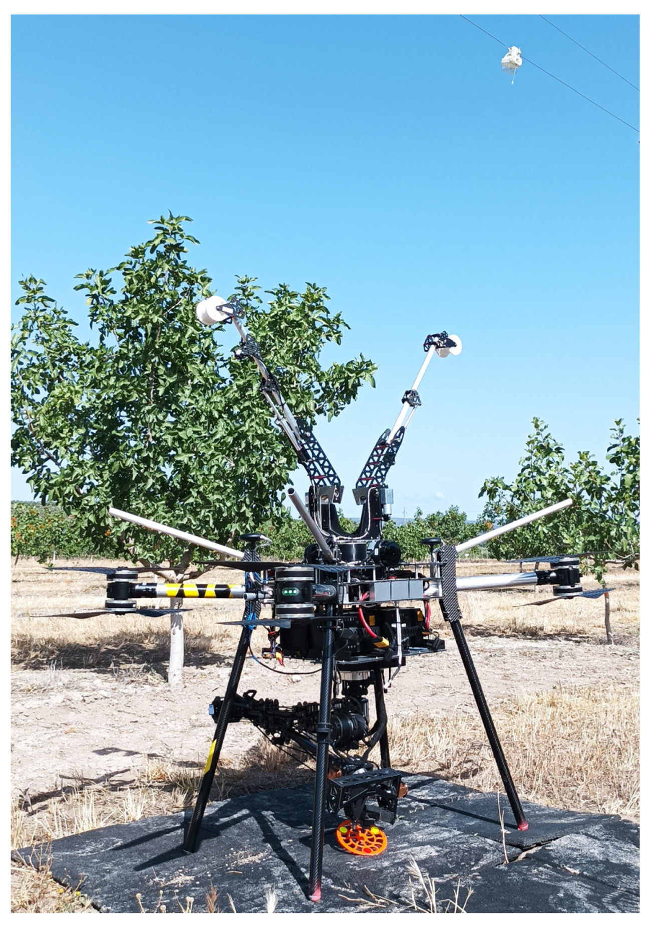
4.2. Experimental Robotic Manipulation

Robotic manipulation experiments were conducted to demonstrate the application of the charging station under various scenarios. The testing process was divided into three phases: laboratory experiments, controlled outdoor mockup and real power line.
The first set of experiments was conducted in an indoor mockup equipped with a five-meter section of power line suspended three meters above the ground by a metal structure. The experiments shown in Figure 12 consisted of installing the charging station using the robotic arm, the elevation platform and the end effector. First, the charging station was attached to the MLMP; then, the MLMP was manually placed on the line (Figure 12a). The installation of the charging station was carried out in a teleoperated mode, manually controlling the movements of the elevation platform (Figure 12b) and the arm (Figure 12c). Finally, the undocking maneuver was performed (Figure 12d).
In addition, a second experiment was performed to test the mechanical coupling between the drone and the charging station when the station is installed and the drone is charging its batteries.
The second set of experiments was conducted in a similar but larger mockup at an outdoor facility at the ATLAS Tactical Centre in Spain. The same experiments were carried out as in the laboratory mockup but, this time, fully autonomously. The results demonstrated the installation of the station and the coupling between the MLMP and the charging station. More details about the results of the outdoor mockup can be found in Supplementary Materials Video.
Finally, the third set of experiments was carried out on a real power line (Figure 13). The aim was to perform a charging maneuver by coupling the MLMP to the station already installed on the cable (Figure 13a). The MLMP performed the maneuver of approaching the power line. The vehicle then perched on the line (Figure 13b) and moved along the cable to approach the charging station (Figure 13c). Finally, the UAV performed the coupling of the MLMP to the charging station (Figure 13d).
These tests validated the mechanical design of the charging station, MLMP and end-effector integration in a real operational environment.

5. Discussion

This paper presents a novel charging station for drones that exploits power line magnetic fields. We propose the use of an inductive harvester to charge the drone’s battery. This approach is based on an easy-to-install charging station that can be deployed by a multirotor drone on an overhead AC power line without modifying the electrical infrastructure. A lightweight drone charging station capable of harvesting 145 W of power at a 600 A line current is reported. This research provides evidence that harvesting technology is suitable for powering multirotor drones with perching capabilities. The results suggest that aerial robotic manipulators can provide a cutting-edge technology to ensure the safety and quality of the electrical grid, minimize hazardous work and reduce maintenance costs.
These results are part of the Aerial-Core project and establish a first approach for research projects focused on aerial robotic manipulation on overhead power lines. Further research is required to maximize energy density, improve energy harvesting and conversion efficiency for drone charging stations and simplify the design of drone and robotic effectors. The development of wireless coupling between charging stations and drones can help to universalize this technology for multiple purposes. A long-term demonstrator in a real environment is also required to provide further information for research.

Supplementary Materials

The following supporting information can be downloaded at: https://www.mdpi.com/article/10.3390/app131810175/s1, Integration experiments videos are available on Aerial-Core project web page at https://aerial-core.eu (accessed on 1 September 2023) and on official social media channels.

Author Contributions

Investigation, A.-M.M.-G. and J.-M.M.-P.; Writing—original draft, A.-M.M.-G.; Writing—review & editing, J.-M.M.-P., J.B.-F. and J.-F.S.-O. All authors have read and agreed to the published version of the manuscript.

Funding

This research was funded by the European Commission (grant number H2020-ICT-2018-20).

Institutional Review Board Statement

Not applicable.

Informed Consent Statement

Not applicable.

Data Availability Statement

Not applicable.

Acknowledgments

The authors gratefully acknowledge the support of Enel Group and the contribution of Jacob Rodriguez-Rivero, Carlos Gaitan-Poyatos and Luis Monereo Perez-Carasa of the Aerial-Core project. We also gratefully acknowledge Aníbal Ollero from the University of Seville for the coordination of the Aerial-Core project, Michele Marolla and Pasquale Campanile from the University of Naples Federico II and Goran Vasiljevic from the University of Zagreb for their contributions on the manipulation platform, as well as ATLAS Flight Centre for support during the validation tests shown in figure below (Integration experiments with drone and charging station at the Atlas Centre (Jaen) performed in 2023 for the Aerial-Core H2020 project). Finally, the authors appreciate the valuable contributions of Alberto Serrano-Royo and Alberto Pérez-Luño from the Circe Foundation for the 3D design, printing and manufacturing of charging station prototypes and Rafael Cuevas Molero from CATEC for the 3D design of the elevation platform.

Conflicts of Interest

The authors declare no conflict of interest. The funders had no role in the design of the study; in the collection, analyses or interpretation of data; in the writing of the manuscript; or in the decision to publish the results.

References

  1. Elbanhawi, M.; Mohamed, A.; Clothier, R.; Palmer, J.L.; Simic, M.; Watkins, S. Enabling technologies for autonomous MAV operations. Prog. Aerosp. Sci. 2017, 91, 27–52. [Google Scholar] [CrossRef]
  2. Hasan, A.; Kramar, V.; Hermansen, J.; Schultz, U.P. Development of Resilient Drones for Harsh Arctic Environment: Challenges, Opportunities, and Enabling Technologies. In Proceedings of the 2022 International Conference on Unmanned Aircraft Systems (ICUAS), Dubrovnik, Croatia, 21–24 June 2022; pp. 1227–1236. [Google Scholar]
  3. Bolognini, M.; Izzo, G.; Marchisotti, D.; Fagiano, L.; Limongelli, M.P.; Zappa, E. Vision-based modal analysis of built environment structures with multiple drones. Autom. Constr. 2022, 143, 104550. [Google Scholar] [CrossRef]
  4. Obayashi, S.; Kanekiyo, Y.; Uno, H.; Shijo, T.; Sugaki, K.; Kusada, H.; Nakakoji, H.; Hanamaki, Y.; Yokotsu, K. 400-W UAV/Drone inductive charging system prototyped for overhead power transmission line patrol. In Proceedings of the 2021 IEEE Wireless Power Transfer Conference (WPTC), San Diego, CA, USA, 1–4 June 2021; pp. 2021–2023. [Google Scholar]
  5. Xu, C.; Li, Q.; Zhou, Q.; Zhang, S.; Yu, D.; Ma, Y. Power Line-Guided Automatic Electric Transmission Line Inspection System. IEEE Trans. Instrum. Meas. 2022, 71, 1–18. [Google Scholar] [CrossRef]
  6. Skriver, M.; Stengaard, A.; Schultz, U.P.; Ebeid, E. Experimental Investigation of EMC Weaknesses in UAVs During Overhead Power Line Inspection. In Proceedings of the 2022 International Conference on Unmanned Aircraft Systems (ICUAS), Dubrovnik, Croatia, 21–24 June 2022; pp. 626–635. [Google Scholar]
  7. Dietsche, A.; Cioffi, G.; Hidalgo-Carrio, J.; Scaramuzza, D. Powerline Tracking with Event Cameras. In Proceedings of the 2021 IEEE/RSJ International Conference on Intelligent Robots and Systems (IROS), Prague, Czech Republic, 27 September–1 October 2021; pp. 6990–6997. [Google Scholar]
  8. Kyriakakis, N.A.; Stamadianos, T.; Marinaki, M.; Marinakis, Y. The electric vehicle routing problem with drones: An energy minimization approach for aerial deliveries. Clean. Logist. Supply Chain 2022, 4, 100041. [Google Scholar] [CrossRef]
  9. Cosson, M.; David, B.; Arzel, L.; Poizot, P.; Rhallabi, A. Modelling of photovoltaic production and electrochemical storage in an autonomous solar drone. eScience 2022, 2, 235–241. [Google Scholar] [CrossRef]
  10. Gómez-Lagos, J.; Rojas-Espinoza, B.; Candia-Véjar, A. On a Pickup to Delivery Drone Routing Problem: Models and algorithms. Comput. Ind. Eng. 2022, 172, 108632. [Google Scholar] [CrossRef]
  11. Conte, C.; Rufino, G.; de Alteriis, G.; Bottino, V.; Accardo, D. A data-driven learning method for online prediction of drone battery discharge. Aerosp. Sci. Technol. 2022, 130, 107921. [Google Scholar] [CrossRef]
  12. Stewart, W.; Guarino, L.; Piskarev, Y.; Floreano, D. Passive Perching with Energy Storage for Winged Aerial Robots. Adv. Intell. Syst. 2021, 5, 2100150. [Google Scholar] [CrossRef]
  13. Bereg, S.; Díaz-Báñez, J.M.; Haghpanah, M.; Horn, P.; Lopez, M.A.; Marín, N.; Ramírez-Vigueras, A.; Rodríguez, F.; Solé-Pi, O.; Stevens, A.; et al. Optimal placement of base stations in border surveillance using limited capacity drones. Theor. Comput. Sci. 2022, 928, 183–196. [Google Scholar] [CrossRef]
  14. Momeni, M.; Soleimani, H.; Shahparvari, S.; Afshar-Nadjafi, B. Coordinated routing system for fire detection by patrolling trucks with drones. Int. J. Disaster Risk Reduct. 2022, 73, 102859. [Google Scholar] [CrossRef]
  15. ElSayed, M.; Foda, A.; Mohamed, M. Autonomous drone charging station planning through solar energy harnessing for zero-emission operations. Sustain. Cities Soc. 2022, 86, 104122. [Google Scholar] [CrossRef]
  16. Pinto, R.; Lagorio, A. Point-to-point drone-based delivery network design with intermediate charging stations. Transp. Res. Part C Emerg. Technol. 2022, 135, 103506. [Google Scholar] [CrossRef]
  17. Ahmadian, N.; Lim, G.J.; Torabbeigi, M.; Kim, S.J. Smart border patrol using drones and wireless charging system under budget limitation. Comput. Ind. Eng. 2022, 164, 107891. [Google Scholar] [CrossRef]
  18. Famili, A.; Stavrou, A. Eternal Flying: Optimal Placement of Wireless Chargers for Nonstop Drone Flights. In Proceedings of the 2022 International Conference on Electrical, Computer and Energy Technologies (ICECET), Prague, Czech Republic, 20–22 July 2022; pp. 1–6. [Google Scholar]
  19. Huang, H.; Savkin, A.V. Deployment of Charging Stations for Drone Delivery Assisted by Public Transportation Vehicles. IEEE Trans. Intell. Transp. Syst. 2022, 23, 15043–15054. [Google Scholar] [CrossRef]
  20. Shin, M.; Kim, J.; Levorato, M. Auction-Based Charging Scheduling with Deep Learning Framework for Multi-Drone Networks. IEEE Trans. Veh. Technol. 2019, 68, 4235–4248. [Google Scholar] [CrossRef]
  21. Huang, H.; Savkin, A.V. A Method of Optimized Deployment of Charging Stations for Drone Delivery. IEEE Trans. Transp. Electrif. 2020, 6, 510–518. [Google Scholar] [CrossRef]
  22. Arafat, M.Y.; Moh, S. JRCS: Joint Routing and Charging Strategy for Logistics Drones. IEEE Internet Things J. 2022, 9, 21751–21764. [Google Scholar] [CrossRef]
  23. Chittoor, P.K.; Chokkalingam, B.; Mihet-Popa, L. A Review on UAV Wireless Charging: Fundamentals, Applications, Charging Techniques and Standards. IEEE Access 2021, 9, 69235–69266. [Google Scholar]
  24. Lu, M.; Bagheri, M.; James, A.P.; Phung, T. Wireless Charging Techniques for UAVs: A Review, Reconceptualization, and Extension. IEEE Access 2018, 6, 29865–29884. [Google Scholar] [CrossRef]
  25. Mohsan, S.A.H.; Othman, N.Q.H.; Khan, M.A.; Amjad, H.; Żywiołek, J. A Comprehensive Review of Micro UAV Charging Techniques. Micromachines 2022, 13, 977. [Google Scholar] [CrossRef] [PubMed]
  26. Mohamed, A.; Taylor, G.K.; Watkins, S.; Windsor, S.P. Opportunistic soaring by birds suggests new opportunities for atmospheric energy harvesting by flying robots. J. R. Soc. Interface 2022, 19, 20220671. [Google Scholar] [CrossRef]
  27. Kirubakaran, B.; Hosek, J. Extending UAV’s Operational Time through Laser Beam Charging: System Model Analysis. In Proceedings of the 2022 45th International Conference on Telecommunications and Signal Processing (TSP), Prague, Czech Republic, 13–15 July 2022; pp. 322–328. [Google Scholar]
  28. Lee, D.; Zhou, J.; Lin, W.T. Autonomous battery swapping system for quadcopter. In Proceedings of the 2015 International Conference on Unmanned Aircraft Systems (ICUAS), Denver, CO, USA, 9–12 June 2015; pp. 118–124. [Google Scholar]
  29. Mostafa, T.M.; Muharam, A.; Hattori, R. Wireless battery charging system for drones via capacitive power transfer. In Proceedings of the 2017 IEEE PELS Workshop on Emerging Technologies: Wireless Power Transfer (WoW), Chongqing, China, 20–22 May 2017; pp. 1–6. [Google Scholar]
  30. Lan, L.; Polonelli, T.; Qin, Y.; Pucci, N.; Kwan, C.H.; Arteaga, J.M.; Boyle, D.; Yates, D.C.; Yeatman, E.M.; Mitcheson, P.D. An induction-based localisation technique for wirelessly charged drones. In Proceedings of the 2020 IEEE PELS Workshop on Emerging Technologies: Wireless Power Transfer (WoW), Seoul, Republic of Korea; pp. 275–277.
  31. Chittoor, P.K.; Bharatiraja, C. Solar Integrated Wireless Drone Charging System for Smart City Applications. In Proceedings of the 2021 IEEE 6th International Conference on Computing, Communication and Automation (ICCCA), Arad, Romania, 17–19 December 2021; pp. 407–412. [Google Scholar]
  32. Obayashi, S.; Kanekiyo, Y.; Shijo, T. UAV/Drone Fast Wireless Charging FRP Frustum Port for 85-kHz 50-V 10-A Inductive Power Transfer. In Proceedings of the 2020 IEEE Wireless Power Transfer Conference (WPTC), Seoul, Republic of Korea, 15–19 November 2020; pp. 219–222. [Google Scholar]
  33. Tian, X.; Chau, K.T.; Liu, W.; Lee, C.H.T. Analysis of Multi-Coil Omnidirectional Energy Harvester. IEEE Trans Magn. 2021, 57, 1–6. [Google Scholar] [CrossRef]
  34. Matsukura, M.; Moro, R.; Keicho, N.; Shimamura, K.; Yokota, S. Wireless Charging for Hovering-Drone via Millimeter Wave. In Proceedings of the 2022 Wireless Power Week (WPW), Bordeaux, France, 5–8 July 2022; pp. 772–775. [Google Scholar]
  35. Park, B.; Huh, S.; Kim, J.; Kim, H.; Shin, Y.; Woo, S.; Park, J.; Brito, A.; Kim, D.; Par, H.H.; et al. The Magnetic Energy Harvester with Improved Power Density Using Saturable Magnetizing Inductance Model for Maintenance Applications near High Voltage Power Line. IEEE Access 2021, 9, 82661–82674. [Google Scholar] [CrossRef]
  36. Paul, S.; Chang, J. Design of novel electromagnetic energy harvester to power a deicing robot and monitoring sensors for transmission lines. Energy Convers. Manag. 2019, 197, 111868. [Google Scholar] [CrossRef]
  37. Park, B.; Huh, S.; Kim, H.; Shin, Y.; Woo, S.; Ahn, S. Design and Analysis of Magnetic Energy Harvester with Improved Power Density for Drone Charging Station Near High Voltage Power Line. In Proceedings of the 2022 International Conference on Electronics, Information, and Communication (ICEIC), Jeju, Republic of Korea, 6–9 February 2022; pp. 2–3. [Google Scholar]
  38. Iversen, N.; Schofield, O.B.; Cousin, L.; Ayoub, N.; Vom Bogel, G.; Ebeid, E. Design, Integration and Implementation of an Intelligent and Self-recharging Drone System for Autonomous Power line Inspection. In Proceedings of the 2021 IEEE/RSJ International Conference on Intelligent Robots and Systems (IROS), Prague, Czech Republic, 27 September–1 October 2021; pp. 4168–4175. [Google Scholar]
  39. Stuhne, D.; Hoang, V.D.; Vasiljevic, G.; Bogdan, S.; Kovacic, Z.; Ollero, A.; Ebeid, E.S.M. Design of a Wireless Drone Recharging Station and a Special Robot End Effector for Installation on a Power Line. IEEE Access 2022, 10, 88719–88737. [Google Scholar] [CrossRef]
  40. Bogel GVom Cousin, L.; Iversen, N.; Ebeid, E.S.M.; Hennig, A. Drones for Inspection of Overhead Power Lines with Recharge Function. In Proceedings of the 2020 23rd Euromicro Conference on Digital System Design (DSD), Kranj, Slovenia, 26–28 August 2020; pp. 497–502. [Google Scholar]
  41. Stewart, W.; Floreano, D.; Ebeid, E. A Lightweight Device for Energy Harvesting from Power Lines with a Fixed-Wing UAV. In Proceedings of the 2022 International Conference on Unmanned Aircraft Systems (ICUAS), Dubrovnik, Croatia, 21–24 June 2022; pp. 86–93. [Google Scholar]
  42. Iversen, N.; Kramberger, A.; Schofield, O.B.; Ebeid, E. Novel Power Line Grasping Mechanism with Integrated Energy Harvester for UAV applications. In Proceedings of the 2021 IEEE International Symposium on Safety, Security, and Rescue Robotics (SSRR), New York, NY, USA, 25–27 October 2021; pp. 34–39. [Google Scholar]
  43. Aerial-Core H2020-ICT-2018-20. Aerial-Core Website. Available online: https://aerial-core.eu/ (accessed on 1 September 2023).
Figure 1. Main local manipulation platform and charging station placed on the overhead power line (top-right corner) during integration experiments at the ATLAS Centre (Jaen) for the Aerial-Core project.
Applsci 13 10175 g001
Figure 3. Magnetic field simulation with energy harvesting for battery charging via a 200 A power line.
Applsci 13 10175 g003
Figure 6. Ferromagnetic core located inside the clamp to achieve a low-reluctance magnetic path to harvest energy from the magnetic field around the cable and interchangeable jaw pads: (a) clamp opened; (b) clamp closed.
Applsci 13 10175 g006
Figure 7. Two-piece clamp with a hinged half that can pivot around a fixed axis to execute the opening and closing movements: (a) clamp closed; (b) clamp opened.
Applsci 13 10175 g007
Figure 8. Worm-driven mechanism to operate the clamp: (a) view of the screw-and-nut system; (b) detailed view of the clamp guide.
Applsci 13 10175 g008
Figure 9. MLMP and support platform with charging station.
Applsci 13 10175 g009
Figure 10. Laboratory energy-harvesting test bench.
Applsci 13 10175 g010
Figure 11. Energy harvested in different power stages and total power conversion efficiency (based on Table 4).
Applsci 13 10175 g011
Figure 12. Indoor experiments installing the charging station using the elevation platform and the robotic arm with end effector: (a) MLMP perched on the line; (b) elevation platform positions the charging station on the cable; (c) robotic arm actuates the worm gear with an ad hoc end effector to close the clamp; (d) undocking of the MLMP and the charging station.
Applsci 13 10175 g012
Figure 13. Real power line experiments: (a) MLMP flight to overhead power line; (b) MLMP perched on the line; (c) MLMP moving along the cable; (d) coupling of the MLMP with the charging station.
Applsci 13 10175 g013
Table 1. Limit values considered for overhead power lines.
Overhead Power LineValueUnit
Power line voltage 1<400kV
Frequency50/60 2Hz
Power line diameter9–24mm
Current<600A
1 The safety clearance must be observed when working on live overhead lines. 2 Non-European power systems with 60 Hz are also considered.
Table 2. Professional unmanned aerial vehicle reference specifications.
AircraftValueUnit
Weight≈15kg
Payload<10kg
Flight time (payload-dependent)10–50min
Battery capacity250–1000Wh
Table 3. Charging station energy harvester specifications.
Power LineValueUnit
Current0–600A
Frequency50Hz
CoreValueUnit
Weight1089g
MaterialGrain-oriented silicon steel
Width40mm
Height45mm
Length60mm
Thickness12mm
CoilValueUnit
Turns60
MaterialCopper
MPPT ConverterValueUnit
Input voltage16–35V
Output voltage20–30V
Nominal current12A
Battery PackValueUnit
Voltage24V
Capacity40Ah
ChemicalsPb–acid
Table 4. Voltage (V), current (I) and power (P) in power electronic stages at several line currents.
Line current (A)35.651104158200252305357403455503553606
Harvester secondary windingV15.4515.9117.3617.7317.9318.218.4318.6518.8619.0819.2619.4819.65
I0.3320.5051.1611.8782.4483.1583.8774.5545.1535.7926.3786.957.53
P5.18.020.233.343.957.571.584.997.2110.5122.8135.4148.0
DC inputV14.1114.5215.8816.1716.3616.5716.7816.9617.1317.3117.4817.6817.83
I0.3320.5051.1611.8782.4483.1583.8774.5545.1535.7926.3786.957.53
P4.77.318.430.440.052.365.177.288.3100.3111.5122.9134.3
DC outputV24.1524.1624.224.2524.324.3524.4324.4924.5424.6224.6724.7624.81
I0.0790.1850.6051.061.4221.8722.332.763.1413.5483.9194.2844.654
P1.94.514.625.734.645.656.967.677.187.496.7106.1115.5
Efficiency37.255.672.677.278.779.379.779.679.379.078.778.378.0
Disclaimer/Publisher’s Note: The statements, opinions and data contained in all publications are solely those of the individual author(s) and contributor(s) and not of MDPI and/or the editor(s). MDPI and/or the editor(s) disclaim responsibility for any injury to people or property resulting from any ideas, methods, instructions or products referred to in the content.

