Abstract
This study introduces innovative designs for frequency-reconfigurable antennas that utilize ring resonators combined with either PIN diodes or RF switches. These designs enhance the versatility, adaptability, and overall performance of the antennas in wireless communication systems. By controlling the switches and ring resonator, the antenna’s resonant frequencies and bandwidths can be adjusted, allowing for compatibility with various communication standards and frequency ranges. The proposed antenna exhibits four distinct operational states, each characterized by different resonance frequencies and operating frequency bands. Return loss, radiation pattern, radiation efficiency, and surface current distribution are analyzed for each state. State-1 (ON-ON) and State-2 (OFF-ON), which are characterized by resonance frequencies of 2.4 GHz and 3.33 GHz respectively, offer ranges suitable for Wi-Fi, Bluetooth, ISM, and IoT applications. State-3 (ON-OFF), with a resonance frequency of 3.0 GHz and bandwidth spanning from 2.59 GHz to 3.643 GHz, complies with Wi-Fi, Wi-Fi 6, and IoT requirements. State-4 (OFF-OFF) covers the band centered around 3.45 GHz. It is compatible with many applications such as 5G mid-band, Wi-Fi 6E, IoT, and cellular systems. The proposed antenna designs are versatile and compact since the overall antenna dimensions are 25 × 18 × 1.6 mm3. The radiation efficiency of the antenna configuration varies depending on operational states. By utilizing the advantages of both ring resonators and RF switches, the proposed antenna configurations offer new solutions that enhance their performance in wireless communication systems. This study compares the effects of using PIN diodes and SPDT switches on the performance of antennas and also examines the DC biasing effect on antenna characteristics. The simulation results are validated by the experimental analysis. The proposed antenna designs offer a new approach for wireless communication systems by using both ring resonators and RF switches.
Keywords:
antenna; frequency; IoT; ISM; PIN diode; radiation pattern; reconfigurability; SPDT switch; Wi-Fi; Wi-Fi 6/6E; 5G 1. Introduction
The rapid growth in wireless communication systems and the need for improved communication performance have led researchers and engineers to seek novel multipurpose antenna structures [,,,,,,]. As new technologies such as 5G, Wi-Fi 6/6E, and the Internet of Things (IoT) continue to emerge, the demand for compact devices with efficient radiating elements has become critical. Reconfigurable antennas offer the advantage of serving as multiple single-purpose antennas, with their low cost, reduced weight, and compact size. These antennas can control their operational frequency, bandwidth, radiation pattern, and polarization according to the system requirements [,]. However, designing a reconfigurable antenna and integrating it efficiently into a system is still a challenge for antenna designers and researchers. Converting a conventional antenna to a reconfigurable structure requires changing its internal structure using various techniques [,]. Several critical parameters must be carefully considered, such as gain, efficiency, radiation pattern, and impedance matching for all states. Reconfigurable antennas can be classified according to their functional characteristics, such as operating frequency, radiation pattern, and polarization [].
Frequency-reconfigurable antennas play a crucial role in sub-6 GHz and wireless applications due to their ability to adapt to different frequency bands and communication standards. These antennas provide precise frequency control, which allows them to adjust their resonant frequencies accordingly []. This ability is important in wireless communication systems that require antennas to operate at different frequency bands. The importance of frequency-reconfigurable antennas in sub-6 GHz and wireless applications is highlighted by several research studies. For example, Irfan et al. [] presented a cactus-shaped frequency-reconfigurable antenna for sub-10 GHz wireless applications. The antenna utilizes PIN diodes as electrical switches to achieve reconfigurability, enabling operation in four different frequency ranges []. This demonstrates the potential for frequency-reconfigurable antennas to adapt to various wireless applications. In the context of 5G technology, frequency-reconfigurable antennas have gained significant attention. Ahmad et al. [] reports the design of a multiband compound reconfigurable 5G antenna for sub-6 GHz wireless applications. The antenna can operate in multiple frequency bands, including ISM, WLAN, Wi-Fi, and Airport Surveillance Radar (ASR) bands []. Furthermore, the use of frequency-reconfigurable antennas can improve the working flexibility and space utilization of terminal equipment []. By utilizing a single antenna module that can cover multiple sub-6 GHz working bands, the need for multiple antennas can be eliminated, leading to more efficient and compact wireless devices []. The potential for frequency-reconfigurable antennas to address the spectrum crunch at microwave frequencies is also worth noting. The underutilized millimeter wave (mm Wave) frequencies, typically ranging from 30 to 300 GHz, can be explored for cellular applications []. However, mm Wave frequencies face challenges such as severe path loss and absorption/scattering by gases. Frequency-reconfigurable antennas offer a solution by allowing for the efficient utilization of available frequency bands, including sub-6 GHz bands []. Iqbal et al. makes significant contributions to 5G sub-6 GHz applications and wireless communications []. They propose a novel antenna design that achieves dual-band operation and dual-circular polarization. The antenna’s ability to operate in multiple frequency bands allows for compatibility with different 5G frequency bands, ensuring wide coverage and flexibility in wireless communication systems []. The antenna design utilizes a single-fed configuration, which simplifies the feeding network and reduces the complexity of the antenna system. Furthermore, the study demonstrates the use of a dielectric resonator antenna (DRA) in the proposed design. DRAs have been widely recognized for their compact size, high radiation efficiency, and low profile, making them suitable for 5G sub-6 GHz applications. The study provides insights into the DRA design and performance optimization techniques for achieving dual-band and dual-circular polarization [,]. The study in [] presents a rectangular dielectric resonator antenna (RDRA) designed for a circularly polarized (CP) response in the 5G New Radio (NR) sub-6 GHz band applications. The innovation lies in a uniquely shaped conformal metal feeding strip that effectively excites the RDRA in a higher-order mode, leading to optimized high gain utilization. Xu et al. discuss the manipulation of polarization states of electromagnetic waves using tunable metasurfaces []. The authors combine theory and experiment to demonstrate the capabilities of a tunable metasurface incorporating diodes as active elements to dynamically control the reflection phase of EM waves and manipulate the helicity of incident circular-polarized EM waves. The paper provides a detailed explanation of the experimental setup, results, and analysis, making it a valuable contribution to the field of optics and electromagnetic wave manipulation []. He-Xiu et al. discuss the use of the kirigami technique to create metamaterials that can control electromagnetic waves in a reconfigurable manner []. The authors introduce a kirigami-inspired sparse meta-architecture for adaptive invisibility based on independent operations of frequency, bandwidth, and amplitude. They demonstrate reconfigurable invisibility management with abundant EM functions and a wide tuning range using three enantiomers (A, B, and C) of different geometries characterized by the folding angle. The paper provides a new avenue for multifunctional smart devices []. Slawomir et al. propose a novel formulation for the design of high-performance scattering metasurfaces through optimization-based explicit RCS reduction []. The authors discuss the recent advances in the development of coding metasurfaces and the potential benefits they offer in realizing radar cross-section (RCS) reduction.
In the context of the antenna design, the ring resonator that supports resonant modes at specific frequencies has emerged as a valuable component in antenna design [,,,,]. The ring resonator offers a range of possibilities for enhancing antenna performance and enabling frequency reconfigurability. This resonator introduces additional resonance frequencies that can modify the antenna’s frequency response and radiation characteristics. By changing the parameters of the ring resonator, such as its dimensions, materials, or coupling method, the resonant frequencies can be controlled, providing frequency reconfigurability to the antenna. By utilizing the resonant behavior of the ring resonator, certain frequencies can be allowed and others blocked, allowing the antenna to operate in specific frequency bands. This capability facilitates frequency switching or filtering, enabling the antenna to adapt to different communication standards or frequency allocations. Furthermore, the ring resonator can be designed as a tunable element in the antenna structure. By incorporating tunable materials or active components such as varactors or MEMS devices into the ring resonator, the resonant frequency can be adjusted, allowing for frequency reconfiguration [,]. The design of frequency-reconfigurable antennas with ring resonators can be accomplished by utilizing PIN diodes or Single-Pole-Double Throw (SPDT) switches. Jain et al. focus on the design and application of metamaterial absorbers for various purposes, including sensing applications []. The research contributes to the field of metamaterial-based antenna design by proposing novel designs of multi-band and tunable absorbers that can be used for sensing applications, such as liquid refractive index sensing [] and protein concentration measurement []. These absorbers exhibit high sensitivity and can operate in the terahertz frequency range. Additionally, the study explores the use of different resonator structures, such as Jerusalem crosses [], T-shaped gaps [], and ring-strip resonators [], to achieve the desired absorption characteristics. The research also investigates the impact of substrate etching on the sensitivity of metamaterial absorbers []. Overall, the study provides valuable insights and design guidelines for the development of metamaterial-based antennas with enhanced sensing capabilities. The study in [] explores the use of metamaterials (MMs) in antenna design and highlights their potential contributions and implications. It also discusses various applications of metamaterials in antennas, such as achieving high efficiency in amorphous silicon solar cells [], overcoming the diffraction limit in super lenses [], and designing hepta-band and multi-band metamaterial absorbers for sensing applications [,]. Furthermore, the study presents several examples of metamaterial absorbers with specific characteristics, such as polarization insensitivity [,], wide-angle absorption [], high Q-factors [], and multiple absorption bands [,]. These examples demonstrate the potential of metamaterials in designing antennas with desired properties and functionalities. Taking everything into account, the switching element is of utmost importance in the design of frequency-reconfigurable antennas. It enables the antenna to adapt to different frequencies, improves spectrum efficiency, enhances system flexibility, and allows for compact and integrated designs []. The selection of the appropriate switching element is crucial for achieving optimal antenna performance and meeting the requirements of the target wireless communication systems. PIN diodes are commonly used for frequency reconfigurability in antennas due to their fast switching speed and low power consumption [,]. One approach is to place the PIN diodes in proximity to the ring resonators. By controlling the biasing states of the PIN diodes, the electromagnetic coupling between the ring resonator and the antenna can be adjusted, thereby changing the antenna’s resonant frequency. The PIN diodes can be connected in series or parallel with the ring resonators, allowing for different configurations and switching behaviors. By selectively biasing the PIN diodes, the coupling between the ring resonators and the antenna can be modified, resulting in different resonant frequencies and frequency reconfigurability. In addition to this, RF switches provide fast switching capabilities and are compatible with high-frequency applications []. In this approach, RF switches are used to control the coupling between the ring resonators and the antenna. By activating or deactivating specific RF switches, the electromagnetic coupling can be modified, resulting in frequency reconfiguration. The RF switches can be connected in series or parallel with the ring resonators to achieve the desired switching behavior. By controlling the state of the RF switches, the coupling strength between the ring resonators and the antenna can be adjusted, enabling the antenna to operate at different frequencies. In both cases, the ring resonators act as frequency-selective components, allowing for frequency reconfigurability in the antenna design. The specific configuration and placement of the ring resonators, PIN diodes, and RF switches depend on the desired performance objectives, the antenna structure, and the targeted frequency bands. Hence, it is worth noting that the choice between PIN diodes and RF switches depends on various factors such as switching speed requirements, power consumption limitations, reliability considerations, and integration compatibility with the antenna design. Designers need to carefully evaluate these factors to select the most suitable combination of ring resonators and switching elements for achieving frequency reconfigurability in antenna designs.
This paper presents a novel contribution to the literature in the field of antenna design and wireless communication. By integrating ring resonators as frequency-controlling elements, the proposed antenna design introduces a novel approach that enhances adaptability and overall performance of the reconfigurable antenna. Unlike conventional designs that often focus on individual components, the proposed antenna utilizes the unique properties of ring resonators to achieve reconfigurability, enabling precise frequency control. The incorporation of RF switches further amplifies the adaptability of the antenna, allowing for dynamic switching between resonance frequencies and bandwidths, thereby making it versatile in wireless communication applications. This study addresses a significant gap in the existing literature by performing a comparative analysis of two switching methods, PIN diodes and SPDT switches, for frequency-reconfigurable antennas in the sub-6 GHz range. Moreover, the antenna’s ability to exhibit similar operating bands in different states enhances the reliability of the system. This characteristic is of paramount importance in wireless communication systems, ensuring stable connectivity even in the presence of interference or signal degradation. The omni-directional radiation pattern characteristic of the proposed antenna further emphasizes the significance of the design. By combining these features into an antenna design, this paper introduces an innovative approach to current research and paves the way for advancements in wireless communication technology. The capabilities of the proposed design such as improved frequency adaptability, reliability, and broad coverage, make a significant contribution to the existing literature for advancements in antenna engineering and its practical applications.
2. Materials and Methods
2.1. Ring Resonator
Marcatili’s paper in 1969 introduces the simulation of integrated ring resonators for bandpass filters. Figure 1 illustrates the layout of the channel dropping filter proposed by Marcatili, which has since become the standard configuration for such filters []. This configuration consists of two straight waveguides, also known as bus or port waveguides, coupled to the ring resonator through either directional coupler utilizing the evanescent field or multimode interference (MMI) couplers. Figure 2 depicts the basic configuration of a ring resonator channel dropping filter, as described by Yariv [,]. In this configuration, there is unidirectional coupling between a ring resonator with a radius r and a waveguide. The interaction between the waveguide and the ring resonator can be described using a matrix relation as given in Equation (1):
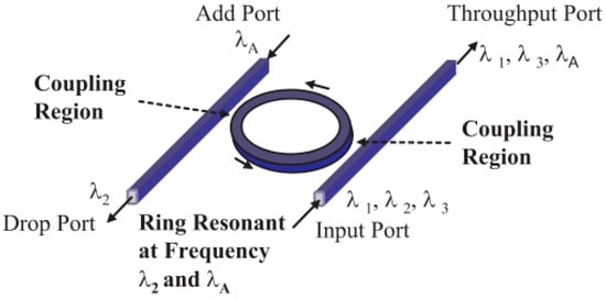
Figure 1.
Basic ring resonator structure in drop channel filtering [].
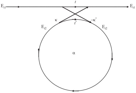
Figure 2.
General schematic of ring resonator coupling [].
The complex mode amplitudes E in the system are normalized, meaning that their squared magnitudes represent the modal power. The values of the coupler parameters t and κ are specific to the coupling mechanism employed. The asterisk (*) signifies the conjugated complex value of t and κ.
The matrix exhibits symmetry because the considered networks adhere to the principle of reciprocity. As a result, the matrix elements are symmetric based on Equation (2):
To simplify the model further, the value of Ei1 is set to 1. This choice simplifies the analysis by fixing the initial mode amplitude at the input port of the ring resonator. With this assumption, the round trip in the ring can be expressed by Equation (3), which describes the behavior of the signals propagating through the ring:
Here, α is the loss coefficient of the ring, and it represents the amount of signal attenuation or power loss within the ring. The variable α is 1 when there is no loss. The variable θ is defined as the product of the angular frequency ω, the circumference of the ring L, and the reciprocal of the phase velocity c. Specifically, θ = ωL/c. The phase velocity of the ring mode, denoted as c, is related to the speed of light in a vacuum, denoted as c0, and the effective refractive index neff. More precisely, c = c0/neff. By incorporating the effective refractive index, neff, into the coupling relations of the ring, the characteristics of the ring resonator can be described more accurately. To relate the vacuum wavenumber k to the wavelength λ, the following relationship is employed: k = 2π/λ. The vacuum wavenumber represents the spatial frequency of the electromagnetic wave. By incorporating these definitions and relationships, the effective refractive index, neff, can be introduced into the coupling relations of the ring resonator, allowing for a more comprehensive description of the ring’s behavior as shown in Equation (4):
Various types of ring resonators are proposed in the literature to meet the requirements for different application areas []. An add-drop ring resonator, which is another configuration of the ring resonator, is made up of a single input, single output waveguide, and one ring resonator structure as represented in Figure 3.
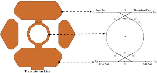
Figure 3.
Add-drop ring resonator: a single input, single output waveguide with ring resonator structure.
The add-drop ring resonator plays an important role in antenna design due to its ability to provide frequency reconfigurability, a highly desirable feature in wireless communication systems. Antennas designed with add-drop ring resonators can adjust their operating frequency range according to restrictions specified by regulations. Hence, the antenna can adapt to different frequency bands by reconfiguring the resonance properties of the ring resonator. Antenna performance parameters such as bandwidth, gain, and radiation efficiency can be improved by using add-drop ring resonators. The add-drop ring resonator has the advantage of providing communication with different standards simultaneously without a significant increase in the antenna footprint.
2.2. Reconfigurable Antenna
The novel proposed frequency-reconfigurable microstrip antenna, illustrated in Figure 4a–d, features a compact size. The overall dimensions of the proposed antenna are 25 × 18 × 1.6 mm3. The ring resonator dimensions are detailed in Figure 4a. The ground plane length (Lg) represented in Figure 4b is varied from 3 to 6 mm in steps of 1 mm. After parametric study, the optimum value of Lg is taken as 4 mm as depicted in Figure 4b. The dimensions of the physical parameters (Ws: substrate width, Ls: substrate length, Wf: feed line width, Lf: feed line length, gap: g, Lg: ground plane length) are also depicted in Figure 4a,b. Figure 4c,d illustrate the utilization of switches, specifically the PIN diode of BAR64-02V and SPDT switches of CG2415M6 models, respectively. The proposed antenna incorporates a decagon ring resonator, which is inserted using these switching components. The antenna structure is fabricated on an FR-4 substrate material with a relative permittivity of 4.3, tangent loss of 0.0025, and a substrate thickness of 1.6 mm. The CST® Studio Suite 3D EM simulator (CST-MWS) is employed to analyze the antenna parameters. The overall schematic diagram of the proposed antenna structure is depicted to provide a comprehensive representation of the design.
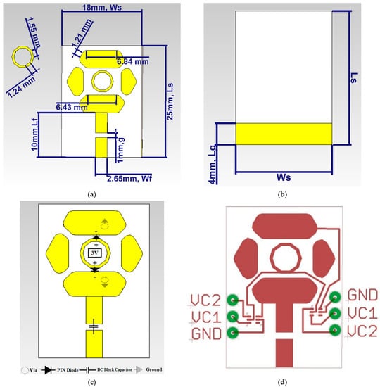
Figure 4.
(a) Top, (b) bottom, (c) PIN diode replacement, and (d) SPDT replacement of the proposed novel frequency reconfigurable antenna structure.
2.3. Design Procedure of the Proposed Antenna
A monopole antenna is a type of radio frequency (RF) antenna that consists of a single radiating element. It is widely used in various applications, including radio broadcasting, wireless communication, and more. The length of a monopole antenna is typically defined as one-quarter (1/4) of the wavelength of the radio signal it is designed to transmit or receive. This length is chosen to ensure efficient radiation and reception of electromagnetic waves. The formula to calculate the length (lm) of a monopole antenna is given by:
where:
- lm is the length of the monopole antenna (quarter wavelength) in meters.
- c is the speed of light in a vacuum, approximately 3 × 10⁸ m per second.
- f is the frequency of the radio signal in hertz (Hz).
It is clear from the above calculations that monopole antenna lengths for different frequencies (2.4 GHz, 3.5 GHz, and 3 GHz) are varied, and the length is decreased when the resonance frequency is increased. However, in this study, the use of a ring resonator aims to reduce the antenna dimensions. Ring resonators are common components in RF and microwave engineering that can be used to create compact and efficient antenna designs. They are often used to enhance certain properties of antennas or to achieve specific resonant frequencies. By incorporating a ring resonator into the antenna design, the physical length of the antenna is potentially reduced while maintaining or enhancing its performance characteristics.
2.4. Switching Mechanism
The proposed antenna structures are separately fabricated with two different switching elements, either the PIN diode of BAR6402-V or Single Pole Double Throw (SPDT) switches of CG2415M6 as detailed in Figure 5a,b, respectively. Based on the working principle of the switching components, a different measurement setup is utilized for each approach as shown in Figure 5c,d.
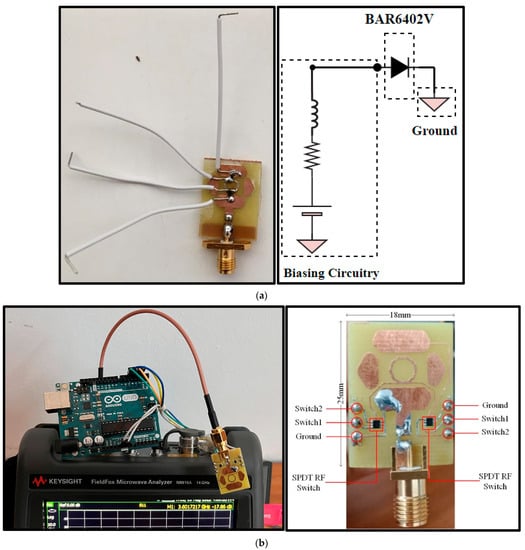
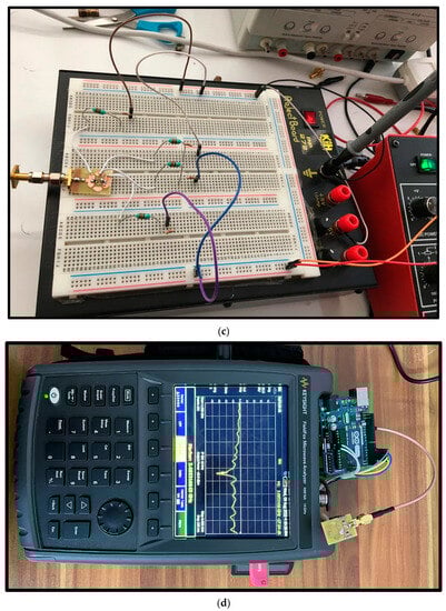
Figure 5.
The fabricated prototype antennas with (a) PIN diodes of BAR64-02V, and (b) RF switches of CG2415M6. Experimental setup for (c) PIN diodes and (d) SPDT switches.
Understanding the equivalent circuit behavior of the PIN diode and the block diagram of the SPDT switch is critical for designing efficient and reliable frequency-reconfigurable antenna systems. This knowledge enables precise control, optimization, and adaptability of the antenna’s performance, ensuring its successful integration and functionality in various communication applications. Figure 6 is detailed to allow designers to analyze and predict the performance of the component within the antenna system. Understanding the equivalent circuit behavior of the PIN diode BAR64-02V is important in the design and fabrication of frequency-reconfigurable antennas. This knowledge plays a crucial role in optimizing the antenna’s performance, analyzing its reconfigurability, predicting its behavior, and guiding the fabrication process. Figure 6a presents the equivalent circuit model of the BAR64-02V PIN diode. The model shows that when the PIN diode is forward-biased (positive voltage applied to the P-region and negative voltage applied to the N-region), it behaves as a series combination of a low-resistance resistor and an inductor, allowing current flow through it. This forward-biased state is known as the ON state of the PIN diode. Conversely, when the PIN diode is reverse-biased (positive voltage applied to the N-region and negative voltage applied to the P-region), it exhibits a parallel combination of a high-resistance resistor and capacitor in series with the inductor. This reverse-biased state is referred to as the OFF state of the PIN diode.
Figure 6.
(a) Equivalent circuit diagram of BAR64-02V; (b) block diagram, truth table, and evaluation circuit of CG2415M6 [].
Similarly, comprehending the block diagram and evaluation circuit of SPDT switches, such as the CG2415M6, is vital for designers to understand their functionality, control mechanisms, and performance characteristics. This knowledge aids in the design, integration, and fabrication of frequency-reconfigurable antennas. Figure 6b represents the truth table and block diagram of SPDT switches (CG2415M6 model). The SPDT switch consists of a single input or common terminal (COM) and two output terminals known as the normally open (NO) and normally closed (NC) terminals. In its resting or unactuated position, the COM terminal is connected to the NC terminal, and the NO terminal is disconnected. When the switch is actuated, the mechanical unit inside the switch changes the connection. In this new position, the COM terminal becomes connected to the NO terminal, and the connection between COM and NC is broken. The SPDT switch is commonly used to select between two different circuits or paths within a circuit. In this study, the COM terminal of the SPDT switch is connected to a digital input pin on the Arduino Uno, the NO terminal is connected to the Arduino’s 3-V power supply, and the NC terminal is connected to the ground (GND) on the Arduino. Depending on the switch state, the appropriate code is written in the Arduino program to perform specific actions, control other components, or make decisions based on the connections.
3. Results and Discussions
3.1. Simulation Results
Four different configurations of the proposed antenna are obtained based on the conditions of two switching components. Figure 7 illustrates the return loss (RL) characteristics of the proposed antenna. It is evident from Figure 7 that the resonance and operating frequencies are influenced by the states of switches. In State-1 (both switches are ON), the antenna exhibits a single band characteristic with a resonance frequency of 2.4 GHz. State-2 (D1 is OFF, D2 is ON) displays a single band characteristic with a resonance frequency of 3.33 GHz. State-3 (D1 is ON, D2 is OFF) results in a bandwidth ranging from 2.59 GHz to 3.643 GHz, with a resonance frequency of 3 GHz. Finally, State-4 (both switches are OFF) has an operating frequency band ranging from 2.95 GHz to 4.48 GHz. Analyzing the operating and resonance frequencies, the similarity in operating bands between State-1 and State-2, and State-3 and State-4 results in redundancy in frequency coverage. This redundancy ensures that even if one state experiences interference or signal degradation due to external factors, the antenna can quickly switch to the corresponding state with a similar band, maintaining uninterrupted communication and enhancing the overall system reliability. In dynamic wireless environments where the frequency spectrum availability changes over time, having similar operating bands in different states enables the antenna to adapt and optimize its performance based on the prevailing conditions. The antenna can intelligently switch between states to select the best operating band at any given moment, maximizing spectrum utilization and mitigating the effects of changing environmental factors. Depending on the communication requirements or application scenarios, the antenna can be deliberately configured to utilize one of the states that offer the most suitable band. For example, State-1 may be preferred for mid-band 5G communication, while State-3 could be chosen for Wi-Fi communication. This allows the antenna to be customized for specific communication standards or frequency allocations. Combining the bands covered by similar states can lead to bandwidth expansion. By utilizing both State-1 and State-2 or State-3 and State-4 simultaneously, the antenna can operate over a broader frequency range. This expanded bandwidth is advantageous for high data rate applications, such as video streaming or data-intensive tasks, as it increases the available data throughput. The ability to switch between states with similar bands can be utilized to avoid interference from neighboring wireless networks. By monitoring the surrounding environment and intelligently selecting the state with the least interference, the antenna can optimize its performance and maintain robust communication links. These findings demonstrate the capability of the proposed antenna configurations to adapt to different frequency bands and meet the requirements of specific communication systems. By utilizing this novel reconfigurable nature, the proposed antenna structure offers versatile performance and enables frequency tuning for optimal operation in various wireless communication applications. Table 1 illustrates the frequency bands obtained by the four states of the proposed antenna for various communication applications.
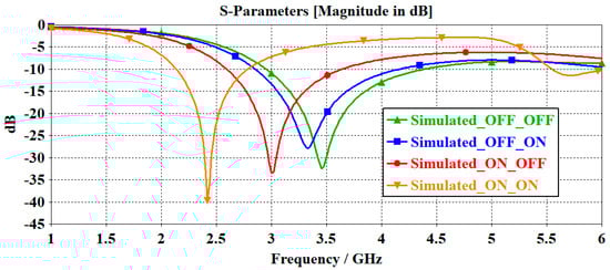
Figure 7.
The simulated reflection coefficient (S11) of the proposed frequency–reconfigurable antenna.

Table 1.
RF performance parameters of the frequency-reconfigurable antenna for each state.
The radiation pattern characteristics of the proposed antenna for each state at resonance frequencies are represented in Figure 8. As seen in Figure 8, radiation patterns show omni-directional behavior. For the applications such as Wi-Fi, Bluetooth, and IoT, the omni-directional radiation pattern is advantageous. Similarly, for 5G mid-bands, Wi-Fi 6E, and cellular bands, the omni-directional radiation pattern enables efficient communication with multiple devices in different directions.
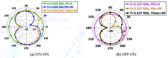
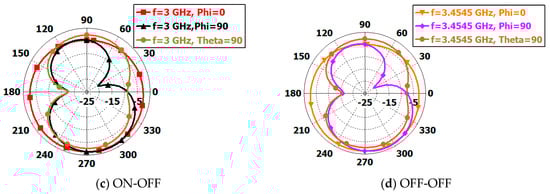
Figure 8.
The radiation pattern characteristics of (a) State-1 at 2.4 GHz, (b) State-2 at 3.27 GHz, (c) State-3 at 3 GHz, and (d) State-4 3.45 GHz of the proposed frequency reconfigurable antenna.
After analyzing the operating frequency and radiation pattern characteristic of the proposed antenna, the crucial frequencies, which are 3 GHz and 3.5 GHz, are observed for different states of the antenna as detailed in Figure 9. Hence, the comparison of these frequencies along with the different angles is examined to determine the beamforming capability of the proposed four different states. The main lobe directions are depicted in Table 2. It is also clear from Figure 9 and Table 2 that the ON-ON state is not provided since it does not radiate at the frequency of 3 GHz or 3.5 GHz. It is also deduced from these analyses that the proposed antenna structure with three states has a partial radiation pattern reconfigurability feature at 3.5 GHz where theta = 90°. Additionally, the radiation efficiency of the proposed antenna is shown in Figure 10 for each state to evaluate the effectiveness of the design.
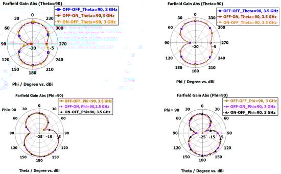
Figure 9.
Radiation pattern characteristic for each state with different angles where phi = 0°, phi = 90°, and theta = 90°.
Table 2.
The main lobe magnitude direction comparison for three states.
Figure 10.
Radiation efficiency of the proposed frequency-reconfigurable antenna for each switching state.
Another important performance parameter for the proposed antenna is depicted in Figure 10. It is clear from Figure 10 that different radiation efficiencies are observed. For the ON-ON state, the efficiency ranges from 0.3 to 0.48 as the frequency increases. In the ON-OFF state, the radiation efficiency ranges from 0.3 to 0.50 with increasing frequency. The OFF-OFF state has a radiation efficiency ranging from 0.32 to 0.58 as the frequency increases. Finally, the OFF-ON state has a radiation efficiency ranging from 0.35 to 0.5. These results are relevant for sub-6 GHz applications, as they provide information about the radiation efficiency of the frequency-reconfigurable antenna at different frequencies within this range. The ability of the antenna to reconfigure its frequency, pattern, and polarization using PIN diodes makes it suitable for various applications, including WLAN and sub-6 GHz 5G []. The antenna design involves proximity-coupling feeding and the use of PIN diode switches to control the excitation of the radiating patch and the length of the feed lines []. The experiments conducted by [] demonstrated that the designed antenna could be switched between two states operating at 2.45 GHz and 3.50 GHz, making it suitable for WLAN and sub-6 GHz 5G applications. The existing literature also highlights the importance of reconfigurable antennas in wireless systems and the different classifications of reconfigurability, including radiation pattern, polarization, and frequency-reconfigurable antennas []. While there are only a few preliminary studies on antennas with differential schemes and reconfigurable abilities, the proposed frequency-reconfigurable antenna in this case contributes to the advancement of this research area []. In the context of sub-6 GHz applications, ref. [] discuss the challenges and requirements of future connected and automated driving applications, which may require a larger bandwidth and higher data rates than those currently supported by sub-6 GHz V2X technologies. They propose a sub-6 GHz assisted mm-Wave MAC that decouples the mm-Wave data and control planes, offloading mm-Wave MAC control functions to a sub-6 GHz V2X technology []. This highlights the need for innovative solutions to address the challenges of high-frequency bands and high mobility in vehicular communications []. In conclusion, the simulated radiation efficiency results of the frequency-reconfigurable antenna in its four states provide valuable insights for sub-6 GHz applications. The existing literature emphasizes the importance of reconfigurable antennas and presents various approaches and applications, including WLAN, sub-6 GHz 5G, and vehicular communications. The proposed frequency-reconfigurable antenna contributes to the advancement of research in this field.
Confirming the electrical wavelength through surface current distribution analysis is a fundamental step in validating the resonance behavior of antennas, especially in frequency-reconfigurable designs. Surface current distributions for each state are presented in Figure 11a–d. The results comply with the expected electrical length, particularly in the context of sub-6 GHz applications.
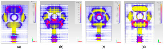
Figure 11.
Surface current distribution of (a) State-1 (ON-ON, 2.4 GHz), (b) State-2 (OFF-ON, 3.27 GHz), (c) State-3 (ON-OFF, 3 GHz), (d) State-4 (OFF-OFF, 3.45 GHz).
In this study, the proposed antenna resembles the conventional monopole antenna structure. However, the working principle of the proposed design is different from the monopole antenna. If the antenna’s working principle is based on the monopole design, the corresponding lengths should be 31.25 mm (for 2.4 GHz), 21.43 mm (for 3.5 GHz), and 25 mm (for 3 GHz), respectively. It is also deduced from Figure 11 that the overall antenna dimension is reduced by incorporating the add-drop ring resonator due to coupling and resonance control.
3.2. Measurement Results
Figure 12 outlines the simulated and measured results for each state separately to examine the antenna performance along with the two different switching mechanisms, namely PIN diode and SPDT. It is clear that such a configuration with PIN diodes is advantageous in terms of ease of integration. However, nonlinear effects of switches, interference losses, and negative effects of biasing lines are disadvantages of electronic reconfigurability. The DC biasing lines required for PIN diodes cause unwanted electromagnetic coupling that may lead to losses and reduced performance. The nonlinear behavior of PIN diodes under varying bias conditions results in signal distortion. These challenges highlight the intricate trade-offs that must be considered when choosing between different reconfigurability approaches. In comparison to SPDT switches, the utilization of PIN diodes for electronic reconfigurability introduces its own set of challenges, mainly due to the DC biasing requirements. While SPDT switches can operate with minimal biasing, PIN diodes need a continuous DC bias current. It is concluded that this bias current not only consumes power but also introduces nonlinear effects, adversely impacting the overall performance of the system.
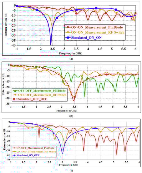
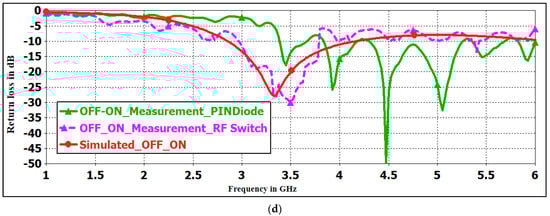
Figure 12.
The comparisons of the simulated and measured reflection coefficients (S11) of the proposed frequency-reconfigurable antenna for the states (a) ON-ON, (b) OFF-OFF, (c) ON-OFF, and (d) OFF-ON.
The frequency-reconfigurable microstrip antenna proposed in this study exhibits variations in return loss across different switch states. This phenomenon arises from the intricate interplay between the antenna’s electromagnetic properties and the presence of switching components, including the PIN diode (BAR64-02V) and SPDT switches (CG2415M6 models). When the PIN diode is in an “ON” state, its additional impedance element alters the effective electrical length of the antenna, resulting in modified resonant frequencies and impedance matching characteristics. This leads to observable variations in the return loss due to the changes in impedance relationships between the antenna and the feeding network. Similarly, the SPDT switches introduce alterations to the antenna’s configuration, affecting its radiating properties and resonance frequencies. Coupling effects between the switching components and the antenna’s inherent geometry further contribute to the observed differences in the return loss. These intricate interactions emphasize the sensitivity of the proposed antenna’s performance to the active switching elements, underscoring the need for precise control and understanding of the switch states for optimal operation.
Measurement of the radiation pattern and gain of a proposed antenna is of paramount importance for performance analysis, including its directional capability, efficiency, tuning, and compliance with various applications. Measuring the radiation pattern and gain of an antenna requires special equipment and techniques such as an antenna test range, turn table, antenna range controller, far field or near field probe, and software. These are some of the primary equipment commonly used in antenna measurement setups. Unfortunately, due to the limitations of the current laboratory facilities, only the reflection coefficient measurement results are given for the designed antenna.
In combination, the ring resonator and switches provide a mechanism for frequency reconfigurability in the antenna. By controlling the states of the switches and the dimensions of the ring resonator, the resonant frequencies and bandwidths of the antenna can be adjusted to meet the requirements of different communication standards, frequency bands, and system specifications. In essence, the proposed antenna design embodies these distinctive features, showcasing a significant leap in the field of versatile and adaptable antennas for wireless communication systems. Through the seamless integration of ring resonators, RF switches, redundancy in operating bands, and an omni-directional radiation pattern, the proposed design represents a notable advancement in addressing the demands of modern communication environments. This allows the antenna to adapt to various operating conditions and optimize its performance in different wireless communication applications. To emphasize the novelty of this antenna, Table 3 is provided to make a comparison with the other frequency-reconfigurable antennas in the literature.
Table 3.
Comparison of the proposed antenna with the literature.
The findings of this study have significant implications for real-world applications and the potential for improving wireless communication in different weather conditions. Firstly, the proposed designs of frequency-reconfigurable antennas incorporating ring resonators and switches offer enhanced functionality, versatility, and adaptability in wireless communication systems. By controlling the states of the switches and the existence of the ring resonator, the resonant frequencies and bandwidths of the antenna can be adjusted, allowing it to adapt to different communication standards, frequency bands, and system requirements. This adaptability is crucial in real-world applications where wireless communication systems need to operate in various frequency bands and environments. The study also highlights the compactness and space-saving nature of the proposed designs, making them suitable for applications with size constraints as tabulated in Table 3. This is particularly important in scenarios where there is limited physical space for antenna installation, such as in small devices or urban environments. Moreover, the integration of ring resonators enables precise frequency control, further enhancing the adaptability and performance optimization of the antenna. This capability is valuable for improving wireless communication in different weather conditions. For example, in adverse weather conditions where signal interference or attenuation may occur, the ability to adjust the resonant frequencies and bandwidths of the antenna can help mitigate the impact of these conditions on wireless communication. Additionally, the study demonstrates the radiation pattern reconfigurability feature of the proposed antenna at different frequencies and angles. This feature can be utilized to optimize the beamforming capability of the antenna, which is crucial for improving wireless communication in different weather conditions. By adjusting the radiation pattern, the antenna can focus the transmitted or received signals in specific directions, enhancing signal strength and reducing the impact of weather-related signal degradation. Overall, the findings of this study open new possibilities for optimizing antenna performance and addressing the challenges associated with frequency reconfigurability in wireless communication systems. The proposed designs offer promising solutions for future wireless communication technologies and have the potential to improve wireless communication in different weather conditions by providing adaptability, compactness, and radiation pattern control.
4. Conclusions
In this study, the novel designs of frequency-reconfigurable antennas incorporating ring resonators in conjunction with PIN diodes or RF switches are presented. These designs enhance the functionality, versatility, and adaptability of frequency-reconfigurable antennas in wireless communication systems. By changing the states of the switching components and with the presence of the ring resonator, precise control over resonant frequencies and bandwidths is achieved, enabling adaptation to various communication standards, frequency bands, and system requirements. The investigation demonstrates the effectiveness of these novel designs in achieving frequency reconfigurability. The antenna exhibits four distinct states, each offering their own resonance frequencies and operating frequency bands. State-1, suitable for mid-band 5G communication systems, operates at 2.4 GHz. State-2, characterized by a resonance frequency of 3.33 GHz, provides a single band characteristic. State-3 exhibits a bandwidth ranging from 2.59 GHz to 3.643 GHz, with a resonance frequency of 3 GHz, making it well-suited for Wi-Fi communication systems. Finally, State-4 covers an operating frequency band ranging from 2.95 GHz to 4.48 GHz. This redundancy in operating bands between State-1 and State-2, and State-3 and State-4, contributes to enhanced reliability. It ensures uninterrupted communication in dynamic wireless environments where interference or changes in the frequency spectrum availability may occur. The antenna can switch between similar states to maintain robust communication links, thereby enhancing overall system reliability. Moreover, the proposed designs offer several practical benefits. The ability to switch between states with similar operating bands can be strategically used to avoid interference from neighboring networks, optimizing the antenna’s performance. Combining the bandwidths covered by similar states can lead to bandwidth expansion, advantageous for high-data-rate applications. The omni-directional radiation pattern characteristics of the antenna enable reliable connectivity in all directions within its coverage area, making it suitable for applications such as Wi-Fi, Bluetooth, IoT, and mid-band 5G. Furthermore, the comprehensive analysis of operating frequencies and radiation patterns demonstrates the antenna’s adaptability to different communication applications. The proposed design controls the resonant behavior of ring resonators via switching components, achieving frequency reconfigurability and adopting various communication standards. This approach contributes to the development of compact, versatile, and high-performance antennas, facilitating efficient wireless communication systems across diverse applications. Overall, the integration of ring resonators and RF switches provides a robust mechanism for achieving frequency reconfigurability in the antenna, allowing it to efficiently adapt to different communication standards and bands. The contributions of this study pave the way for future advancements in the field of frequency-reconfigurable antennas and their applications in wireless communication technologies. The proposed designs offer a promising solution for addressing the challenges of frequency adaptation and enhancing wireless communication capabilities.
Author Contributions
Conceptualization, D.N.G., M.P. and Ş.Ç.; Methodology, Ş.Ç.; Software, D.N.G., M.P. and Ş.Ç.; Validation, D.N.G., M.P. and Ş.Ç.; Formal analysis, Ş.Ç.; Investigation, D.N.G., M.P. and Ş.Ç.; Writing – original draft, D.N.G., M.P. and Ş.Ç.; Writing – review & editing, D.N.G., M.P. and Ş.Ç.; Visualization, D.N.G. and Ş.Ç.; Supervision, M.P. and Ş.Ç.; Project administration, Ş.Ç. All authors have read and agreed to the published version of the manuscript.
Funding
This research received no external funding.
Data Availability Statement
Not applicable.
Acknowledgments
This work is supported by the Scientific Research Projects Unit (BAP) in Adana Alparslan Türkeş Science and Technology University. Project No: 21803003.
Conflicts of Interest
The authors declare no conflict of interest.
References
- Saeed, N.; Bader, A.; Al-Naffouri, T.Y.; Alouini, M.S. When wireless communication responds to covid-19: Combating the pandemic and saving the economy. Front. Commun. Netw. 2020, 1, 566853. [Google Scholar] [CrossRef]
- Abubakar, A.I.; Omeke, K.G.; Ozturk, M.; Hussain, S.; Imran, M.A. The role of artificial intelligence Driven 5G Networks in COVID-19 outbreak: Opportunities, challenges, and future outlook. Front. Commun. Netw. 2020, 1, 575065. [Google Scholar] [CrossRef]
- Akinola, A.; Singh, G.; Ndjiongue, A. Frequency-domain reconfigurable antenna for COVID-19 tracking. Sens. Int. 2021, 2, 100094. [Google Scholar] [CrossRef] [PubMed]
- Shah, I.A.; Hayat, S.; Khan, I.; Alam, I.; Ullah, S.; Afridi, A. A Compact, Tri-Band and 9-Shape Reconfigurable Antenna for Wi-Fi, WiMAX and WLAN Applications. Int. J. Wirel. Microw. Technol. 2016, 6, 45–53. [Google Scholar] [CrossRef]
- Ullah, S.; Ahmad, S.; Khan, B.A.; Flint, J.A. A multi-band switchable antenna for Wi-Fi, 3G Advanced, WiMAX, and WLAN wireless applications. Int. J. Microw. Wirel. Technol. 2018, 10, 991–997. [Google Scholar] [CrossRef]
- Saikia, B.; Dutta, P.; Borah, K. Design of a Frequency Reconfigurable Microstrip Patch Antenna for Multiband Applications. In Proceedings of the 5th International Conference on Computers & Management Skills (ICCM 2019), Arunachal Pradesh, India, 15–16 December 2019. [Google Scholar]
- Bernhard, J.T. Reconfigurable Antennas; Morgan & Claypool Publishers: San Rafael, CA, USA, 2007. [Google Scholar]
- Ali, M. Reconfigurable Antenna Design and Analysis; Artech House: Norwood, MA, USA, 2021. [Google Scholar]
- Sharma, S.K.; Chieh, J.C.S. (Eds.) Multifunctional Antennas and Arrays for Wireless Communication Systems; John Wiley & Sons: Hoboken, NJ, USA, 2021. [Google Scholar]
- Koul, S.K.; Singh, R.K. Reconfigurable Active and Passive Planar Antennas for Wireless Communication Systems; Springer Nature: Berlin/Heidelberg, Germany, 2022. [Google Scholar] [CrossRef]
- Costantine, J.; Tawk, Y.; Barbin, S.E.; Christodoulou, C.G. Reconfigurable antennas: Design and applications. Proc. IEEE 2015, 103, 424–437. [Google Scholar] [CrossRef]
- Li, T.; Zhai, H.; Liang, C.-H. Frequency reconfigurable bow-tie antenna array. Electron. Lett. 2014, 50, 1264–1266. [Google Scholar] [CrossRef]
- Irfan, M.; Khan, W.U.R.; Ullah, S.; Mufti, N.; Khan, M.F.; Ullah, R.; Ali, U.; Muhammad, F.; Althobiani, F.; Alshareef, M.; et al. Cactus-Shaped Frequency Reconfigurable Antenna for Sub 10 GHz Wireless Applications. Comput. Syst. Sci. Eng. 2022, 45, 2693–2704. [Google Scholar] [CrossRef]
- Ahmad, I.; Dildar, H.; Khan, W.U.R.; Shah, S.A.A.; Ullah, S.; Umar, S.M.; Albreem, M.A.; Alsharif, M.H.; Vasudevan, K. Design and Experimental Analysis of Multiband Compound Reconfigurable 5G Antenna for Sub-6 GHz Wireless Applications. Wirel. Commun. Mob. Comput. 2021, 2021, 5588105. [Google Scholar] [CrossRef]
- Qi, Y.; Xu, Y.-H. A Novel Design of Frequency Reconfigurable Antenna for 5G Mobile Terminal Equipment. Int. J. Comput. Commun. Eng. 2020, 9, 134–140. [Google Scholar] [CrossRef]
- Bogale, T.E.; Le, L.B. Beamforming for multiuser massive MIMO systems: Digital versus hybrid ana-log-digital. In Proceedings of the 2014 IEEE Global Communications Conference, Austin, TX, USA, 8–12 December 2014; pp. 4066–4071. [Google Scholar]
- Iqbal, J.; Illahi, U.; Khan, M.A.; Rauf, A.; Ali, E.M.; Bari, I.; Ali, H.; Khan, M.A.; Alibakhshikenari, M.; Dalarsson, M. A Novel Single-Fed Dual-Band Dual-Circularly Polarized Dielectric Resonator Antenna for 5G Sub-6GHz Applications. Appl. Sci. 2022, 12, 5222. [Google Scholar] [CrossRef]
- Kiani, S.H.; Altaf, A.; Anjum, M.R.; Afridi, S.; Arain, Z.A.; Anwar, S.; Khan, S.; Alibakhshikenari, M.; Lalbakhsh, A.; Khan, M.A.; et al. MIMO antenna system for modern 5G handheld devices with healthcare and high rate delivery. Sensors 2021, 21, 7415. [Google Scholar] [CrossRef] [PubMed]
- Illahi, U.; Iqbal, J.; Irfan, M.; Sulaiman, M.I.; Khan, M.A.; Rauf, A.; Bari, I.; Abdullah, M.; Muhammad, F.; Nowakowski, G.; et al. A Novel Design and Development of a Strip-Fed Circularly Polarized Rectangular Dielectric Resonator Antenna for 5G NR Sub-6 GHz Band Applications. Sensors 2022, 22, 5531. [Google Scholar] [CrossRef] [PubMed]
- Xu, H.-X.; Sun, S.; Tang, S.; Ma, S.; He, Q.; Wang, G.-M.; Cai, T.; Li, H.-P.; Zhou, L. Dynamical Control on Helicity of Electromagnetic Waves by Tunable Metasurfaces. Sci. Rep. 2016, 6, 27503. [Google Scholar] [CrossRef]
- Xu, H.-X.; Wang, M.; Hu, G.; Wang, S.; Wang, Y.; Wang, C.; Zeng, Y.; Li, J.; Zhang, S.; Huang, W. Adaptable Invisibility Management Using Kirigami-Inspired Transformable Metamaterials. Research 2021, 2021, 9806789. [Google Scholar] [CrossRef] [PubMed]
- Koziel, S.; Abdullah, M.; Szczepanski, S. Design of High-Performance Scattering Metasurfaces through Optimization-Based Explicit RCS Reduction. IEEE Access 2021, 9, 113077–113088. [Google Scholar] [CrossRef]
- De Smedt, R. Correction due to a finite permittivity for a ring resonator in free space. IEEE Trans. Microw. Theory Tech. 1984, 32, 1288–1293. [Google Scholar] [CrossRef]
- Moradi, B.; Martinez, M.; Fernández-García, R.; Gil, I. Wearable ring resonator antenna. Phys. Status Solidi (A) 2018, 215, 1800410. [Google Scholar] [CrossRef]
- Sreelekshmi, S.; Sankar, S.P. A square ring and single split resonator based wearable antenna for Microwave energy harvesting for IoT nodes. Sustain. Energy Technol. Assess. 2022, 52, 102217. [Google Scholar] [CrossRef]
- Jain, P.; Chhabra, H.; Chauhan, U.; Prakash, K.; Gupta, A.; Soliman, M.S.; Islam, S.; Islam, M.T. Machine learning assisted hepta band THz metamaterial absorber for biomedical applications. Sci. Rep. 2023, 13, 1792. [Google Scholar] [CrossRef]
- Wu, X.; Zheng, Y.; Luo, Y.; Zhang, J.; Yi, Z.; Wu, X.; Cheng, S.; Yang, W.; Yu, Y.; Wu, P. A four-band and polarization-independent BDS-based tunable absorber with high refractive index sensitivity. Phys. Chem. Chem. Phys. 2021, 23, 26864–26873. [Google Scholar] [CrossRef]
- Li, Y.; Chen, X.; Hu, F.; Li, D.; Teng, H.; Rong, Q.; Zhang, W.; Han, J.; Liang, H. Four resonators based high sensitive terahertz metamaterial biosensor used for measuring concentration of protein. J. Phys. D Appl. Phys. 2019, 52, 095105. [Google Scholar] [CrossRef]
- Wang, G.-D.; Liu, M.-H.; Hu, X.-W.; Kong, L.-H.; Cheng, L.-L.; Chen, Z.-Q. Multi-band microwave metamaterial absorber based on coplanar Jerusalem crosses. Chin. Phys. B 2014, 23, 017802. [Google Scholar] [CrossRef]
- Meng, H.-Y.; Wang, L.-L.; Zhai, X.; Liu, G.-D.; Xia, S.-X. A Simple design of a multi-band terahertz metamaterial absorber based on periodic square metallic layer with T-shaped gap. Plasmonics 2017, 13, 269–274. [Google Scholar] [CrossRef]
- Zhao, L.; Liu, H.; He, Z.; Dong, S. Theoretical design of twelve-band infrared metamaterial perfect absorber by combining the dipole, quadrupole, and octopole plasmon resonance modes of four different ring-strip resonators. Opt. Express 2018, 26, 12838–12851. [Google Scholar] [CrossRef] [PubMed]
- Meng, K.; Park, S.J.; Burnett, A.D.; Gill, T.; Wood, C.D.; Rosamond, M.; Li, L.H.; Chen, L.; Bacon, D.R.; Freeman, J.R.; et al. Increasing the sensitivity of terahertz split ring resonator metamaterials for dielectric sensing by localized substrate etching. Opt. Express 2019, 27, 23164–23172. [Google Scholar] [CrossRef] [PubMed]
- Jain, P.; Chhabra, H.; Chauhan, U.; Singh, D.K.; Anwer, T.M.K.; Ahammad, S.H.; Hossain, A.; Rashed, A.N.Z. Multiband Metamaterial absorber with absorption prediction by assisted machine learning. Mater. Chem. Phys. 2023, 307, 440–445. [Google Scholar] [CrossRef]
- Wang, Y.; Sun, T.; Paudel, T.; Zhang, Y.; Ren, Z.; Kempa, K. Metamaterial-Plasmonic Absorber Structure for High Efficiency Amorphous Silicon Solar Cells. Nano Lett. 2011, 12, 440–445. [Google Scholar] [CrossRef]
- Zhang, X.; Liu, Z. Superlenses to overcome the diffraction limit. Nat. Mater. 2008, 7, 435–441. [Google Scholar] [CrossRef]
- Jain, P.; Prakash, K.; Sardana, N.; Kumar, S.; Gupta, N.; Singh, A.K. Design of an ultra-thin hepta-band metamaterial absorber for sensing applications. Opt. Quantum Electron. 2022, 54, 569. [Google Scholar] [CrossRef]
- Jain, P.; Thourwal, A.; Bansal, S.; Gupta, N.; Kumar, S.; Singh, A.K.; Samanta, S.; Sardana, N. T-shaped resonator for X-band applications. In Proceedings of the 2017 IEEE MTT-S International Microwave and RF Conference (IMaRC), Ahmedabad, India, 11–13 December 2017; pp. 1–5. [Google Scholar]
- Shen, X.; Cui, T.J.; Zhao, J.; Ma, H.F.; Jiang, W.X.; Li, H. Polarization-independent wide-angle triple-band met-amaterial absorber. Opt. Express 2011, 19, 9401–9407. [Google Scholar] [CrossRef]
- Janneh, M.; De Marcellis, A.; Palange, E.; Tenggara, A.T.; Byun, D. Design of a metasurface-based dual-band Terahertz perfect absorber with very high Q-factors for sensing applications. Opt. Commun. 2018, 416, 152–159. [Google Scholar] [CrossRef]
- Wang, B.-X.; Wang, G.-Z. New Type Design of the triple-band and five-band metamaterial absorbers at terahertz frequency. Plasmonics 2017, 13, 123–130. [Google Scholar] [CrossRef]
- Ojaroudi Parchin, N.; Jahanbakhsh Basherlou, H.; Al-Yasir, Y.I.; MAbdulkhaleq, A.; AAbd-Alhameed, R. Recon-figurable antennas: Switching techniques—A survey. Electronics 2020, 9, 336. [Google Scholar] [CrossRef]
- Clemente, A.; Dussopt, L.; Sauleau, R.; Potier, P.; Pouliguen, P. 1-bit reconfigurable unit cell based on PIN diodes for trans-mit-array applications in x-band. IEEE Trans. Antennas Propag. 2012, 60, 2260–2269. [Google Scholar] [CrossRef]
- Mun, B.; Jung, C.; Park, M.-J.; Lee, B. A compact frequency-reconfigurable multiband lte MIMO antenna for laptop applications. IEEE Antennas Wirel. Propag. Lett. 2014, 13, 1389–1392. [Google Scholar] [CrossRef]
- Rabus, D.G. Integrated Ring Resonators; Springer: Berlin/Heidelberg, Germany, 2007. [Google Scholar]
- Yariv, A. Critical coupling and its control in optical waveguide-ring resonator systems. IEEE Photon-Technol. Lett. 2002, 14, 483–485. [Google Scholar] [CrossRef]
- Yariv, A. Universal relations for coupling of optical power between microresonators and dielectric wave-guides. Electron. Lett. 2000, 36, 321–322. [Google Scholar] [CrossRef]
- California Eastern Laboratories. L, S-Band High Power SPDT RF Switch CG2415M6 Datasheet. Available online: https://www.cel.com/documents/datasheets/CG2415M6.pdf (accessed on 7 September 2017).
- Jin, G.; Deng, C.; Yang, J.; Xu, Y.; Liao, S. A New Differentially-Fed Frequency Reconfigurable Antenna for WLAN and Sub-6GHz 5G Applications. IEEE Access 2019, 7, 56539–56546. [Google Scholar] [CrossRef]
- Coll-Perales, B.; Gozalvez, J.; Gruteser, M. Sub-6GHz Assisted MAC for Millimeter Wave Vehicular Communications. IEEE Commun. Mag. 2019, 57, 125–131. [Google Scholar] [CrossRef]
- Zaidi, A.; Awan, W.A.; Hussain, N.; Baghdad, A. A Wide and Tri-band Flexible Antennas with Independently Controllable Notch Bands for Sub-6-GHz Communication System. Radioengineering 2020, 29, 44–51. [Google Scholar] [CrossRef]
- Cai, Y.-M.; Li, K.; Yin, Y.; Gao, S.; Hu, W.; Zhao, L. A Low-profile frequency reconfigurable grid-slotted patch antenna. IEEE Access 2018, 6, 36305–36312. [Google Scholar] [CrossRef]
- Soltanpour, M.; Fakharian, M. Compact filtering slot antenna with frequency agility for Wi-Fi/LTE mobile applications. Electron. Lett. 2016, 52, 491–492. [Google Scholar] [CrossRef]
- Han, L.; Wang, C.; Chen, X.; Zhang, W. Compact frequency-reconfigurable slot antenna for wireless applications. IEEE Antennas Wirel. Propag. Lett. 2016, 15, 1795–1798. [Google Scholar] [CrossRef]
- Abdulraheem, Y.I.; Oguntala, G.A.; Abdullah, A.S.; Mohammed, H.J.; Ali, R.A.; Abd-Alhameed, R.A.; Noras, J.M. Design of frequency reconfigurable multiband compact antenna using two PIN diodes for WLAN/WiMAX applications. IET Microw. Antennas Propag. 2017, 11, 1098–1105. [Google Scholar] [CrossRef]
- Ghaffar, A.; Li, X.J.; Awan, W.A.; Naqvi, S.I.; Hussain, N.; Seet, B.-C.; Alibakhshikenari, M.; Falcone, F.; Limiti, E. Design and Realization of a Frequency Reconfigurable Multimode Antenna for ISM, 5G-Sub-6-GHz, and S-Band Applications. Appl. Sci. 2021, 11, 1635. [Google Scholar] [CrossRef]
- Shah, I.A.; Hayat, S.; Basir, A.; Zada, M.; Shah, S.A.A.; Ullah, S. Design and Analysis of a Hexa-Band Frequency Recon-Figurable Antenna for Wireless Communication. AEU-Int. J. Electron. Commun. 2019, 98, 80–88. [Google Scholar] [CrossRef]
Disclaimer/Publisher’s Note: The statements, opinions and data contained in all publications are solely those of the individual author(s) and contributor(s) and not of MDPI and/or the editor(s). MDPI and/or the editor(s) disclaim responsibility for any injury to people or property resulting from any ideas, methods, instructions or products referred to in the content. |
© 2023 by the authors. Licensee MDPI, Basel, Switzerland. This article is an open access article distributed under the terms and conditions of the Creative Commons Attribution (CC BY) license (https://creativecommons.org/licenses/by/4.0/).