1. Introduction
Large concrete dams are crucial infrastructures generating backbone energy power and controlling water resource distribution. The earthquake safety of those structures is an important issue, since damaged large dams have an extremely negative impact on social and economic systems across a sizable region, and often those damages are irrecoverable. Especially, the possibility of sliding during an earthquake is important in the safety assessment of a concrete gravity dam, in that sliding can cause the total failure of a dam [
1,
2].
To quantify the chance of sliding as a whole dam structure, the concept of the Sliding Safety Factor (SSF) has been used widely [
3,
4]. The SSF of a dam is generally defined as the ratio between the shear strength of the dam–foundation interface and the external shear force applied to the interface. The shear strength consists of the cohesive force, and the multiplication of the vertical force and the coefficient of the internal friction. When the external force exceeds the shear strength, in which the SSF is lower than unity, a dam possibly slides. Since this definition of SSF is straightforward, major dam agents including USACE and USBR have used them to evaluate the sliding stability of their dams [
5,
6]. However, the conventional SSF formulation cannot explain the sliding stability along the dam–foundation interface, since it does not take into account the fractured area in the interface [
7,
8]. A concrete gravity dam usually has a pre-existing fractured area due to the hydraulic pressure at the heel area and/or past earthquakes [
9,
10]. In addition, when a dam is subjected to strong earthquakes, the fracture initiates and gradually propagates at the bottom of a dam [
10,
11,
12]. These pre-existing and progressive fractures reduce the resistant shear strength against the external shear force [
13,
14,
15,
16]. Hence, if the fractured area is not considered in the SSF evaluation, the shear strength can be exaggerated against sliding, and this would have an adverse impact on the precision of the sliding safety evaluation. The existing conventional SSF is not able to describe these important situations for the sliding stability of a dam.
To overcome the shortcomings, an improved SSF has been proposed to consider the fractured area in the dam–foundation interface [
17,
18], where the resistant shear forces at the undamaged area and the fractured area are determined separately. However, in the improved SSF formulation, the total vertical force is decomposed in proportion to the ratio of those areas for simplicity, which produces inaccurate results in dynamic analysis of a dam. In addition, the effect of fracture progression is not considered important in this improved SSF, as well as in the conventional SSF.
In this study, a new SSF is suggested to take account of the progressive fractured area at the dam–foundation interface. In order to use the suggested SSF, a contact and sliding model for the dam–foundation system is required to compute the dynamically varying normal forces and sliding motions, which is presented in the context of the finite element method. To investigate the effect of the fractured area progression on the sliding safety evaluation, the conventional, improved, and newly suggested SSFs were computed using the dynamic earthquake analysis results of a concrete gravity dam subjected to two artificial earthquakes. After comparing the SSF values, there is a discussion about the possibility that the conventional SSF significantly overestimates the resistant capacity of a dam against sliding, and about the importance of an appropriate SSF formulation.
2. Dam Sliding Model
2.1. Conventional and Improved Sliding Safety Factors
To evaluate the dynamic sliding stability of concrete gravity dams subjected to earthquakes, the concept of Sliding Safety Factor (SSF) has been used as the ratio of the shear strength to the shear force on a dam tending to slide along its base [
3]. When the SSF is larger than unity during the entire duration of an earthquake, it is supposed that the dam structure is stable against rigid-body sliding. The conventional formulation of the SSF is defined as:
where
is the cohesive strength of the dam–foundation interface,
A is the total area of the dam bottom face,
is the total vertical force at the dam base as a function of time
t,
is the internal friction angle of the dam–foundation interface, and
V is the absolute value of the external shear force along the dam base, which is also a function of time
t. This sliding criterion represents a simple ratio between the shear strength of the interface at the dam base and the force to slide a dam body.
Although, mainly due to its simplicity, the SSF in Equation (1) is popularly used in static and dynamic stability evaluation, it only accounts for the sliding stability of a dam under the assumption of undamaged dam–foundation interface, and becomes inaccurate or invalid once the fracture propagates along the dam–foundation interface.
To address this problem, the improved SSF has been proposed [
17,
18]. In the formulation, it is considered that the total shear strength of the interface area is divided into two parts, the shear strength of the undamaged area and one from the fractured (so, damaged) area. Each of them follows Coulomb’s friction law with different friction angles, and the SSF is written as:
where
is the ratio of the damaged area to
A, the total area of the dam bottom face,
is the vertical force at the dam–foundation interface,
is the internal friction of the undamaged interface region, and
is the coulomb friction angle along the fractured surface of the dam–foundation interface. While the internal friction angle is a material property [
19], the coulomb friction angle,
, represents the surface friction caused by roughness and interlocking along the fractured dam–foundation interface. The ratio
is assumed to be constant to represent a pre-existing fractured region caused by strong uplift hydro-pressure or a preceding earthquake. In Equation (2), it is assumed that the total vertical force at the dam base is divided into the undamaged and the fractured region components in proportion to the ratio of their areas. When a structure is dynamically excited with horizontal and vertical loads, the vertical reaction at its base region cannot be decomposed in proportion to subregional areas. Hence, the vertical force of each area should be evaluated separately for the precise frictional force computation.
2.2. New Sliding Safety Factor
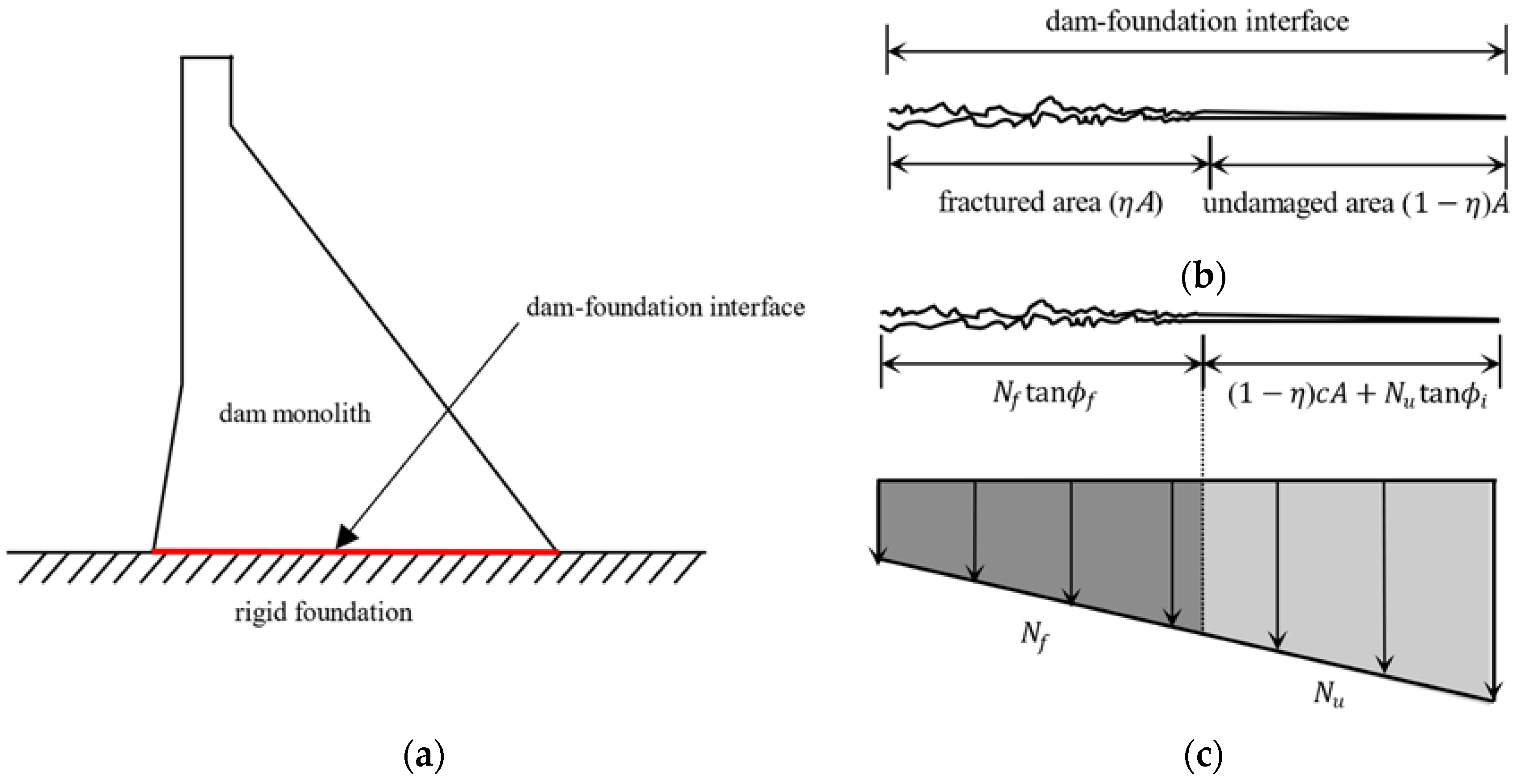
In
Figure 1, a dam–foundation system having a partially fracture-damaged condition at the dam base interface is depicted. Assuming that the fractured area exists as shown in
Figure 1b, the total normal force against the external force is the sum of the normal forces at the undamaged and the fractured areas. However, since the normal force distribution is not uniform, as shown in
Figure 1c, the normal force cannot be simply calculated in consideration of the ratio of the fractured area [
20,
21]. In
Figure 1c, it is shown that the magnitude of the vertical force at the toe is larger than the vertical force at the heel, and the distribution varies with time. When a dam is subjected to real earthquakes, the actual distribution of the vertical force will be more irregular.
The engineering guideline of FERC [
20] states that the cohesion of the fractured concrete–rock foundation interface should be assumed to be zero. Also, CDA [
22] specifies that the cohesion is assumed to be considered within an undamaged concrete structure. Hence, it is reasonable that the cohesive strength in SSF evaluation vanishes to zero at the damaged area where the fracture is severely developed, which is already applied in Equation (2).
While the ratio of the damaged area to the total area,
, is given as a fixed value in Equation (2), for realistic evaluation of the sliding stability of a concrete dam, it is more reasonable that
varies with time as the fracture progresses along the dam–foundation interface. Considering those observations, a modified formulation of SSF is suggested in this study as:
where
is the vertical force at the undamaged area,
is the vertical force at the fractured area. In Equation (3), it is noted that
,
and
, as well as
are functions of time. It is also noted that the two vertical forces,
and
in Equation (3), are computed by a nonlinear finite element analysis considering the nonlinearity of sliding-contact problems, described in
Section 2.3, while those vertical forces are inaccurately assumed as the linear proportions of the area,
and
, respectively, in Equation (2). To evaluate the suggested SSF, a contact–sliding model for the dam–foundation interface is necessary for the computation of the fractured area and corresponding vertical forces, which is explained in the following section.
2.3. Interface Contact–Sliding Model
A contact and sliding model for the dam–foundation interface is implemented in the context of the finite element mesh. In this study, it is assumed that the pre-existing or newly generated fracture propagates along the dam–foundation interface plane and the propagation criterion is dominated by the shear mode (mode II) fracture. In addition, the dam base and its corresponding rock-foundation surfaces are assumed to contact and separate vertically along the fractured region.
The dam side of the interface is defined as a slave surface and the foundation side is defined as a master surface. The fracture extension starts from the heel of a dam, since the crack initiation occurs from the heel of a dam due to the hydraulic pressure. The contact surface is defined by the vertical direction and the horizontal direction. As shown in
Figure 2, in the vertical direction, mesh penetration between the master and slave surface is controlled [
23]. The principle of minimum total potential energy, which is the basis of the finite element method, is applied to the dam–foundation contact model. The basic form of the principle can be represented as:
where
is the total potential energy,
is the strain energy,
is the work done by the external force. Equation (4) is applied to the contact constraint in the vertical direction that controls mesh penetration. The contact constraint is formed by the Lagrange multiplier method and virtual work as:
where
is the clearance between contact interfaces,
is the pressure delivered through the interfaces. Equation (6) shows that the pressure delivered through the interface is zero when there is a positive clearance between the foundation (master) and dam base (slave) surfaces. In case of zero clearance, it is defined that the foundation and dam base surfaces are regarded as contacted and the contact pressure can be delivered through the interface as shown in Equation (7).
In the horizontal direction, the fracture progression along the dam–foundation interface is modeled by the stick–slip phenomenon. The Lagrange multiplier method is applied to the minimum total potential energy principle to enforce exact stick–slip conditions [
23]. In the
-th iteration, the augmented virtual work can be expressed as:
where
is the friction force at the interface,
is the sliding displacement,
is the Lagrange multiplier, and
is the interface surface region. In the stick state, when the external shear force
exceeds the friction force
, the state is changed to sliding as shown in Equation (9). Meanwhile, Equation (10) shows that if the direction of the friction force and the direction of sliding are opposite in the sliding state, the state is changed to stick.
By this mechanism, the dam–foundation model follows exact stick–slip conditions. The relationship between stress and strain is depicted in
Figure 3. Here, the critical shear force
is the sum of the cohesive forces and the frictional forces of the interface, which is the same as the numerator in Equation (3). There is no additional sliding in the stick state (
. When the absolute value of an external shear force exceeds the critical shear force, the existing state is changed to sliding.
3. Numerical Analysis
3.1. Finite Element Model for a Concrete Gravity Dam
To verify the validity of the proposed SSF in Equation (3) and compare it with the other SSF formulations in Equations (1) and (2), the seismic analysis of a 70 m concrete gravity dam is performed as depicted in
Figure 4. The dam is modeled by a finite element program, Abaqus. The model consists of 685 eight-node isoparametric plane stress elements. The concrete properties are the elastic modulus
= 28.1 GPa, Poisson’s ratio
= 0.12, and the density
= 2300 kg/
. The cohesive force of the concrete is suggested to be 10 percent of its compressive strength. The compressive strength of the concrete is from 20.7 MPa to 34.5 MPa [
24]. In this study, the cohesive force of the concrete dam–foundation interface is assumed as 2.07 MPa, which is 10 percent of the minimum compressive strength. The friction coefficients
and
are derived from USACE [
25] and ACI [
26]. According to USACE [
25], the coefficient of the internal friction
is set as 0.7. In ACI [
26], the coulomb friction coefficient
is prescribed as 0.6.
The hydrostatic and hydrodynamic pressures are applied, and the uplift pressure is ignored in this numerical analysis to avoid unnecessary complexity. The hydrodynamic pressure is applied according to the simplified added-mass formulation of Westergaard [
27], defined as:
where
is the added mass acting as the hydrodynamic pressure,
is the density of water,
is the depth of the upstream reservoir,
is the vertical height from the surface of water, and
is the area per vertical height.
3.2. Test Cases
There are three different models used for tests, as shown in
Table 1: Case 1 is the dam–foundation single-body model, which assumes the undamaged state of the dam. Case 2 is the dam–foundation contact model with a fixed pre-existing fractured area at the upstream dam base, as depicted in
Figure 1b. Case 3 is the dam–foundation contact model with a pre-existing fractured area which can be dynamically propagated along its entire dam–foundation interface to the downstream toe. In Cases 2 and 3, pre-existing fractures at the dam base are set to consider the strong hydraulic pressure or earthquakes of the past. The initial ratio of the fractured area to the total area of the dam base is assumed as 50 percent in Cases 2 and 3. Before being fractured, the undamaged area resists against the external force by the shear strength of the dam–foundation interface. After being fractured, the resistant force against the external force follows Coulomb’s friction law.
In
Table 2, there is a list of Peak Ground Acceleration (PGA) data from the recent strong earthquakes [
28,
29,
30]. The highest PGA of an earthquake is 3 g and the lowest one is 0.5 g. In this study, two artificial earthquakes are used, in which the PGAs are 0.64 g and 0.7 g, respectively, as depicted in
Figure 5. The effective duration of Artificial earthquake I is 15 s and Artificial earthquake II is 20 s.
3.3. Response Results
In
Figure 6, horizontal crest displacement of the upstream side from the bottom of the dam and the sliding displacement in Case 3 are shown when the dam is subjected to Artificial earthquakes I and II. Positive values indicate the downstream direction. Since the dam–foundation interfaces are fixed in Cases 1 and 2, the crest displacement and stress distributions of Cases 1 and 2 are mostly identical. However, the SSFs in Cases 1 and 2 are different, and this is described in
Section 4.
There is a difference in the crest displacement between Cases 1 and 3 due to the progressive fractured area. There is no sliding in Case 1, whereas the sliding behavior is included in Case 3. When the sliding behavior is observed, the energy dissipation caused by the sliding friction occurs. The crest displacement in Case 3 is affected by the energy dissipation and its amplitude of the crest displacement is relatively smaller than the crest displacement of Case 1 when the sliding behavior is observed. While the sliding behavior is not observed, the crest displacement in Case 3 is mostly identical to the crest displacement in Case 1. Relative displacement contours from the bottom of the dam in Cases 1 and 3 when the largest sliding displacement is observed are shown in
Figure 7. According to
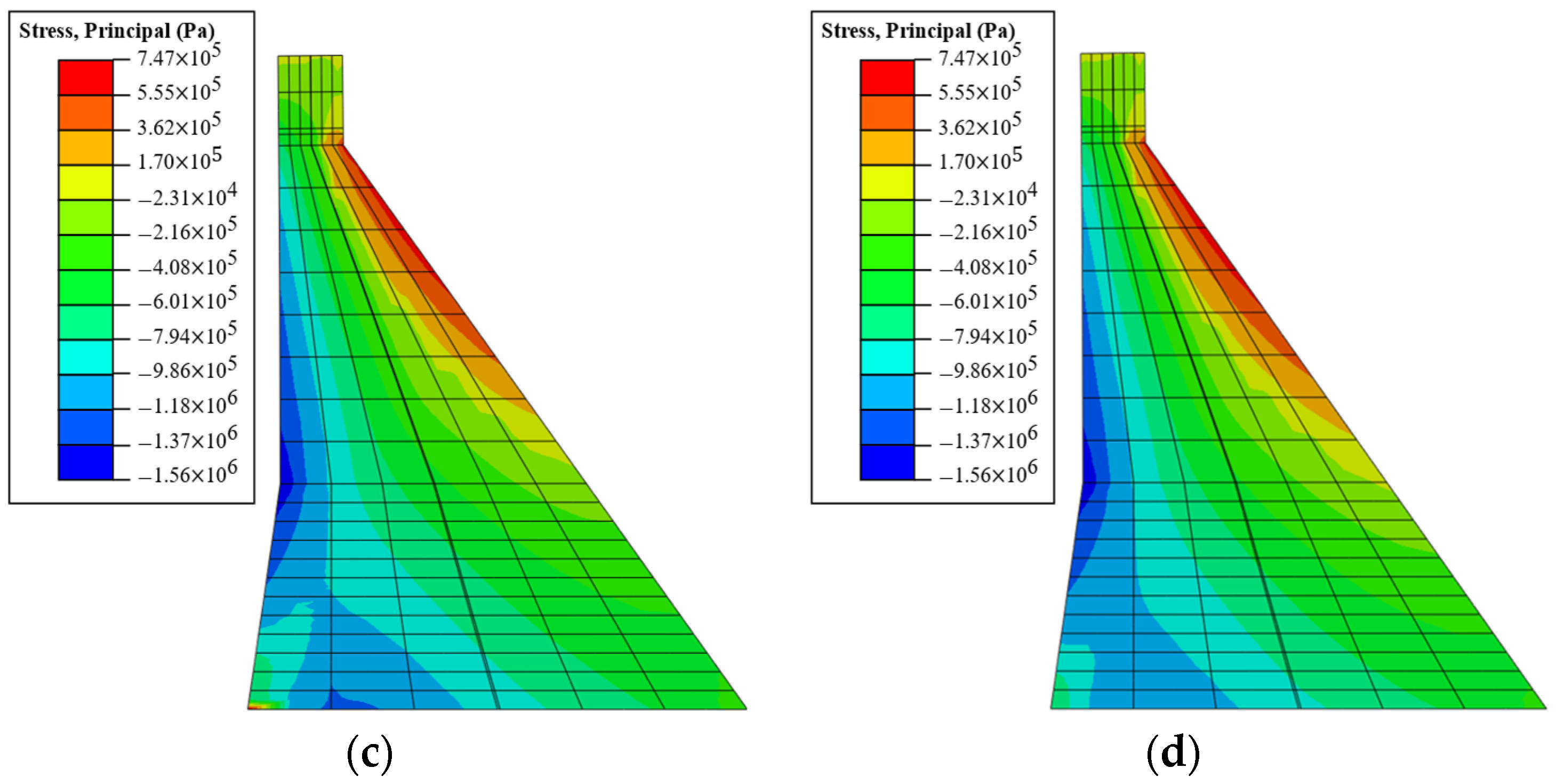
Figure 7, the sliding behavior affects the overall crest displacement. The overall crest displacement in Case 1 is larger than the crest displacement in Case 3. Also, the difference in the stress distribution can be observed in
Figure 8, which depicts the tensile principal stress distribution in Cases 1 and 3. Compared with Case 1, the overall principal stress values in Case 3 are smaller due to energy dissipation from the sliding.
Sliding is the main source of nonlinearity in this study, since the effects of the rocking and the deformation at the bottom of the dam on the sliding behavior of a concrete dam are negligible compared to the effect of the base sliding [
31,
32]. In
Figure 6, it can be observed that sliding displacements at the heel and toe of the dam are nearly identical and coincide with each other in the plot. Hence, it is justified that the rocking and the local deformation of the bottom of a dam can be ignored in sliding analysis.
4. SSF Evaluation
In
Figure 9 and
Figure 10, reciprocal values of the SSF and the lowest SSF (or highest reciprocal of SSF) point at each test case are shown when the dam model is subjected to Artificial earthquakes I and II. In this study, the reciprocal of the SSF is used in the plot rather than SSF values in order to avoid unimportant high peak values of the SSF generated by the nearly zero external shear force. The red dashed line denotes where the SSF is unity, which indicates the threshold for sliding of a dam structure.
In Case 1, the cohesive force is applied to the overall dam–foundation interface. In Case 2, the cohesive force is only applied to the undamaged area. In Case 3, the cohesive force is also applied to the undamaged area, and when the SSF is below unity, it is considered that the dam–foundation interface is fractured, and the cohesive force decreases to zero. In
Figure 9, the lowest SSF of Case 1 is 2.070, Case 2 is 1.548, and Case 3 is 0.413, while in
Figure 10, the lowest SSF of Case 1 is 2.227, Case 2 is 1.658, and Case 3 is 0.442. The SSF of Case 3 is relatively lower than Cases 1 and 2, since, in the newly fractured region during the fracture propagation, the cohesive force is considered to be zero, the coefficient of the internal friction changes to the coulomb friction coefficient,
, and consequently, the friction force and SSF decrease. Depending on the ratio of the fractured area, the resistant force against the external force highly changes.
According to the results in
Table 3, for both artificial earthquakes, the minimums of the SSF in Case 2 are about 75 percent of those in Case 1. Furthermore, the minimums of the SSF in Case 3 show much smaller values, about 20 percent of those in Case 1. Considering that partial fractures at a dam base can exist due to the hydraulic pressure acting at the upstream heel and/or past earthquakes, the SSF in Equation (1), which is widely used as a sliding criterion, significantly overestimates the sliding stability of a dam. It is noted that Cases 1 and 2 show safety satisfaction if unity is used for the safety factor threshold, while only Case 1 passes the sliding safety condition if the safety factor becomes two. The SSF formulation, Equation (3), used in Case 3 produces no satisfaction for the unity safety threshold, which means the other two SSFs possibly result in incorrect judgements on sliding safety.
5. Discussion
In this study, it is verified that considering the fractured area and its progressive modeling at the dam–foundation interface is crucial in the sliding safety evaluation of a concrete gravity dam. In the numerical analysis study, the conventional formulation of the SSF, in which the fractured area is not represented at all, shows extremely overestimated sliding safety judgements when a dam is subjected to strong earthquakes. This SSF formulation results in about five times safer side values than those evaluated by the newly suggested SSF formulation with initial and progressive fractures, which is based on a more realistic fracture-progress model. The so-called improved SSF formulation, with the fixed fractured area and simplified computation of the vertical force at the fractured area, also shows more than three times safer side values than those by the suggested SSF formulation. Consequently, it can be observed that those existing SSF formulations could provide wrongfully safe judgements on sliding stability checks, which implies that those SSFs possibly exaggerate the sliding safety of dams.
From the numerical simulation, it is shown that the proposed contact–sliding model can reproduce fracture propagation along the dam–foundation interface, which is expected during strong earthquake ground motions, including the two artificial earthquakes used in the present numerical study. In the simulation results, the progressive fracture propagation realistically starts and stops according to the intensity of ground motions. It was observed in the simulation that the concrete gravity dam, subjected to a strong earthquake, slides monotonically toward the downstream due to the reservoir hydrostatic pressure. It is also noted that the fracture rapidly propagates through the entire interface immediately after the dam starts to slide. From these observations, it can reasonably be deduced that it is essential to use an appropriate contact–sliding model for the fracture propagation in an accurate evaluation of the sliding safety for concrete gravity dams. Otherwise, the shear resistance capacity against sliding can become significantly overestimated, as aforementioned in this section. The newly suggested SSF with the proposed contact–sliding model for the dam–foundation interface shows more accurate and conservative sliding safety evaluation results compared to the two existing conventional SSF formulations, since the degradation of the overall shear strength along the dam–foundation interface can be realistically represented in the dam–foundation model and its SSF evaluation.
Although, in this study, the uplift pressure acting along the interface fracture is ignored to avoid complexity, its effects on the SSF evaluation can be significant. The uplift force reduces the vertical forces, which results in weakening the frictional shear resistance forces. Additionally, it can cause mode I fracture propagation with other upward forces acting on the dam body. Since the dynamic distribution of the uplift pressure and its effect on the mode I and/or mixed mode fracture of a concrete dam–foundation interface are quite different from the static one, they remain undergoing research topics, and their impacts on the SSF evaluation should be addressed in a future study.
6. Conclusions
In the present study, it is suggested to use the Sliding Safety Factor (SSF) while considering pre-existing and progressive fractures along the dam foundation to evaluate the sliding safety of a concrete gravity dam subjected to strong earthquakes. In order to use the suggested SSF, it is necessary to implement an appropriate contact and sliding model in the dynamic earthquake analysis, like the one described in this study. This newly suggested SSF with the proposed contact–sliding model provides more realistic and accurate sliding safety factors by considering fracture progression. As a result, it can help avoid suppositional and ambiguous safety factor criteria in dam safety judgements, which will contribute to advances in concrete gravity dam design and evaluation technology. It is also suggested that if the conventional SSF formulation, or its simply improved version, is unavoidably used for a safety analysis, the safety judgement must be made cautiously, taking into account the possibility and impact of fracture progression.
In the current study, it is assumed that the fracture at the dam–foundation interface moves along the interface plane and that the fracture propagation is dominated by the shear force, for simplicity. Although this assumption still gives reasonable and practical results, further studies are needed that include the tensile mode fracture, as well as the shear mode fracture and more general fracture propagation surfaces other than simple planes into the SSF evaluation. Moreover, in order to validate and enhance the suggested model, on-site measurement studies for the sliding displacement of concrete gravity dams subjected to strong ground motions are desirable in future research.
Author Contributions
Conceptualization, J.L.; Data curation, J.L. and H.S.L.; Formal analysis, H.S.L.; Funding acquisition, J.L.; Investigation, J.L. and H.S.L.; Methodology, J.L. and H.S.L.; Project administration, J.L.; Resources, J.L.; Software, H.S.L.; Validation, J.L.; Writing—original draft, J.L. and H.S.L.; Writing—review and editing, J.L. All authors have read and agreed to the published version of the manuscript.
Funding
This research was supported by the Basic Science Research Program through the National Research Foundation of Korea (NRF), funded by the Ministry of Education (NRF-2018R1D1A1B07051141).
Institutional Review Board Statement
Not applicable.
Informed Consent Statement
Not applicable.
Data Availability Statement
Data sharing is not applicable to this article.
Acknowledgments
This work was supported by the Dongguk University Research Fund of 2023.
Conflicts of Interest
The authors declare no conflict of interest.
References
- Wang, S.; Xu, B.; Zhu, Z.; Li, J.; Lu, J. Reliability Analysis of Concrete Gravity Dams Based on Least Squares Support Vector Machines with an Improved Particle Swarm Optimization Algorithm. Appl. Sci. 2022, 12, 12315. [Google Scholar] [CrossRef]
- Chávez, J.W.; Fenves, G.L. Earthquake response of concrete gravity dams including base sliding. J. Struct. Eng. 1995, 121, 865–875. [Google Scholar] [CrossRef]
- Henry, D.C. Stability of straight Concrete Gravity Dams. Trans. ASCE 1933, 99, 1041–1061. [Google Scholar]
- Nicholson, G.A. Design of Gravity Dams on Rock Foundations: Sliding Stability Assessment by Limit Equilibrium and Selection of Shear Strength Parameters; Technical Report GL-83-13; Army Engineer Waterways Experiment Station: Vicksburg, MS, USA, 1983. [Google Scholar]
- Headquarters, U.S. Army Corps of Engineers. Stability Analysis of Concrete Structures; EM 1110-2-2100; U.S. Army Corps of Engineers: Washington, DC, USA, 2005. [Google Scholar]
- Duncan, W.; Huntley, C.; Hokenstrom, J.; Cudworth, A.; McDaniel, T. Design of Small Dams. A Water Resources Technical Publication; Final Report, No. PB-95-176368/XAB; U.S. Bureau of Reclamation: Denver, CO, USA, 1987; pp. 328–329. [Google Scholar]
- Saichi, T.; Renaud, S.; Bouaanani, N.; Miquel, B. Effects of rock foundation roughness on the sliding stability of concrete gravity dams based on topographic surveys. J. Eng. Mech. 2019, 145, 04019043. [Google Scholar] [CrossRef]
- Wang, X.H.; Zhang, S.R.; Dai, J.G.; Wang, C. Evaluation of base damage and stability of concrete gravity dam subjected to underwater explosion. Structures 2022, 38, 1502–1514. [Google Scholar] [CrossRef]
- Bolzon, G. Collapse mechanisms at the foundation interface of geometrically similar concrete gravity dams. Eng. Struct. 2010, 32, 1304–1311. [Google Scholar] [CrossRef]
- Alliard, P.M.; Léger, P. Earthquake safety evaluation of gravity dams considering aftershocks and reduced drainage efficiency. J. Eng. Mech. 2008, 134, 12–22. [Google Scholar] [CrossRef]
- Krounis, A.; Johansson, F.; Larsson, S. Effects of spatial variation in cohesion over the concrete-rock interface on dam sliding stability. J. Rock Mech. Geotech. Eng. 2015, 7, 659–667. [Google Scholar] [CrossRef]
- Li, J.B.; Gao, X.; Fu, X.A.; Wu, C.; Lin, G. A nonlinear crack model for concrete structure based on an extended scaled boundary finite element method. Appl. Sci. 2018, 8, 1067. [Google Scholar] [CrossRef]
- Sas, G.; Popescu, C.; Bista, D.; Seger, A.; Arntsen, B.; Johansson, F.; Lia, L. Influence of large-scale asperities on the shear strength of concrete-rock interface of small buttress dams. Eng. Struct. 2021, 245, 112952. [Google Scholar] [CrossRef]
- Krounis, A.; Johansson, F.; Spross, J.; Larsson, S. Influence of cohesive strength in probabilistic sliding stability reassessment of concrete dams. J. Geotech. Geoenviron. Eng. 2017, 143, 04016094. [Google Scholar] [CrossRef]
- Javanmardi, F.; Léger, P.; Tinawi, R. Seismic structural stability of concrete gravity dams considering transient uplift pressures in cracks. Eng. Struct. 2005, 27, 616–628. [Google Scholar] [CrossRef]
- Arabshahi, H.; Lotfi, V. Earthquake response of concrete gravity dams including dam–foundation interface nonlinearities. Eng. Struct. 2008, 30, 3065–3073. [Google Scholar] [CrossRef]
- Lo, K.Y.; Ogawa, T.; Lukajic, B.; Tsui, K.K.; Wang, S. Evaluation of strength parameters of concrete-rock interface for dam safety assessment. In Proceedings of the Canadian Dam Safety Conference, Toronto, ON, Canada, 18–19 September 1990; pp. 71–93. [Google Scholar]
- Dawson, R.V.; Curtis, D.D.; Donnelly, R.C. Sliding Resistance of Concrete Gravity Dams; CEA No. 9331 G 2002; Canadian Electricity Association Technologies Inc.: Montreal, QC, Canada, 1998. [Google Scholar]
- Fronteddu, L.; Léger, P.; Tinawi, R. Static and dynamic behavior of concrete lift joints interfaces. J. Struct. Eng. 1998, 124, 1418–1430. [Google Scholar] [CrossRef]
- Federal Energy Regulatory Commission. Engineering Guidelines for the Evaluation of Hydropower Projects: Chapter 3-Gravity Dams; Federal Energy Regulatory Commission: Washington, DC, USA, 2016; pp. 3–25. [Google Scholar]
- Leclerc, M.; Léger, P.; Tinawi, R. Computer aided stability analysis of gravity dams—CADAM. Adv. Eng. Softw. 2003, 34, 403–420. [Google Scholar] [CrossRef]
- Canadian Dam Association. Dam Safety Guidelines; Canadian Dam Association: Toronto, ON, Canada, 2007. [Google Scholar]
- Abaqus. Abaqus Theory Manual; Dassault Systemes: Johnston, RI, USA, 2023. [Google Scholar]
- U.S. Bureau of Reclamation. Design Criteria for Concrete Arch and Gravity Dams; U.S Government Printing Office: Washington, DC, USA, 1977; pp. 20–21. [Google Scholar]
- Armstrong, R.C. Engineering and Design: Revision of Thrust Block Criteria in TM 5-813-5/AFM 88-10, Appendix C; Corps of Engineers: Washington, DC, USA, 1992. [Google Scholar]
- ACI Committee 318. Building Code Requirements for Structural Concrete (ACI 318-08) and Commentary; ACI: Farmington Hills, MI, USA, 2008. [Google Scholar]
- Westergaard, H.M. Water Pressure on Dams during Earthquake. Trans. ASCE 1931, 95, 418–433. [Google Scholar] [CrossRef]
- Anastasiadis, A.; Demosthenous, M.; Karakostas, C.; Klimis, N.; Lekidis, B.; Margaris, B.; Papaioannou, C.; Papazachos, C.; Theodulidis, N. The Athens (Greece) Earthquake of September 7, 1999: Preliminary Report on Strong Motion Data and Structural Response; Institute of Engineering Seismology and Earthquake Engineering (ITSAK): Thessaloniki, Greece, 1999. [Google Scholar]
- Wood, S.L. Performance of reinforced concrete buildings during the 1985 Chile earthquake: Implications for the design of structural walls. Earthq. Spectra 1991, 7, 607–638. [Google Scholar] [CrossRef]
- DesRoches, R.; Comerio, M.; Eberhard, M.; Mooney, W.; Rix, G.J. Overview of the 2010 Haiti earthquake. Earthq. Spectra 2011, 27 (Suppl. S1), 1–21. [Google Scholar] [CrossRef]
- Chopra, A.K.; Zhang, L. Base Sliding Response of Concrete Gravity Dams to Earthquakes; Report No. UCB/EERC-91/05; Earthquake Engineering Research Center, University of California at Berkeley: Berkeley, CA, USA, 1991. [Google Scholar]
- Chopra, A.K. Earthquake Engineering for Concrete Dams: Analysis, Design, and Evaluation; John Wiley & Sons: Hoboken, NJ, USA, 2020; pp. 83–95. [Google Scholar]
| Disclaimer/Publisher’s Note: The statements, opinions and data contained in all publications are solely those of the individual author(s) and contributor(s) and not of MDPI and/or the editor(s). MDPI and/or the editor(s) disclaim responsibility for any injury to people or property resulting from any ideas, methods, instructions or products referred to in the content. |
© 2023 by the authors. Licensee MDPI, Basel, Switzerland. This article is an open access article distributed under the terms and conditions of the Creative Commons Attribution (CC BY) license (https://creativecommons.org/licenses/by/4.0/).


