Article

Design and Analysis of a New Semiactive Hydraulic Mount for a Wide-Range Tunable Damping without Magneto-Rheological/Electric-Rheological Fluid

1
School of Mechanical and Aerospace Engineering, Jilin University, Changchun 130025, China
2
College of Transportation, Jilin University, Changchun 130025, China
*
Author to whom correspondence should be addressed.
Appl. Sci. 2023, 13(19), 10636; https://doi.org/10.3390/app131910636
Submission received: 29 August 2023 / Revised: 14 September 2023 / Accepted: 20 September 2023 / Published: 24 September 2023

Abstract

:
A hydraulic engine mount (HEM) is an advanced tuned mass damper (TMD) system used to isolate the noise and vibration from the engine to the chassis. This paper aims to design a semiactive HEM based on the TMD model, which only tunes damping without affecting the other lumped parameters of the TMD system. Firstly, the dynamic equations of an HEM modeled as a TMD system are derived based on the linear lumped parameter model (LPM). Each lumped parameter of the HEM is analyzed to identify the relevant parameters that affect damping. Secondly, a newly designed semiactive HEM design is proposed that utilizes a helical moving plate to simultaneously control both the inertia track area and length, resulting in precise damping tuning. To illustrate the dynamic performance of the newly designed HEM, calculations are presented based on various parameters for its tunable damping range and dynamic stiffness spectrum. Additionally, to demonstrate the performance of vibration isolation, this paper determines the optimal length and dynamic stiffness of the inertia track to minimize the transmissibility. Thirdly, to reveal the superiority of the newly designed HEM over the MR fluid mount, an example is presented where the MR fluid medium is used in place of conventional hydraulic fluid in the HEM while keeping all other parameters constant. Specifically, the novel semiactive HEM employs conventional hydraulic fluid and is spiral-driven by a moving plate while the MR fluid-based HEM is controlled by an additional tunable magnetic intensity controller. The nonlinear LPM of the newly designed HEM is verified by comparing the dynamic stiffness spectrum with the experimental results in the published literature. Then, the nonlinear LPM of the MR fluid mount is established, and its dynamic stiffness spectrum is calculated and compared with that of the newly designed HEM. The results indicate that the newly designed HEM and MR fluid mount have similar ranges of dynamic stiffness control, but the newly designed HEM does not require expensive MR/ER fluid or additional continuous external energy input to regulate the dynamic stiffness. Moreover, when using inexpensive low-viscosity hydraulic fluid, the newly designed HEM can provide a wider range of dynamic stiffness control.

1. Introduction

Vibration and noise suffered by passengers during the movement of a vehicle mainly come from the unbalanced reciprocating inertia force when the engine is running and from the impact excitation caused by the contact collision between the tires and the uneven road surface [1,2]. The vibration caused by the engine excitation is characterized by a high-frequency and low-vibration amplitude, while the vibration caused by an uneven road excitation is characterized by a low-frequency and high-vibration amplitude [3,4]. To obtain better vibration isolation and noise reduction and support performance, HEMs should have dynamic stiffness related to the frequency and displacement. To isolate the vibration caused by the engine excitation, the dynamic stiffness and damping should be small enough to isolate the vibration transmitted from the powertrain to the chassis for better vibration and noise isolation and ride comfort. To isolate the vibration caused by the excitation from the uneven road, the dynamic stiffness and damping should be large enough so that the HEM in a narrow engine compartment can limit the relative displacement between the powertrain and the chassis to ensure the power and support capacity transmitted from the engine to wheels.
A typical passive HEM consists of rubber to support the static load and an inner chamber enclosed by a thin rubber bellow filled with a fluid medium to provide additional dynamic stiffness, as shown in Figure 1. The enclosed inner chamber is mainly separated by hard plastic or metal into three small chambers: an upper chamber, a long inertia track, and a lower chamber. Due to the design of a decoupler between the upper and lower chambers, which can move freely within a restricted displacement range, the fluid medium flows through the decoupler track in the high-frequency range when the displacement is small. In the low-frequency range, when the displacement is large, the fluid medium mainly flows between the upper and lower chambers through the inertia track [5,6,7,8]. A passive HEM cannot actively adjust the dynamic features to meet complex load conditions due to the fixed lumped parameter. The vibration of the engine in its steady-state range can be reduced using passive vibration isolation methods. However, these methods are effective only in a narrow selected frequency range. In practical applications, it is crucial to effectively mitigate the impact of external mechanical vibrations on hydraulic valves. Michał Stosiak [9] conducted a comprehensive theoretical and experimental analysis to explore the feasibility of employing flexible mounting techniques for valves on vibrating surfaces. This approach involves incorporating materials with well-defined stiffness and damping properties between the valve housing and the vibrating surfaces, thereby reducing vibrations within the valve housing. Active HEMs [10,11] are primarily developed through the substitution of a decoupler with actuators capable of modifying its real-time performance. However, it is associated with drawbacks such as elevated energy consumption and insufficient reliability.
Considering the advantages and disadvantages of passive and active HEMs, semiactive HEMs are preferred due to their high performance and low cost. Semiactive HEMs can control the stiffness of the upper or lower chamber, the damping of the fluid medium, or the geometric characteristics of the fluid trajectory between the upper and lower chambers, such as the length or area of the inertia trajectory [12,13,14,15]. When designing a semiactive HEM, it is straightforward to choose a physical parameter as a variable such as the stiffness of the upper or lower cavity, the length of the inertia track, and the cross-sectional area of the inertia track. Experts [2,11,14,15] can also choose the key dynamic stiffness frequencies as a bridge to dynamic performance. The HEM’s peak dynamic stiffness frequency at low frequencies and large amplitudes is generally placed at the wheel resonance frequency in the case of ignition, stalling, gearshift shocks, rough road conditions during driving, etc. The peak dynamic stiffness frequency of an HEM at a high frequency and small amplitude is the dynamic hardening frequency. The higher the dynamic hardening frequency is and the smaller the peak dynamic stiffness is, the better the noise and vibration isolation effect in the case of the engine operation from idle speed to maximum speed. The dynamic stiffness valley is mainly used for low-frequency large-amplitude vibration control and idle vibration isolation. The dynamic stiffness valley frequency is placed near the engine idle frequency to ensure that the powertrain dynamic stiffness reaches a minimum value, thus reducing the steering wheel shake of some cars.
In addition to semiactive HEMs designed based on the geometric characteristics of the fluid trajectory between the upper and lower chambers, there is a class of semiactive HEMs that adjust the damping of a fluid medium with the help of intelligent MR/ER fluids. Generally, the operation mode of an MR/ER fluid can be divided into three basic types: flow, shear, and squeeze [16]. Magnetic pole/electrode plates are fixed when working in flow mode, pole/electrode plate moves parallel to the other when working in shear mode, and the two magnetic pole/electrode plates are moving toward each other when working in squeeze mode. The MR fluid mounts have various configurations [17,18,19,20,21,22]. The ER fluid mounts can be divided into three categories: (a) flow mode [23], (b) squeeze mode [24], and (c) mixed mode: flow plus shear [25].
So far, in the published literature, there are two strategies to control the damping of inertia tracks: (1) designing a valve that can close or open the inertia track, and (2) using the MR/ER fluid to control the damping of the fluid. For a semiactive mount with an on–off valve, it cannot control the damping of the inertia track continuously. MR/ER fluid-based HEMs control damping mainly based on the magnetic/electric field intensity. MR/ER fluid is expensive, requires continuous energy consumption, and does not maintain an optimal condition once power is lost.
This paper proposes a new strategy to obtain a semiactive HEM, which tunes only damping without the aid of MR/ER fluid. Firstly, the HEM is considered a TMD system, where we can find the relationship between the TMD system and HEM in the form of lumped parameters. Referring to the lumped parameter of a TMD system, a new semiactive HEM is proposed to continuously control only the damping by adjusting both the cross-section area and the length of inertia track with the aid of a helical moving plate. The performance of the newly designed semiactive HEM is analyzed theoretically, verified using finite element analysis, and compared with that of the MRF mount.

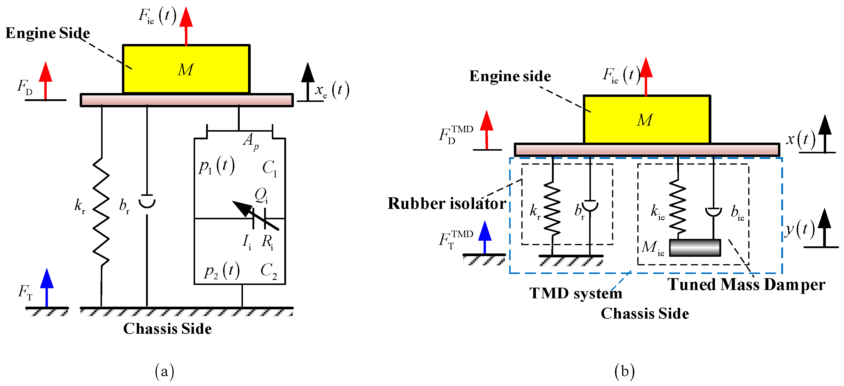
2. Linear LPM of the HEM

To better understand the dynamic performance of an HEM with an inertia track, the nonlinear characteristics are initially ignored and the linear time-invariant (LTI) lumped parameter model (LPM) [2,5,7,12] is used, as shown in Figure 2a. This model has been validated and is frequently used to express the performance of an HEM, which supports an engine with mass M. The continuum equations in the upper and lower chambers and fluid dynamic equations about the inertia track are as follows:
C 1 p ˙ 1 t + C 2 p ˙ 2 t = A p x ˙ e t ,
C 2 p ˙ 2 t = Q i t ,
p 1 t p 2 t = I i Q ˙ i t + R i Q i t ,
where p 1 t and p 2 t are the fluid pressure of the upper and lower chambers, respectively; C 1 and C 2 are the compliance in the upper and lower chambers, respectively; A p is the equivalent piston area of the main rubber; x e t is the displacement of the engine side; Q i t is the flow rate in the inertia track; and I i and R i are the inertia of the inertia track and the resistance in the inertia track, respectively.
The I i and R i can be computed as follows:
I i = ρ L i A i ,
where ρ is the fluid density; L i is the length of the inertia track; and A i is the cross-section area of inertia track.
R i = 128 μ L i π D h 4
where μ is the fluid kinematic viscosity, and D h is the hydraulic diameter of the inertia track and can be computed as follows:
D h = 4 A i P ,
where P is the wetted perimeter of the inertia track.
The driving point force at the engine side can be obtained as follows:
F D t = k r x e t + b r x ˙ e t + A p p 1 t ,
where k r and b r are the stiffness and damping of the main rubber, respectively.
F T t is the force transferred at the chassis side.
F T t = k r x e t + b r x ˙ e t + A p p 1 t
Transferring Equations (1)–(3) into the Laplace domain, the driving point force on the engine side can be obtained as follows:
F D s = k r X e s + b r s X e s + A p X e s C 1 A p X e s C 1 2 I i s 2 + R i s + K u + K l ,
where K u = 1 / C 1 is the bulk stiffness of the upper chamber, and K l = 1 / C 2 is the bulk stiffness of the lower chamber.
Similarly, the Laplace domain solution for the force transferred to the body side F T s can be obtained as follows:
F T s = k r X e s + b r s X e s + A p X e s C 1 A p X e s C 1 2 I i s 2 + R i s + K u + K l .
The transfer dynamic stiffness k T s and drive point dynamic stiffness k D s are defined as follows:
k T s = F T s X e s = k r + b r s + A p 2 C 1 1 1 C 1 1 I i s 2 + R i s + K u + K l ,
k D s = F D s X e s = k r + b r s + A p 2 C 1 1 1 C 1 1 I i s 2 + R i s + K u + K l .
Consider a TMD system supporting an engine (mass M), as shown in Figure 2b, where the TMD system consists of a rubber isolator with stiffness k r and damping b r and a TMD with equivalent mass M ie , equivalent stiffness k ie , and equivalent damping b ie .
Let
M ie = A p 2 I i ,   b ie = A p 2 R i ,   k ie = A p 2 / C 1 .
Considering the compliance C 2 of the lower chamber is too large to be considered, the drive point dynamic stiffness and transfer dynamic stiffness can be simplified as follows:
k D s = k r + b r s + k ie 1 k ie 1 M ie s + b ie s + k ie ,
k T s = k r + b r s + k ie 1 k ie 1 M ie s + b ie s + k ie .
The dynamic equations for the engine and TMD are
M x ¨ + k r x + b r x ˙ + k ie x y + b ie x ˙ y ˙ = F ie t ,
M ie y ¨ + k ie y x + b ie y ˙ x ˙ = 0 ,
where x and y are the displacement of the engine and the TMD, respectively. F ie t is the exciting force applied on the engine.
The force F D TMD ( t ) applied to the engine by the TMD system is
F D TMD t = k r x t + b r x ˙ t + k ie x t y t + b ie x ˙ t y ˙ t .
The force transferred to the chassis is
F T TMD t = k r x t + b r x ˙ t .
Transferring Equations (16)–(19) into the Laplace domain, the drive point dynamic stiffness of the TMD system is
k D TMD s = F D TMD s x s = k r + b r s + k ie 1 k ie 1 M ie s + b ie s + k ie .
The transfer dynamic stiffness of the TMD system is
k T TMD s = F T TMD s x s = k r + b r s .
Comparing Equation (20) with Equation (21), the drive point dynamic stiffness of the TMD system and the transfer dynamic stiffness of the TMD system are different.
The motion of the engine can also be described as follows:
x s = F ie s M s 2 + k D TMD s .
The drive point stiffness can be used to evaluate the movement of the engine, whereas the transfer dynamic stiffness can be used to evaluate the force transferred to the chassis.

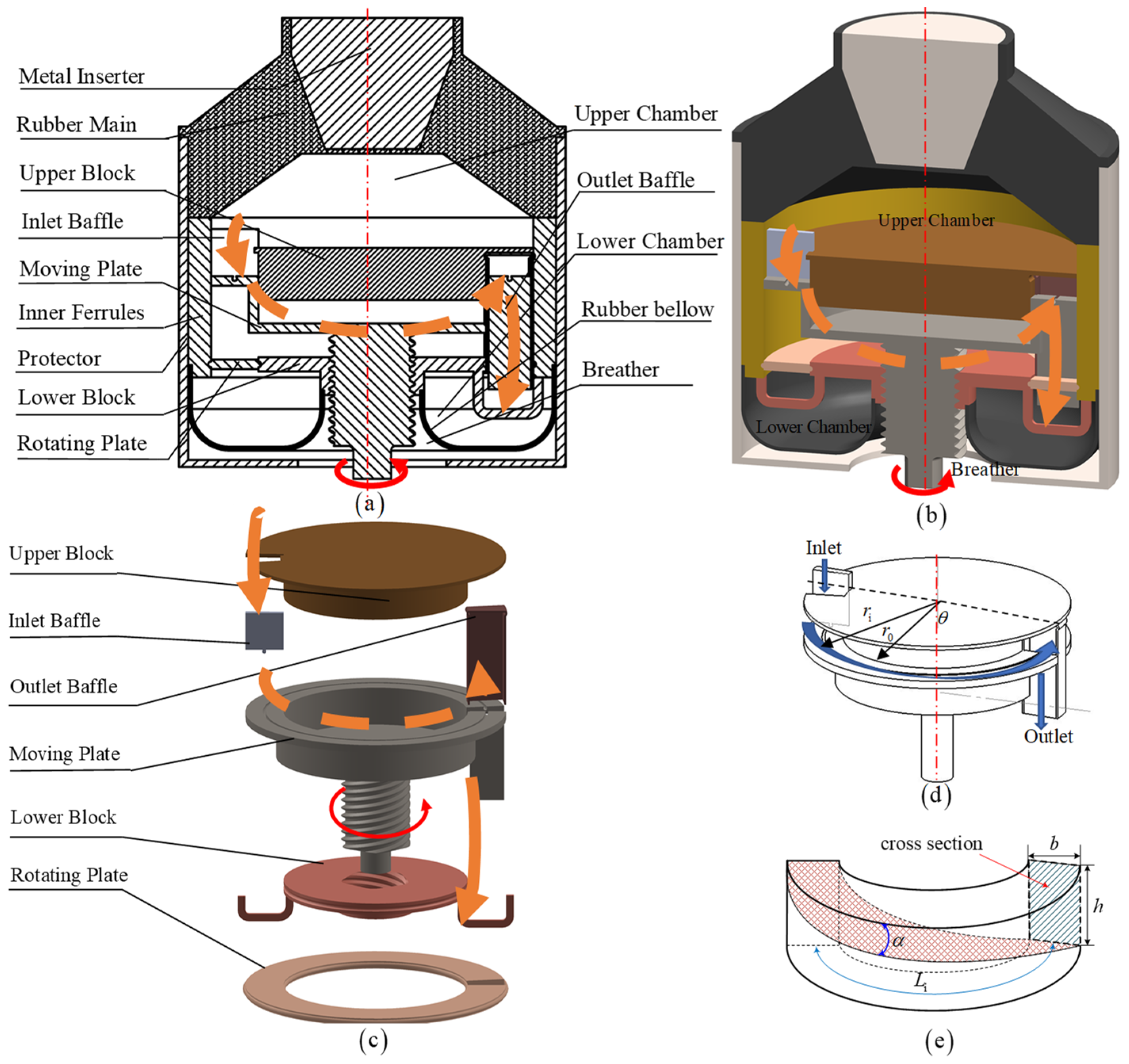
3. Design of a New Semiactive HEM Tuning Only the Damping without MR/ER Fluid

Although there are some differences between the HEM and TMD systems, the expression of the drive point stiffness k D TMD s for the TMD system is similar to the drive point stiffness k D s and transfer dynamic stiffness k T s for the HEM. Experts can consider the key frequency points of the dynamic stiffness spectrum, such as the notch frequency, and experts can also refer to the design experience of the TMD system. The equivalent parameters k r , b r , M ie , b ie , and k ie of the TMD system are derived by the changeable lumped parameters ( k r , b r , A p , L i , A i , P , μ , and C 1 ) and the invariable parameter fluid density ρ of the HEM:
k r | TMD = k r | HEM ,
b r | TMD = b r | HEM ,
M ie | TMD = ρ A p 2 L i A i | HEM ,
b ie | TMD = A p 2 μ L i A i 4 P 4 | HEM ,
k ie | TMD = A p 2 1 C 1 | HEM .
From Equations (23)–(27), tuning one parameter of the HEM may change more than one parameter of the TMD, changing one parameter of the TMD may occur by tuning more than one parameter of the HEM. From the viewpoint of the TMD, the clear goal is to adjust each parameter with a proper value when designing a passive HEM. However, with the semiactive HEM, it is also not difficult to determine which parameter or parameters are adjusted. For example, Foumani [12] tunes only k r with the aid of shape memory alloys; Truong [14] tunes both M ie and b ie by tuning the area of the inertia track; Wang [2] tunes both M ie and b ie by tuning both the inertia track length L i and the cross-section area A i ; Arzanpour [17] tunes b ie with the aid of ER fluid; Mansour [19] tunes b ie with the aid of MR fluid, etc.
To tune only the b ie of the TMD system like an MR/ER semiactive HEM, this paper proposes a new semiactive HEM by tuning both the cross-section area A i and the inertia track length L i simultaneously with the aid of a screw thread between the moving plate and the lower block. This newly designed semiactive HEM can continuously adjust the damping of the inertia track without other lumped parameters. It can function like an MR/ER HEM but is less expensive and has a wider adjustability range.
The detail of the proposed semiactive HEM in a 2D cutaway view is shown in Figure 3a, and a 3D cutaway view is shown in Figure 3b. When assembling it, the metal inserter, rubber main, and inner ferrule are bonded together. Secondly, the inertia track comprises an upper block, an inlet baffle, a moving plate, a lower block, an outlet baffle, and a rotating plate. From Figure 3c, there is a threaded connection between the lower block and the moving plate, allowing the moving plate to rotate and move in an axial direction relative to the lower block, enabling control of both the length and cross-sectional area of the inertia track simultaneously. The upper and lower blocks are fixed to the inner ferrule. The rotating plate is embedded between the inner ferrule and the lower block through a slide groove to ensure the synchronized rotation of the rotating plate and the outlet baffle. A fluid medium is injected, and the rubber below is used to seal the fluid. A protector is fixed to protect the inner components. The engine connects with the mount through a metal inserter, a protector is used to connect the chassis, and then this HEM can function as a vibration isolator. Figure 3d shows the location of the outlet on the lower block at the right of the block. When the fluid in the upper chamber flows into the lower chamber, the flow direction in the inertia track is counterclockwise.
(1)
Relationship between the cross-section area and the length of the inertia track
Because the inertia track length L i and cross-section area A i influence both M ie and b ie , but we want to make M ie uncontrolled, we should make L i / A i = constant from Equation (25). In other words, the cross-section area of the inertia track is zero when the length of that is zero. When the length of the newly designed inertia track decreases, the cross-section area decreases and, conversely, increases, as shown in Figure 3e.
(2)
Assembly requirement
Workers should pay attention to the assembly of both the inlet baffle and the outlet baffle. The moving plate rotates around the central axis due to the driving mechanism and translates along the same axis simultaneously. The inlet baffle achieves relative rotational motion by cooperating with the groove on the moving plate and axial relative translation by cooperating with the slot on the upper block, as depicted in Figure 3c. The outlet baffle realizes the axial relative translation by cooperating with the slot in the moving plate and rotates relative to the lower block by cooperating with the slot of the rotating plate.
(3)
Control the inertia area
When continuous control over the cross-sectional area and length of the inertial track is necessary, an external motor is required to drive the screw located at the bottom of the moving plate in Figure 3c.

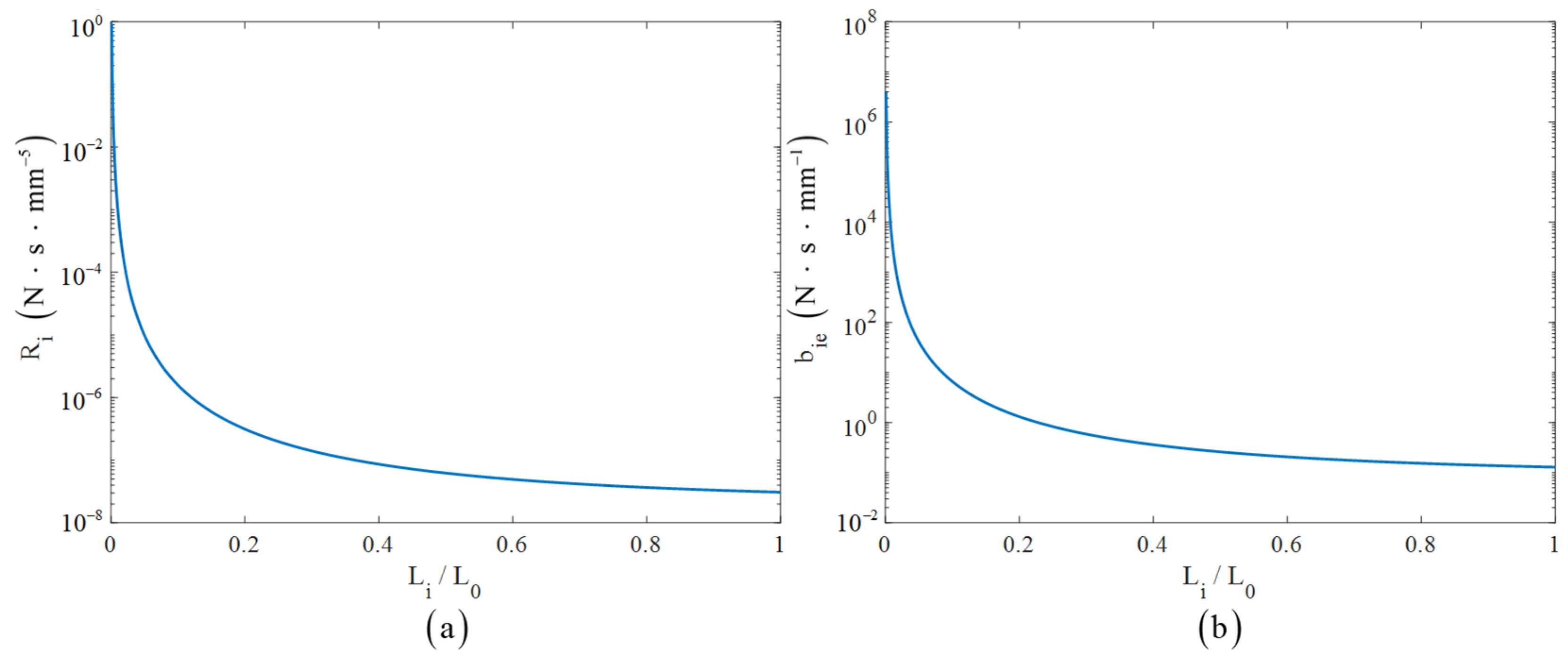
4. Dynamic Performance of the New Semiactive HEM

4.1. Lumped Parameters

The semiactive HEM would tune only the lumped damping of the inertia track R i or the equivalent damping b ie without the other parameters of the TMD system.
Let radius r i of the inertia track’s neutral line and the rotation angle θ of the moving plate screw be as shown in Figure 3d. The length of the inertia track is L i :
L i = π r i θ .
Equation (28) becomes
θ = L i / r i π .
The height and cross-section area of the inertia track are
h L i = L i tan   α = π r i θ tan   α ,
A L i = b L i tan   α = π b r i θ tan   α ,
where α is the spiral lift angle of the moving plate, and b is the width of the inertia track.
The inertia parameters of the inertia track are
I i L i = ρ L i / A i L i = ρ / b tan   α ,
M ie L i = A p 2 I i L i = ρ A p 2 / b tan   α .
Since ρ , b , and tan α are invariant, considering Equations (32) and (13), the inertia of the inertia track I i L i and M ie do not change with L i .
The wetted perimeter of the inertia track is
P L i = 2 h L i + b = 2 L i tan   α + 2 b = 2 π r i θ tan   α + 2 b .
R i L i and b ie L i are
R i L i = 128 μ L / π 2 b L i tan   α L i tan   α + b 4 = 128 μ / π L i 3 2 b tan   α L i tan   α + b 4 ,
b ie L i = A p 2 R i L i = 128 μ A p 2 / π L i 3 2 b tan   α L i tan   α + b 4 .
When L i = 0 , we have
R i L i = 0 = +
b ie L i = 0 = +
Let R 1 = R i L 0 , b 1 = b ie L 0 , and Equations (37) and (38) indicate the tunable range of lumped damping and equivalent damping R i     [ R 1 , + ) , b ie     [ b 1 , + ) . Because the damping of the anti-freeze liquid is weaker than that of the MR/ER fluid with the same geometry, the lower limit of the damping of the newly designed HEM is smaller than that of MR/ER fluid. Because the tunable damping of the MR/ER fluid-based semiactive mount is proportional to the magnetic/electric field intensity, which cannot be + , the upper bound is finite. However, the upper bound of the damping of the newly designed HEM is + . In other words, the damping of the newly designed HEM has a much wider tunable range than that of the MR/ER fluid-based semiactive mount.
According to Foumani [12], the upper compliance C 1 can be calculated as follows:
C 1 = Δ V 1 Δ P 1 ,
where the change in the upper chamber, denoted by Δ V 1 , is a result of the variation in pressure, represented by Δ P 1 .
By closing the inertial track in the hydraulic mount finite element model and applying pressure to the top of the upper chamber, we can calculate the volume change Δ V 1 and the pressure change Δ P 1 to determine the compliance of the upper chamber C 1 . The compliance in the lower chamber C 2 can also be computed.
Using the parameters in Table 1, the damping R i L i and b ie L i become smaller when the length of the inertia track becomes larger, as shown in Figure 4. This shows that the new semiactive HEM can utilize the change in the geometry of the inertia track to tune the damping of the inertia track instead of the expensive MR/ER fluid.
Figure 5 shows the dynamic stiffness (absolute value) spectrum with different lengths of inertia track, and there is a fixed frequency point P 1 , which the dynamic stiffness curve with different inertia track lengths will move through. When the inertia track length increases, the lowest value of the dynamic stiffness spectrum decreases and the peak value of the dynamic stiffness curves increases.

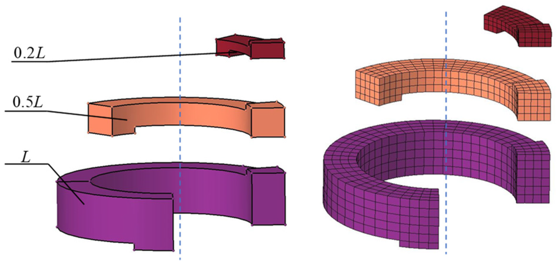
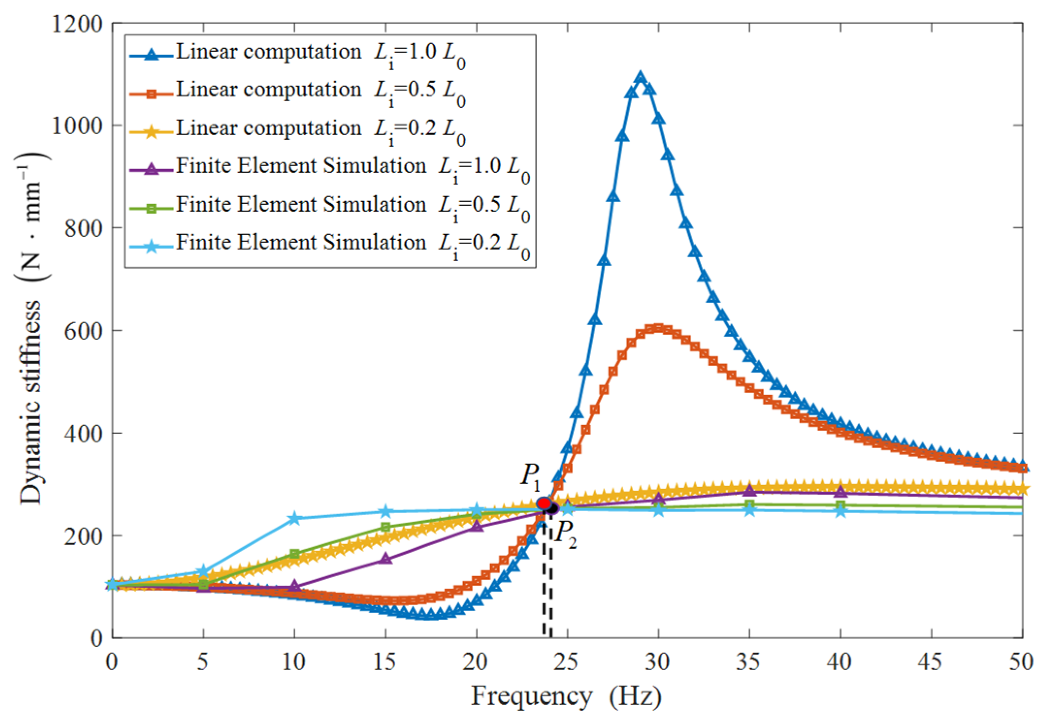
4.2. Simulation Validation Using the Finite Element Method

There is a fluid–structure interaction for the HEM. To compare and verify the theoretical linear analysis scheme of the new semiactive HEM, three finite element models using the parameters in Table 1 are established to analyze the dynamic stiffness spectrum of the HEM. Three models of the inertia track with three geometry parameters are shown in Figure 6.
The metal inserts are subjected to a series of sine wave excitations, each with an amplitude of 1 mm and a frequency ranging from 0 to 100 Hz. Force–displacement curves at each excitation frequency are calculated for each finite element model with specified inertia track lengths, and force–displacement curves at some typical frequencies are shown in Figure 7. From each hysteresis loop, the dynamic stiffness of the HEM at a certain frequency point can be calculated. The dynamic stiffness spectrum was calculated when the inertia track length L i is equal to 1.0   L 0 , 0.5   L 0 , and 0.2   L 0 , respectively. The results shown in Figure 8 reveal that when the excitation frequency is less than the fixed frequency point P 2 , the dynamic stiffness from the simulation model decreases as the length of the inertia track increases; when the excitation frequency is greater than the fixed frequency point P 2 , the dynamic stiffness from the simulation model increases as the length of the inertia track increases. The fixed point P 1 of the linear model and the fixed point P 2 of the simulation model are close to each other. The overall trend is consistent with the results of the linear model, but there is still a discrepancy between the peak and valley dynamic stiffnesses.

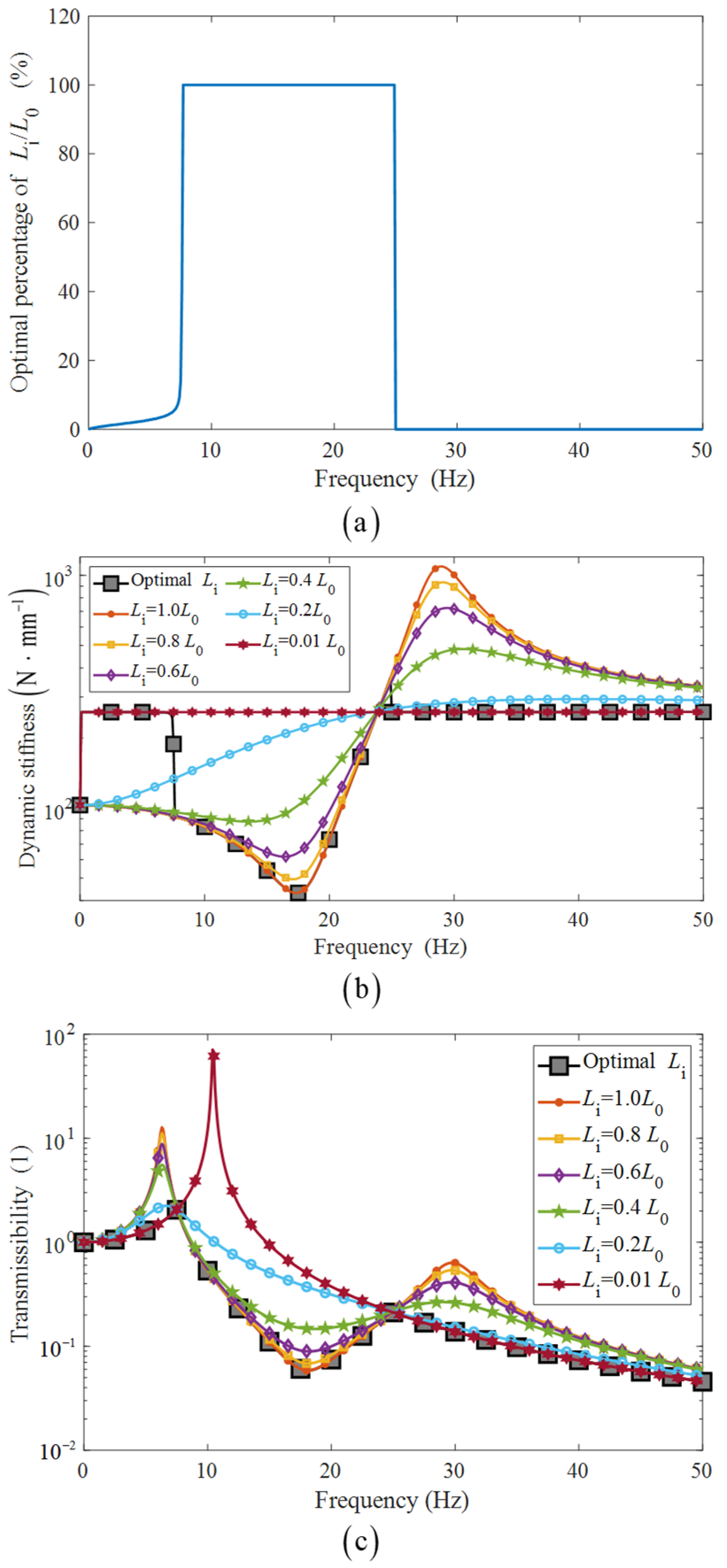
4.3. Vibration Isolation Performance of the Newly Designed HEM

Once the change in the length of the inertia track is found, Equation (29) can be used to determine the rotation angle of the moving plate screw. The damping of the inertia track depends on the length of the inertia track. The shorter the length is, the larger the damping is. Consider an engine supported by the proposed HEM, as shown in Figure 2a, the optimal length of inertia track should minimize the transmissibility T f L i , ω :
T f L i , ω = k T ( j ω ) M ω 2 + k T L i ,   j ω
The optimal length of the inertia track is shown in Figure 9a, the optimal dynamic stiffness of the new semiactive HEM is shown in Figure 9b, and optimal transmissibility is shown in Figure 9c. At the middle-frequency band, the length of the inertia track is the largest, and this indicates the weak damping of the inertia track is preferred. The inertia track is almost closed at lower and higher frequency bands to provide large damping and thus improve the vibration isolation performance. Generally, from the optimal length of the inertia track in Figure 9a, experts may choose an on–off strategy to control the damping, which means switching between the weakest and largest damping, for better vibration isolation performance. By the way, for a passive HEM whose parameters are not changeable, there must be a compromise proper design of the inertia track for wide-band vibration isolation performance, so experts can use the new proposed design to determine the proper geometry parameters when designing an HEM.

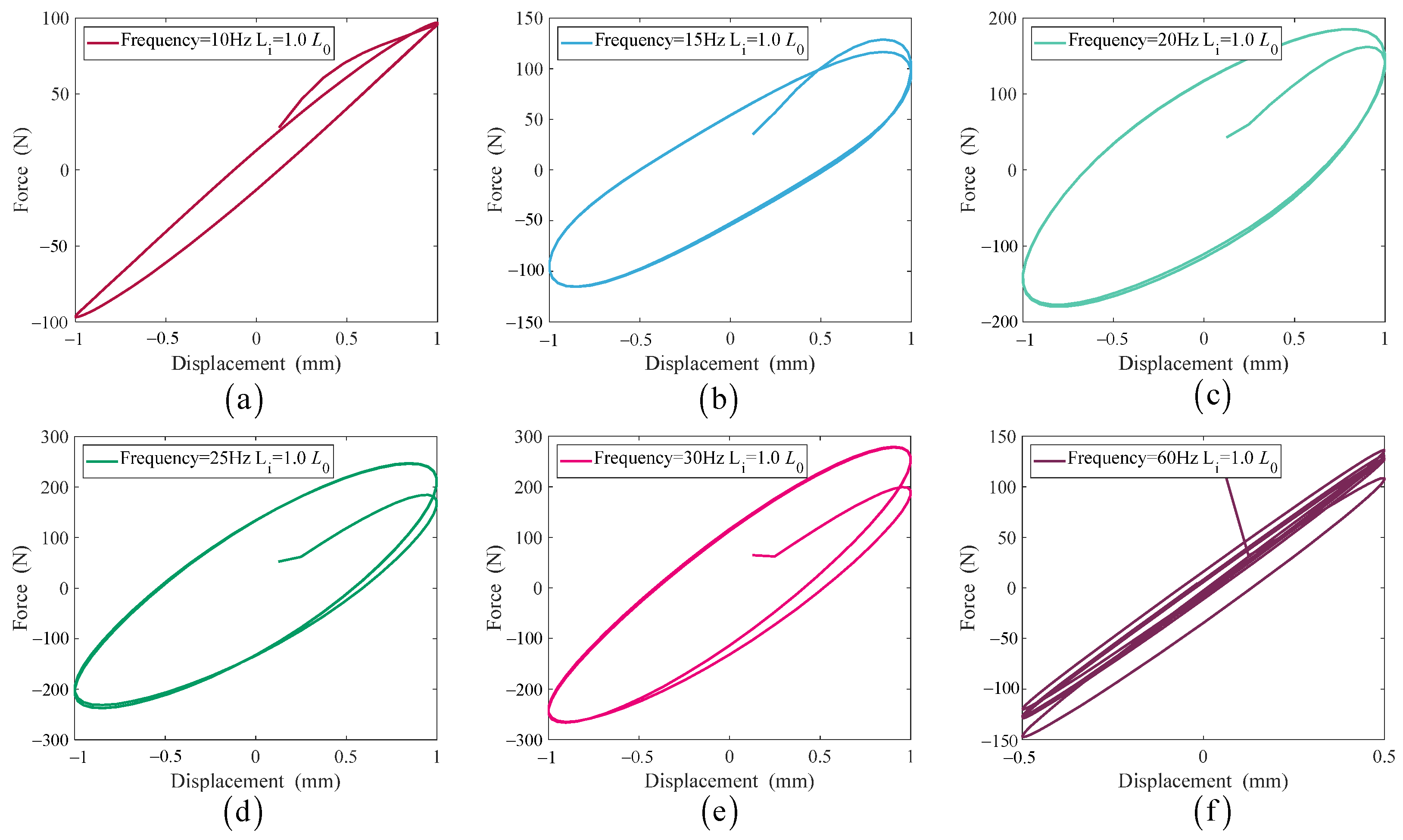
5. Nonlinear Modeling and Dynamic Stiffness Comparison of the Newly Designed HEM and MRF Mount

Although the theoretical performance of the HEM can be clearly understood based on the linear model shown in Figure 2a, the simulation results in Figure 8 demonstrate that nonlinear factors affect the dynamic stiffness. Therefore, it is necessary to establish a nonlinear model of the newly designed HEM in this work and evaluate its dynamic performance. Additionally, we aim to compare its nonlinear dynamic performance with that of MR/ER fluid-based semiactive HEMs. While there are various nonlinear factors involved, such as carbon-filled rubber, this paper only considers the turbulence-induced nonlinear damping while ignoring other nonlinear factors.
Liquid flowing through the inertia track will produce energy losses for various reasons, and the energy losses are manifested as intuitive pressure losses. The R i in Equation (3) describes the pressure loss due to the inertia damping.
The energy loss along the inertia track caused by the equivalent linear fluid resistance R i is described as follows [14]:
Δ P I = R i Q i = 128 μ L i π D h 4 Q i .
The local energy loss due to the sudden change in the cross-section of fluid flowing through the inlet and outlet can be expressed as follows [26]:
Δ P d = 1 2 ρ ζ d 1 + ζ d 2 Q i A i Q i A i ,
where ζ d 1 and ζ d 2 are the local factor for the sudden contraction and expansion of the cross-section, respectively.
According to the literature [27], the pressure loss due to the bending effect caused by the fluid flowing along the curved inertia track can be expressed as
Δ P b = 1 2 ρ ζ b Q i A i Q i A i ,
where the empirical formula for the bending effect resistance factor ζ b is
ζ b = 0.131 + 1.847 D h r i 3.5 θ 90 .
As shown in Figure 3d, r i is the radius of curvature of the centerline of the inertia track, and θ is the rotation angle of the inertia track.
Considering the pressure loss due to the various reasons mentioned above, compared to Equation (3), the pressure change equation can be expressed as
p 1 t p 2 t = I i Q ˙ i t + R i + 1 2 ρ ζ d + ζ b Q i A i 2 Q i t = I i Q ˙ i t + R in   Q i t ,
where
R in = R i + 1 2 ρ ζ d + ζ b   Q i A i 2 .
The nonlinear dynamic model of an HEM can be defined by Equations (1), (2), (8), (45) and (46). Considering the existence of nonlinear terms in the system of equations, MATLAB was used to determine the solution. The dynamic stiffness of the dynamic characters in the frequency domain can be obtained by determining the relevant parameter values, selecting a suitable integration method, and giving the proper amplitude and frequency of the excitation signal.

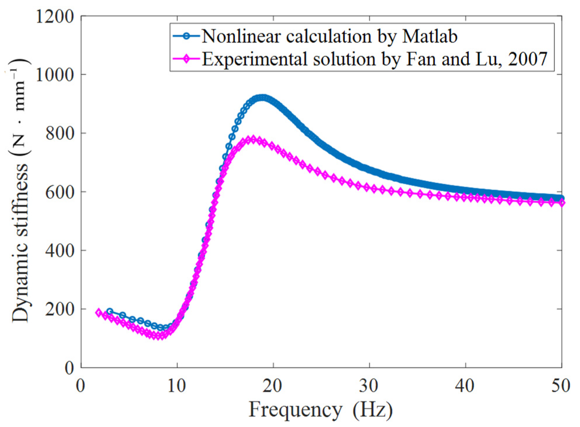
5.1. Parameter Selection and Verification of the MATLAB Solution Procedure

According to Fan and Lu [26], the selected damping parameters ζ d 1 = 0.5 , ζ d 2 = 1.0 , and θ = 270 . To verify the accuracy of the nonlinear solution procedure for HEMs, the dynamic stiffness characteristics in the frequency domain are calculated with the set of lumped parameters in Table 1 from the literature [26]. Here, the ode4 algorithm is used for the MATLAB program with time step 0.001 s.
The comparison of the numerical results and experimental results (Fan and Lu [26]) of the dynamic stiffness spectrum is shown in Figure 10. Although there are some differences, the trend of the dynamic stiffness spectrum is consistent with that of the result in the literature [26], and the subsequent analysis used the MATLAB program.
The parameters in Table 2 are used to calculate the nonlinear response of the newly designed HEM. Both rotation angles θ and L i of the newly designed HEM are tunable.
The dynamic stiffness spectrums for different lengths of inertia track based on a nonlinear model and a linear model are shown in Figure 11. According to Equations (30)–(36), the lumped parameters L i and A i change with the rotation angle θ of the moving plate screw of the newly designed HEM, but it is ensured that only b ie R i is adjustable, and the other equivalent parameters in the TMD system are unaltered. Comparing Equation (46) and Equation (5), the nonlinear model considers more nonlinear damping of the inertia track than the linear model. Therefore, the damping of the inertia track in the nonlinear model is larger than that in the linear model for the same length of inertia track. From Figure 11, it can be seen that the dynamic stiffness spectrum from the nonlinear model follows the same tendency as that from the linear model for larger damping (smaller inertia track length). The fixed point P 1 of the linear model and the fixed point P 3 of the nonlinear model are close to each other.

5.2. Comparison with the MR Fluid HEM

Because the MR/ER-based semiactive mount would tune the damping, we take the MR-based mount as an example to show the advantages of the newly designed HEM over an MR/ER-based mount. An MR-based HEM can be obtained by adopting the MRF as a fluid medium inside a common passive HEM and by placing a coil holder with a uniformly wound copper wire coil around the inertia track. The magnetic field generated by the energized coil changes the flow characteristics (viscosity) of the MR fluid and thus changes the dynamic performance of the HEM. We compare the dynamic performance of a typical MR mount in the literature [28] to the performance of the newly designed HEM.
The pressure difference between the upper chamber pressure p 1 t and the lower chamber pressure p 2 t of an MRF mount [29] is
p 1 t p 2 t = Δ P I + Δ P μ + Δ P τ ,
where Δ P I is the pressure drop due to the inertia of the fluid flow; Δ P μ is the pressure drop caused by the fluid viscosity and the pressure drop caused by the energy loss when the fluid flows through the inertia track; and Δ P τ is the pressure drop due to the yield stress of the fluid.
According to Equations (41)–(46), Δ P I and Δ P μ are
Δ P I = I im Q ˙ im t Δ P μ = 128 μ m L im π D hm 4 Q im + 1 2 ρ m ζ lm + ζ dm + ζ bm   Q im A im 2   Q im .
According to the literature [29], Δ P τ can be obtained as follows:
Δ P τ = c τ L im k τ g 1 Q im   Q im ,
where the coefficient c = 2.07 3.07 depends on the flow velocity profile [30], for convenience, c = 2.57 ; k τ is the ratio of effective area caused by magnetic field; g is the gap of MRF; the parameters I im , Q im , μ m , L im , D hm , ζ lm , ζ dm , ζ bm , and A im have the same physical meanings as parameters such as I i without the subscript m , and the parameters with subscript m are the parameters of the MR mount; and the yield shear stress τ [28] is
τ = C τ   ·   2.717 × 10 5 · Φ 1.5239 · tanh   6.33 × 10 6 · H m ,
where H m is the magnetic field intensity, the tunable range is H m = 0 200   A / mm ; the constant C τ depends on the carrier oil type, C τ = 1.16 ; and Φ is the iron volume fraction, Φ = 0.22 .
Equation (47) can be rewritten as follows:
p 1 t p 2 t = I im Q ˙ im t + R im Q im t ,
where the equivalent viscous resistance coefficient of MRF flow R i m is
R im = 128 μ m L im π D hm 4 + 1 2 ρ m ζ lm + ζ dm + ζ bm Q im A im 2 + c τ L im k τ g 1 Q im .
To better compare the performances of our newly designed HEM and MRF mount, the MRF HEM adopts the same parameter value set of the newly designed HEM, except for the field shear stress τ -related parameters. Table 2 lists the values of all the key parameters of the MRF mount.
Table 2. Detailed parameters of the MRF mount.
ParametersValuesUnits
M 60 kg
k rm 102.9 N · mm 1
b rm 0.045 N · s · mm 1
A pm 2047.8 mm 2
C 1 m 2.699 × 10 4 mm 5 · N 1
C 2 m 8.084 × 10 6 mm 5 · N 1
L 0 m 138.95 mm
A im 139.4 mm 2
ρ m 1.15 × 10 6 kg · mm 3
μ m 1.0 × 10 7 N · s · mm 2
b m 10 mm
c 2.57 N / A
g 11.6 mm
k τ 0.58 N / A
H m 0 , 200 A / mm
Δ P τ in Equation (47) is added to the nonlinear model in Section 5.1 to determine the dynamic stiffness of the MRF mount when the magnetic field intensity H m is in the range of 0 to 200 A / mm .
The results in Figure 12 show that if the magnetic field intensity is less than 20   A / mm , when the excitation frequency is less than the fixed-point P 4 frequency, the dynamic stiffness increases with the increase in the magnetic intensity, while the dynamic stiffness decreases with the increase in the magnetic intensity when the excitation frequency is greater than the fixed-point P 4 frequency; when magnetic field intensity is greater than 20   A / mm , the dynamic stiffness is affected slightly by the magnetic intensity. The change in the dynamic stiffness with a magnetic intensity greater than 20   A / mm means that the MR fluid flow in the track is impeded as the viscosity increases due to the increasing magnetic intensity, and this change is the same as the results in Ref. [31]. The dynamic stiffness of the newly designed HEM with inertia track length L i = 1.0   L 0 is the same as that of the MRF mount at magnetic field strength H m = 0   A / mm . The dynamic stiffness of the newly designed HEM with an inertia track length less than 0.1   L 0 is the same as that of the MRF mount at magnetic field intensity H m greater than 20   A / mm . In all, the newly designed HEM has a similar dynamic stiffness control effect to that of the MRF mount. On the other hand, the newly designed HEM does not require expensive MR/ER fluid or additional continuous external energy to maintain the magnetic intensity.
The fluid properties for various MR fluids, distinct from those reported in the literature, are presented in Table 3. The fluids from Rang-Lin Fan [32] and Thanh Quoc Truong [14] have a lower fluid kinematic viscosity than the MRF in Quoc NV [33]. As shown in Figure 13, for the newly designed HEM with low-viscosity fluid, when the excitation frequency is less than the fixed-point P 5 frequency, the lower control bound of the dynamic stiffness is lower; while the upper control bound of the dynamic stiffness is higher when the excitation frequency is greater than the fixed-point frequency. The overall dynamic stiffness control range for the newly designed HEM is wider than that of the MRF mount. The dynamic stiffness tunable range of both the newly designed HEM and MRF mount decreases as the viscosity of the fluid increases.

6. Conclusions

In this paper, a newly designed HEM is proposed that allows continuously controlled lumped damping over a wide range and provides better vibration isolation performance than an MRF mount. The newly designed HEM only adjusted the damping in the LPM rather than other parameters by controlling the inertia track area and length simultaneously by rotating the moving plate in the inertia channel. The dynamic performance and vibration isolation performance of the newly designed HEM are determined using the linear LPM with adjustable damping in the range of [R1, +∞], and the optimal length control strategy for the inertia channel and the corresponding dynamic stiffness and transfer rate are derived based on the force transmissibility equation. In order to compare the damping and vibration isolation performances with those of the MRF mounts, the nonlinear LPMs of the new HEM and typical MRF mount are established. The accuracy of the nonlinear LPM analysis procedures is ensured by comparing the results with the existing literature.
The results show that the newly designed HEM mainly presents the following advantages: (1) The actuator that controls the dynamic stiffness is an inexpensive threaded moving plate rather than expensive MR/ER fluid and requires no continuous external energy input to control the dynamic stiffness. (2) The newly designed HEM is extremely light and easy to assemble since no other circuitry exists to generate magnetic or electric fields to change the behavior of the MR/ER fluid. (3) With the same parameters, the newly designed HEM can achieve the same dynamic stiffness control as the MRF mount, and the newly designed HEM has a wider dynamic stiffness control range with inexpensive low-viscosity hydraulic fluids.

Author Contributions

Conceptualization, M.W. and Y.-C.Z.; methodology, Y.-C.Z., K.-Y.G. and P.-L.Z.; software, H.Y.; validation, Y.-C.Z.; formal analysis, Y.-C.Z.; investigation, M.W.; resources, G.-F.Y.; writing—original draft preparation, Y.-C.Z.; writing—review and editing, G.-F.Y., M.W., H.Y., K.-Y.G. and P.-L.Z.; visualization, H.Y.; supervision, G.-F.Y.; project administration, G.-F.Y.; funding acquisition, G.-F.Y. All authors have read and agreed to the published version of the manuscript.

Funding

This research received no external funding.

Institutional Review Board Statement

Not applicable.

Informed Consent Statement

Not applicable.

Data Availability Statement

The data are available from the author on request.

Acknowledgments

The authors thank China FAW Group Corporation for supporting this study. Thanks are also due to Project 985-Automotive Engineering of Jilin University.

Conflicts of Interest

The authors declare no conflict of interest.

Nomenclature

A p equivalent piston area of main rubber ( mm 2 )
A i cross-sectional area of inertia track ( mm 2 )
b width of the inertia track ( mm )
b r damping of the main rubber ( N   ·   s   ·   mm 1 )
b ie equivalent damping of TMD ( N   ·   s   ·   mm 1 )
c coefficient that depends on the flow velocity profile
C 1 compliance in the upper chamber ( mm 5   ·   N 1 )
C 2 compliance in the lower chamber ( mm 5   ·   N 1 )
C c o n equivalent parameter of TMD
C τ constant depending on the carrier oil type
D h hydraulic diameter of the inertia track ( mm 5   ·   N 1 )
F D t , F D s driving point force on the engine side ( N )
F T t   F T s force transmitted to the body side ( N )
F T TMD t force transferred to the body side by the rubber isolator with TMD ( N )
F D TMD ( t ) force applied to the engine by the rubber isolator with TMD ( N )
F ie t force applied to the engine ( N )
g gap of MRF ( mm )
H m magnetic field intensity ( A   ·   mm 1 )
I i inertia of the inertia track ( N   ·   s   ·   m 5 )
k D s drive point dynamic stiffness ( N   ·   mm 1 )
k D TMD s drive point dynamic stiffness of the rubber isolator with TMD ( N   ·   mm 1 )
k ie equivalent stiffness of TMD ( N   ·   mm 1 )
k T s transfer dynamic stiffness ( N   ·   mm 1 )
k T TMD s transfer dynamic stiffness of the rubber isolator with TMD ( N   ·   mm 1 )
K l bulk stiffness of lower chamber ( N   ·   mm 5 )
k r stiffness of the main rubber ( N   ·   mm 1 )
K u bulk stiffness of upper chamber ( N   ·   mm 5 )
k τ effective area ratio due to magnetic field
L i length of inertia track ( mm )
M mass at engine side ( kg )
M ie equivalent mass of TMD ( kg )
P wetted perimeter of the inertia track ( mm )
p 1 t pressure of upper fluid chamber ( Pa )
p 2 t pressure of lower fluid chamber ( Pa )
p a r a equivalent parameter of TMD
Q i t flow rate of the inertia track ( mm 3   ·   s )
r i radius of the inertia track’s neutral line ( mm )
R i resistance in the inertia track ( N   ·   s   ·   mm 5 )
R in resistance in the inertia track of the nonlinear LPM ( N   ·   s   ·   mm 5 )
  s Laplace operator
T f L i , ω transmissibility
tanh hyperbolic tangent function
x , x s displacement of the engine side of the rubber isolator with TMD ( mm )
x e t , X e s displacement of the engine side ( mm )
y displacement of the TMD mass side ( mm )
P i   i = 1 5 fixed point on frequency–dynamic stiffness
Δ P l energy loss along the inertia track caused by the viscosity of the liquid ( Pa )
Δ P d local energy loss due to the sudden change in the cross-section of the fluid flowing through the inlet and outlet ( Pa )
Δ P I pressure drop generated by inertia of fluid flow ( Pa )
Δ P μ pressure drop caused by the viscosity of the fluid and the pressure drop caused by energy loss due to various reasons when the fluid flows through the inertia tracks ( Pa )
Δ P τ pressure drop due to the yield stress of fluid ( Pa )
α spiral lift angle of the moving plate
α e , β e , , γ e index parameters
μ fluid kinematic viscosity ( N   ·   s   ·   mm 2 )
ρ fluid density ( kg   ·   mm 3 )
θ rotation angle of the moving plate
ζ b empirical formula for the bending effect resistance factor
ζ d 1 local factor for the sudden contraction of the cross-section
ζ d 2 local factor for the sudden expansion of the cross-section
Φ iron volume fraction
HEMhydraulic engine mount
LPM lumped parameter model
MR magneto-rheological
ER electric-rheological
subscript m parameters with subscript m are the parameters of the MRF mount

References

  1. Yu, Y.H.; Naganathan, N.G.; Dukkipati, R.V. A literature review of automotive vehicle engine mounting systems. Mech. Mach. Theory 2001, 36, 123–142. [Google Scholar] [CrossRef]
  2. Wang, M.; Yao, G.F.; Zhao, J.Z.; Qin, M. A novel design of semi-active hydraulic mount with wide-band tunable notch frequency. J. Sound Vib. 2014, 333, 2196–2211. [Google Scholar] [CrossRef]
  3. Hu, J.; Zhu, D.; Chen, J.; Li, W. Refined response axis decoupling axiom for a coupled vibrating system with spectrally-varying mount properties. J. Vib. Control 2017, 24, 3233–3248. [Google Scholar] [CrossRef]
  4. Qin, W.; Shangguan, W.-B.; Luo, G.; Xie, Z. A method for estimating mount isolations of powertrain mounting systems. J. Sound Vib. 2018, 426, 278–295. [Google Scholar] [CrossRef]
  5. Singh, R.; Kim, G.; Ravindra, P.V. Linear analysis of automotive hydro-mechanical mount with emphasis on decoupler characteristics. J. Sound Vib. 1992, 158, 219–243. [Google Scholar] [CrossRef]
  6. Kim, G.; Singh, R. A study of passive and adaptive hydraulic engine mount systems with emphasis on non-linear characteristics. J. Sound Vib. 1995, 179, 427–453. [Google Scholar] [CrossRef]
  7. Jazar, G.N.; Golnaraghi, M.F. Nonlinear modeling, experimental verification, and theoretical analysis of a hydraulic engine mount. J. Vib. Control 2002, 8, 87–116. [Google Scholar] [CrossRef]
  8. Shangguan, W.B.; Lu, Z.H. Experimental study and simulation of a hydraulic engine mount with fully coupled fluid–structure interaction finite element analysis model. Comput. Struct. 2004, 82, 1751–1771. [Google Scholar] [CrossRef]
  9. Stosiak, M.; Karpenko, M.; Prentkovskis, O.; Deptuła, A.; Skačkauskas, P. Research of vibrations effect on hydraulic valves in military vehicles. Def. Technol. 2023. [Google Scholar] [CrossRef]
  10. Liang, T.Y.; Liang, T.Y.; Shi, W.K. Study on electromagnetic actuator active engine mount with fuzzy control. In Proceedings of the 2009 IEEE International Conference on Mechatronics and Automation, Changchun, China, 9–12 August 2009; Volume 1–7, pp. 3010–3014. [Google Scholar] [CrossRef]
  11. Mansour, H.; Arzanpour, S.; Golnaraghi, F. Design of a solenoid valve based active engine mount. J. Vib. Control 2011, 18, 1221–1232. [Google Scholar] [CrossRef]
  12. Foumani, M.S.; Khajepour, A.; Durali, M. Application of Shape Memory Alloys to a New Adaptive Hydraulic Mount. In International Body Engineering Conference & Exhibition and Automotive & Transportation Technology Congress; SAE Technical Paper; SAE: Warrendale, PA, USA, 2002. [Google Scholar] [CrossRef]
  13. Foumani, M.S.; Khajepour, A.; Durali, M. A new high-performance adaptive engine mount. J. Vib. Control 2004, 10, 39–54. [Google Scholar] [CrossRef]
  14. Truong, T.Q.; Ahn, K.K. A new type of semi-active hydraulic engine mount using controllable area of inertia track. J. Sound Vib. 2010, 329, 247–260. [Google Scholar] [CrossRef]
  15. Vahdati, N.; Heidari, S. A novel semi-active fluid mount using a multi-layer piezoelectric beam. J. Vib. Control 2010, 16, 2215–2234. [Google Scholar] [CrossRef]
  16. Elahinia, M.; Ciocanel, C.; Nguyen, T.M.; Wang, S. Mr- and er-based semiactive engine mounts: A review. Smart Mater. Res. 2013, 2013, 831017. [Google Scholar] [CrossRef]
  17. Arzanpour, S.; Golnaraghi, M.F. A novel semi-active magnetorheological bushing design for variable displacement engines. J. Intell. Mater. Syst. Struct. 2008, 19, 989–1003. [Google Scholar] [CrossRef]
  18. Tikani, R.; Vahdati, N.; Ziaei-Rad, S. Two-mode operation engine mount design for automotive applications. Shock Vib. 2012, 19, 1267–1280. [Google Scholar] [CrossRef]
  19. Mansour, H.; Arzanpour, S.; Golnaraghi, M.F.; Parameswaran, A.M. Semi-active engine mount design using auxiliary magneto-rheological fluid compliance chamber. Veh. Syst. Dyn. 2010, 49, 449–462. [Google Scholar] [CrossRef]
  20. Farjoud, A.; Taylor, R.; Schumann, E.; Schlangen, T. Advanced semi-active engine and transmission mounts: Tools for modelling, analysis, design, and tuning. Veh. Syst. Dyn. 2014, 52, 218–243. [Google Scholar] [CrossRef]
  21. Chen, P.; Bai, X.X.; Qian, L.J.; Choi, S.B. A magneto-rheological fluid mount featuring squeeze mode: Analysis and testing. Smart Mater. Struct. 2016, 25, 055002. [Google Scholar] [CrossRef]
  22. Yang, S.Y.; Han, C.; Shin, S.U.; Choi, S.B. Design and evaluation of a semi-active magneto-rheological mount for a wheel loader cabin. Actuators 2017, 6, 16. [Google Scholar] [CrossRef]
  23. Hong, S.R.; Choi, S.B.; Jung, W.J.; Jeong, W.B. Vibration isolation of structural systems using squeeze mode er mounts. J. Intell. Mater. Syst. Struct. 2016, 13, 421–424. [Google Scholar] [CrossRef]
  24. Stanway, R.; Sproston, J.L.; Prendergast, M.J.; Case, J.R.; Wilne, C.E. Er fluids in the squeeze-flow mode: An application to vibration isolation. J. Electrost. 1992, 28, 89–94. [Google Scholar] [CrossRef]
  25. Choi, S.B.; Song, H.E. Vibration control of a passenger vehicle utilizing a semi-active er engine mount. Veh. Syst. Dyn. 2002, 37, 193–216. [Google Scholar] [CrossRef]
  26. Fan, R.; Lu, Z. Fixed points on the nonlinear dynamic properties of hydraulic engine mounts and parameter identification method: Experiment and theory. J. Sound Vib. 2007, 305, 703–727. [Google Scholar] [CrossRef]
  27. Peicheng, S.P.S.P.S. Simulation research on hydraulic mount nonlinear dynamic characteristics. China Mech. Eng. 2009, 20, 2545–2548. [Google Scholar] [CrossRef]
  28. Barber, D.E.; Carlson, J.D. Performance characteristics of prototype mr engine mounts containing glycol mr fluids. J. Intell. Mater. Syst. Struct. 2009, 21, 1509–1516. [Google Scholar] [CrossRef]
  29. Shiao, Y.; Huynh, T.L. Suspension control and characterization of a variable damping magneto-rheological mount for a micro autonomous railway inspection car. Appl. Sci. 2022, 12, 7336. [Google Scholar] [CrossRef]
  30. Nguyen, Q.-H.; Han, Y.-M.; Choi, S.-B.; Wereley, N.M. Geometry optimization of mr valves constrained in a specific volume using the finite element method. Smart Mater. Struct. 2007, 16, 2242–2252. [Google Scholar] [CrossRef]
  31. Türkücü, T.; Keleş, Ö. Magneto-rheological engine mount design and experimental characterization. J. Mech. Sci. Technol. 2018, 32, 5171–5178. [Google Scholar] [CrossRef]
  32. Fan, R.L.; Fei, Z.; Zhou, B.Y.; Gong, H.B.; Song, P.J. Two-step dynamics of a semiactive hydraulic engine mount with four-chamber and three-fluid-channel. J. Sound Vib. 2020, 480, 115403. [Google Scholar] [CrossRef]
  33. Quoc, N.V.; Tuan, L.D.; Hiep, L.D.; Quoc, H.N.; Choi, S.B. Material characterization of mr fluid on performance of mrf based brake. Front. Mater. 2019, 6, 125. [Google Scholar] [CrossRef]
Figure 1. Typical passive HEM [5].
Applsci 13 10636 g001
Figure 2. Comparison of two lumped parameter models. (a) Lumped parameter model of HEM; and (b) TMD system consisting of a rubber isolator and a tuned mass damper.
Applsci 13 10636 g002
Figure 3. Newly designed HEM with variable inertia track. (a) A 2D cutaway view; (b) 3D cutaway view; (c) assembly details; (d) flow direction through inertia track; and (e) cross-section.
Applsci 13 10636 g003
Figure 4. Relationship between the damping and the inertia track length. (a) Lumped damping R i ; (b) equivalent damping parameter b ie .
Applsci 13 10636 g004
Figure 5. Dynamic stiffness spectrum with different control parameters, fixed frequency point P 1 .
Applsci 13 10636 g005
Figure 6. Geometry and mesh for different inertia tracks.
Applsci 13 10636 g006
Figure 7. Force–displacement cyclic curves for typical frequencies of hydraulic mounts with inertia track length L i = 1.0 L 0 . (a) Frequency = 10 Hz; (b) frequency = 15 Hz; (c) frequency = 20 Hz; (d) frequency = 25 Hz; (e) frequency = 30 Hz; and (f) frequency = 60 Hz.
Applsci 13 10636 g007
Figure 8. Comparison between dynamic stiffness of the simulated and linear models under the inertia track lengths L i = 1.0 L 0 , L i = 0.5   L 0 and L i = 0.2   L 0 , P 2 , P 1 are fixed frequency points.
Applsci 13 10636 g008
Figure 9. Vibration isolation performance. (a) Optimal length of the inertia track; (b) dynamic stiffness for different parameters; and (c) transmissibility for different parameters.
Applsci 13 10636 g009
Figure 10. Comparison of the numerical calculation results of the dynamic stiffness at different frequencies with the experimental results [26].
Applsci 13 10636 g010
Figure 11. Dynamic stiffness spectrum for different lengths under nonlinear model and linear model, P 3 , P 1 are fixed frequency points.
Applsci 13 10636 g011
Figure 12. Comparison of the dynamic stiffness of the MRF mount with different magnetic intensities and the newly designed mount with different inertia track lengths, P 3 , P 4 are fixed frequency points.
Applsci 13 10636 g012
Figure 13. Comparison of the dynamic stiffness between the newly designed HEM and MRF mount under different damping conditions, P 5 is fixed frequency point.
Applsci 13 10636 g013
Table 1. Parameters of the newly designed HEM.
ParametersValuesUnits
M 60 kg
k r 102.9 N   ·   mm 1
b r 0.045 N   ·   s   ·   mm 1
A p 2047.8 mm 2
C 1 2.699 × 10 4 mm 5   ·   N 1
C 2 8.084 × 10 6 mm 5   ·   N 1
L 0 138.95 mm
A i 139.4 mm 2
ρ 1.15 × 10 6 kg   ·   mm 3
μ 1.0 × 10 7 N   ·   s   ·   mm 2
α 0.1 rad
b 10 mm
Table 3. Fluid properties for different fluids.
Fluid Medium SourceFluid Kinematic Viscosity μ N · s · mm 2
Rang-Lin Fan [32] 2 × 10 7
Thanh Quoc Truong [14] 3.67 × 10 7
MRF-122-2ED [33] 7.5 × 10 7
MRF-132DG [33] 1 × 10 6
MRF-140CG [33] 2.9 × 10 6
Disclaimer/Publisher’s Note: The statements, opinions and data contained in all publications are solely those of the individual author(s) and contributor(s) and not of MDPI and/or the editor(s). MDPI and/or the editor(s) disclaim responsibility for any injury to people or property resulting from any ideas, methods, instructions or products referred to in the content.

