1. Introduction
Unmanned Aerial Vehicles (UAVs) play an increasingly important role in the field of target detection with the continuous development of UAVs. Multi-UAV collaboration can further improve target tracking accuracy, but a series of problems, such as error registration and filter tracking, need to be solved.
Spatial registration is the process of observing the same target by different sensors and transforming the observed information into the same coordinate system to estimate the sensor measurement error and the attitude error of the moving platform. The spatial registration of the UAV is generally included in the target tracking process. It is difficult to estimate the accurate position of the target without spatial registration. When a UAV observes a target, the error in the observation information mainly comes from two types of error: sensor observation error and platform attitude error. Existing spatial registration algorithms include real-time quality control (RTQC) [
1], least squares (LS) [
2,
3], maximum likelihood estimation (ML) [
4], exact maximum likelihood estimation (EML) [
5], etc. Currently, there are two main methods for spatial registration by the type of observation target. The first one is to perform spatial registration directly through the observed target. This method performs spatial registration through the observation of the same target by multiple sensors, and generally requires certain external information, such as the high-precision geodetic coordinates of the platform itself or the mutual observation information between platforms. The literature [
6] proposes a spatial registration method that minimizes the estimation of the common target position by neighboring sensors, which is applicable to real-time distributed filtering. However, it needs to measure the relative distance between neighboring sensors to provide mutual observation information, which increases the sensor burden. The literature [
7] proposes a method for spatial registration of a single sensor using batch nonlinear least squares estimation, which is shown to be statistically valid by the evaluation of the Clamero lower bound, but the method requires high-precision satellite coordinates of the sensor. Lu Z. and Zhu M. et al. [
8] proposed an iterative design spatial registration algorithm based on expectation maximization (EM), but the model is too ideal and far from engineering applications. Li D et al. [
9] designed a spatial registration algorithm based on exact least squares for multiple dissimilar sensors, but the sensor data type and scenario environment are too simple. Pu W et al. [
10] used a two-stage nonlinear least squares method to solve the spatial registration problem of asynchronous multiple sensors, but only the range and azimuth errors were analyzed, which is only applicable to a two-dimensional radar. Shang J et al. [
11] used an exact great likelihood algorithm to achieve the spatial registration of two station coast radar systems based on noncooperative targets; the scenario posture is more realistic, but this method does not consider the attitude of the moving sensors and is only applicable in the two-dimensional plane. Lu X et al. [
12] took the measurement error and attitude error of the sensors into account simultaneously. However, they did not consider the coupling of the sensor measurement error and the attitude error. In summary, the current spatial registration methods by direct observation of the target require additional information, such as platform geodesic coordinates or mutual observation information, to perform position alignment, and most of them only consider the sensor measurement error, ignoring the attitude error of the moving platform, which will also cause a large error in the measurement data. The second spatial registration method relies on a cooperative platform. This method relies on the priori information of the cooperative platform to firstly perform spatial registration, and then performing observation and data fusion of the target. Drummond O.E et al. [
13] proposed an error estimation method for multiple passive sensors using cooperative targets, but it requires a common coordinate system and is only applicable to a linear system. Zhu H et al. [
14] designed an attitude solution model based on the combination of photoelectric sensors and MEMS-IMU by observing auxiliary beacons, which can be treated as a cooperative platform. Zhao Y et al. [
15] used optical sensors to compensate for the attitude error of the vehicle but did not consider the measurement error of the sensors. Most of the current spatial registration algorithms based on cooperative platforms only achieve accurate estimations of the attitude of the platform, but few research studies consider the sensor measurement error.
Target tracking is a technique used to estimate the state of a target based on measurement information from sensors, so spatial registration is a prerequisite to perform target tracking. The filter is the essence of the target tracking algorithm. The Kalman filter (KF) [
16] was first proposed to solve linear problems. For nonlinear problems, the extended Kalman filter (EKF) [
17,
18] was first proposed, but due to its weak treatment of strongly nonlinear problems, the traceless Kalman filter (UKF) [
19,
20], the volumetric Kalman filter (CKF) [
21,
22], and the particle filter (PF) [
23] appeared one after another. Although they have higher accuracy on nonlinear problems, the computational complexity is correspondingly much higher. Recently, the probabilistic hypothesis density filter (PHD) [
24,
25,
26] has been used in multi-target tracking problems with multi-sensor bias, which has become a hot problem recently, but it is mostly applied only in the two-dimensional plane, and it also suffers from the same high computational complexity, which makes it difficult to accomplish the task of real-time tracking. All of the above are methods based on data information [
27]. In addition, the UAV target detection and tracking method based on computer vision has gradually become popular [
28].
When locating and tracking maritime targets in the maritime environment, UAVs generally use satellite navigation systems to provide their own high-precision geodetic coordinate information to complete the tracking of targets [
29,
30,
31], but in the complex maritime environment [
32,
33,
34], especially in the battlefield environment, the fragile satellite navigation system is susceptible to interference from threats such as electromagnetic pulse and intentional deception, which affects maritime target tracking and affects the accuracy of target tracking. Tang C et al. [
35] proposed a multi-source UAV cluster collaborative positioning method using information geometry, which realizes the self-positioning problem of UAVs in non-ideal environments.
Since both current abatement methods have their own limitations and there are few studies on multi-UAV spatial registration in a geodesic coordinate information-free environment, this paper designs a spatial registration method for multi-UAVs based on a cooperative platform in a geodesic coordinate information-free environment. Firstly, with the aid of a cooperative maritime platform that can move its position at any time, the mutual observation information among UAVs is approximated by the observation of UAVs in close proximity. Then, the right-angle translation method is used to obtain indirect observation information of UAVs on maritime targets based on the mutual observation information. Finally, an error estimation method is designed by combining direct and indirect observation information of UAVs on maritime targets. Accurate tracking of the maritime target is realized using the filtering algorithm.
The remainder of the paper is organized as follows:
Section 2 describes the problem of spatial registration and introduces the general environment.
Section 3 proposes the target tracking method, including mutual UAV observation information based on a cooperative platform, the spatial registration method, and the maritime target tracking method. In
Section 4, experimental verification is provided. Finally, conclusions are drawn in
Section 5.
2. Problem Description
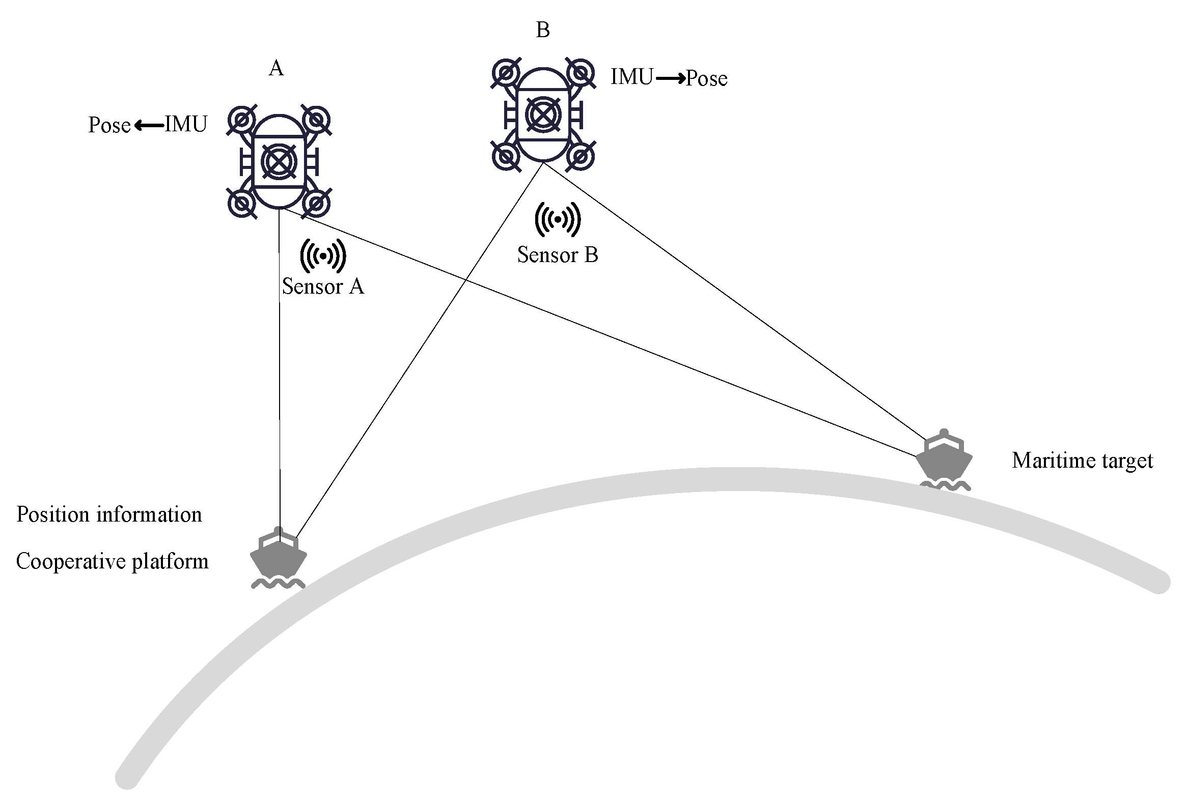
At the moment k, the observation information (distance, azimuth, elevation) of UAV
A and
B to cooperative platform C and the sea target
T are
,
,
,
. Attitude information (yaw, pitch, roll) of the platform’s own inertial guidance output is
,
. The cooperative platform provides its own accurate geodetic coordinate information
, and the posture is shown in
Figure 1.
The observation information of UAV sensors usually consists of three parts, true value
, systematic error of sensor measurement
, and random error of sensor measurement
, so the observation information of UAVs
A and
B on the target and the cooperative platform are related as follows:
The attitude information of the UAV is also composed of true value
, sensor measurement systematic error
, and sensor measurement random error
, so the attitude information of UAVs
A and
B is related as follows:
The tracking of the target directly from raw data will produce large errors, especially as the influence caused by systematic errors among them is difficult to eliminate, so a method is needed to estimate and reduce the systematic errors of observation data and attitude information without the geodetic coordinates of the observation platforms, so as to complete the accurate tracking of targets at sea.
3. Target Tracking Method
The target tracking method includes mutual observation information based on a cooperative platform, the spatial registration method, and the maritime target tracking method.
3.1. Mutual Observation Information Based on a Cooperative Platform
3.1.1. Mutual Observation Information
The mutual observation information among UAVs is obtained by approximating the observation information of UAVs on a cooperative platform. The cooperative platform is treated as a fusion center. The positions of the UAVs, the cooperative platform, and the maritime target are unified into a local geographic reference system under the fusion center.
The position of the cooperative platform under the local geographic coordinate system centered on platform
A is
where
is the transformation of the unstable carrier coordinate system into the stable carrier coordinate system and the expression is
is the conversion from spherical to Cartesian coordinates and the expression is
Due to the close proximity of the cooperative platform and the UAV, the influence of the curvature of the Earth on the coordinate transformation can be ignored, so the position coordinate of UAV
A in the local geographic coordinate system under the fusion center is approximated as
Similarly, the position coordinate of UAV
B in the local geographic coordinate system under the fusion center is
So far, the positions of UAVs A and B have been unified into the same coordinate system.
Combining Equations (10) and (11), the position of UAV
B in the local geographic coordinate system of UAV
A can be approximately obtained
Therefore, the observation information from UAV
A to UAV
B is
where
is the conversion from Cartesian to spherical coordinates and the expression is
3.1.2. Error Analysis
The Earth coordinates of UAV A and B and the cooperative platform are , , . The transformation matrix of the earth coordinate system to the local geographic coordinate system is .
The true value of the local geographic coordinates of UAV
B at the center of UAV
A is
The approximation of the local geographic coordinates of UAV
B in the center of UAV
A is
Comparing Equations (15) and (16), we can obtain the observation information of UAV
A on UAV
B so that the approximation is approximately equal to the true value, then we need to ensure that
This means that the following two conditions are satisfied: (1) the distance between UAVs A and B cannot be too far; (2) the distance between UAV B and the cooperative platform cannot be too far.
3.2. The Spatial Registration Method
3.2.1. Indirect Observation Information of the Target Based on Mutual Observation
Indirect observation information of the target based on mutual observation can be obtained by means of multiple UAVs. In this paper, we use two UAVs as an example.
Based on the mutual observation information of UAV
A to UAV
B in Equation (16), we can obtain the observation information of UAV
A to the target through UAV
B. The position of the target in the local geographic coordinate system centered on UAV
A is
3.2.2. Spatial Registration Based on the Right-Angle Translation Method
The location of the target in the local geographic coordinate system centered on UAV A is obtained from the direct observation data of the target at sea by UAV A, which is denoted as .
Assuming that both the sensor observation information and the platform attitude information are true, we can obtain
Equation (19) can be extended as follows:
Substitute Equations (10)–(12) into Equation (20):
Considering the true value as a function of measured value and error value, the sensor measurement information and the attitude information are subjected to a first-order Taylor expansion at their measured values. Since systematic and random errors of the measured values are in small quantities compared to true and measured values, a higher order can be approximately ignored and only the first-order term is retained.
Equation (21) can be expanded to
Substitute Equations (1)–(6) into Equation (24); simplification gives
Organize Equation (25) and let
So far, the pseudo-measurement equation to eliminate sensor measurement systematic errors and attitude systematic errors is established as
The specific derivation of this part is shown in
Appendix A.
With the development of various technologies, the sensor measurement error and its own attitude error generally change slowly, and the state equation used for spatial registration [
36] is established as
where
is state noise.
The specific process is shown in
Figure 2.
3.3. Maritime Target Tracking Method
According to the estimated systematic error in Equation (28), the systematic error in Equations (1)–(6) is reduced to obtain the observation information of UAVs A and B to the cooperative platform and the sea target T at the moment k, which are denoted as , , , . The attitude information of the platforms after inertial guidance compensation is and , respectively. The above has completed the estimation of sensor observation errors and platform attitude errors, and then the data are aligned and compensated. Next, we move to the tracking of the target at sea.
In order to fuse the observation information of the two UAVs, it is necessary to transform the observation information of both into a unified coordinate system, and the initial position of the cooperative platform is taken as the fusion center in this paper.
Two different tracking methods are designed according to the motion state of the cooperative platform: one is the tracking method when the cooperative platform is stationary, and the other is the tracking method when the cooperative platform is in motion.
When the cooperative platform is stationary, the fusion center is the position of the cooperative platform, and the geodetic coordinates of the cooperative platform are not required to transform observation information into a unified coordinate system at this time:
However, considering the effect of wind, currents, and other factors, it is difficult to keep the cooperative platform absolutely stationary in the real scenario. Therefore, the motion of the cooperative platform must be considered.
When the cooperative platform is in motion, the tracking and filtering fusion of the target directly using Equations (33) and (34) fails. It is necessary that the cooperative platform needs to send its own high-precision geodetic coordinate information in real time at the current moment to transform observation information into a unified coordinate system.
Transform the target position into geodetic coordinates:
where
is the transformation of local geographic coordinates to geodetic coordinates.
The target position is then transformed into a unified coordinate system based on the initial position information of the cooperative platform
:
where
is the transformation of geodetic coordinates into local geographic coordinates.
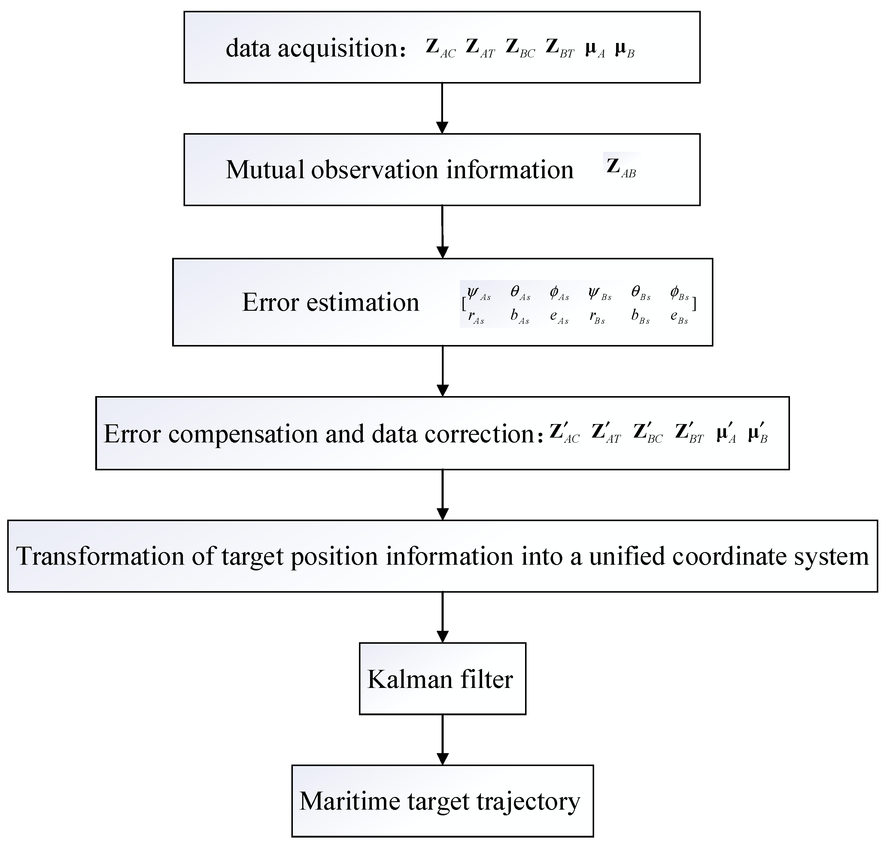
Combined with Kalman filtering to complete the localization and tracking of the target, the specific flow chart is shown in
Figure 3.


