Article

Detection and Classification of Buildings by Height from Single Urban High-Resolution Remote Sensing Images

1
Changjiang River Scientific Research Institute, Changjiang Water Resources Commission, Wuhan 430010, China
2
Research Center on Mountain Torrent and Geologic Disaster Prevention, Ministry of Water Resources, Wuhan 430010, China
3
Changjiang Survey, Planning, Design and Research Co., Ltd., Wuhan 430010, China
4
State Key Laboratory of Information Engineering in Surveying, Mapping and Remote Sensing, Wuhan University, Wuhan 430079, China
*
Author to whom correspondence should be addressed.
Appl. Sci. 2023, 13(19), 10729; https://doi.org/10.3390/app131910729
Submission received: 31 August 2023 / Revised: 20 September 2023 / Accepted: 25 September 2023 / Published: 27 September 2023
(This article belongs to the Special Issue Applications of Remote Sensing and GIS in Land and Soil Resources)

Abstract

:
Recent improvements in remote sensing technologies have boosted building detection techniques from rough classifications using moderate resolution imagery to precise extraction from high-resolution imagery. Shadows frequently emerge in high-resolution urban images. To exploit shadow information, we developed a novel building detection and classification algorithm for images of urban areas with large-size shadows, employing only the visible spectral bands to determine the height levels of buildings. The proposed method, building general-classified by height (BGCH), calculates shadow orientation, detects buildings using seed-blocks, and classifies the buildings into different height groups. Our proposed approach was tested on complex urban scenes from Toronto and Beijing. The experimental results illustrate that our proposed method accurately and efficiently detects and classifies buildings by their height levels; the building detection rate exceeded 95%. The precision of classification by height levels was over 90%. This novel building-height-level detection method provides rich information at low cost and is suitable for further city scene analysis, flood disaster risk assessment, population estimation, and building change detection applications.

1. Introduction

Precise building information is increasingly required for urban monitoring [1,2], urban planning [3,4], and population estimation [5,6]. Remote sensing technology is a cost-optimal, efficient, and popular way to acquire large-scale urban information [2,3,6,7,8,9,10]. Over the years, remote sensing data acquisition capacities have greatly improved in both spatial and temporal resolution. High spatial-resolution images provide a basis to study the urban details of an area, such as buildings. However, it also creates new problems such as limited spectral resolution, high heterogeneity, and shadows. In fact, a large number of urban high spatial resolution images, such as those obtained from Google Earth, exist without parameters for solar zenith angles, exhibiting large-area shadows and RGB bands. Thus, building detection is a topic of interest in high resolution imagery research [10].
Many effective algorithms have been proposed for building information extraction. These building detection methods can be roughly classified into two groups: two-dimensional (2D) and three-dimension (3D) building detection methods. The 2D methods generally extract buildings using brightness, shape, texture, and concomitant shadows [11,12,13,14,15,16,17,18,19,20]. Huang and Zhang [11] developed a morphological building index (MBI) to extract buildings using brightness, size, and shape. However, the MBI method cannot easily distinguish buildings from bare soil and roads, and it fails to detect dark and heterogeneous roofs. Peng et. al. [21] applied and improved the snake model in initial seeds selection and the external energy function to extract buildings. In 2010, Ahmadi et al. [22] proposed a new active contour model based on level set formulation, avoiding initial curves.
Shadow information is frequently used in building detection. Ok et al. [18] introduced a fuzzy landscape generation method to model the relationship between buildings and their shadows and then used GrabCut partitioning to locate regions with buildings. Chaudhuri et al. [19] employed morphology and internal gray variance to describe building edges and their accompanying shadows to extract buildings. Guo and Du [20] used shadows to verify the existence of buildings and confirm building candidates. Huang and Zhang [23] added concomitant shadows of buildings to improve detection accuracy. In 3D building detection methods, height information can facilitate building extraction. The earliest 3D methods for building detection focused on a monocular aerial image with detailed tilt angle, swing angle, and sun altitude [24,25], then calculated the building height according to the shadows and angles. Thus, shadows not only help to extract buildings, but also provide useful information to infer the height of buildings.
In recent years, new remote sensing technologies have emerged to monitor cities. light detection and ranging (LiDAR) is a popular way to obtain the height information for ground objects, and buildings are extracted based on height [26,27,28,29]. Stereo imagery and photogrammetry are applied to building detection, but with more precise and detailed information requirements [30]. Generally, in almost all 2D building detection methods, the results are visualized as binary, separating areas into built-up and not-built-up zones. Urban scenes, however, have become more complex, with denser buildings and population. Hence, binary building detection results might not meet the requirements to detect and describe buildings of different appearances and shapes. The 3D building extraction methods yield height information that can provide a more detailed description of buildings. However, more information, data sources, time, and production costs are required, and the coverage of interest area remains limited. Furthermore, the historical data suitable for 3D methods is less extensive than the data available for analysis with 2D methods. Thus, building detection in two dimensions remains the preferred method in many urban application scenarios.
In building height estimation by shadows, many high-level remote sensing products are already calibrated; the parameters, such as digital orthophoto products and images from Google Earth indicating the solar altitude and sun height, are lost. This means that shadow direction cannot be calculated with parameters taken directly from the image. Most recently, Qi et al. [31] proposed building height estimation using shadows from Google Earth images, with some provided building heights as a references. Liasis and Sravrou [32] also applied shadow length, combined with predefined shadow length, or estimated solar elevation angle to estimate building height.
As shadows can still roughly differentiate the height of the buildings without related angle data or some building heights, we propose a building detection and height-classification algorithm that mines shadow information from images with large-area shadows, requiring only RGB information. The mined shadow information includes the shadow size, shadow edge, shadow direction, and shadow length. We use the shadow size and edge to determine the shadow direction and then generate seed-blocks based on the shadow direction. Aided by shadow length and its distribution, our method semi-automatically groups buildings into three layers: low-rise buildings, middle rise-buildings, and high-rise buildings, labeling them in different colors; this information can be applied to flood disaster risk assessment, population estimation, and building change detection.
The main differences between the proposed algorithm and the previous 2D building detection methods are as follows:
  • As a method for urban images with large-area shadows, it fully utilizes the shadow information to detect and classify buildings.
  • There are lower requirements for image quality, as only RGB band information is used to extract buildings and classify them by height levels. The information of reference height or related angle information is not required.
  • The proposed approach could use seed-blocks to detect buildings with high precision and a low missed detection rate.
This study consists of six main sections. The first includes a literature review of the subject of the study, the second details the study areas, the third introduces the methodology, the forth shows the results and an analysis, the fifth comprises the discussion regarding errors and applications, and the last presents the conclusion.

2. Experimental Data and Study Areas

Urban scenes in different regions have different appearances related to variation in cultural, social, and economic development patterns. We selected two sites with different layouts: Toronto, Canada, and Beijing, China. Both sites reflect complex urban scenes, including buildings at different heights, and different seasons. To verify the adaptability of the proposed method, the experimental data was collected from Google Earth. The details of the experimental data are shown in Table 1.
Table 1 shows basic information about the imagery for the cities of Toronto and Beijing. The images were obtained from different scenes at different resolutions to test the robustness of our proposed approach. The acquisition time of the data from Google Earth is accurate to one day. As the images in the experiments reflect different sizes, we resampled them and arranged them side by side in Figure 1.
Figure 1a shows the urban scene in Toronto in summer. Most of the tall buildings lie from the center to the right of the image, while the residential areas are located in the center-left of the image. The vegetation is spread over the entire image, as seen in Figure 1a. Figure 1b shows Beijing in winter. High-rise buildings lie along the street and in the center. The vegetation is very limited in the scene because of the season and location.

3. Methodology

The aim of this paper is to fully mine shadow information to detect and classify buildings according to height level in an urban high-resolution image with large-area shadows. The key steps in this process are introduced in this section, including shadow obtaining, shadow direction acquisition, building detection, and height classification. A flowchart of our method is shown in Figure 2.
As shown in Figure 2, we first obtain the shadows and apply a morphological open operation to disconnect them from each other. Large-sized shadows are filtered out, and shadow edges are used to acquire the shadow direction. Based on shadow direction, seed-blocks are generated in locations where buildings are likely located. Overlapping objects with color and texture features similar to those of the seed-blocks in reliable areas are recognized as buildings. We judge building height levels based on the shadow length, labeling each height group in different colors.

3.1. Shadow Detection

In urban areas, the majority of objects that create shadows are buildings. Therefore, shadow information is frequently used to extract buildings from high-resolution images. We employ information from shadows to detect buildings in urban areas. A variety of shadow detection algorithms have been proposed in previous works [15,33,34,35]. In our work, we used the existing shadow detection methods at the object level [15] and pixel level [33]. The shadow detection result is recorded as SHa. Any shadow detection method can be used, as long as the shadow detection results are highly accurate.

3.2. Shadow Direction Acquisition

Shadow direction indicates the location relationship between buildings and their shadows. As high-level, high-resolution image products are already calibrated, the parameters that indicate the solar altitude and sun height are the default. This means that shadow direction cannot be calculated with parameters taken directly from the image. This step obtains the shadow direction by the area and shape of the shadows. Since an image covers a certain area at similar times, the direction of the shadows in a single high-resolution image can be regarded as the same.

3.2.1. Shadow Filtered by Area

Large-area shadows appear in the cloud-free image for two reasons. First, a low solar attitude and high-rise buildings generate large shadows. Second, a dense arrangement of buildings may cause shadows to connect into large continuous areas. Our objective is to screen out the shadows generated by high-rise buildings, as the edges of which can indicate shadow angles. The shadow angle θ refers to the angle between the shadow orientation and the north–south axis, where θ [ 90 , 90 ] . The two steps to obtain the shadow angle are as follows.
A morphological opening operation is applied to separate all the shadows. An open operation effect depends on the structuring element (SE) and its size. As the large-size shadows are the targets, the structuring size must be a relatively large value to separate large, conjoined shadows, maintaining the shape of single shadows. The disk was chosen as the SE. The shadow result after open operation is called SHb.
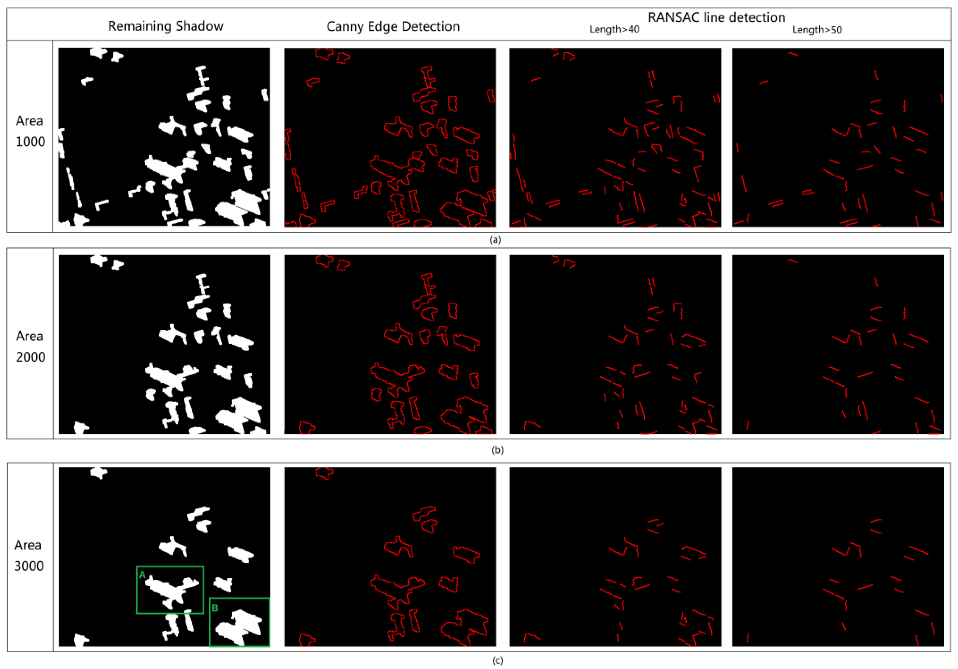
Set a threshold A for the area to extract the large-area shadows from high buildings. Filtered shadow results were recorded as SHc. To simplify the operation and ensure a correct result for the shadow angle, we chose three thresholds. There is a large range for threshold choices, so we chose those around the top 8% value in the descending order of the area as the middle threshold A2. And the other two thresholds A1 and A3 are defined as:
A 1 = A 2 a
A 3 = A 2 + a
In Equations (1) and (2), the value of a depends on the image resolution, usually set from 100 to 1500 pixels. Usually, all of A 1 , A 2 and A 3 are useful for large-area shadow extraction, as shown in Figure 3. The threshold could also be set manually and empirically.

3.2.2. Estimating the Shadow Angle

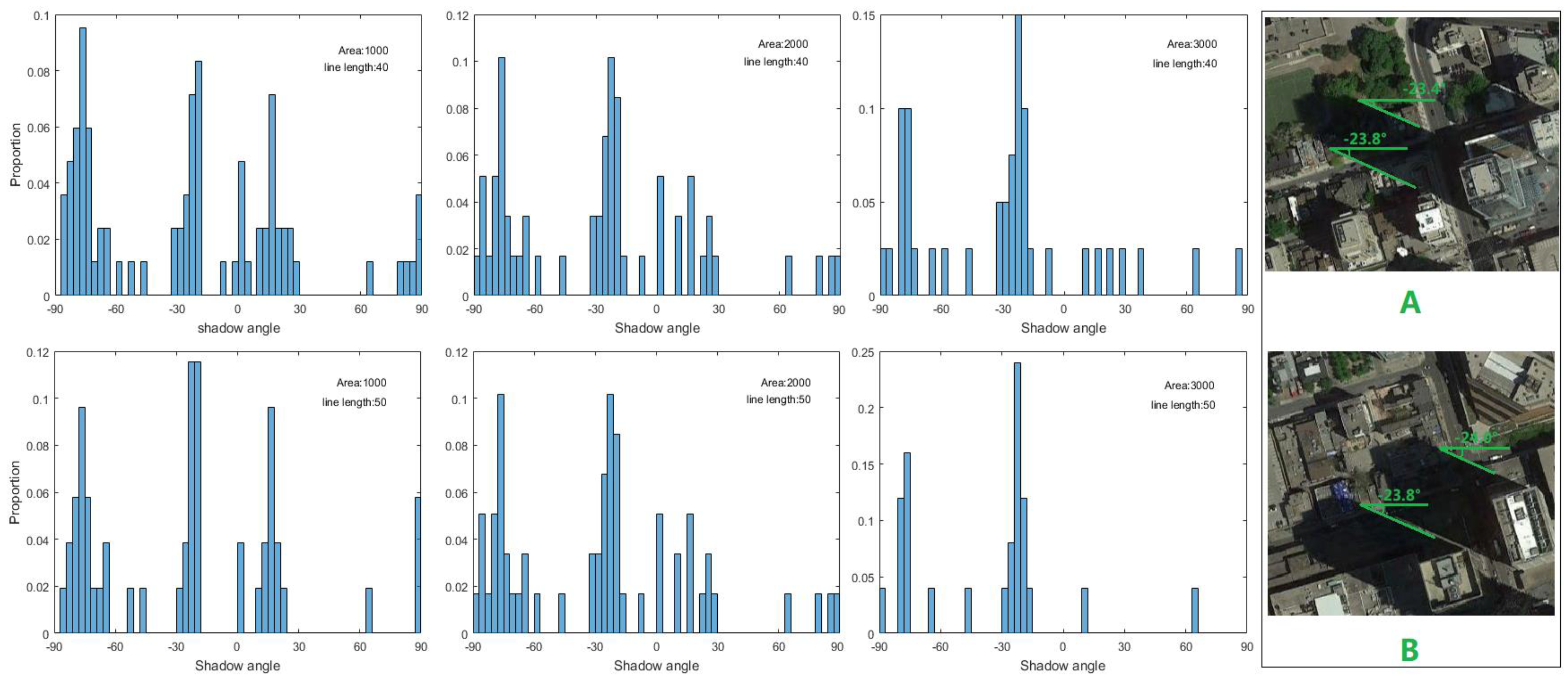
Because the high-rise building shadows most likely exhibit shadow angles with long straight lines, here, two typical and effective algorithms were introduced to find these line features: the Canny edge detector [36] and random sample consensus (RANSAC) [37]. We detected shadow edges on SHc with the Canny edge detector, and the result was recorded as EG. After Canny edge detection, each connected domain in EG was set as a unit. We used RANSAC to detect inliers in every unit. The inliers are the points that can be fitted to the line, and the outliers are the points not on the line. Next, we set the length thresholds of the line. Empirically, we set two length thresholds according to the resolution and shadow size, recorded as L1 and L2. Figure 3 shows the results of different area thresholds and different lengths of lines. At last, we count the number of lines at each angle obtained by RANSAC for different area thresholds and for different lengths of lines, as shown in the histograms in Figure 4. We sum up the proportions in every case; the angle that has the largest value is the shadow angle θ.
Figure 3 illustrates the process of shadow angle detection; the corresponding original image is shown in Figure 2a. In this example, the morphological structure is the disk for the shadow detection result, and the open operation size for SE is 7. The remaining shadow results are shown in the second column in Figure 3; the area thresholds were 1000, 2000, and 3000 pixels respectively. The last two columns display the RANSAC line detection results with different length thresholds. The angles of the lines in different cases are seen in Figure 4. The original scenes in the green boxes A and B in Figure 3c correspond to the partial original images A and B in Figure 4. When comparing the shadow angle value and the true shadow angle in Figure 4, the proposed method correctly obtained the shadow angle. Combining Figure 3 and Figure 4, we found that the larger the area and length threshold chosen, the fewer lines remained, and the larger the proportion of the true shadow angle. If a is set as 500 pixels, or the A2 is set as 1500 pixels, the correct shadow angle can still be determined. Hence, this method is robust for shadow angles.

3.2.3. Shadow Direction Confirmation

To confirm shadow direction, we first check the latitude and the collection date of an image to determine the shadow directly. Table 2 shows the general shadow directions at different times and locations.
In Table 2, shadow direction is roughly south, north or uncertain, using Table 2 and θ, the shadow direction can be confirmed. If the image belongs to the uncertain cases, we use the gray and topological features to ascertain the direction, as shown in Figure 5.
In Figure 5, θ refers to shadow angle without direction, and areas ( B 1 , B 2 ) are extracted at the sides of the shadow on the shadow angle of SHc. A shadow direction candidate α 1 and α 2 are the two directions of a shadow angle. If the building is on the B1 side, the shadow direction is α 2 . If the building is on the B1 side, the shadow direction is α 1 . To ascertain the shadow direction in this case, we make gray value comparison between the B 1 s and B 2 s:
f ( B ) = { 1 , G B 1 > G B 2 0 , G B 1 < G B 2
M = i = 1 N f ( B )
α = { α 1 ,   M < N / 2 α 2 ,   M > N / 2
In Equation (3), G B 1 is the average gray value of B 1 , and G B 2 is the average gray value of B 2 . In Equation (4), shadow direction is α and α [ 180 ° , 180 ° ] . In Equation (5), N represents all the shadows involved in the calculations. In theory, it is unlikely that M = N/2. If M = N/2, obtain another area threshold and repeat this step. Lastly, a manual sampling check is applied in the event that an extreme case occurs; for example, if θ equals 0.

3.3. Building Detection

Shadows could provide location and height information for building detection. With the assistance of shadow information, buildings are detected and classified into three layers: low-rise buildings, medium-rise buildings, and high-rise buildings. The processes contain seed-block generation, reliable areas setting, building detection, and building height-classification. Reliable areas refer to the areas that have a high possibility of containing buildings; and the fractal net evolution approach (FNEA) [38], widely used in object-oriented image analysis, is employed for segmentation.

3.3.1. Seed-Block Generation

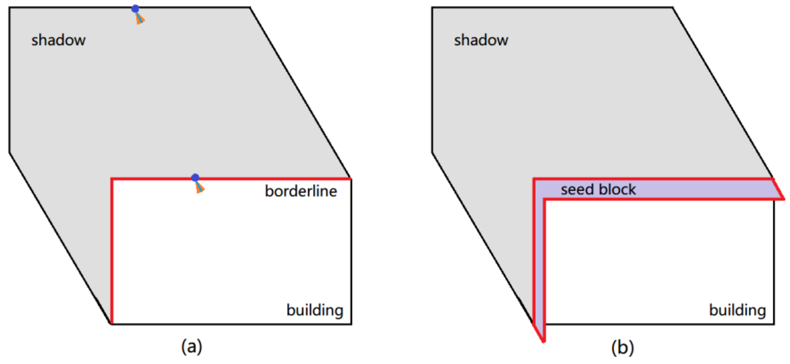
A seed-block is a block that functions like a seed, a part of a building that could provide information about location, brightness, and even shape for building detection. The process of seed-block generation is shown in Figure 6.
In Figure 6a, the blue line has a direction opposite to the shadow direction, and the orange sector region is blue-line-centered and 5° on both sides. There is a one-to-one correspondence sector region for the points on the shadow edges. The sector regions are examined to detect the borderlines. If the entire sector region is out of the shadow region, the corresponding shadow edge point is regarded as the borderline between shadows and buildings. If the sector region partially falls into the shadow region, the corresponding edge point is regarded as a normal edge point and is left out. In Figure 6b, the points on the borderline between a shadow and a building are shifted slightly in the direction opposite of the shadow. The seed-block is composed of that area that is circled by the shifted line and the original borderline. It is located along the edge between the shadow and the building.
Objects other than buildings that generate shadows may be mistaken for buildings. Errors are mainly the result of trees. Trees can complicate building detection in urban areas. Trees have different side effects on building detection. In the growing season, trees create a large amount of shadows, which could also generate seed-blocks in building detection. To solve this problem, we detect vegetation areas and then delete the seed-blocks that fall into the vegetation areas; color vegetation indices [39] were used for vegetation detection. In the fall foliage season, trees without leaves have a limited effect on building detection using their shadows. However, vegetation could still have an effect stemming from their color. In some remote sensing images, vegetation might exhibit low brightness, so some trees are recognized as shadows and are hard to detect. In this case, we check the brightness for every seed-block and delete the seed-blocks with low brightness.

3.3.2. Set Reliable Areas for Buildings

According to the shadow direction and the borderline between a building and its shadow, a reliable area is generated using the following rules. The diagrams for each rule are shown in Figure 7.
Rule 1: Two borderlines exist in vertical angles, and two lines have similar length (the difference is less than a half-length of the shorter line). Shift the lines in the shadow direction with a very short distance, and extend the lines on the other side, creating parallel lines. The reliable area is shown in Figure 7a. The extended length is no longer than one-third the length of the original borderline.
Rule 2: Only one main borderline exists, as shown in Figure 7b. The lines in different angles are short. Shift the main line in the shadow direction with a short distance, extend the line on both sides, and create parallel lines in the vertical direction of the extended line. The shifted lines and the vertical parallel lines comprise the reliable area, as shown in Figure 7b. Considered as general cases, the length of the extended lines depends on resolution; usually, the border-extended line is set to less than 10 pixels. The length of the vertical parallel lines is no more than three times that of the main border line.
Rule 3: If the reliable areas contact each other, or if one reliable area contains another, find the combined reliable area, as shown in Figure 7c.

3.4. Building Height-Classification

The length of the shadows accompanying buildings reflects the height of the buildings. According to shadow length, we classify the building into three height groups: low-rise buildings, medium-rise buildings, and high-rise buildings. To measure the shadow length, we rotated the image θ degrees clockwise, when θ is not less than 0, and rotate the image θ degrees counterclockwise, when θ is less than 0. Then we calculate the length using a horizontal scanning line and record the length of the scanned parts of the shadows. The scanning density is one pixel. The threshold can be manually set as required, such as for flood disaster risk assessment, which can be applied to estimate the number of people who could survive in the event that the buildings were flooded.
To measure the shadow length, we rotate the image θ degree clockwise, when θ is not less than 0, and rotate the image θ degree counterclockwise when θ is less than 0. Next, we calculate the length using a horizontal scanning line and record the length of the scanned parts of the shadows. The scanning density is one pixel, and the longest length of the neighboring n lines is the recorded length. n depends on the resolution and n ∈ [0, 5]. Finally, we judge the height level according to the shadow length. Figure 8 illustrates the length measurement procedure. The thresholds for filtering the area and differentiating the shadow length are determined manually and depend on the image resolution and shadow scale.

4. Results and Analysis

4.1. The Toronto Urban Scene

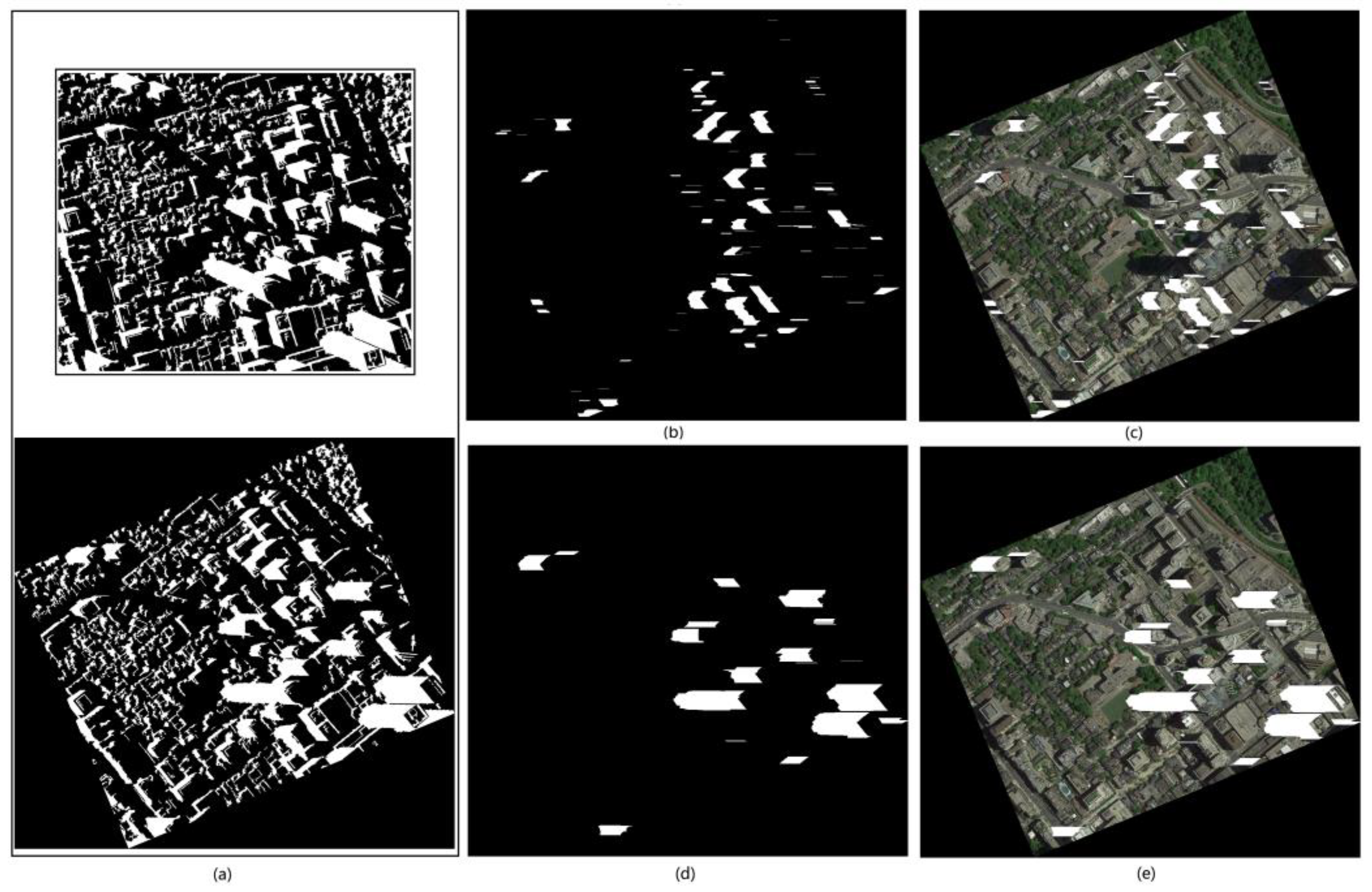
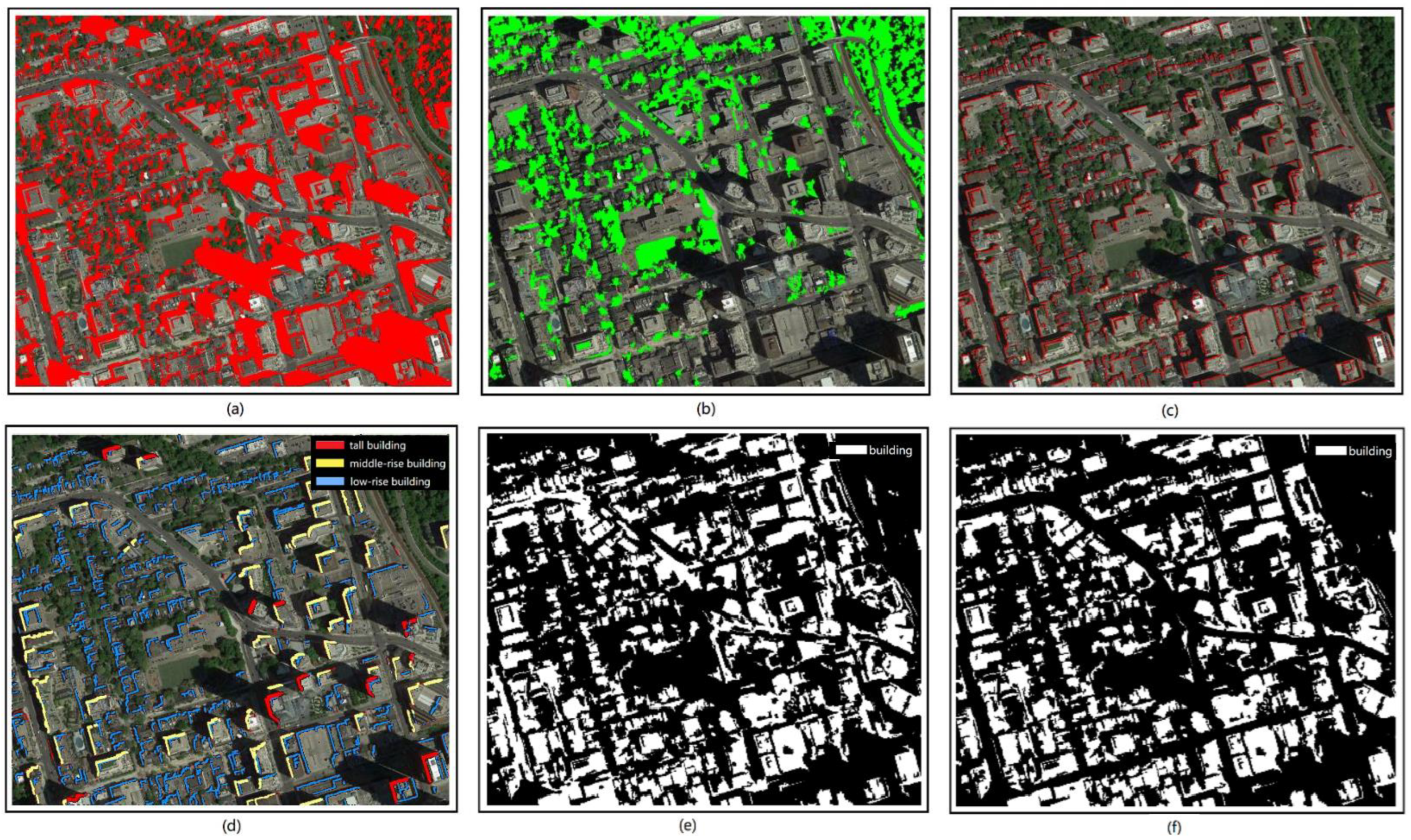
The results of the steps for building detection and classification are shown in Figure 9a–d. The middle-step results include shadow detection, vegetation detection, and seed-block generation, excluding the tree seed-blocks, and the building detection and height-classifications are shown in Figure 9d. We applied object-based random forest (RF) [40] to detect the buildings for comparison. The RF result for the buildings is shown in Figure 9e. Figure 9f shows the buildings after excluding road areas misjudged as buildings.
Figure 9a,b shows the results of shadow detection and vegetation detection. After shadow detection and vegetation detection, we acquired seed-blocks from the opposite side of the shadow and excluded the tree effect, as shown in Figure 9c. The seed-blocks provided accurate information for buildings. To exclude the tree effect, the seed-blocks that fell in the vegetation areas were deleted. Figure 9d shows the final result for buildings in different height levels. The final result also reveals that the majority of buildings with middle and high height levels are on the right side of the image, and the small, low buildings were located mainly in the center left of the result. Comparing Figure 9d and original image in Figure 1a, the results are in accordance with the buildings in the original image. This illustrates that shadow length is useful information when judging the height level of buildings.
We also quantitatively estimate the accuracy of our results. For the Toronto scene, the true buildings that we extracted are based on the same segmentation FNEA as our method. As we used multi-scale segmentation, the final result was estimated in pixels. WH shows that the building object is judged at the incorrect height level. The analysis of the precision, recall, omission, and false alarm rates are defined in Ref. [41] and shown in Table 3.
In Table 3, the precision of the related parameters of buildings and impervious ground were both below 80%. With the help of shadow, we can make a distinction between buildings and impervious ground, to a great extent. According to true building data, the recall of complete building extraction reaches 89.8%, while the false detection and incorrect height judgment were less than 0.5%, with a total precision of about 98%. The omission of building detection was over 10% due to the buildings fell in the shadows. This means that the building detection recall will rise to 94% when ignoring the buildings located in shadows. The accuracy of the height judgment was 97% in visual interpretation; thus, shadow information is reliable when used to roughly estimate the height levels of buildings.

4.2. The Beijing Urban Scene

A set of experiments in Beijing demonstrate building detection and height-classification using shadow information at the pixel level. The building detection results and subsequent analysis are visualized in Figure 10.
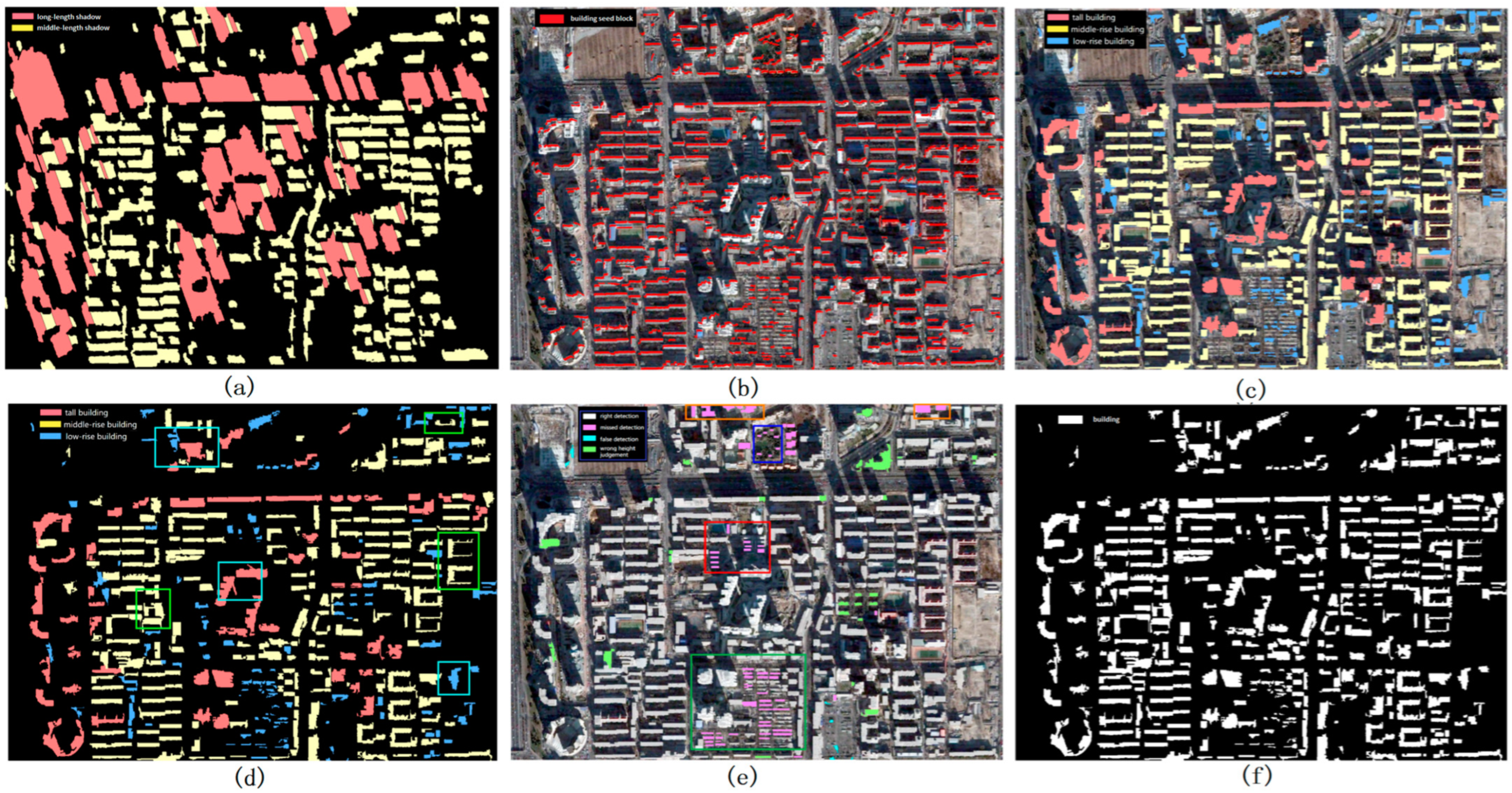
The original image is shown in Figure 1b. The results of the length measurements of the shadows are shown in Figure 10a—red represents the long length; yellow represents the middle length. Figure 10b shows the results of seed-blocks generation. The building detection and height-classification results are shown in Figure 10c, from which we can see that most buildings have been accurately detected and properly classified with different height levels. The shape of the buildings is still a problem, as shown in the boxes of Figure 10d. Considering that a building was detected correctly, regardless of the shape, differences between the ground truth and the results from our method are marked in different colors in Figure 10e, and the errors include omissions marked in pink, false alarms marked in blue, and incorrect height judgments marked in green. Figure 10c,f shows a binary image displaying only building locations. Thus, our building height-classification results can better explain buildings in urban scenes.
For the Beijing scene, the buildings are countable in the image. We classified the buildings into three height levels, and counted the number of buildings in each level. There were two cases of incorrect height judgments: when the entire building is recognized at an incorrect height level, it is recorded as WWH, and when part of building is given the incorrect height, it is recorded as PWH. The related Beijing data is shown in Table 4.
In Table 4, it is revealed that the number of buildings in ground truth was 439, the number of correctly detected and classified buildings was 354, and the number of building detected by our method was 386. Irrespective of the height, the precision of our method exceeded 98% in building detection. When considering the height of a building, the precision dropped to 91.6%. The recall of the building detection was 87.1%, and went down to 81.4% when correct height-classification was added. The precision and recall of high and middle level buildings detection and classification were over 95%. However, the recall of the low level buildings was only 66.8%, while the precision remained very high, at over 90%. There were 61 undetected buildings, in which 57 undetected buildings belonged to low level. The recall of total building detection rose to 95.4%, and reached 90.7% when considering correct height classification. The number of false alarms was maintained in the single digits, and erroneous height judgment occurred for less than 6% of the total buildings. Therefore, shadow information is valuable and effective in building detection and height-classification, although it is not reliable enough for detecting low-level buildings.

5. Discussion

5.1. Discussion regarding Errors

The experiments in both Toronto and Beijing illustrate that buildings and impermeable ground are easily confused, especially in road regions. In the Toronto scene, in Table 3, the precision of buildings increased from 72.5% to 78.2% when roads were removed. In the Beijing scene, as shown the blue box in Figure 10d, we found that although the buildings were discovered, parts of their surroundings were also incorrectly regarded as buildings when the surroundings were combined into the same object. At the same time, the green box in Figure 10d shows that parts of buildings in low brightness caused by shadows cannot be recognized. The same thing also occurs in Toronto building detection. In Figure 10e, we can see that omissions stem from low-height buildings in shadows (circled in red boxes), next to trees (circled in green boxes), on the edges of images (circled in orange boxes), with low gray value (circled in blue boxes), and with missing shadows (pink color outside the boxes). The false alarm, caused by buses or other ground objects that creaste shadows, was very limited and occurred in small sizes. Erroneous height judgments occur when shadows are cut by an object like buildings, trees, misclassified bright roads, or the edge of an image. Connected buildings at different heights might be labeled as the highest height level, which means buildings might be classified into the incorrect height level.
The shadow information affected by trees and neighboring buildings is not very reliable. The main problem is this regard is the low-level buildings detected with a relatively low accuracy. A method used in Ref. [42] that detects areas with the low and dense buildings could alleviate this problem to some extent.

5.2. Potential Application

Recently, coupled with climate change and human activities, the frequency and intensity of extreme rainfall have increased, leading to mountain flooding and urban waterlogging. Flooding and waterlogging disasters not only cause devastating damage to infrastructure, but also pose great threats and damage to people’s lives and safety. When a flood or storm occurs, people usually flee to a high place to avoid risk. Through the proposed method, we can quickly distinguish the buildings that can avoid disaster (tall buildings) and the buildings that may be flooded (low buildings), assess the survival environment when the flood occurs, and provide technical support for emergency rescue. As shown in Figure 11 below, by combining the building height level and DEM in the Beijing scene, we could estimate that the people living in the low buildings of the low DEM areas (orange to red in the DEM figure) are at a relatively high risk of being inundated by urban waterlogging.

5.3. Discussion of Application

In our method, the shadow angle is not used to calculate the height of the buildings, but is used to calculate the length of the shadows for classifying the buildings into different height levels, according to the obtained shadow lengths. In practice, we suggest choosing a building with a known height as a reference to assist in height classification and obtaining the approximate height of the building.
In regards to computational complexity and processing time, these depend on threshold selection and computer performance. Most steps, such as shadow detection, RANSAC, etc., are simple and classical, and could be run automatically. It takes less than 3 min for our experiments to be completed, if the proper threshold is set.
For the availability and quality of image selection, the proposed method is adapted for high spatial resolution images, with large-scale shadows that could distinguish building in different height levels using a visual interpreter. Both high resolution and shadows are essential in our purposed method. The method shows relatively low sensitivity to environmental factors such as different lighting or weather conditions because the problem could be solved by methods of image enhancement and other ways. For example, as the vegetation in winter is too dark to be accurately detected from the Beijing image, we did not extract vegetation in the experiment. Instead, we eliminated the dark seed-blocks because some dark trees were mistaken as shadows, leading to incorrect seed-blocks, while buildings exhibited a brighter value. If the images is captured under low light conditions, it requires enhancement, such as linear stretching, filtering, etc.
For the height level, the range of low, middle, and high height in our experiments corresponds to 0–15 m, 15–50 m, and higher than 50 m, respectively. We also suggest classifying the height manually, into fewer or more groups, according to the actual demand, which we also mentioned in regards to the thresholds in this work.

6. Conclusions

We propose a novel building-detection and height-classification method using shadow information from single high-resolution remote sensing images. To verify the proposed method, we selected experimental sites in different layouts from Toronto and Beijing to detect and classify the buildings into different height levels. The buildings were not only accurately detected, but were also properly classified at different height levels using our method. Easily available data are adequate for our building detection and height-classification method, as the solar angle is not required, which enables the analysis of complex urban scenes and might be of value for other applications such as flood survival assessment, urban change detection, and population estimation. Compared with binary detection results from 2D building detection methods, the rough height level estimation and building distribution results are suitable for further applications, such as city scene analysis and building change detection.
The limitations of computational complexity and processing time, the requirements of image selection, the sensitivity of the environments, and height thresholds should be explored in future studies.

Author Contributions

H.Z., K.S. and D.L. conceived and designed the framework of this research. H.Z. and C.X. performed the experiments; W.L. contributed the analysis tools; Z.F. contributed the pro-processed data; and H.Z. wrote the paper. All authors have read and agreed to the published version of the manuscript.

Funding

This work is supported by the National Key R&D Program of China (No. 2021YFE0111900, No. 2021YFC3200202), the Key Research Project of Water Conservancy in Hubei Province (No. HBSLKY202208), the Natural Science Foundation of China (No. 41902300), and independent scientific research projects of CISPDR (NO. CX2021Z10-1).

Institutional Review Board Statement

Not applicable.

Informed Consent Statement

Not applicable.

Data Availability Statement

Experimental data from this study will be available upon request.

Conflicts of Interest

The authors declare no conflict of interest.

References

  1. Khoshelham, K.; Nardinocchi, C.; Frontoni, E.; Mancini, A.; Zingaretti, P. Performance evaluation of automated approaches to building detection in multi-source aerial data. ISPRS J. Photogramm. Remote Sens. 2010, 65, 123–133. [Google Scholar] [CrossRef]
  2. Shao, Z.; Cheng, T.; Fu, H.; Li, D.; Huang, X. Emerging Issues in Mapping Urban Impervious Surfaces Using High-Resolution Remote Sensing Images. Remote Sens. 2023, 15, 2562. [Google Scholar] [CrossRef]
  3. Wellmann, T.; Lausch, A.; Andersson, E.; Knapp, S.; Cortinovis, C.; Jache, J.; Haase, D. Remote sensing in urban planning: Contributions towards ecologically sound policies? Landsc. Urban Plan. 2020, 204, 103921. [Google Scholar] [CrossRef]
  4. Akçay, H.G.; Aksoy, S. Building detection using directional spatial constraints. In Proceedings of the 2010 IEEE International Geoscience and Remote Sensing Symposium (IGARSS), Honolulu, HI, USA, 25–30 July 2010; IEEE: Piscataway, NJ, USA, 2010; pp. 1932–1935. [Google Scholar]
  5. Collins, W.G.; El-Beik, A. Population census with the aid of aerial photographs: An experiment in the city of leeds. Photogramm. Rec. 1971, 7, 16–26. [Google Scholar] [CrossRef]
  6. Wu, S.-S.; Qiu, X.; Wang, L. Population estimation methods in gis and remote sensing: A review. GIScience Remote Sens. 2005, 42, 80–96. [Google Scholar] [CrossRef]
  7. Taubenböck, H.; Esch, T.; Felbier, A.; Wiesner, M.; Roth, A.; Dech, S. Monitoring urbanization in mega cities from space. Remote Sens. Environ. 2012, 117, 162–176. [Google Scholar] [CrossRef]
  8. Patel, N.N.; Angiuli, E.; Gamba, P.; Gaughan, A.; Lisini, G.; Stevens, F.R.; Trianni, G. Multitemporal settlement and population mapping from Landsat using Google Earth Engine. Int. J. Appl. Earth Obs. Geoinf. 2015, 35, 199–208. [Google Scholar] [CrossRef]
  9. Bai, T.; Wang, L.; Yin, D.; Sun, K.; Chen, Y.; Li, W.; Li, D. Deep learning for change detection in remote sensing: A review. Geo-Spat. Inf. Sci. 2022. [Google Scholar] [CrossRef]
  10. Yonaba, R.; Koïta, M.; Mounirou, L.A.; Tazen, F.; Queloz, P.; Biaou, A.C.; Yacouba, H. Spatial and transient modelling of land use/land cover (LULC) dynamics in a Sahelian landscape under semi-arid climate in northern Burkina Faso. Land Use Policy 2021, 103, 105305. [Google Scholar] [CrossRef]
  11. Huang, X.; Zhang, L. A multidirectional and multiscale morphological index for automatic building extraction from multispectral geoeye-1 imagery. Photogramm. Eng. Remote Sens. 2011, 77, 721–732. [Google Scholar] [CrossRef]
  12. Myint, S.W.; Lam, N.S.-N.; Tyler, J.M. Wavelets for urban spatial feature discrimination. Photogramm. Eng. Remote Sens. 2004, 70, 803–812. [Google Scholar] [CrossRef]
  13. Zhou, G.Q.; Sha, H.J. Building Shadow Detection on Ghost Images. Remote Sens. 2020, 12, 679. [Google Scholar] [CrossRef]
  14. Pesaresi, M.; Gerhardinger, A.; Kayitakire, F. A robust built-up area presence index by anisotropic rotation-invariant textural measure. IEEE J. Sel. Top. Appl. Earth Obs. Remote Sens. 2008, 1, 180–192. [Google Scholar] [CrossRef]
  15. Zhang, H.; Sun, K.; Li, W. Object-oriented shadow detection and removal from urban high-resolution remote sensing images. IEEE Trans. Geosci. Remote Sens. 2014, 52, 6972–6982. [Google Scholar] [CrossRef]
  16. Shi, L.; Zhao, Y. Urban feature shadow extraction based on high-resolution satellite remote sensing images. Alex. Eng. Journa 2023, 77, 443–460. [Google Scholar] [CrossRef]
  17. Sirmacek, B.; Unsalan, C. Building detection from aerial images using invariant color features and shadow information. In Proceedings of the 2008 23rd International Symposium on Computer and Information Sciences, ISCIS’08, Istanbul, Turkey, 27–29 October 2008; IEEE: Piscataway, NJ, USA, 2008; pp. 1–5. [Google Scholar]
  18. Ok, A.O.; Senaras, C.; Yuksel, B. Automated detection of arbitrarily shaped buildings in complex environments from monocular vhr optical satellite imagery. IEEE Trans. Geosci. Remote Sens. 2013, 51, 1701–1717. [Google Scholar] [CrossRef]
  19. Chaudhuri, D.; Kushwaha, N.; Samal, A.; Agarwal, R. Automatic building detection from high-resolution satellite images based on morphology and internal gray variance. IEEE J. Sel. Top. Appl. Earth Obs. Remote Sens. 2016, 9, 1767–1779. [Google Scholar] [CrossRef]
  20. Guo, Z.; Du, S. Mining parameter information for building extraction and change detection with very high-resolution imagery and gis data. GIScience Remote Sens. 2017, 54, 38–63. [Google Scholar] [CrossRef]
  21. Peng, J.; Zhang, D.; Liu, Y. An improved snake model for building detection from urban aerial images. Pattern Recognit. Lett. 2005, 26, 587–595. [Google Scholar] [CrossRef]
  22. Ahmadi, S.; Zoej, M.V.; Ebadi, H.; Moghaddam, H.A.; Mohammadzadeh, A. Automatic urban building boundary extraction from high resolution aerial images using an innovative model of active contours. Int. J. Appl. Earth Obs. Geoinf. 2010, 12, 150–157. [Google Scholar] [CrossRef]
  23. Huang, X.; Zhang, L. Morphological building/shadow index for building extraction from high-resolution imagery over urban areas. IEEE J. Sel. Top. Appl. Earth Obs. Remote Sens. 2012, 5, 161–172. [Google Scholar] [CrossRef]
  24. Lin, C.; Huertas, A.; Nevatia, R. Detection of buildings using perceptual grouping and shadows. In Proceedings of the 1994 Proceedings of IEEE Conference on Computer Vision and Pattern Recognition, CVPR’94, Seattle, WA, USA, 21–23 June 1994; IEEE: Piscataway, NJ, USA, 1994; pp. 62–69. [Google Scholar]
  25. Nevatia, R.; Lin, C.; Huertas, A. A system for building detection from aerial images. In Automatic Extraction of Man-Made Objects from Aerial and Space Images (II); Springer: Berlin/Heidelberg, Germany, 1997; pp. 77–86. [Google Scholar]
  26. Ma, R. Dem generation and building detection from lidar data. Photogramm. Eng. Remote Sens. 2005, 71, 847–854. [Google Scholar] [CrossRef]
  27. Rottensteiner, F.; Trinder, J.; Clode, S.; Kubik, K. Using the dempster–shafer method for the fusion of lidar data and multi-spectral images for building detection. Inf. Fusion 2005, 6, 283–300. [Google Scholar] [CrossRef]
  28. Lao, J.; Wang, C.; Zhu, X.; Xi, X.; Nie, S.; Wang, J.; Zhou, G. Retrieving building height in urban areas using ICESat-2 photon-counting LiDAR data. Int. J. Appl. Earth Obs. Geoinf. 2021, 104, 102596. [Google Scholar] [CrossRef]
  29. Meng, X.; Wang, L.; Currit, N. Morphology-based building detection from airborne lidar data. Photogramm. Eng. Remote Sens. 2009, 75, 437–442. [Google Scholar] [CrossRef]
  30. Qin, R.; Tian, J.; Reinartz, P. Spatiotemporal inferences for use in building detection using series of very-high-resolution space-borne stereo images. Int. J. Remote Sens. 2016, 37, 3455–3476. [Google Scholar] [CrossRef]
  31. Qi, F.; Zhai, J.Z.; Dang, G. Building height estimation using google earth. Energy Build. 2016, 118, 123–132. [Google Scholar] [CrossRef]
  32. Liasis, G.; Stavrou, S. Satellite images analysis for shadow detection and building height estimation. ISPRS J. Photogramm. Remote Sens. 2016, 119, 437–450. [Google Scholar] [CrossRef]
  33. Dare, P.M. Shadow analysis in high-resolution satellite imagery of urban areas. Photogramm. Eng. Remote Sens. 2005, 71, 169–177. [Google Scholar] [CrossRef]
  34. Salvador, E.; Cavallaro, A.; Ebrahimi, T. Shadow identification and classification using invariant color models. In Proceedings of the 2001 IEEE International Conference on Acoustics, Speech, and Signal Processing, Proceedings (Cat. No.01CH37221), (ICASSP’01), Salt Lake City, UT, USA, 7–11 May 2001; IEEE: Piscataway, NJ, USA, 2001; pp. 1545–1548. [Google Scholar]
  35. Wang, Q.; Yan, L.; Yuan, Q.; Ma, Z. An automatic shadow detection method for vhr remote sensing orthoimagery. Remote Sens. 2017, 9, 469. [Google Scholar] [CrossRef]
  36. Canny, J. A computational approach to edge detection. IEEE Trans. Pattern Anal. Mach. Intell. 1986, 6, 679–698. [Google Scholar] [CrossRef]
  37. Fischler, M.A.; Bolles, R.C. Random sample consensus: A paradigm for model fitting with applications to image analysis and automated cartography. Commun. ACM 1981, 24, 381–395. [Google Scholar] [CrossRef]
  38. Baatz, M. Multiresolution segmentation: An optimization approach for high quality multi-scale image segmentation. Angew. Geogr. Inf. Verarb. 2000, 12, 12–23. [Google Scholar]
  39. Meyer, G.E.; Neto, J.C. Verification of color vegetation indices for automated crop imaging applications. Comput. Electron. Agric. 2008, 63, 282–293. [Google Scholar] [CrossRef]
  40. Bai, T.; Sun, K.; Li, W.; Li, D.; Chen, Y.; Sui, H. A novel class-specific object-based method for urban change detection using high-resolution remote sensing imagery. Photogramm. Eng. Remote Sens. 2021, 87, 249–262. [Google Scholar] [CrossRef]
  41. Olson, D.L.; Delen, D. Advanced Data Mining Techniques; Springer Science & Business Media: Berlin/Heidelberg, Germany, 2008. [Google Scholar]
  42. Zhang, H.; Xu, W.; Ren, H.; Dong, L.; Fan, Z. Dense and Low-rise Residential Areas Detection by Shadow Data Mining in Urban High-resolution Images. In Proceedings of the 2021 International Conference on Intelligent Computing, Automation and Applications (ICAA), Nanjing, China, 25–27 June 2021; IEEE: Piscataway, NJ, USA, 2021; pp. 514–519. [Google Scholar]
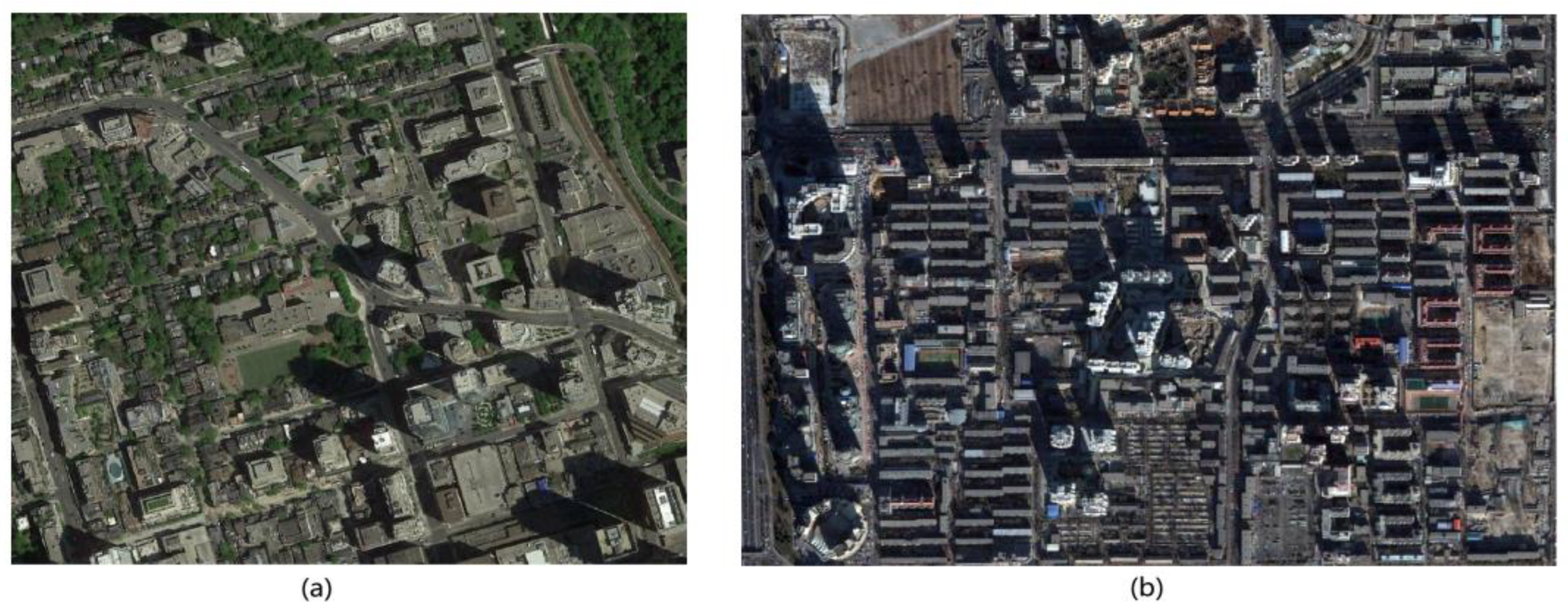
Figure 1. Original images of the study sites: (a) dense building areas in Toronto, Canada; (b) dense building areas in Beijing, China.
Applsci 13 10729 g001
Figure 2. Flowchart of hierarchical building detection based on mining shadow information from single urban high-resolution remote sensing imagery.
Applsci 13 10729 g002
Figure 3. Results (SHc, EG, line detection) of different area thresholds and different lengths of lines. (a) Results of SHc, EG, and line detection when the area equal to 1000 pixels. (b) Results of SHc, EG, and line detection when the area equal to 2000 pixels. (c) Results of SHc, EG, and line detection when the area equal to 3000 pixels, the larger shadows marked as green letters A, B are corresponding to the original parts of the Toronto scene marked in A, B in Figure 4, respectively.
Applsci 13 10729 g003
Figure 4. Histograms of RANSAC line detection in different area threshold and different lengths of lines. The original parts of the Toronto scene marked in A, B are corresponding to the lar shadows marked as green letters A, B in Figure 3, respectively.
Applsci 13 10729 g004
Figure 5. Diagram of shadow direction confirmation.
Applsci 13 10729 g005
Figure 6. Diagram of seed-blocks. (a) Detection of borderlines between shadows and buildings. The blue line has a direction opposite to the shadow direction, and the orange sector region is blue-line-centered and 5°on both sides. (b) Seed-block generation by shifting the borderline.
Applsci 13 10729 g006
Figure 7. Diagram of reliable area generation. (a) Reliable area for perpendicular borders. (b) Reliable area for one-side border edges. (c) Combination of the reliable area and change in the height level of seed-blocks.
Applsci 13 10729 g007
Figure 8. Process of shadow length measurement: (a) shadow rotation to the horizontal direction; (b) shadow extraction of the middle height level; (c) middle level shadows on the original image; (d) shadow extraction of the high height level; (e) high level shadows on the original image.
Applsci 13 10729 g008
Figure 9. Steps and results for the building detection and height-classification method: (a) shadow detection result; (b) vegetation detection result; (c) result of seed-block generation; (d) building detection and height-classification result; (e) binary result of building detection with RF; (f) binary result of building detection after road removal.
Applsci 13 10729 g009
Figure 10. Building detection and classification in the Beijing scene. (a) Length measurement of the shadows—red represents the long length; yellow represents the middle length. (b) Results of seed-blocks generation. (c) Building detection and classification results. (d) Building detection results, with errors marked in boxes, blue boxes: parts of buildings’ surroundings were incorrectly regarded as buildings when the surroundings were combined into the same object; the green boxes: parts of buildings in low brightness caused by shadows cannot be recognized. (e) Accuracy estimation of building detection, the red box: omissions stem from low-height buildings in shadows (circled in red boxes); the green box: omissions because low-rise buldings are next to trees (circled in green boxes), omissions because of the buildings on the edges of the image. (f) Binary results of building detection for the proposed method.
Applsci 13 10729 g010
Figure 11. Application of risk assessment for waterlogging.
Applsci 13 10729 g011
Table 1. Study site imagery information.
SiteLocationSourceDateResolutionSizeCoordinate (Center)
1Yorkville, Toronto, CanadaGoogle Earth26 May 20150.7 m1078 × 91243°40′23.07″ N79°23′27.20″ E
2Chaoyang District, Beijing, ChinaGoogle earth12 December 20031.21 m1480 × 108739°56′11.69″ N116°26′08.85″ E
Table 2. Shadow direction.
Latitude (°)
Date
−90~−23.5−23.5~00~23.523.5~90
21 May/22 May~21 June/22 Junesouthsouthuncertainnorth
21 June/22 June~22 September/23 Septembersouthsouthuncertainnorth
22 September/23 September~22 December/23 Decembersouthuncertainnorthnorth
22 December/23 December~21 May/22 Maysouthuncertainnorthnorth
Table 3. Accuracy estimation.
MethodTargetPrecisionRecallOmissionFalse AlarmWH 1
Random Forest(Sampling ratio 35%)buildings72.5%73.4%26.6%27.5%-
buildings
(road removed)
78.2%73.4%26.6%21.8%-
Proposed methodbuildings98.6%89.8%10.2%1.7%3%
1 WH refers to building objects judged at the incorrect height level.
Table 4. Statistics of the number of buildings.
Building ClassGround TruthProposed Method
CorrectOmissionFalse AlarmWWH 1PWH 2
high63602024
middle1921832182
low18011157681
total435354617187
1 WWH refers to the entire building judged at the incorrect height level. 2 PWH refers to part of a building judged at the incorrect height level.
Disclaimer/Publisher’s Note: The statements, opinions and data contained in all publications are solely those of the individual author(s) and contributor(s) and not of MDPI and/or the editor(s). MDPI and/or the editor(s) disclaim responsibility for any injury to people or property resulting from any ideas, methods, instructions or products referred to in the content.