Article

Structural Assessment of Historical Stone Bridges with the Finite Element Method under Dynamic Effects of Arch Shape: The Antik Iscehisar Bridge

Department of Civil Engineering, Zonguldak Bulent Ecevit University, 67100 Zonguldak, Turkey
*
Author to whom correspondence should be addressed.
Appl. Sci. 2023, 13(19), 10740; https://doi.org/10.3390/app131910740
Submission received: 6 September 2023 / Revised: 23 September 2023 / Accepted: 24 September 2023 / Published: 27 September 2023

Abstract

:
In this study, the effect of the variation of the arch form in thickness and height on the bridge was investigated as a numerical analysis. For this purpose, the historic Antik Iscehisar Bridge located in the Iscehisar district of Afyonkarahisar in the Aegean Region was elected as a numerical application. The bridge was subjected to its own weight and moving load as a static analysis. For dynamic analysis, the effect of 10 different fault movements with historical character obtained from The Pacific Earthquake Engineering Research Center (PEER) on the bridge was investigated. The areas of principal stress and deformation resulting from the applied analyses were determined. Contour diagrams, tables, and charts were given in a comparative manner based on the results of the analysis applied to the bridge. At the end of the analysis, it was observed that the displacements decreased as the arch thickness increased under its own weight in the bridge. In addition, under the influence of live loads and earthquakes, it was observed that the displacements decrease as the arch thickness increases. A seismic reliability assessment was made using the performance criteria provided in this study. If the security level is below what it should be, reinforcement applications can be designed. Accordingly, future maintenance and monitoring planning can be made.

1. Introduction

For many years, girder, arched, suspended, and suspension bridges have been constructed to span rivers and streams. Originally, bridges were very simple structures made of wood logs, stone, and earth from easily accessible natural resources. As such, they were only capable of covering very close distances. Around the world, arch bridges have been designed and built continuously over the years. These bridges, many of which are still standing, are a testament to the strength and durability of such structures. Such bridges need protection not only because they are an important part of a region’s infrastructure, but also because they are part of the cultural architecture. The beautiful appearance of masonry bridges is generally considered more aesthetic than their modern alternatives. Their invaluable cultural and economic value makes them important structural cultural heritage that must be worked on to preserve and, if necessary, rehabilitate. Therefore, it is important to understand how these structures work and to develop tools that can be used to analyze and evaluate them. Although it can be said that the general behavior of arch masonry bridges is well-known in old structures, it is very difficult to evaluate their condition and evaluate their carrying capacity. The reason for this difficulty is closely related to the nature and complexity of the structure itself and the many mechanical variables that affect the behavior of materials. The presence of many components and their interplay affects the overall behavior of masonry bridges, making the evaluation of these structures extremely complex. One of the defining achievements of bridge architecture began with the discovery of the arch structure. There are different types according to the shape of the arch geometry curve. According to these shapes, the load-bearing force, belt openings, and heights also vary. Due to the commonly used arch geometries, the structural performance and the function of the arch, different forms are also applied. These forms, which are circular and pointed, can be applied in shapes [1,2]. Drosopoulos et al. [3] calculated the ultimate failure load of stone arch bridges. Furthermore, the effect of the geometry of the stone arch on its mechanical behavior was examined numerically. It was observed in their study that the decrease in the height of the arch form causes an increase in the limit load. A comparison was carried out using a linear programming model that was based on the collapse mechanism approach in order to validate the findings that were achieved. Beyer [4] tried to explain in this work how the design of an arch form on the bridge was made. The Chesterfield Brattleboro Bridge has been analyzed under axial force, dead load, and live load in this study. Pela et al. [5] performed another investigation. In this study, Pela et al. [5] evaluated the seismic safety level of the S. Marcello Pistoiese Bridge and the Cutigliano Bridge. Both bridges are stone bridges with three arches. The arch material structure of the two bridges is different from one bridge to the other. Material properties of bridges were evaluated according to laboratory and field test results. A preliminary natural frequency analysis was performed to determine the resonance frequencies and mode shapes of the masonry bridges discussed here. The constant load was applied in the first step and the lateral loads were added incrementally in the next steps. The obtained results emphasized the importance of displacement, which was the real effect of the earthquake on the structure. Wu [6] aimed to improve the serviceability evaluation methods of masonry arch bridges in his study. For this, the Castigliano method was developed to evaluate masonry bridges in terms of both serviceability and final load. The method Wu [6] developed made it possible to evaluate the tensile strength, elasticity, and plastic deformations of bridges. Another investigation was performed by Zhang [7]. In this study, the nonlinear behavior of masonry arches and arch bridges until they collapsed was investigated. For this purpose, numerical analyses were performed to investigate the effects of arch geometry, loading locations, material properties, and potential settlements in the supports. It provided a detailed explanation of its response under different loading and boundary conditions. Yılmaz [8] examined linear analyses of the arch span and height effect of the Göderni Bridge under its own weight. The live load and dynamic loads were carried out with the finite element method and the effects on the bridge. Ahmad [9] performed another investigation. The aim of the presented research was to develop a theoretical arch model that draws on the information obtained from experimental and numerical studies to provide a way to predict the collapse load of masonry arch bridges. The model was subjected to load tests and the damages on the model were examined. It was shown that the numerical model was in good agreement with the expected theoretical behavior and in good agreement with the experimental results. Özmen and Sayın (2010) [10] conducted an investigation on the dynamic behavior of the old Musa Palas Masonry Bridge. In order to do this, the Bridge was designed using the macro modeling method in ANSYS software. The acceleration recordings from the 1992 Erzincan earthquake were used to assess the seismic impact, and further linear dynamic analyses were conducted on the bridge. The stresses and displacements present in the bridge were evaluated and the damage regions were shown. Gönen [11] carried out a comprehensive study for the seismic performance evaluation of masonry arch bridges. For this aim, the nonlinear macro model of the bridge was created using the ANSYS software. Structural analyses of the bridge were performed using static, dynamic, and incremental dynamic analyses. Furthermore, earthquake records were analyzed by considering horizontal and vertical components. Akın [12] performed another study. In this study, historical bridges, bridge modeling, and seismic effects of the Tağar Bridge according to different damping rates were investigated. The bridge was modeled with the SAP2000 program. The displacements and stresses of the bridge under its own weight with different damping rates were investigated. The largest displacement value was found in the y-axis direction of the bridge at the node where the displacement values were investigated. The largest displacement value was obtained in the stiffness-proportional damping. The dynamic behavior of the Veresk railway masonry arch bridge under operational loads was researched by Rahimi et al. (2013) [13]. In order to achieve the intended objective, a 3D FEM model was constructed using the ABAQUS software. The structural evaluation of the bridge’s dynamic behavior was conducted using a sophisticated 3D FEM model, considering various load circumstances. In order to conduct a comparative analysis between the 3D numerical model and the field monitoring data, a simplified beam model was generated for the relevant model. A variety of live loads, masses, and oscillators that mimic a train axis’ loading configurations were applied to the beam. These oscillators had low stiffness and damping. The analytical results of the beam model gave more accurate results than the 3D FEM. A nonlinear structural dynamic analysis of the Ponte delle Torri masonry bridge in Spoleto under a series of recorded acceleration records was investigated by Addessi et al. [14]. For this purpose, the damaged areas in the building were examined. They investigated the most serious damage the bridge has reached as a result of earthquakes and how the pre-existing damage has affected it. The dynamic analysis of the single-span historical bridge was made using the SAP2000 FEM by Çubuk et al. [15]. For this purpose, static analysis of the bridge was made under dead load, and four different earthquakes were affected on the bridge. The maximum and minimum stresses as well as maximum displacement regions of the bridge were investigated. The stress measurements obtained were found to be lower than the strength of the material. Bozyigit and Acikgoz [16] performed another investigation. This study’s objective was to provide fundamental knowledge of the dynamic effects that are applied to masonry arch bridges using simple numerical models for the safe functioning of masonry arch bridges that are still in use in trains. The analysis of four bridges, which included both single and multiple spans, was conducted using a 3D FEM model in SAP2000. Based on the findings, there exists a multifaceted correlation between the velocity of the train and the dynamic impact, contingent upon the specific characteristics of the bridge’s shape. The multi-span bridge exhibited more dynamic effects in comparison to the velocities of the trains. Using ANSYS software, Sakcal et al. [17] produced a FEM of the Irgand Bridge. A comprehensive investigation was conducted to examine the seismic behavior and failure-damage characteristics of the Irgandı Bridge. To conduct a dynamic examination of the Irgandı Bridge, an artificial seismic record was generated to simulate three distinct degrees of earthquake intensity (DD-1, DD-2, DD-3). No damage zones were seen as a consequence of the nonlinear dynamic analysis conducted for the DD-3 earthquake intensity level. The examination of damage zones was carried out as a consequence of carrying out a nonlinear dynamic analysis for the DD-2 DD-1 earthquake intensity level. It has been hypothesized that the use of nonlinear dynamic analysis will provide more precise outcomes when subjected to seismic phenomena such as DD-1 or DD-2. Another study was performed by Özodabaş and Artan [18]. Using the finite element approach, this research was carried out to assess the strength of long-span stone bridges and stress regions of a historical bridge when subjected to earthquakes, floods, and vehicle traffic. Investigations were conducted on the potential earthquake impact on the area, as well as the behavior of the bridge when subjected to the effects of the 2011 Van earthquake. A great deal of attention was paid to the strains that will be imposed on the bridge as a result of hydrostatic and vehicular loads. The examination of the vehicle, the hydrostatic load, and the dead load revealed that the arch K9, which has the greatest arch span, had the greatest amount of deformation as a consequence. According to the findings of the earthquake study, the K10 arch, which is one of the arches on the bridge with the biggest arch span, saw the greatest amount of deformation as a consequence of the earthquake. The seismic activity of the Historical Karaz bridge was investigated by Nemutlu et al. [19]. In order to achieve the objective, a 3D FEM of the bridge was created and its response to seismic activity was examined using nonlinear analysis using various ground motion recordings. The ground motion data of Bingöl, Elazığ, Erzincan, Van, and Gölcük were used for analysis, and the findings were afterwards assessed in a collaborative manner. At the end of this study, it was worth noting that various discontinuities in bridge components may be shown by a variety of modeling methodologies, which might lead to a variety of damage or collapse processes. Destructive cyclic experiments on masonry arches reinforced with a Fiber Reinforced Cementitious Matrix strengthening system applied to the arch intrados were reported by Zampieri et al. [20]. This paper details damaging tests conducted on masonry arch specimens with dimensions of about 3 m in span, 1.32 m in rise, and 0.25 m in thickness. The experimental study allowed the evaluation of the enhancement in arch resistance via the implementation of the Fiber Reinforced Cementitious Matrix strengthening system. It also enabled the simulation of load-displacement curves and the analysis of the collapse process for both the specimens that were not reinforced and those that were reinforced. As mentioned above, research on masonry bridges has deepened in recent years. The intensive use of finite element software in structural engineering has opened new horizons for the evaluation of the behavior of masonry arch bridges. Better use of existing technology is still being studied in terms of the structural behavior of this type of construction, in both static and dynamic actions. The geometrical properties, proportions, and shapes of each structural component have been examined from the literature to have a very significant effect on the structural productivity of old MABs. Nevertheless, existing literature indicates a lack of seismic investigations conducted to assess the impact of geometry on masonry bridges.
For this objective, this research mainly focuses on the study of arch bridges using the finite element method. For the analyses planned within the scope of this research, the single-span Afyonkarahisar İscehisar Bridge was discussed. Necessary information about the ancient İscehisar Bridge was collected and its architectural features were examined. The İscehisar Bridge will be analyzed by the finite element method. To examine their behavior under static and dynamic loads, real dimensions were taken as a reference, three-dimensional modeling in the Solidworks program, and necessary analyses were made in the ANSYS program. To observe the effect of the bridge arch form on the behavior of the bridges, the behavior of the bridge was examined by reducing the thickness of the arch form and at the same time reducing the height of the arch form. For this purpose, the actual boundary conditions of the bridge were determined in the ANSYS program, static analyses under the dead load and live load weight, and dynamic analyses with different earthquake acceleration records were made. Stress and deformations of the historical Afyon İscehisar Bridge under static and dynamic loads were explained on the bridge. A detailed discussion of the historical one-span Afyon İscehisar Bridge is offered in the following sections.

2. Description of the Historical One-Span Afyon İscehisar Bridge

The historical İscehisar Bridge was built on İscehisar Stream in Afyonkarahisar Province, İscehisar town center, Eskihamam district. According to the inventory records, it was stated that it was built between the years 312–301 BC in the Late Roman Period. It is a single-span and slightly pointed arch bridge in the Northeast-Southwest direction on the İscehisar Stream in the İscehisar district of Afyonkarahisar province. In terms of material structure, basalt and andesite were covered with coarse-cut stone. The bridge was covered with flat stone. The arch span of the bridge is 15.85 m and the arch thickness is 59 cm. The eastern side of the bridge is 22.84 m, and elements forming the arch geometry are presented in Figure 1 [21,22].

3. Modeling

In this particular phase of the study, the FEM was used to assess the performance of the Afyon İscehisar Bridge, a single-span ancient structure, in response to variations in arch height. and examines were carried out underground motions using the FEM. For this aim, first of all, a 3D nonlinear FEM was formed via ANSYS [23]. At that point, The ANSYS solution of the model was achieved through different ground motions. The effectiveness of the Afyon İscehisar Bridge was evaluated using static and dynamic analyses, specifically focusing on the examination of the bridge under changing arch curvature. Subsequently, a comparative analysis was conducted on the outcomes obtained from nonlinear FEMs implemented in ANSYS. The details about the FEM are expounded upon in the following subsections. Elements forming the arch geometry are given in Figure 1.

3.1. Component Forms

The formation of the single-span Afyon İscehisar Bridge included the verification and comparison of four mesh alternatives inside the FEM. The possessions of the other meshing options are offered in Figure 2. The bridge model was analyzed by choosing the Automatic Method mesh method, as it provided better mesh transitions and more accurate mathematical modeling from one element size to another. The boundary conditions of the numerical model were defined as fixed support. Since the real structure boundary conditions were taken into account, all the elements that make up the digital model were defined as bonded contacts because they were interconnected. The mesh size of the elements used in the ancient İscehisar Bridge was taken into account as 0.5 m [23,24,25]. The mesh shapes of the bridge according to the different mesh methods applied to the bridge were presented. Furthermore, in Figure 2, the finite element number and nodal points of the historical bridge created with different mesh methods with screenshots are shown in Table 1 and Figure 2 as a comparative graphic.

3.2. Interaction Forming

Interaction mechanics is the scientific discipline concerned with the analysis and understanding of the form between solid surfaces that make contact at one or more locations [26]. This research aimed to assess the value of the grade of leaving of the interaction surfaces between the one-span İscehisar Bridge and its components. The study also examined a face-to-face contact process, where the contact surface might vary. The aforementioned kind of interaction is acknowledged as the phenomenon whereby the outermost layer of one entity comes into contact with the outermost layer of another entity [27,28]. In order to elucidate the dynamic between two surface regions, one face is designated as the interacting surface while the other is identified as the target surface. The characteristics of both components, including the quantity and spatial distribution of nodes, should exhibit similarities [27]. The interaction interfaces of the single-span İscehisar Bridge include the utilization of CONTA-174 and TARGE-170 pieces to symbolize the interaction and separation occurring between the two sides [29]. As a result, interconnected interaction was chosen among the single-span Iscehisar Bridge and its components.

3.3. Material Model and Border Situations
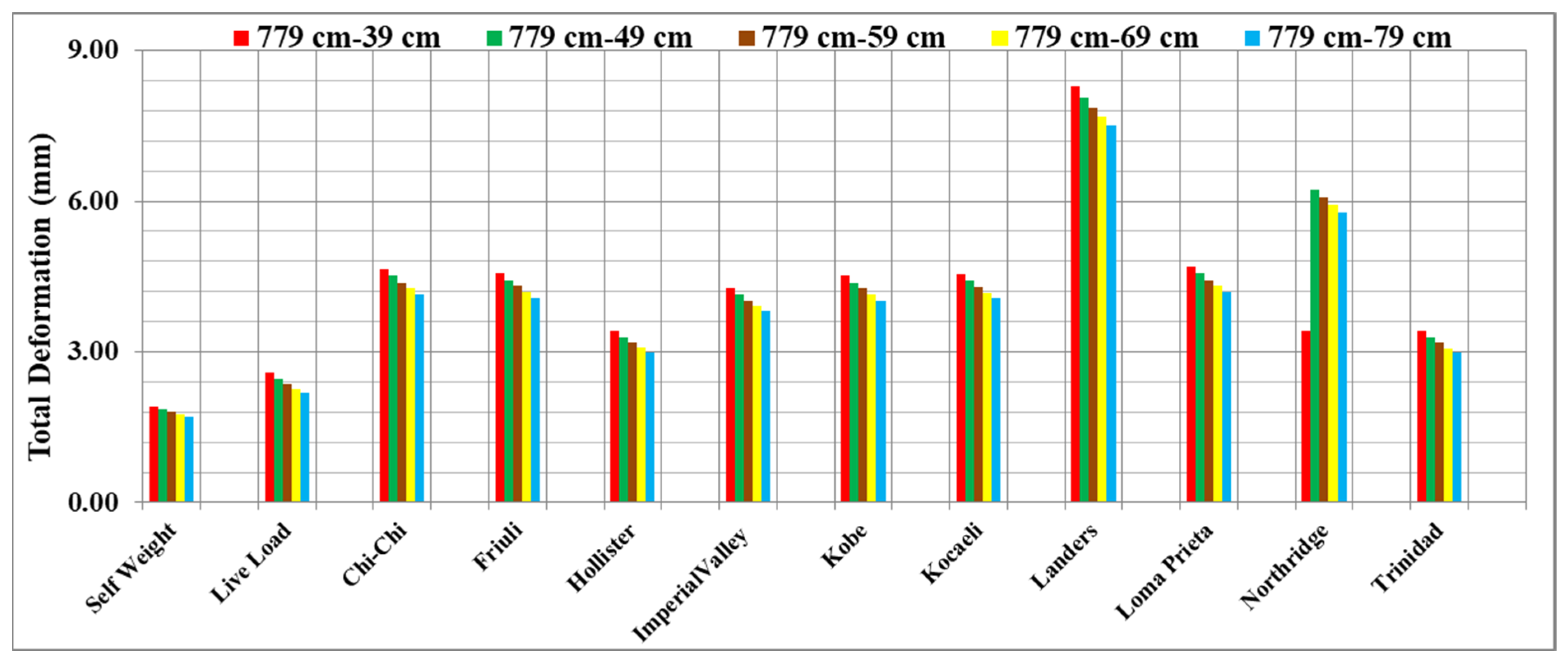
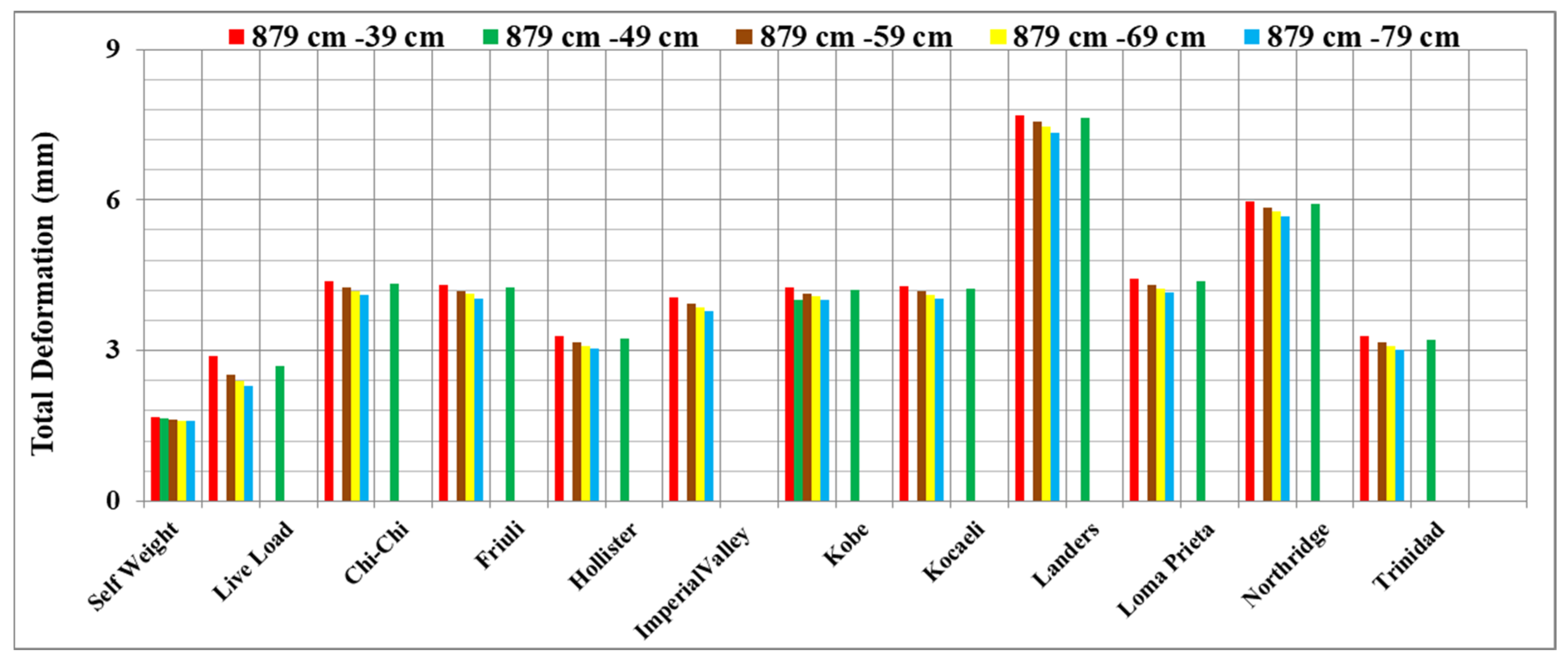
Masonry structures have a wide range of materials, but the most commonly used materials are stone and brick. It is not possible to determine the strength properties of masonry structures by testing their materials in the laboratory. Therefore, it is difficult to know the mechanical properties of the materials used in masonry building elements. Material properties affect the structural performance of masonry structures. The implementation of the Concrete Damage Plasticity (CDP) model is used for the purpose of simulating the nonlinear behavior shown by the wall. Masonry structures have high compressive strength. It is also considered as a brittle material with low tensile strength. Destructive methods are used to determine the material properties of historical buildings. However, this method is not preferred due to the importance of historical buildings [30,31]. Boundary conditions for all supports of the bridge and both sidewalls are defined by constant translational and rotational degrees of freedom. The boundary conditions for the supports and sidewalls of the single-span İscehisar Bridge were established by imposing constraints on translational and rotational degrees of freedom. It was defined in the model’s Modulus of Elasticity as 3.0 × 10⁹, 1.5 × 10⁹, and 2.5 × 10⁹ N/m2 for stone arches, timber block, and side walls, respectively. In addition, the density values assigned to stone arches, timber blocks, and side walls were 0.25, 0.05, and 0.20, respectively. Then, the Poisson’s Ratio was defined as 1600, 1300 and 1400 kg/m3 for stone arches, timber blocks, and side walls [32].

4. Ground Motions

In this study, 10 earthquake accelerations were tested on the İscehisar Bridge. The earthquake acceleration records used in the study were taken from the Pacific Earthquake Engineering Research Center (PEER) database [33,34]. The Rayleigh damping ratio was accepted as 5% in the analysis. It aimed to compare the effect of arch elements of historical stone bridges on dynamic response and earthquake damage. The earthquake acceleration was applied in the direction perpendicular to the tempan wall, where the geometrically weakest strength of the bridge model would be, as used in similar academic studies [24,25,35,36]. The earthquake records applied to the bridge are offered in Table 2.

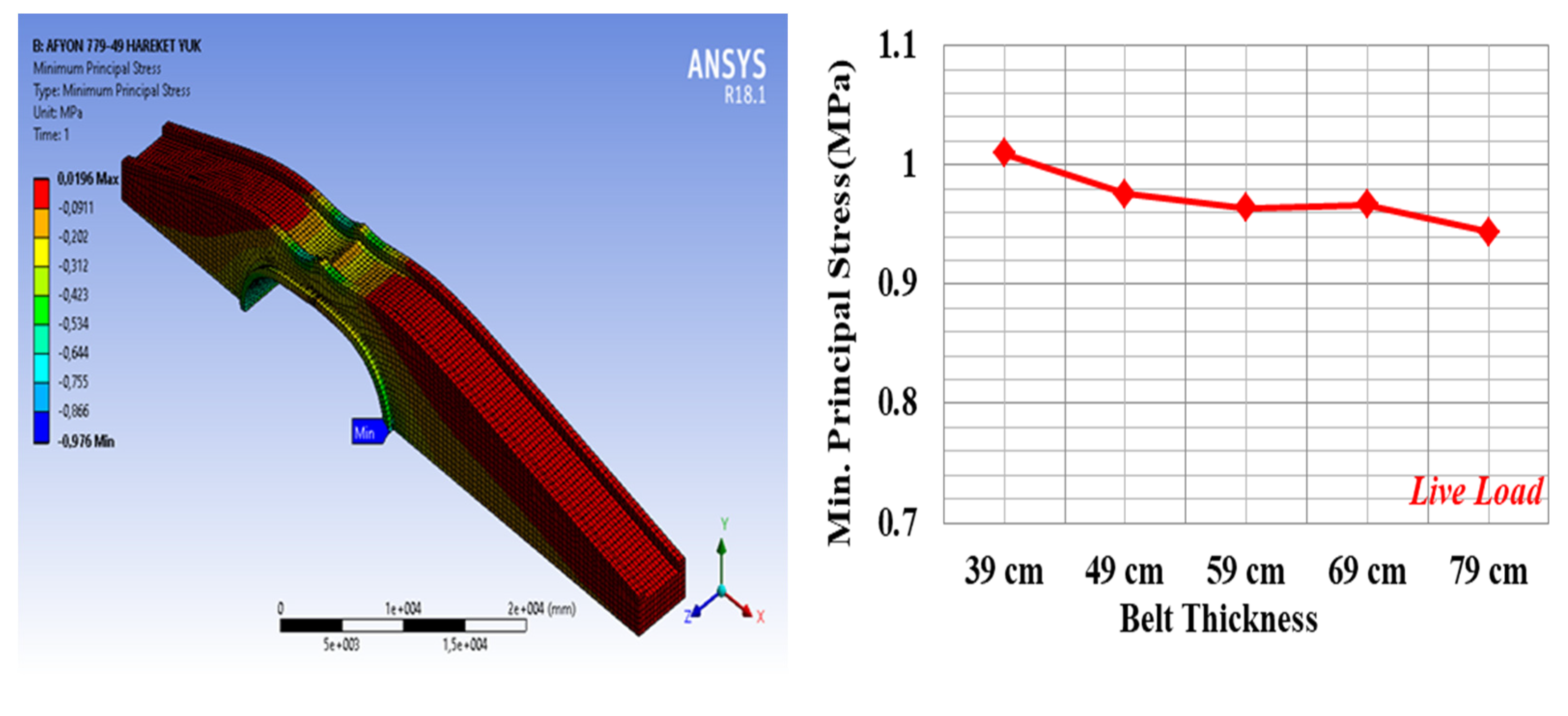
5. Live Load Analysis

To examine the behavior of the bridge under live load, live load loading was performed. The vehicle suitable for the H30-S24 vehicle class is loaded on the bridge according to certain assumptions. This heavy-duty truck, defined according to Turkish conditions, is approximately 1.5 times heavier than the HL-93 truck load given in AASHTO-LRFD. H30-S24 vehicle load and pedestrian load were used as live load. The H30-S24 vehicle load consists of the front axle weighing 60 kN, the 240 kN center axle 4.25 m from the front axle, and the 240 kN rear axle with distances ranging from 4.25 m to 9.0 m to the center axle. Pedestrian load on the border was taken as 3.6 kN/m2 [37,38]. The Iscehisar Bridge is 59.4 m long and 5.30 m wide. Since the width of the bridge was not suitable for double lanes, the vehicle was placed in a single lane. The H30-S24 truckload shown in Figure 3 is applied to the bridge as a live load.

6. Results

According to the research conducted, modal parameters and the changes that they undergo over time may serve as characteristics and indicators of the development and progression of damage [39,40]. To determine the structural behavior of the historical İscehisar Bridge, taking into account the different arch characteristics, the bridge’s own weight, the amount of deformation and displacement under the effect of live load, and sample earthquake accelerations, the maximum–minimum principal stress values of the bridge were analyzed using the FEM of the bridge. The obtained results were presented as visuals and comparative graphics. For the examination made by exchanging the belt height, the height was chosen as 779 cm and 879 cm. For each belt height, the arch thickness was selected as 39 cm, 49 cm, 59 cm, 69 cm, and 79 cm, separately. It aimed to examine the behavior of the bridge under static and dynamic effects as a result of the linear analyses carried out for the arch height and arch thickness conditions mentioned above. In the last part of the study, as a result of the linear analysis, nonlinear analysis was applied for the bridge model with a high max. deformation value in the bridge analysis. Then, linear and nonlinear results for this bridge model are compared. Before the dynamic investigation, the static investigations in Figure 4, Figure 5, Figure 6, Figure 7, Figure 8 and Figure 9 evaluated the effects of self-weight, moveable load, and vehicle loads. Furthermore, comparative graphics of the arch form of the bridge under its own weight were presented in Figure 4, Figure 5, Figure 6, Figure 7, Figure 8 and Figure 9. In the analysis applied under gravity on the historical İscehisar Bridge, whose arch height was chosen as 879 cm and 779 cm, displacement occurs in the arch opening. As the belt height decreases, the displacement increases. As the arch thickness decreases, the displacement increases. Furthermore, the tensile stress of the bridge increases as the arch thickness and arch height decrease under the weight of the bridge. As the belt height decreases, the compressive strength increases. There is an inverse relationship between the increase in arch thickness and the reduction in compressive strength. With the obtained stress increased up to 1.90 MPa, it can be anticipated that the historical one-span Iscehisar Bridge will not be destroyed, if it is stable and unharmed by earth gravity. It may be accepted that these obtained results were stable with the carrying/pressure resistance amounts (1/20–1/10) recommended by Pela et al. [5] for masonry structures which may be used as a mechanism in evaluating the destruction potential. As a result, as indicated above, in this stage of the research, the ratio of traction resistance to pressure resistance was determined to be 1/20 or 5%. However, no evidence of destructive potential was discovered. Thus, it was anticipated that the representation stress values less than 1/20 or 5% may not be focused by way of destroying the constructional strength.
The displacement and stress values of the bridge under its own weight and under the effect of live load were also obtained from the analysis. In the analyses applied under gravity and live load, the displacement in the historical İscehisar Bridge, for which the arch height was chosen as 879 cm and 779 cm, occurs in the arch opening. As the belt height decreases, the displacement decreases. As the arch thickness decreases, the displacement increases.
The max. principal tensile and compressive stresses that emerged as a result of the earthquake analyses applied to the bridge were examined. The max. principal strain is offered for the brittle crack of materials as also offered using St.Venant’s model. As stated by St.Venant’s model, the restraining state of the source is managed while the max. tensile strain method, εmax = ε1, with an exact constant limit value equivalent to the dependable pressure, ε0, at rupture. This relationship is supposed as follows:
ε 1 = 1 E σ 1 γ σ 2 + σ 3 = ε 0
To attain a safe proposal, the max. principal strain must be lesser than the allowable strain as follows:
  ε m a x = ε 1 = 1 E σ 1 γ σ 2 + σ 3 y i e l d i n g   s t r a i n f a c t o r   o f   s a f e t y = σ y E . n
The İscehisar Bridge, which spans a single distance, was also included in the max. distortional strain energy density model. The equation that represents the total strain energy for the triaxial situation is as follows:
T o t a l   S t r a i n   E n e r g y   p e r   u n i t   v o l u m e = 1 2 σ 1 ε 1 + 1 2 σ 2 ε 2 + 1 2 σ 3 ε 3
where,
ε 1 = 1 E σ 1 γ σ 2 + σ 3
ε 2 = 1 E σ 2 γ σ 1 + σ 3
  ε 3 = 1 E σ 3 γ σ 1 + σ 2
As a result, the last calculation for energy is expected by
S t r a i n   E n e r g y   D e n s i t y = 1 2 E σ 1 2 + σ 2 2 + σ 3 2 2 . γ σ 1 σ 2 + σ 2 σ 3 + σ 1 σ 3
In the analysis applied under gravity and live load, the tensile stress in the historical İscehisar Bridge, which has an arch height of 779 cm, occurs in the tempan wall. Tensile stress in the İscehisar Bridge with a belt height of 879 cm was generally formed in the tempan wall, only in the arch opening in the bridge analysis with an arch thickness of 39 cm. Assuming that the tensile strength of the masonry stone is 1 MPa, the tensile stresses were obtained from the analysis of the historical İscehisar Bridge under gravity and live load. Since the masonry stone is considerably lower than the tensile strength, no damage is expected on the bridge due to tensile stress. On the other hand, compressive stress occurred where the arch legs were supported on the ground. Assuming the compressive strength of the masonry stone is 20 MPa, and since the compressive stresses obtained in these regions were lower than the compressive strength of the material used, no damage was observed. As the belt height decreased, the compressive strength increased. As the arch thickness increased, the compressive strength decreased. Additionally, comparative graphics of the arch form of the bridge under its own weight and live load were presented in Figure 10, Figure 11, Figure 12, Figure 13, Figure 14 and Figure 15.
In the analysis applied under gravity, live load, and earthquake acceleration. In the İscehisar Bridge with arch heights of 879 cm and 779 cm, compressive stress occurs where the arch legs are supported on the ground. The max. compressive stress was obtained at around 5 MPa. Since the compressive stresses obtained from the analysis of the İscehisar Bridge under gravity, live load, and earthquake acceleration were considerably lower than the compressive strength of the masonry stone, assuming the compressive strength of the masonry stone was 20 MPa, no damage to the bridge due to pressure stress was expected as presented in Figure 16, Figure 17, Figure 18 and Figure 19.

7. Conclusions

The study carried out within the scope of this thesis investigated the effects of the arch element on the static and dynamic performance of historical bridges. For this aim, the historical İscehisar Bridge was elected as an instance. The displacements, tensile stresses, and compressive stresses obtained as a result of changing the height of the belt were evaluated by comparing them with the graphics:
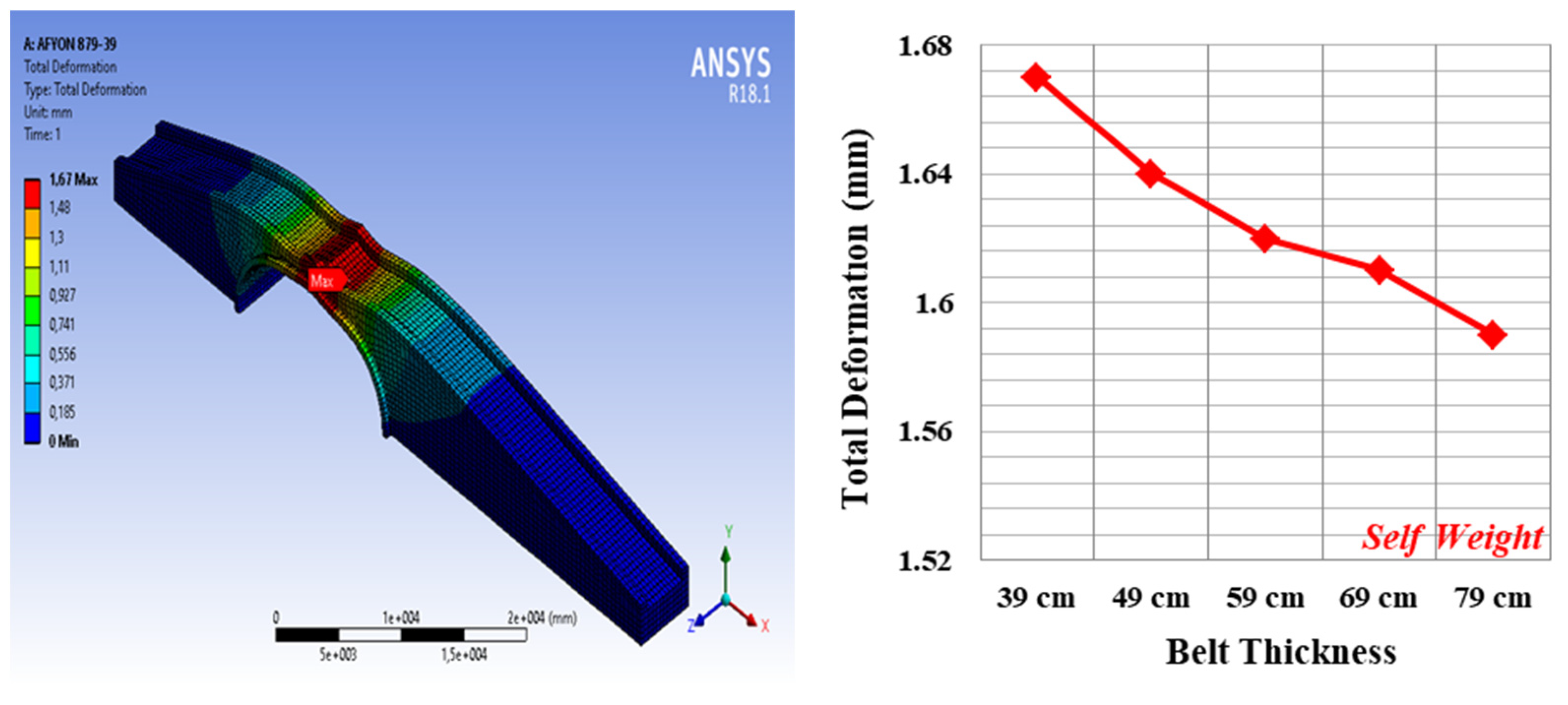
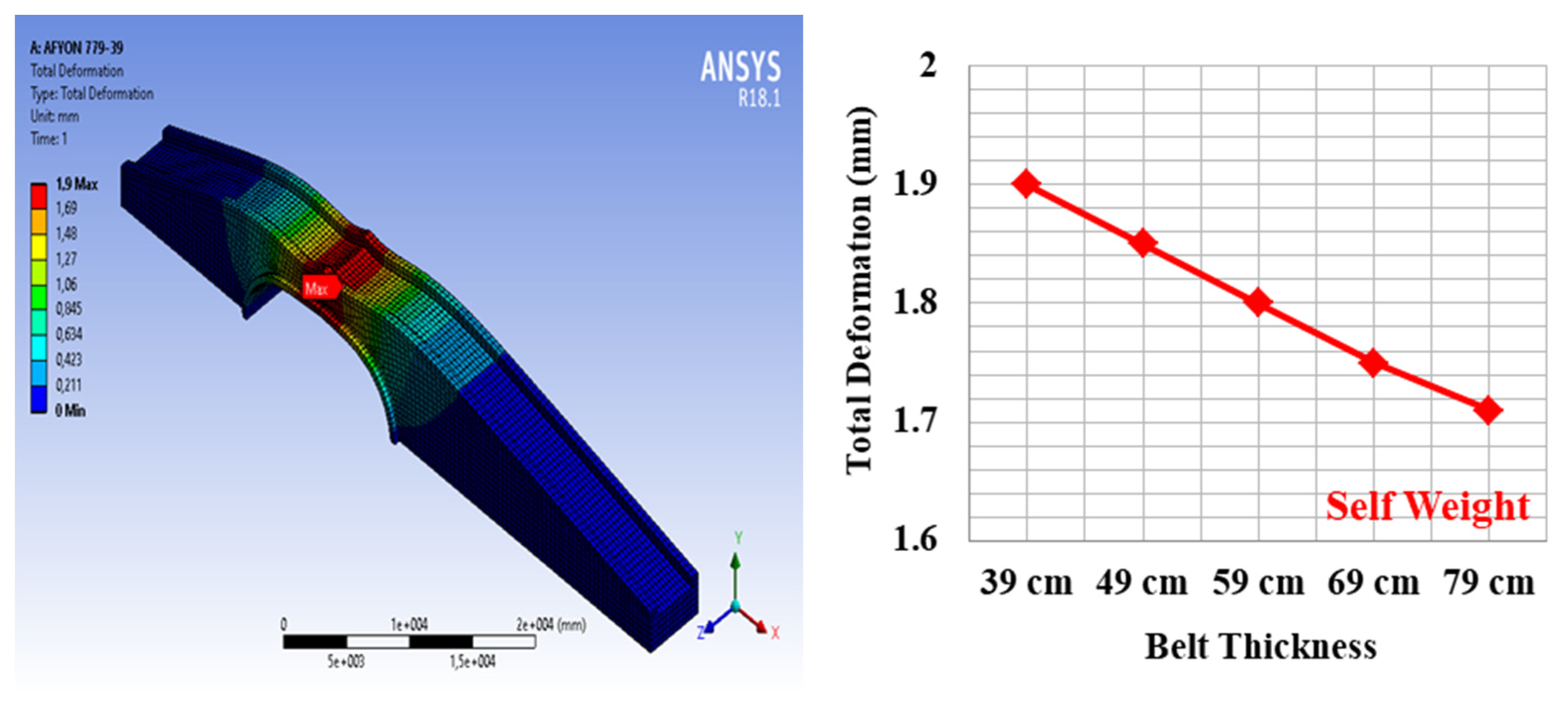
  • It was observed that the displacements increased as the arch height decreased under the bridge’s own weight. Max. displacements occurred at the arch opening;
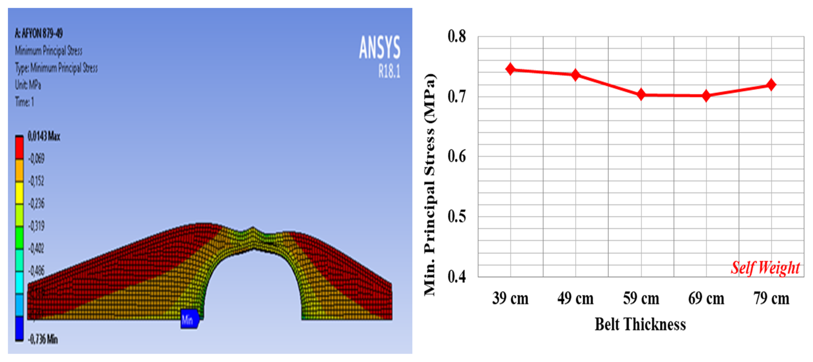
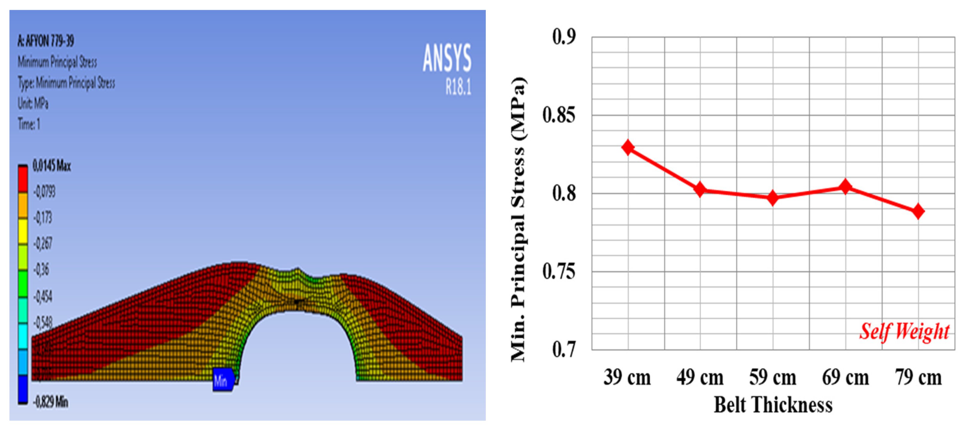
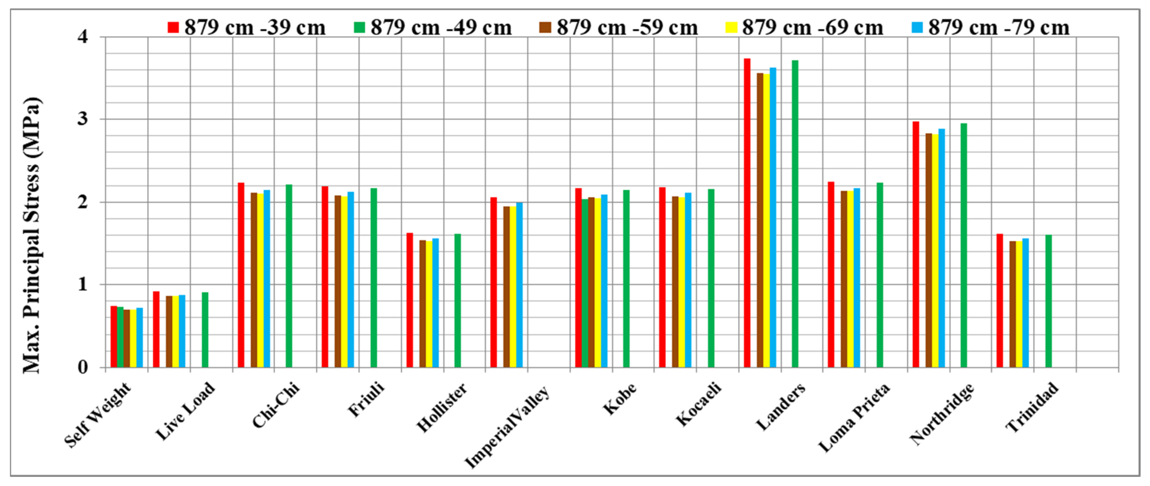
  • As the arch height of the bridge decreased, the tensile stress on the bridge increased. Tensile stresses occurred in the tempan wall in the analyses with a belt height of 879 cm and in the balustrade in the analyses with a belt height of 779 cm. As the belt height decreased, the compressive stress increased;
  • Compressive stresses were formed in the regions where the arch foot was supported on the ground. The displacement, tensile stress, and compressive stress increased curves with the decrease in arch height of the bridge under its own weight;
  • When the compressive stress values obtained as a result of the earthquake analyses applied to the bridge were examined, it was observed that the min. compressive strength of the bridge material, 20 MPa, was not exceeded. For this reason, no damage due to the pressure stress value was observed in the earthquake analyses applied to the bridge;
  • When the max. principal tensile stresses resulting from the earthquake analyses applied to the bridge were examined, it was detected that the tensile stress of the bridge material, 1 MPa, exceeds the tensile stress value in two earthquake accelerations for ten different earthquake accelerations examined;
  • Tensile stress values showed risk for Landers and Northridge earthquakes in the analyses. These two earthquake accelerations may pose a risk of damage to the bridge. Potential damage areas for the Landers and Northridge earthquakes were expected to occur in areas where the pier is supported on the ground.

Author Contributions

Methodology, M.K.; Software, G.Ç.; Formal analysis, M.K.; Investigation, M.K.; Data curation, M.K. and G.Ç.; Writing—review & editing, M.K. All authors have read and agreed to the published version of the manuscript.

Funding

This research received no external funding.

Institutional Review Board Statement

Not applicable.

Informed Consent Statement

Not applicable.

Data Availability Statement

All data presented in this paper.

Conflicts of Interest

The authors declare no conflict of interest.

References

  1. Hasol, D. Ansiklopedik Mimarlık Sözlüğü, 2nd ed.; Sıralar Matbaası: İstanbul, Turkey, 1979; p. 560. [Google Scholar]
  2. Available online: http://www.silvan.gov.tr/malabadi-koprusu (accessed on 19 December 2022).
  3. Drosopoulos, G.; Stavroulakis, G.; Massalas, C. Influence of the geometry and the abutments movement on the collapse of stone arch bridges. Constr. Build. Mater. 2008, 22, 200–210. [Google Scholar] [CrossRef]
  4. Beyer, L. Arched Bridges. Master’s Thesis, University of New Hampshire, Durham, UK, 2012; p. 78. [Google Scholar]
  5. Pelà, L.; Aprile, A.; Benedetti, A. Seismic assessment of masonry arch bridges. Eng. Struct. 2009, 31, 1777–1788. [Google Scholar] [CrossRef]
  6. Wu, L. Serviceability Assessments of Masonry Arch Bridges. Ph.D. Thesis, Cardiff University, Cardiff, Wales, 2010; p. 248. [Google Scholar]
  7. Zhang, Y. Advanced Nonlınear Analysıs of Masonry Arch Brıdges. Ph.D. Thesis, Imperial College Londra, London, UK, 2015; p. 293. [Google Scholar]
  8. Yılmaz, B. Tarihi Köprülerin Yapısal Davranışına Kemer Geometrisinin Etkisi. Master’s Thesis, Karadeniz Teknik Üniversitesi, Trabzon, Turkey, 2016; p. 63. [Google Scholar]
  9. Ahmad, S.H.S. Static Analysis of Masonry Arches. Ph.D. Thesis, University of Salford, Salford, UK, 2017; p. 155. [Google Scholar]
  10. Özmen, A.; Sayın, E. Linear Dynamic analysis of a masonry arch bridge. In Proceedings of the International Conference on Innovative Engineering Applications (CIEA’ 2018), Sivas, Turkey, 20–22 September 2018; pp. 1–7. [Google Scholar]
  11. Gönen, S. Relıabılıty- Based Seısmıc Assessment of Masonry Arch Brıdges. Ph.D. Thesis, Boğaziçi University, İstanbul, Turkey, 2020; p. 217. [Google Scholar]
  12. Akın, K. Tarihi Yığma Köprülerin Farklı Sönüm Oranları Altında Sismik Tepkisinin Değerlendirilmesi. Master’s Thesis, Fırat Üniversitesi, Elazığ, Turkey, 2020; p. 72. [Google Scholar]
  13. Rahimi, A.; Aval, S.B.B.; Noori, M.; Sarhosis, V.; Wu, Z.; Nikkhoo, A.; Altabey, W.A. A simplified beam model for the numerical analysis of masonry arch bridges—A case study of the Veresk railway bridge. Structures 2022, 45, 1253–1266. [Google Scholar] [CrossRef]
  14. Addessi, D.; Gatta, C.; Nocera, M.; Liberatore, D. Nonlinear Dynamic Analysis of a Masonry Arch Bridge Accounting for Damage Evolution. Geosciences 2021, 11, 343. [Google Scholar] [CrossRef]
  15. Yilmaz, E.G.; Sayin, E.; Özmen, A. Dynamic Analysis of Historical Masonry Arch Bridges under Different Earthquakes: The Case of Murat Bey Bridge. Turk. J. Sci. Technol. 2022, 17, 461–473. [Google Scholar] [CrossRef]
  16. Bozyigit, B.; Acikgoz, S. Dynamic amplification in masonry arch railway bridges. Structures 2022, 45, 1717–1728. [Google Scholar] [CrossRef]
  17. Sakcalı, G.B.; Gönül, A.; Bağbancı, M.B.; Yüksel, I. Linear/Nonlinear Dynamic Analysis and Prediction of Failure Mechanism of Irgandi Bridge. Period. Polytech. Civ. Eng. 2022, 66, 1248–1261. [Google Scholar] [CrossRef]
  18. Özodabaş, A.; Artan, C. Determination of Stress and Deformation Zones of Historical Mus Murat Bridge. Bilecik Şeyh Edebali Üniversitesi Fen Bilim. Derg. 2021, 8, 413–429. [Google Scholar] [CrossRef]
  19. Nemutlu, F.; Güzel, I.; Balun, B.; Öztürk, M.; Sari, A. Nonlinear Seismic Assessment of Historical Masonry Karaz Bridge Under Different Ground Motion Records. Bitlis Eren Üniversitesi Fen Bilim. Derg. 2023, 12, 247–260. [Google Scholar] [CrossRef]
  20. Zampieri, P.; Santinon, D.; Piazzon, R.; Hofer, L.; Toska, K.; Faleschini, F.; Pellegrino, C.; Ricci, D.; Iodice, F.; Vecchi, A.; et al. Intrados CFRCM strengthening of masonry arches. Procedia Struct. Integr. 2023, 44, 926–933. [Google Scholar] [CrossRef]
  21. Aktürk, K.K. Afyonkarahisar Bölgesi Tarihi Taş Köprülerinin Mimari ve Statik Özellikleri. Master’s Thesis, Afyon Kocatepe Üniversitesi, Afyonkarahisar, Turkey, 2019; p. 147. [Google Scholar]
  22. Available online: https://www.google.com/maps/@39.4329458,33.6926132,804307m/data=!3m1!1e3?entryttu (accessed on 1 June 2020).
  23. ANSYS. 1998. Available online: https://www.ansys.com/ (accessed on 1 June 2020).
  24. Karalar, M.; Yeşil, M. Effect of near-fault earthquakes on a historical masonry arch bridge (KonjicBridge). Earthq. Struct. 2021, 21, 125–136. [Google Scholar] [CrossRef]
  25. Karalar, M.; Yeşil, M. Structural Investigation of a Historical Masonry Arch Bridge under Far-Fault Earthquakes. Teh. Vjesn.—Tech. Gaz. 2023, 30, 1443–1450. [Google Scholar] [CrossRef]
  26. Jebur, A.K.; Khan, I.; Nath, Y. Numerical and Experimental Dynamic Contact of Rotating Spur Gear. Mod. Appl. Sci. 2011, 5, 254. [Google Scholar] [CrossRef]
  27. Kadhim, M.M.A. Factors effect on the effective length in a double strap joint between steel plates and CFRP. Int. J. Adv. Appl. Sci. 2012, 1, 11–18. [Google Scholar]
  28. Makris, N.; Chang, S. Effect of Damping Mechanisms on the Response of Seismically Isolated Structures; PEER-98/06; Pacific Earthquake Engineering Research Center: Berkeley, CA, USA, 1998. [Google Scholar]
  29. Makris, N.; Black, C.J. Evaluation of Peak Ground Velocity as a “Good” Intensity Measure for Near-Source Ground Motions. J. Eng. Mech. 2004, 130, 1032–1044. [Google Scholar] [CrossRef]
  30. Ünay, A.İ. A Method for the Evaluation of the Ultimate Safety of Historical Masonry Tructures. Doctoral Thesis, Ortadoğu Teknik Üniversitesi, Ankara, Turkey, 1997; p. 261. [Google Scholar]
  31. Kazaz, I.; Kocaman, I. Taş yığma camilerin sismik yük kapasitelerinin değerlendirilmesi. Gazi Üniversitesi Mühendislik Mimar. Fakültesi Derg. 2018, 2018, 557–574. [Google Scholar] [CrossRef]
  32. Sevim, B.; Bayraktar, A.; Altunişik, A.C.; Atamtürktür, S.; Birinci, F. Assessment of nonlinear seismic performance of a restored historical arch bridge using ambient vibrations. Nonlinear Dyn. 2010, 63, 755–770. [Google Scholar] [CrossRef]
  33. PEER. NGA-East: Adjustments to Median Ground-Motion Models for Central and Eastern North America (PEER Report No. 2015/08); Pacific Earthquake Engineering Research Center, University of California: Berkeley, CA, USA, 2015. [Google Scholar]
  34. PEER. NGA-East: Median Ground-Motion Models for the Central and Eastern North America Region (PEER Report No. 2015/04); Pacific Earthquake Engineering Research Center, University of California: Berkeley, CA, USA, 2015. [Google Scholar]
  35. Özmen, A. Yakın Ve Uzak Fay Hareketlerine Maruz Tarihi Yığma Bir Köprünün Sismik Performansının Değerlendirilmesi. Master’s Thesis, Fırat Üniversitesi, Elazığ, Turkey, 2019; p. 63. [Google Scholar]
  36. Karalar, M.; Yeşil, M. Implications of Arch Warp Altitudes on an Ancient Masonry Bridge under Ground Movements. Appl. Sci. 2023, 13, 7395. [Google Scholar] [CrossRef]
  37. Uluğ, N.İ. Öngerilmeli Bir Köprü Tasarımı ve Performans Değerlendirilmesi. Master’s Thesis, İstanbul Teknik Üniversitesi, İstanbul, Turkey, 2008; p. 88. [Google Scholar]
  38. Çakır, B.B. Lıve Load Relıabılıty Index Evaluatıon for Post Tensıoned Balanced Cantılever Brıdges. Master’s Thesis, Ortadoğu Teknik Üniversitesi, Ankara, Turkey, 2015; p. 166. [Google Scholar]
  39. Civera, M.; Mugnaini, V.; Fragonara, L.Z. Machine learning-based automatic operational modal analysis: A structural health monitoring application to masonry arch bridges. Struct. Control. Health Monit. 2022, 29, e3028. [Google Scholar] [CrossRef]
  40. Civera, M.; Calamai, G.; Zanotti Fragonara, L. System identification via Fast Relaxed Vector Fitting for the Structural Health Monitoring of masonry bridges. Structures 2021, 30, 277–293. [Google Scholar] [CrossRef]
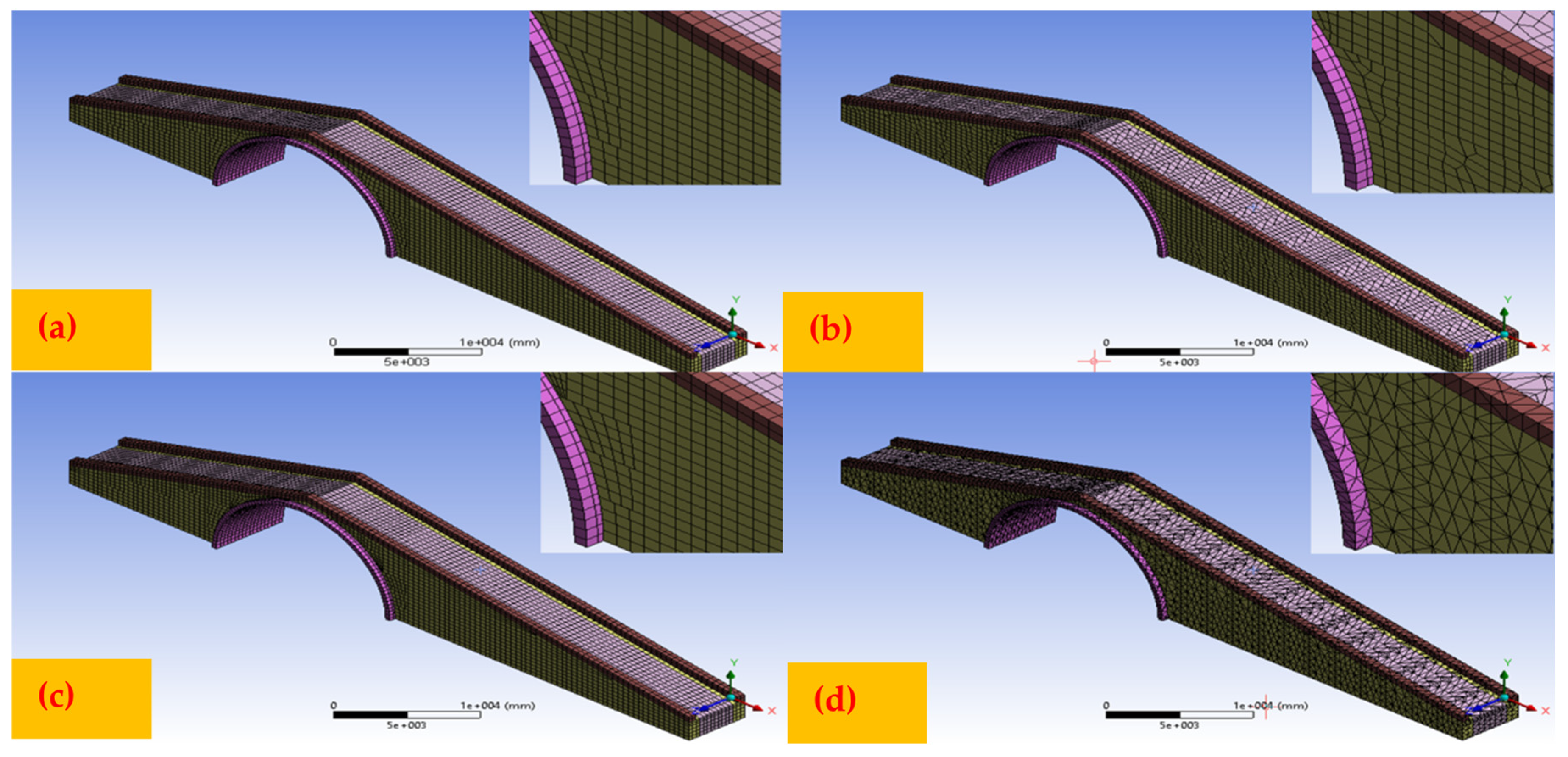
Figure 1. Elements forming the arch geometry.
Applsci 13 10740 g001
Figure 2. Mesh selections, (a) Automatic, (b) HexDominant, (c) Multizone, (d) Tetrahedrons method.
Applsci 13 10740 g002
Figure 3. Analysis of the bridge under the influence of its own weight, live load, and earthquake acceleration.
Applsci 13 10740 g003
Figure 4. Deformation of the bridge under the influence of its own weight for arch thickness 879 cm.
Applsci 13 10740 g004
Figure 5. Deformation of the bridge under the influence of its own weight for arch thickness 779 cm.
Applsci 13 10740 g005
Figure 6. Tensile stress of the bridge under its own weight for arch thickness 879 cm.
Applsci 13 10740 g006
Figure 7. Tensile stress of the bridge under its own weight for arch thickness 779 cm.
Applsci 13 10740 g007
Figure 8. Compressive stress of the bridge under its own weight for arch thickness 879 cm.
Applsci 13 10740 g008
Figure 9. Compressive stress of the bridge under its own weight for arch thickness 779 cm.
Applsci 13 10740 g009
Figure 10. Deformation of the bridge under live load for arch thickness 879 cm.
Applsci 13 10740 g010
Figure 11. Deformation of the bridge under live load for arch thickness 779 cm.
Applsci 13 10740 g011
Figure 12. Tensile stress of the bridge under live load for arch thickness 879 cm.
Applsci 13 10740 g012
Figure 13. Tensile stress of the bridge under live load for arch thickness 779 cm.
Applsci 13 10740 g013
Figure 14. Compression stress of the bridge under live load for arch thickness 879 cm.
Applsci 13 10740 g014
Figure 15. Compression stress of the bridge under live load for arch thickness 779 cm.
Applsci 13 10740 g015
Figure 16. Total deformation analysis results of İscehisar Bridge arch height 779 cm and different arch thickness under dead load, live load and ground motions.
Applsci 13 10740 g016
Figure 17. Max. Principal Stress of İscehisar Bridge arch height 779 cm and different arch thickness under dead load, live load and ground motions.
Applsci 13 10740 g017
Figure 18. Total deformation analysis results of İscehisar Bridge arch height 879 cm and different arch thickness under dead Load, live load and ground motions.
Applsci 13 10740 g018
Figure 19. Max. Principal Stress of the İscehisar Bridge arch height 879 cm and different arch thickness under Dead Load, Live load, and ground motions.
Applsci 13 10740 g019
Table 1. Mesh methods applied to the bridge and number of elements—points.
İscehisar
(Belt Height-Arch Thickness)
Automatic MethodHexDominant MethodMultizone MethodTetrahedrons Method
İscehisar
(879 cm–79 cm)
Nodes150,906155,176161,029116,767
Elements20,94229,58822,68146,565
İscehisar
(879 cm–69 cm)
Nodes151,308153,363160,783115,745
Elements20,96629,87122,64546,043
İscehisar
(879 cm–59 cm)
Nodes151,308152,411160,783116,204
Elements20,99628,95722,64546,334
İscehisar
(879 cm–49 cm)
Nodes143,244144,202152,563112,705
Elements19,70027,53821,33144,843
İscehisar
(879 cm–39 cm)
Nodes143,172144,770152,827111,985
Elements19,66427,13421,34944,156
İscehisar
(779 cm–79 cm)
Nodes159,299158,501167,283118,616
Elements22,28231,03323,68347,326
İscehisar
(779 cm–69 cm)
Nodes159,149159,019167,208119,457
Elements22,25231,42023,66847,814
İscehisar
(779 cm–59 cm)
Nodes159,971160,565167,775120,596
Elements22,39031,70223,75548,322
İscehisar
(779 cm–49 cm)
Nodes152,489152,800159,987116,880
Elements21,18430,24922,50146,625
İscehisar
(779 cm–39 cm)
Nodes151,997150,210159,906115,122
Elements21,11228,82122,49846,625
Table 2. Earthquake records (PEER) used in the analysis.
EarthquakeStationMagnitude (Mw)Depth (km)PGA
(g)
PGV
(cm/s)
PGD
(cm)
PGV/
PGA (cm)
Chi-Chi, 1999TCU0457.6280.36121.54821.8830.061
Friuli, 1976Tolmezzo
(000)
6.505.10.35122.0204.0670.064
Hollister, 1961Hollister City
Hall
5.607.40.19512.3554.3000.065
İmperial Valley, 1979El Centro
Array#2
6.539.960.31531.49614.1260.102
Kobe, 1995Kakogawa6.9017.90.34527.6789.6940.082
Kocaeli 1999Yarımca7.51160.34962.18251.3020.182
Landers, 1992Coolwater7.2870.78031.59816.5010.041
Loma Prieta, 1989Gilroy Array
#3
6.9317.480.36744.69519.6150.124
Northridge, 1994Castaic-Old
Ridge Route
6.6917.50.56851.8279.0350.093
Trinidad, 1983Rio Dell
Overpass
7.2015.10.1948.4640.8880.045
Disclaimer/Publisher’s Note: The statements, opinions and data contained in all publications are solely those of the individual author(s) and contributor(s) and not of MDPI and/or the editor(s). MDPI and/or the editor(s) disclaim responsibility for any injury to people or property resulting from any ideas, methods, instructions or products referred to in the content.

