Article

Wave Polarization Control in Anisotropic Locally Resonant Materials

1
Department of Civil and Environmental Engineering, Politecnico di Milano, Piazza Leonardo da Vinci 32, 20133 Milan, Italy
2
Institut Jean Le Rond d’Alembert, Sorbonne Universités, CNRS, UMR 7190, F-75005 Paris, France
*
Author to whom correspondence should be addressed.
Appl. Sci. 2023, 13(19), 10797; https://doi.org/10.3390/app131910797
Submission received: 28 August 2023 / Revised: 14 September 2023 / Accepted: 18 September 2023 / Published: 28 September 2023
(This article belongs to the Section Materials Science and Engineering)

Abstract

:
Elastic wave propagation in solids can be controlled and manipulated by properly designed metamaterials. In particular, polarization conversion can be obtained by using anisotropic materials. In this paper, we propose a three-component locally resonant material with non-symmetrically coated inclusions, and we study the effect of the anisotropic equivalent mass on band gap formation and the polarization conversion of elastic waves. The equivalent frequency-dependent mass tensor is obtained through the two-scale homogenization approach. The study of the eigenvalues of the mass tensor enables to predict band gaps and polarization bands, as well as identifying a priori the effect of different geometric and material parameters, thus opening the way to metamaterial optimization.

1. Introduction

Locally resonant metamaterials have attracted a deep interest in recent years for their peculiar properties concerning wave propagation. In particular, periodic materials with heavy, stiff inclusions with a soft coating embedded in a stiff matrix have been demonstrated to have broad spectral gaps at low frequency, see, for example [1,2]. The intervals of frequency inside which waves are attenuated can have different applications in vibration isolation and impact absorption [3,4,5,6,7,8].
The physical mechanism of local resonance with the corresponding spectral gaps can be associated with the concept of an “effective dynamic mass density” that becomes negative in certain frequency intervals [9,10]. Asymptotic homogenization is a mathematical technique widely employed to study the effective homogenized properties of periodic metamaterials [11,12,13,14]. Under proper hypotheses on the constituent materials, the method was employed in [15] to study the propagation of elastic waves in binary locally resonant metamaterials with cylindrical soft inclusions periodically distributed in a stiff matrix. In the range of validity of the homogenization, the authors also proved that the intervals of negative effective mass density correspond to the band gaps of the metamaterial. The same approach was followed also to characterize the dynamics of ternary locally resonant metamaterials and plates [2,16].
The anisotropic properties of metamaterials can be exploited to achieve peculiar dispersive properties besides those related to the formation of band gaps. In [17], the authors studied wave propagation through a locally resonant metamaterial characterized by anisotropic dynamic mass density in the presence of an interface and derived the conditions leading to negative refraction. Another important aspect is the polarization of propagating waves, which depends on the anisotropic properties of materials. Non-isotropic locally resonant materials can be designed to achieve mode conversion, for instance, from longitudinal to shear waves or from longitudinal or flexural to torsional waves [18,19,20], for several interesting applications [21].
In this work, we make use of the asymptotic homogenization technique to study the in-plane propagation of elastic waves in a ternary locally resonant metamaterial made of a stiff matrix and cylindrical eccentric coated inclusions, which is characterized by an effective anisotropic mass. After presenting the main hypotheses concerning the geometry of the metamaterial and the stiffness contrast of the constituent materials, Section 2 is devoted to developing the homogenization procedure and obtaining the explicit expressions of the effective stiffness and mass tensors, which are both anisotropic. This allows to highlight the effect of the different material and geometric parameters and opens the way to metamaterial optimization.
The elastic wave propagation within the periodic media is then investigated in Section 3, where we show that the dispersion properties of the metamaterial depend on the signature of the effective mass. Particular emphasis is devoted to the case of an indefinite mass tensor, which leads to the formation of polarization bands that can be exploited for manipulating the polarization of elastic waves.
Finally, in Section 4, we perform several transmission analyses to validate the results predicted through asymptotic homogenization.

2. Materials and Methods

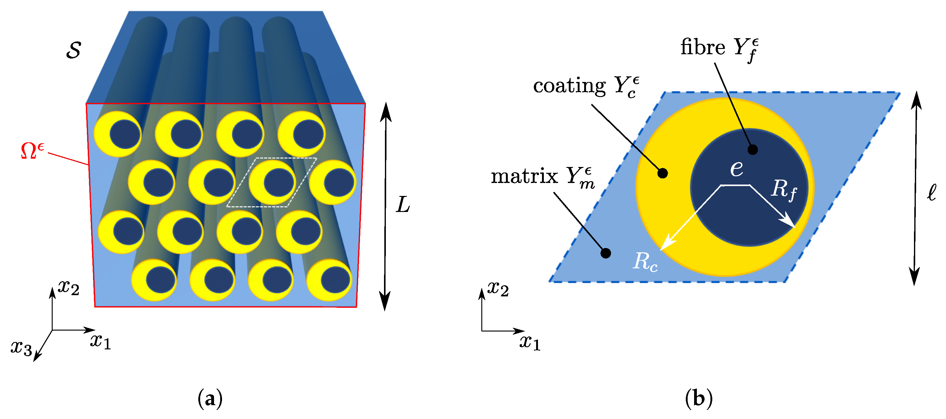
2.1. Problem Formulation

Let us consider a linear elastic solid S , endowed with two-dimensional periodicity, in the plane x 1 x 2 , composed by a matrix (m) with coated cylindrical inclusions (or fibers, f). The internal fiber has an eccentricity e with respect the external coating (c) as shown in Figure 1. The in-plane periodicity of the cylindrical body allows us to study the problem under plane strain conditions. For this purpose, let Ω ϵ be the section of S with the plane x 3 = 0 ; it can be obtained by the periodic repetition of the unit cell Y ϵ depicted in Figure 1b, and let x = x 1 e 1 + x 2 e 2 be the macroscopic in-plane position vector.
We assume the scale separation hypothesis, i.e., that ϵ = / L 1 , L and being the characteristic sizes of Ω ϵ and Y ϵ , respectively.
Under the small strain and displacement hypothesis, the in-plane wave propagation at a fixed angular frequency ω within Ω ϵ is governed by the Helmholtz equation:
· D ϵ : ε ( u ϵ ) + ρ ϵ ω 2 u ϵ = 0 in Ω ϵ ,
where u ( x ) = u 1 ( x ) e 1 + u 2 ( x ) e 2 is the displacement field, and ε ( ) is the symmetric part of the gradient of ( ) , while D ϵ ( x ) and ρ ϵ ( x ) are, respectively, the periodically varying fourth-order elastic stiffness tensor and mass density of the constituent materials. Considering constitutive isotropic materials, the elastic stiffness tensor can be expressed as
D ϵ = 2 μ ϵ I + λ ϵ I I ,
where λ ϵ ( x ) and μ ϵ ( x ) are the periodically varying Lame’s constants.
To obtain a local resonant mechanism, we consider the case of soft inclusions in a stiff matrix. In particular, we assume a high stiffness contrast between the matrix and the coating, whilst we prescribe the fibers, which play the role of resonant masses only, to be stiffer than the coating. The mass densities of the three materials are supposed to be of the same order of magnitude. These hypothesis are introduced in the model as follows:
λ ϵ = λ m in Y m ϵ ϵ 2 λ c in Y c ϵ ϵ 2 N λ f in Y f ϵ , μ ϵ = μ m in Y m ϵ ϵ 2 μ c in Y c ϵ ϵ 2 N μ f in Y f ϵ and ρ ϵ = ρ m in Y m ϵ ρ c in Y c ϵ ρ f in Y f ϵ
where λ m , λ c and λ f are of the same order of magnitude, as well as the triplets μ m , μ c , μ f and ρ m , ρ c , ρ f . The integer N 1 appearing as an exponent of the scaling parameter ϵ in the fiber stiffness (3) fixes the stiffness ratio between the fibers and matrix, but will not play any role in the further developments. If N 2 , the fibers are stiffer than the matrix, while if N = 1 , they are stiffer than the coating but softer than the matrix.

2.2. Asymptotic Homogenization

According to the two-scale asymptotic homogenization technique, we introduce the homogenized domain Ω and the fast variable y = x / ϵ = y 1 e 1 + y 2 e 2 , which lives in the re-scaled unit cell Y = Y ϵ / ϵ of the periodic media. Then, the solution of Equation (1) is searched in the following form:
u ϵ ( x ) = u 0 x , x ϵ + ϵ u 1 x , x ϵ + ϵ 2 u 2 x , x ϵ + o ( ϵ 2 ) in Ω ϵ ,
where the vector fields u i ( x , y ) are defined on Ω × Y and are Y —periodic with respect to the second variable.
Replacing the asymptotic expansion (4) in the governing Equation (1), one obtains a sequence of differential problems associated to each order of the paramater ϵ , which can be solved subsequently. Here, we briefly summarize the solution of the homogenization at the first order, i.e., the determination of the homogenized displacement field u 0 ( x , y ) .
Motion in the matrix—Restricting the focus on the matrix only, it is possible to prove (see [15] for further details) that the first term in the development (4) must be independent of the fast variable, namely,
u 0 ( x , y ) = U 0 ( x ) in Ω × Y m .
Then, the homogenization procedure allows to define the homogenized stiffness tensor D 0 of the periodic media, whose components can be evaluated through
D i j h k 0 = 1 | Y | Y m ε y ( χ i j ) + e i e j : D m : ε y ( χ h k ) + e h e k d y ,
for i , j , h , k { 1 , 2 } . In Equation (6), functions χ i j ( y ) represent the periodic displacement field in the matrix of the re-scaled unit cell Y subject to a uniform eigenstrain e i e j , to a periodic boundary condition on Y and to the free-traction boundary condition on the internal boundary Y m \ Y with the coating, i.e., χ i j ( y ) solves the matrix cell problems here below:
y · D m : ε y ( χ i j ) + e i e j = 0 in Y m χ i j periodic on Y D m : ε y ( χ i j ) + e i e j · n anti - periodic on Y D m : ε y ( χ i j ) + e i e j · n = 0 on Y m \ Y ,
where n is the outward normal at the boundary. Therefore, the effective stiffness tensor D 0 , defined by (6), can be interpreted as the homogenized stiffness of the holed periodic media. This result is a consequence of the assumed high stiffness contrast between the matrix and the inclusions. From Equation (6), it is clear that D 0 possesses minor and major symmetries, and it is possible to prove that it also satisfies the strong ellipticity condition:
α R + such that a , b one has a b : D 0 : a b α a 2 b 2 .
Motion in the inclusions—Without loss of generality, we assume that the origin of the reference system y 1 y 2 coincides with the center of the fiber. Independently of the specific value of N 1 in (3), it is possible to show that the fiber undergoes an in-plane rigid body motion within Y, i.e., one has
u 0 ( x , y ) = i = 1 2 U i 0 ( x ) τ i + ψ i y e 3 in Ω × Y f
where τ i and ψ i for i { 1 , 2 } describe, respectively, the displacement of the centroid and the in-plane rotation of the fiber. In the coating, the linearity of the problem allows to express the displacement field in the following form:
u 0 ( x , y ) = i = 1 2 U i 0 ( x ) η i ( y ) in Ω × Y c ,
where the functions η i , for i { 1 , 2 } , solve the differential problems:
y · D c : ε y ( η i ) + ρ c ω 2 η i = 0 in Y c η i = e i on Y c \ Y f η i = τ i + ψ i y e 3 on Y f .
The terms τ i and ψ i , which appear in the boundary conditions of (11), have to be determined by enforcing the balance of linear and angular momentum of the fiber, which read
Y f D c : ε y ( η i ) · n d y + ρ f | Y f | ω 2 τ i = 0 e 3 · Y f y D c : ε y ( η i ) · n d y + ρ f ω 2 I f ψ i = 0 for i , j { 1 , 2 } ,
I f being the polar moment of the fib and n the exterior normal to Y f . Equations (11) and (12) define the inclusion cell problem at a given frequency ω , whose solution is given by the fields η i ( y ) , τ i and ψ i . To underline the frequency dependence of the latter, we will write in the following η i ( y , ω ) , τ i ( ω ) and ψ i ( ω ) .
Homogenized equation of motion—Following the asymptotic homogenization procedure, one can retrieve the effective Helmholtz equation of the periodic media:
x · D 0 : ε x ( U 0 ) + ω 2 ρ 0 ( ω ) · U 0 = 0 in Ω ,
where we introduced the homogenized mass density tensor ρ 0 ( ω ) , which turns out to be frequency dependent. The components of the mass density tensor read
ρ i j 0 ( ω ) = ρ s t δ i j + ρ c | Y c | | Y | 1 | Y c | Y c η j i ( y , ω ) d y 1 + ρ f | Y f | | Y | ( τ j i ( ω ) 1 ) ,
where δ i j is Kronecker’s delta, and
ρ s t = ρ m | Y m | | Y | + ρ c | Y c | | Y | + ρ f | Y f | | Y | ,
is the static mass density of the periodic media. Note that, from Equation (14), the particular geometric shape of the matrix does not affect the definition of the effective dynamic mass of the media.

3. Results

The asymptotic homogenization procedure presented in Section 2 allows us to study the effective dynamic properties of locally resonant materials, under the assumed hypotheses, with arbitrary cell shape and inclusions. From now on, for the sake of simplicity, we consider the specific case depicted in Figure 2a of a square unit cell of side . The position of the inner inclusion, i.e., the fiber, with respect to the coating, is univocally determined by the eccentricity e between the two centers and the inclination angle ϑ [ 0 , 2 π ] of the line connecting the two centers, with respect to the horizontal direction.

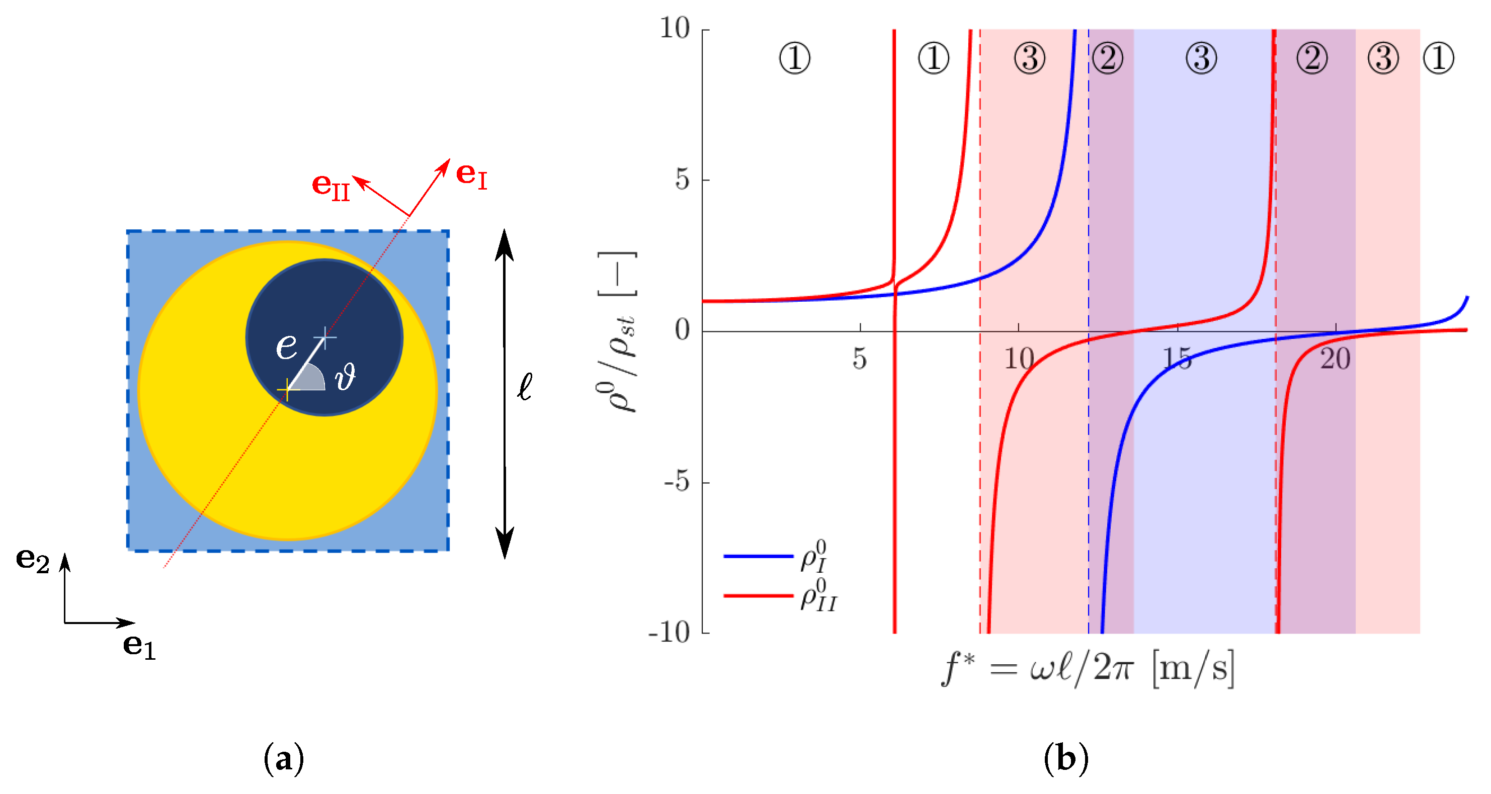
3.1. Anisotropic Effective Mass

Through (14), one can compute the components of the homogenized mass density tensor ρ 0 , which is symmetric and, in general, anisotropic. Due to the spectral theorem, ρ 0 admits two eigenvectors e I and e II , i.e., the principal mass directions, such that
ρ 0 = ρ I 0 e I e I + ρ II 0 e II e II ,
where ρ I 0 and ρ II 0 are the corresponding eigenvalues, i.e., the principal mass densities. As it can be observed by looking at Equations (14) and (15), the contribution that the matrix provides to the mass tensor is always isotropic. This means that the source of anisotropy is related to the inclusion only. For the assumed geometry, the line connecting the centers of the fiber and of the coating (red dotted line in Figure 2a) is a symmetry axis of the coated inclusion, i.e., it is a principal direction of mass that we identify with e I . The other one, e II , is defined by the direction orthogonal to e I .
Figure 2b shows the typical behavior of ρ I 0 (blue) and ρ II 0 (red), which are piecewise monotonously increasing functions of the frequency. Dashed lines represent vertical asymptotes which arise in correspondence to the resonant frequencies of the inclusion, fixed at its boundary, whose eigenmodes are not orthogonal with respect to e I (for ρ I 0 ) or e II (for ρ II 0 ); see [15] for further details.
The eigenmodes are shown in Figure 3 in the case of the horizontally eccentric fiber ( ϑ = 0 ), which means e I is parallel to e 1 and e II is parallel to e 2 . The eigenmodes shown in Figure 3a,b,d are orthogonal with respect to e I but not with respect to e II . This is why only ρ II 0 has three vertical asymptotes at the reduced frequencies f * = ω / 2 π = 6.08 ,   8.78 and 18.11 m/s. Conversely, the eigenmode shown in Figure 3c is orthogonal with respect to e II but not with respect to e I , which implies that only ρ I 0 has a vertical asymptote for f * = 12.22 m/s.
Due to the presence of such vertical asymptotes, one or both principal values of the effective mass can become negative in some frequency intervals; see [15] for further details. These ranges are shaded in Figure 2b in blue ( ρ I 0 < 0 ) and red ( ρ II 0 < 0 ). Their superpositions, i.e., the purple-shaded regions, define the intervals where both principal mass densities are negative.

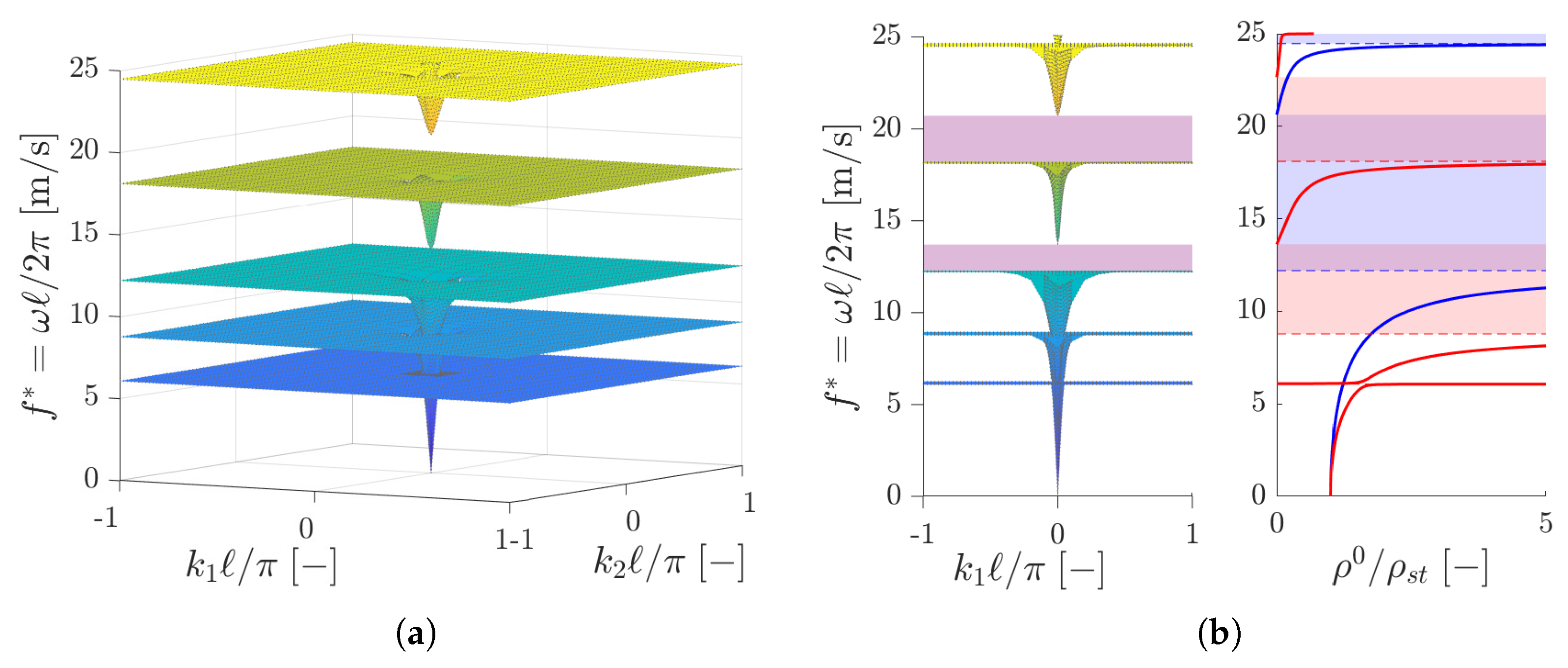
3.2. Dispersion Properties: Band Gaps and Polarization Bands

To obtain the dispersion relation of the homogenized media, we consider the propagation of the wave:
U 0 ( x ) = p e i k · x ,
where p is the polarization vector, k = k n is the wavevector, k is the wavenumber and n is the direction of propagation. Replacing (17) in the homogenized Helmholtz Equation (13), one obtains
Q 0 ( n ) c 2 ρ 0 ( ω ) · p = 0 ,
where c = ω / k is the phase velocity and Q 0 ( n ) is the effective acoustic tensor of the media defined as
Q 0 ( n ) = n · D 0 · n .
The latter is a second-order symmetric tensor due to the symmetries of D 0 , and it is also positive definite. In fact, due to the strong ellipticity condition (8), one has
v · Q 0 · v = n v : D 0 : n v α v 2 > 0 v 0 .
Equation (18) can be recognized as a generalized eigenvalue problem. Since Q 0 and ρ are real and symmetric, Equation (18) defines two real eigenvectors p α and p β associated with the real eigenvalues c α 2 and c β 2 , which solve the dispersion relation:
det [ Q 0 ( n ) c 2 ρ 0 ( ω ) ] = 0 .
The eigenvectors p α and p β , which in general do not coincide with e I and e II , satisfy the orthogonality conditions:
p α · Q 0 · p β = p α · ρ 0 · p β = 0 ,
while the eigenvalues c α 2 and c β 2 can be expressed through the Rayleigh quotients:
c α 2 = p α · Q 0 · p α p α · ρ 0 · p α and c β 2 = p β · Q 0 · p β p β · ρ 0 · p β .
Since Q 0 is positive definite, the numerators of Equation (23) are always positive, which means that the sign of c α 2 and c β 2 is determined by the spectral properties of the effective mass tensor. In our two-dimensional problem, three different cases can be distinguished, which are indicated in Figure 2b with circled numbers.
Case ➀:  ρ 0 is positive definite (i.e., ρ I 0 and ρ II 0 are positive).
In this case, one has p · ρ 0 · p > 0 for every p 0 , which means, from (23), that both c α 2 and c β 2 are positive. In the frequency ranges where the effective mass is positive definite, called pass bands, Equation (21) admits two positive real wave velocities c α and c β , i.e., elastic waves can propagate within the metamaterial with polarization vectors p α and p β .
Case ➁:  ρ 0 is negative definite (i.e., ρ I 0 and ρ II 0 are negative).
Unlike the previous case, now p · ρ 0 · p < 0 for every p 0 . Therefore, from Equation (23) one has that c α 2 and c β 2 are both negative, i.e., Equation (21) has no real solution. In frequency intervals where the effective mass is negative definite, called band gaps, elastic waves cannot propagate without being attenuated.
The purple-shaded regions of Figure 2b, i.e., the superposition of the blue and red ones, correspond to the band gaps of the locally resonant metamaterial. To validate this result, we performed a Bloch–Floquet numerical analysis on the same metamaterial considered in Figure 2. The resulting dispersion surfaces are shown in Figure 4b on the whole First Brillouin Zone of the lattice, which in this case is a square of side 2 π / .
Figure 4b shows, on the left, a side view of the dispersion surfaces of Figure 4a. In purple, the band gaps obtained through Bloch-Floquet -analysis are shaded: they are in good agreement with those predicted by the proposed homogenization approach as the interval of negative definition of the effective mass tensor (Figure 4b, on the right).
Case ➂:  ρ 0 is indefinite (i.e., ρ I 0 and ρ II 0 have opposite signs).
In this situation, the sign of p · ρ 0 · p cannot be established a priori. Introducing the tensor
P = p α e I + p β e II ,
and making use of the orthogonality conditions (22), it is possible to show that
P · ρ 0 · P = ( p α · ρ 0 · p α ) e I e I + ( p β · ρ 0 · p β ) e II e II .
Since ρ 0 and P · ρ 0 · P are congruent tensors, due to Sylvester’s law of inertia, they share the same signature. Thus, p α · ρ 0 · p α and p β · ρ 0 · p β (which are the eigenvalues of P · ρ 0 · P ) have opposite sign as the eigenvalues ρ I 0 and ρ II 0 of the effective mass tensor. From (23), one can deduce that also c α 2 and c β 2 have different signs and, therefore, Equation (21) admits only one real solution. Elastic waves hence propagate with a unique phase velocity (i.e., the positive eigenvalue) and a unique polarization vector (i.e., the associated eigenvector), and the corresponding frequency intervals are called polarization bands.
Without loss of generality, let us suppose that ρ I 0 > 0 , ρ II 0 < 0 and let c α 2 be the positive eigenvalue. This implies, from (23), that
p α · ρ 0 · p α > 0 .
Making use of (16) and expressing the polarization vector as p α = cos φ e I + sin φ e II , being that φ is the angle that p α forms with e I , the previous inequality can be rewritten as
ρ I 0 cos 2 φ + ρ II 0 sin 2 φ > 0 ,
which implies:
tan 2 φ < ρ I 0 | ρ II 0 | .
Equation (28) provides an upper bound estimation of φ , i.e., of the angle between the polarization vector p α and the direction of positive effective mass e I . In particular, when ρ I 0 / ρ II 0 0 , one has φ 0 and, hence, p α e I . This means that, when the ratio between the positive and negative principal masses is sufficiently small, the polarization vector becomes aligned with the principal direction of the positive effective mass. These frequency intervals can be therefore exploited to damp out elastic waves which are not polarized as the direction of positive principal effective mass, thus obtaining a mode conversion mechanism.

3.3. Phase Velocity Diagrams

Let us consider the same metamaterial of Figure 2b with horizontally eccentric fibers ( ϑ = 0 ). For small values of the frequency, the principal values of the effective mass are positive (pass band) and quite similar, i.e., the mass tensor is almost isotropic. However, due to the anisotropy of the acoustic tensor, the wave phase velocities c α and c β depend on the direction n of propagation. This can be visualized through the polar diagram of Figure 5a, in which the two-wave phase velocities are shown in black as a function of n , for f * = 2 m/s. In the same figure, green lines represent the direction of propagation of the elastic waves, which are given by the corresponding polarization vectors p α and p β . One can recognize a behavior similar to that of isotropic materials with longitudinal and shear waves.
If we select a higher frequency f * = 8 m/s, always belonging to a pass band, the anisotropy of the mass tensor increases, and the wave phase velocities are modified; see Figure 5b.
When considering a frequency belonging to a red polarization band where ρ II 0 < 0 , e.g., f * = 8.8 m/s, only one real phase velocity exists. In this case, the ratio ρ I 0 / | ρ II 0 | = 0.025 is quite small and, hence, the polarization directions of the propagating elastic waves, as shown in Figure 5c, are aligned with the direction of positive mass.
For a higher frequency within the same polarization band, e.g., f * = 11.6 m/s, see Figure 5d, the ratio ρ I 0 / | ρ II 0 | = 1.12 increases, and the polarization directions are no longer horizontal.

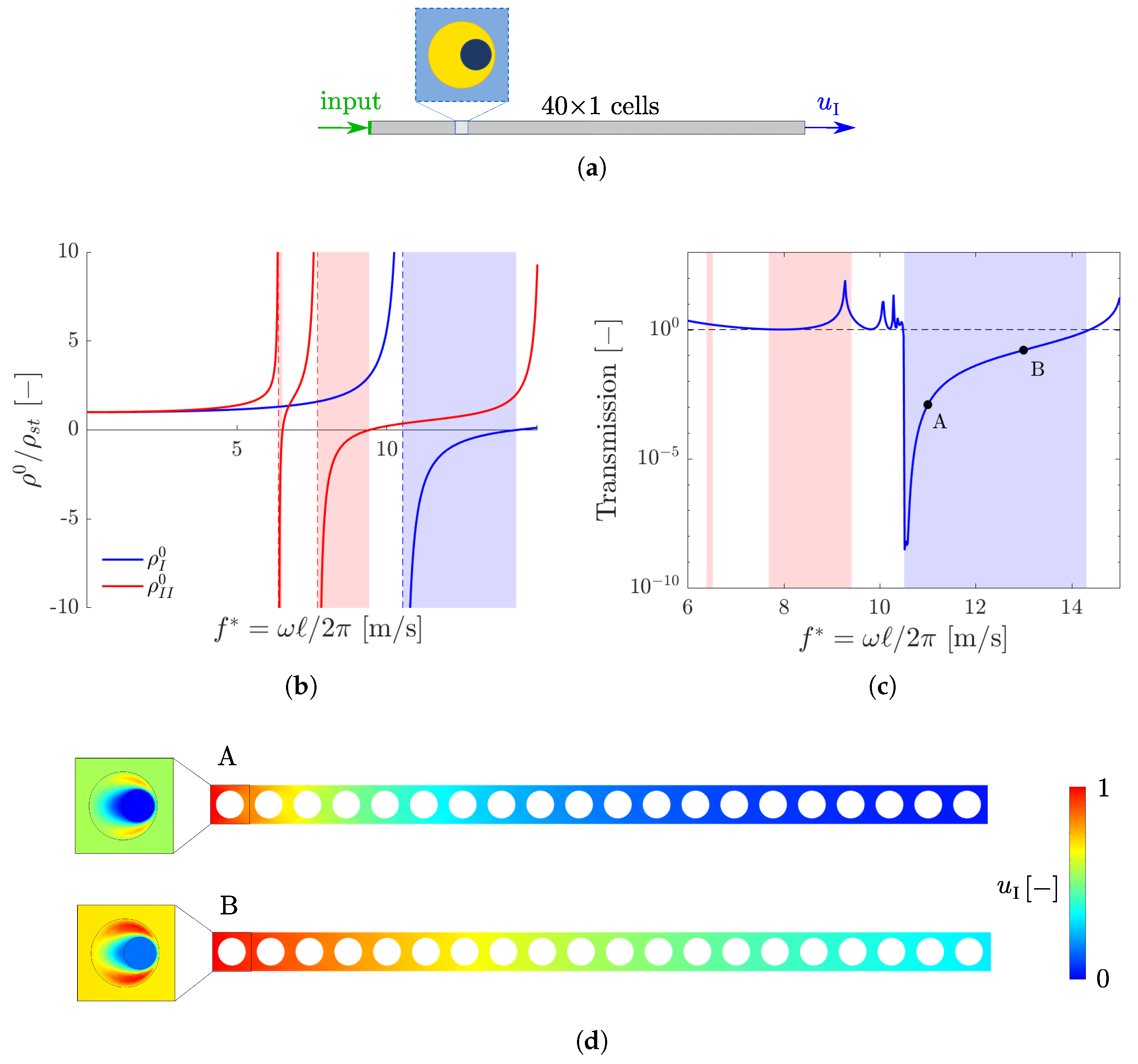
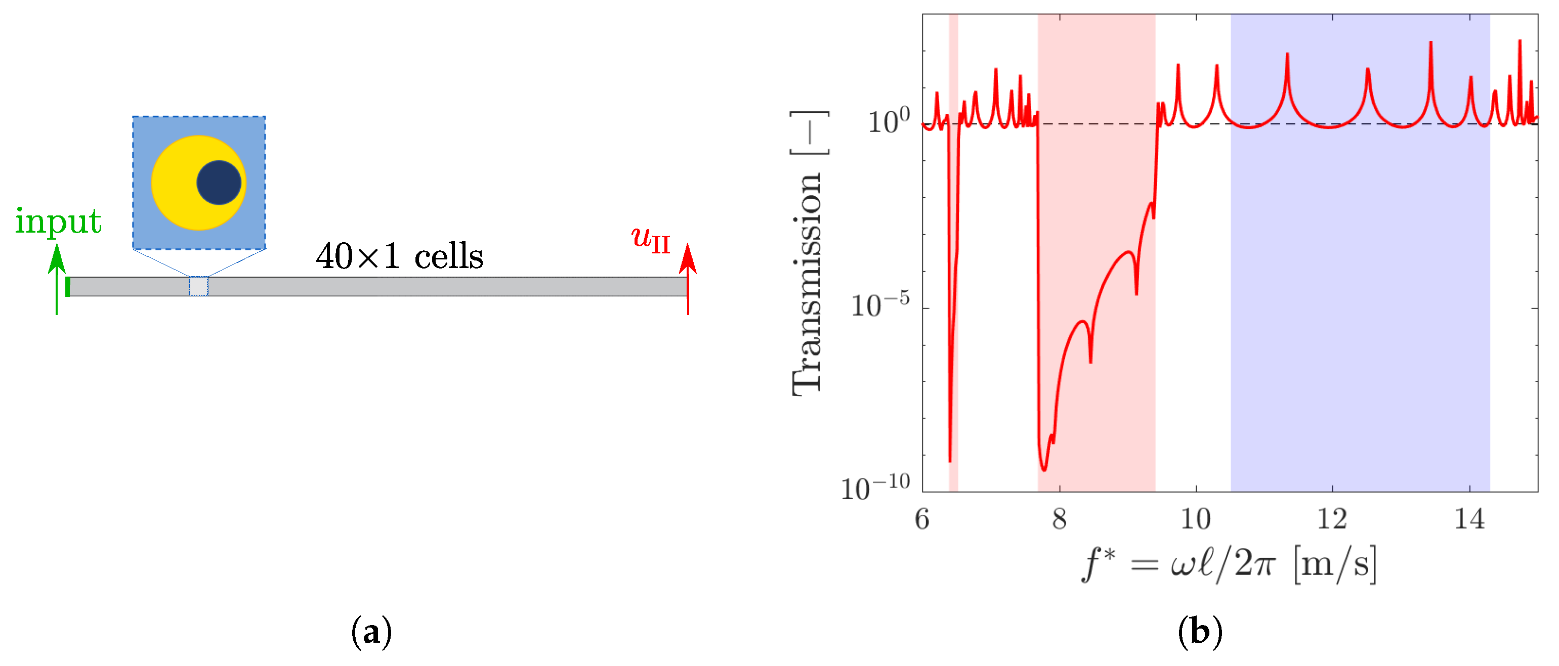
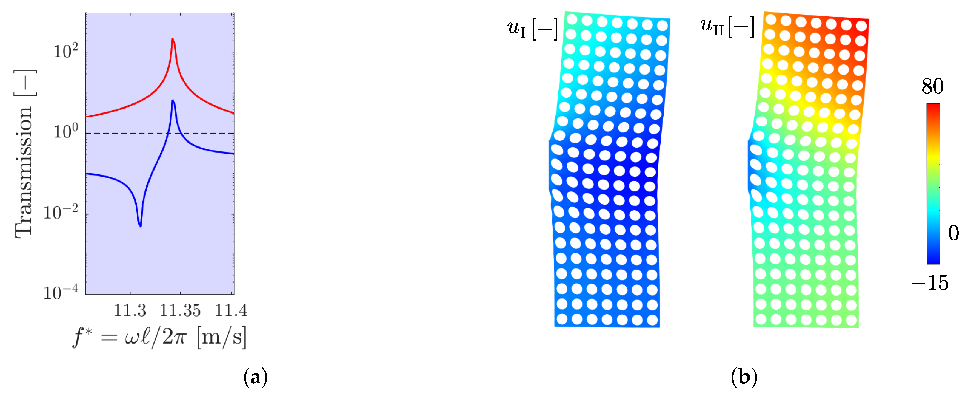
4. Transmission Analyses

To validate the polarization band properties investigated through asymptotic homogenization, we perform several numerical transmission analyses employing the real geometry of the locally resonant metamaterial. For this purpose, we consider two different geometries of the unit cell, characterized by the same geometrical dimensions ( R c / = 0.36 , R f / = 0.17 and e / = 0.15 ) but with two different angles of eccentricity of the fibres: ϑ = 0 and ϑ = π / 4 .
The adopted geometric dimensions of the metamaterial cell allow to completely separate the intervals in which the principal values of ρ 0 ( ω ) are negative as shown in Figure 6b such that no complete band gaps are present.

4.1. Eccentricity with ϑ = 0

As a first example, we consider an array of 40 cells with horizontally eccentric fibers ( ϑ = 0 ), as shown in Figure 6a. The medium is excited by a unit displacement applied on the left end in the e 1 direction, which coincides with the principal mass direction e I of the metamaterial. Figure 6c shows the response of the system, in terms of the displacement u I evaluated on the right end of the cell array, as a function of the reduced frequency f * . As it is possible to observe, elastic waves, which are polarized in the e I direction, are damped only in the blue shaded interval, i.e., where ρ I 0 < 0 .
The absorption is higher at the opening of the polarization band, i.e., where the negative mass ρ I 0 , and becomes smaller as the frequency increases. This is also visualized through the contours of the displacement u I of the matrix, shown in Figure 6d for f * = 11 m/s (point A of Figure 6c) and f * = 13 m/s (point B of Figure 6c), for the first twenty cells of the metamaterials. For the lowest frequency (A), fifteen cells are enough to completely damp out the propagating wave, whilst for the highest one (B), more than twenty cells are required.
In the same figure, on the left, the contour of the horizontal displacement on a whole unit cell is shown as well with a different color scale in order to appreciate the variation of the u I field inside the cell leading to a locally resonant mechanism.
We also consider the transmission, on the same system, of a unit displacement in the e 2 direction, as illustrated in Figure 7a. The response of the array is evaluated in terms of the displacement u II of the right edge of the array, and the transmission is plotted in Figure 7b. Since the propagating waves are polarized in the e II direction, the absorption is now present in the red polarization bands only, i.e., when ρ II is negative.

4.2. Eccentricity with ϑ = π / 4

We now consider a two-dimensional transmission problem on a domain, shown in Figure 8a, composed of 7 × 21 cells having eccentricity inclined at ϑ = π / 4 . We impose a unit displacement in the e I direction only on the central portion of the left edge. The response is evaluated in points P 1 and P 2 , on the right edge of the body, in terms of the displacement components in the principal direction of effective mass.
Figure 8b (resp. Figure 8c) shows the transmitted displacement u I (resp. u II ) versus frequency, evaluated in P 1 (continuous lines) and P 2 (dashed lines). Absorption of the elastic waves propagating in the media can be observed in the blue polarization band for u I (Figure 8b) and in the red ones for u II (Figure 8c). Nevertheless, the presence of a few peaks which are not completely damped out can be observed. These peaks, occurring in correspondence of eigenfrequencies of the holed matrix, arise due to the finite size of the domain under analysis and are dependent on the prescribed boundary conditions.
For example, Figure 9a shows a detail of the peak occurring at f * = 11.34 m/s in the transmission curves of u I and u II in P 1 . It can be noticed that, even if the displacement u I is not completely damped out in the blue polarization band, its magnitude is far lower than the one of u II . This fact can also be qualitatively observed if one looks at the contours of u I and u II for f * = 11.34 m/s shown in Figure 9b.

5. Conclusions

In this work, we studied the in-plane propagation of elastic waves in a ternary locally resonant metamaterial made of a connected stiff matrix and periodic cylindrical inclusions consisting of heavy fibers eccentrically coated by a soft material.
Two-scale asymptotic homogenization was employed to study the effective dynamic properties of the periodic media. The method provides a frequency-dependent mass density tensor that, in general, is anisotropic. We established that the signature of the effective mass tensor plays a crucial role in the dynamic properties of the media.
The propagation of elastic waves without attenuation is allowed when the effective mass tensor is positive definite (pass bands) and is forbidden when is negative definite (band gaps). In all the other cases, i.e., when the homogenized mass is indefinite (polarization bands), elastic waves can propagate with a unique polarization vector, whose direction tends to that of the principal positive effective mass as the ratio between the positive and negative effective mass tends to zero.
Finally, the results obtained through asymptotic homogenization were validated by comparing the predicted polarization bands with several numerical transmission analyses carried out on the real geometry of the metamaterial.
The results of the present work could help to predict polarization bands for the design and optimization of locally resonant metamaterials that manipulate elastic wave polarization and allow for mode-converting mechanisms. The outcome of this paper could also be generalized to three-dimensional locally resonant metamaterials and metaplates.

Author Contributions

Conceptualization, D.F. and C.C.; methodology, D.F., A.V. and C.C.; software, D.F. and F.M.; validation, F.M.; writing—original draft preparation, D.F.; writing—review and editing, all authors; supervision, A.V. and C.C. All authors have read and agreed to the published version of the manuscript.

Funding

This research received no external funding.

Data Availability Statement

The data presented in this study are available on request from the corresponding author.

Conflicts of Interest

The authors declare no conflict of interest.

References

  1. Liu, Z.; Liu, Z.; Zhang, X.; Mao, Y.; Zhu, Y.Y. Locally Resonant Sonic Materials. Science 2000, 289, 1734–1736. [Google Scholar] [CrossRef] [PubMed]
  2. Comi, C.; Moscatelli, M.; Marigo, J.J. Two scale homogenization in ternary locally resonant metamaterials. Mater. Phys. Mech. 2020, 44, 8–18. [Google Scholar]
  3. Tan, K.T.; Huang, H.H.; Sun, C.T. Blast-wave impact mitigation using negative effective mass density concept of elastic metamaterials. Int. J. Impact Eng. 2014, 64, 20–29. [Google Scholar] [CrossRef]
  4. D’Alessandro, L.; Ardito, R.; Braghin, F.; Corigliano, A. Low frequency 3D ultra-wide vibration attenuation via elastic metamaterial. Sci. Rep. 2019, 9, 3–10. [Google Scholar] [CrossRef] [PubMed]
  5. Sugino, C.; Ruzzene, M.; Erturk, A. Merging mechanical and electromechanical bandgaps in locally resonant metamaterials and metastructures. J. Mech. Phys. Solids 2018, 116, 323–333. [Google Scholar] [CrossRef]
  6. Comi, C.; Driemeier, L. Wave propagation in cellular locally resonant metamaterials. Lat. Am. J. Solids Struct. 2018, 15, 1–15. [Google Scholar] [CrossRef]
  7. Park, J.; Lee, D.; Rho, J. Recent advances in non-traditional elastic wave manipulation by macroscopic artificial structures. Appl. Sci. 2020, 10, 547. [Google Scholar] [CrossRef]
  8. Huang, Y.; Wu, J.H.; Lei, Y.; Niu, J. Impact protection enhancement by negative mass meta-honeycombs with local resonance plates. Compos. Struct. 2023, 321, 117330. [Google Scholar] [CrossRef]
  9. Calius, E.P.; Bremaud, X.; Smith, B.; Hall, A. Negative mass sound shielding structures: Early results. Phys. Status Solids B 2009, 246, 2089–2097. [Google Scholar] [CrossRef]
  10. Lee, S.H.; Wright, O.B. Origin of negative density and modulus in acoustic metamaterials. Phys. Rev. B 2016, 93, 024302. [Google Scholar] [CrossRef]
  11. Bensoussan, A.; Lions, J.L.; Papanicolaou, G. Asymptotic Analysis for Periodic Structures; North-Holland Publishing Company: Amsterdam, The Netherlands, 1978; p. 700. [Google Scholar]
  12. Auriault, J.L.; Bonnet, G. Dynamique des composites élastiques périodiques. Arch. Mech. 1985, 37, 269–284. [Google Scholar]
  13. Auriault, J.L. Acoustics of heterogeneous media: Macroscopic behavior by homogenization. Curr. Top. Acoust. Res. 1994, 1, 63–90. [Google Scholar]
  14. Craster, R.V.; Kaplunov, J.; Pichugin, A.V. High-frequency homogenization for periodic media. Proc. R. Soc. A Math. Phys. Eng. Sci. 2010, 466, 2341–2362. [Google Scholar] [CrossRef]
  15. Comi, C.; Marigo, J.J. Homogenization Approach and Bloch-Floquet Theory for Band-Gap Prediction in 2D Locally Resonant Metamaterials. J. Elast. 2020, 139, 61–90. [Google Scholar] [CrossRef]
  16. Faraci, D.; Comi, C.; Marigo, J.J. Band Gaps in Metamaterial Plates: Asymptotic Homogenization and Bloch-Floquet Approaches. J. Elast. 2022, 148, 55–79. [Google Scholar] [CrossRef]
  17. Bonnet, G.; Monchiet, V. Negative refraction of elastic waves on a metamaterial with anisotropic local resonance. J. Mech. Phys. Solids 2022, 169, 105060. [Google Scholar] [CrossRef]
  18. Yang, X.; Chai, Y.; Li, Y. Metamaterial with anisotropic mass density for full mode-converting transmission of elastic waves in the ultralow frequency range. AIP Adv. 2021, 11, 125205. [Google Scholar] [CrossRef]
  19. Ma, G.; Fu, C.; Wang, G.; Del Hougne, P.; Christensen, J.; Lai, Y.; Sheng, P. Polarization bandgaps and fluid-like elasticity in fully solid elastic metamaterials. Nat. Commun. 2016, 7, 13536. [Google Scholar] [CrossRef] [PubMed]
  20. De Ponti, J.M.; Iorio, L.; Riva, E.; Ardito, R.; Braghin, F.; Corigliano, A. Selective Mode Conversion and Rainbow Trapping via Graded Elastic Waveguides. Phys. Rev. Appl. 2021, 16, 034028. [Google Scholar] [CrossRef]
  21. Clement, G.T.; White, P.J.; Hynynen, K. Enhanced ultrasound transmission through the human skull using shear mode conversion. J. Acoust. Soc. Am. 2004, 115, 1356–1364. [Google Scholar] [CrossRef] [PubMed]
Figure 1. (a) Geometry of locally resonant metamaterial. (b) Unit cell with fiber and eccentric coating.
Applsci 13 10797 g001
Figure 2. (a) Geometry of the square unit cell with eccentric fiber; (b) principal values of the homogenized mass as a function of the reduced frequency for R f / = 0.24 , R c / = 0.36 and e / = 0.1 . Circled numbers represent the three cases discussed in Section 3.2.
Applsci 13 10797 g002
Figure 3. Contours of the first four eigenmodes of the inclusion fixed at its boundary for R f / = 0.24 , R c / = 0.36 , e / = 0.1 and ϑ = 0 . Top row: horizontal displacement; second row: vertical displacement. (a) f * = 6.08 m/s; (b) f * = 8.78 m/s; (c) f * = 12.22 m/s; (d) f * = 18.11 m/s.
Applsci 13 10797 g003
Figure 4. (a) Dispersion surfaces on the whole First Brillouin Zone; (b) comparison between the band gaps obtained through Bloch–Floquet analysis (left) with those predicted by homogenization (right).
Applsci 13 10797 g004
Figure 5. Polar diagrams of effective wave phase velocity (in black), expressed in m/s, as a function of the propagation direction for different values of frequency. Green segments give the polarization directions; (a) f * = 2 m/s; (b) f * = 8 m/s; (c) f * = 8.8 m/s; (d) f * = 11.6 m/s.
Applsci 13 10797 g005
Figure 6. Transmission analysis with ϑ = 0 : (a) model for the e 1 transmission; (b) principal values of the homogenized mass; (c) u I —transmission as a function of frequency; (d) contour of u I in the first twenty cells for: (A) f * = 11 m/s and (B) f * = 13 m/s.
Applsci 13 10797 g006
Figure 7. (a) Model for the e 2 —transmission analysis with ϑ = 0 ; (b) u II —transmission as a function of frequency.
Applsci 13 10797 g007
Figure 8. (a) Model for the transmission analysis with ϑ = π / 4 ; (b) transmission of u I at point P 1 (continuous line) and P 2 (dashed line); (c) transmission of u II at point P 1 (continuous line) and P 2 (dashed line).
Applsci 13 10797 g008
Figure 9. (a) Detail of the transmission curve of u I (blue) and u II (red) in P 1 around f * = 11.34 m/s. (b) Contours of u I and u II on the matrix only for f * = 11.34 m/s.
Applsci 13 10797 g009
Disclaimer/Publisher’s Note: The statements, opinions and data contained in all publications are solely those of the individual author(s) and contributor(s) and not of MDPI and/or the editor(s). MDPI and/or the editor(s) disclaim responsibility for any injury to people or property resulting from any ideas, methods, instructions or products referred to in the content.

