Article

Development of a Conveyor Cart with Magnetic Levitation Mechanism Based on Multi Control Strategies

1
Division of Electronics and Informatics, Gunma University, 1-5-1 Tenjin-cho, Kiryu 376-8515, Gunma, Japan
2
Yangzhou Polytechnic Institute, No. 188 Huayangxilu, Yangzhou 225127, China
3
Sanki Engineering Co., Ltd., 7-10-1 Chuorinkan, Yamato 242-0007, Kanagawa, Japan
*
Author to whom correspondence should be addressed.
Appl. Sci. 2023, 13(19), 10846; https://doi.org/10.3390/app131910846
Submission received: 10 July 2023 / Revised: 27 September 2023 / Accepted: 27 September 2023 / Published: 29 September 2023
(This article belongs to the Special Issue Electric Power Applications II)

Abstract

:
This paper presents the experimental magnetic levitation control development of Sanki Engineering airport luggage conveyor carts which have four magnetic levitation units working synchronously. With the PID controller, the state feedback controller and the zero-power controller refined by PID controller were implemented in the one magnetic levitation unit system and four-unit magnetic levitation system, and the displacement and the current were verified in a real-time system. The magnetic levitation unit had a fast response, and the control algorithms were easily implemented. The change of current and displacement were compared. In the one-unit system, the PID and state feedback controller react to the disturbance at the same speed and have similar power consumptions. For a disturbance on the zero-power controller, the system generates a transient current to deal with the load disturbance and finally settles to 0 A. The PID control for four magnetic levitation units of the conveyor cart has a better stable performance during synchronous operation. Under the control of state feedback controller, they can keep the cart statically stable with some oscillation. These characteristics are experimentally confirmed.

1. Introduction

Magnetic levitation technology can transport objects without contacting the ground whereby the system generates high-speed motion and eliminates vibrations. This innovative technology is widely used in various applications such as magnetic levitation trains, magnetic levitation bearings, and high-speed elevators [1,2]. In many airports, magnetic levitation conveyor cart technology has been widely applied worldwide. The magnetic levitation transport conveyor carts have the advantages of high speed, high efficiency, low noise, and low energy consumption, which can greatly improve the efficiency of baggage transportation [3,4,5].
This paper explores the design of a control system for a magnetic levitation conveyor that utilizes four magnetic levitation units for support. Unlike the conventional magnetic levitation transport systems that typically employ a single magnetic unit, the magnetic levitation conveyor described in this paper features a rectangular transport platform upheld by four magnetic float units. This platform is specifically designed for the transportation of baggage. The entire magnetic levitation conveyor system is suspended from a rail by means of the four magnetic levitation units. These four magnetic float units operate in tandem, marking a distinctive and innovative departure from the conventional magnetic levitation transport systems. The primary objective is to implement the magnetic levitation mechanism into the conveyor system and assess its performance alongside several existing control ideas.
In this paper, levitation control is performed by several typical feedback control methods used in magnetic levitation control. The different control strategies of the magnetic levitation unit constitute the core part in this paper. For the traditional magnetic levitation system, which is the second order nonlinear system, the original system cannot keep the cart stable. A PD or PID controller must be applied for the system to achieve stability [6]. There are three control strategies which are applied in the magnetic levitation units of the conveyor cart. The three controllers are the basic PID controller, the state feedback controller, and the zero-power controller. A single controller applied in a magnetic unit is common, but the four controllers that work in sync are main target of research in this experiment [7]. The four-unit design enables the magnetic levitation conveyor cart to carry a heavier mass.
This paper focuses on the mechanical structures and primary components of the magnetic levitation conveyor cart in Section 2. In Section 3, an analysis of the magnetic levitation force process is provided. Section 4 delves into the analysis of the mathematical model of the magnetic levitation unit, along with the design of the PID controller, state feedback controller, and zero-power controller. The experimental results for all controllers, both for single-unit and four-unit configurations, are presented. The concluding Section 5 provides a summary of the findings and outlines future recommendations.

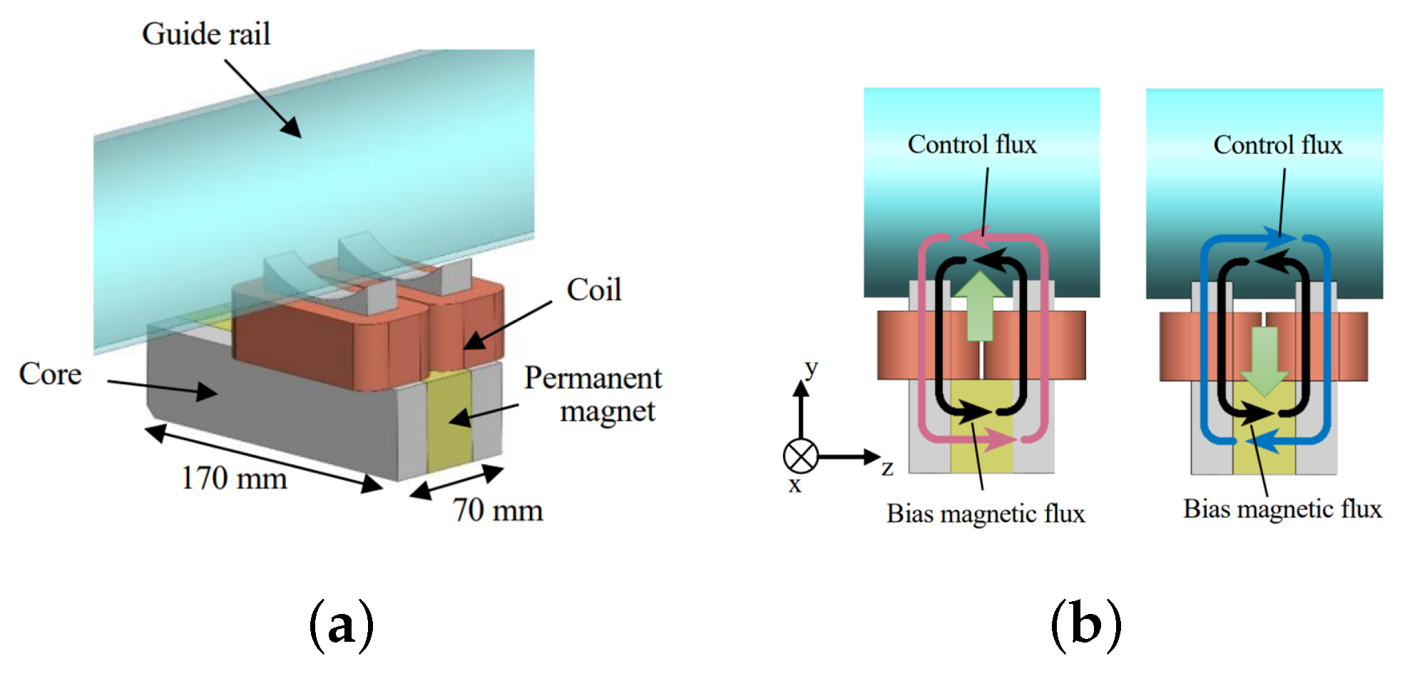
2. Mechanical Structure of Magnetic Levitation Conveyor

Figure 1 illustrates the mechanical structure of the Maglev unit, while Figure 1a provides a schematic representation of the core unit responsible for generating the magnetic levitation force. The core unit was designed with a configuration where a permanent magnet was positioned between the two cores (manufactured by SUY1), with a coil wound around the core’s protrusion. Each coil consisted of 670 turns, and two coils were connected in series. Figure 1b elucidates the operational principle of the core unit. Due to the permanent magnet’s magnetization along the z axis, it established a bias magnetic flux path, as indicated by the black arrow within it. The bias magnetic flux traveled from the permanent magnet to the right core, passed through the air gap, and entered the guide rail. Subsequently, the magnetic flux that entered the left core through the air gap returned to the permanent magnet. This magnetic path created an attractive force between the core and the rail, thereby providing support for the transport device. By applying a control current to the electromagnet, the strength of the bias flux could be adjusted. When a forward control current was applied, it generated a control magnetic flux in the same direction as the bias magnetic flux, consequently increasing the magnetic flux density in the air gap between the core and the rail, thereby boosting the levitation force. Conversely, when a reverse control current was applied, a control magnetic flux opposing the bias magnetic flux was generated, leading to a reduction in the magnetic flux density in the air gap and subsequently decreasing the levitation force. The core unit’s support force was fine-tuned according to this principle.
As depicted in Figure 2, we conducted a magnetic field analysis to elucidate the bearing capacity characteristics of the core unit. For this purpose, we employed the finite element method magnetic field analysis software JMAG-Designer ver.20.0 (provided by Japan JSOL corporation Tokyo head office). Magnetic levitation force simulations were carried out using JMAG-Designer Ver.21.0.01zs prior to the physical measurements. JMAG is a specialized simulation software widely used for the development and design of electrical devices. It was originally released in 1983 as a tool to support the design of various devices, including motors, actuators, circuit components, and antennas [8]. Figure 2a illustrates the model used for the magnetic field analysis, and Table 1 presents the analysis conditions. In this analysis, we displaced the core unit by ±2.0 mm in the y direction, with the center point corresponding to a 4 mm air gap between the guide rail and the core. The control current was set to three different levels: 3 A, 0 A, and 3 A. Figure 2b presents the results of the analysis. When the control current was set to 0 A, utilizing only the bias levitation force generated by the permanent magnet, the levitation force per magnetic levitation unit ranged from 633 N to 952 N as the air gap varied from 2.0 mm to 6.0 mm. Furthermore, it is observed that, by adjusting the control current from 3 A to −3 A, a levitation force ranging from 476 N to 1054 N could be achieved. Figure 2b clearly demonstrates the core unit’s capability to generate variable levitation forces based on changes in both the air gap and control current.
An experimental apparatus was fabricated based on the results of the magnetic field analysis to realize magnetic levitation. Figure 3a presented a photograph of the manufactured magnetic levitation unit. The magnetic levitation unit consisted of a core unit, an eddy current displacement sensor, a touchdown wheel, and a side wheel, all attached to the bracket. Three touchdown wheels were utilized to limit the vertical range of motion for the transport device, while the horizontal displacement was constrained by the side wheels. The design specification for the vertical movable range was ±1.0 mm, with the reference point being an air gap of 4.0 mm. The fabricated magnetic levitation unit was then mounted on the carrier. Figure 3b showed an overall photograph of the transfer device. Four magnetic levitation units were employed to support the cart and conveyor section of the transfer system. The guide rail, cart, and conveyor depicted in Figure 3c were part of the existing transport equipment, and the implementation of the magnetic levitation unit required minimal modifications to the structure. The total weight of the carrier was 130 kg. Under the condition of an air gap of 4.0 mm and a control current of 0 A, the combined supporting force of the four magnetic levitation units, solely from the permanent magnets, amounted to approximately 3000 N (equivalent to about 300 kg). Thus, it was anticipated that the supporting force provided by the permanent magnets would exceed the weight of the carrier. During the levitation experiment, weights were added to the conveyor to counterbalance the supporting force of the permanent magnets. These modifications and the introduction of the experimental apparatus allowed for the implementation of magnetic levitation, enabling further investigations and evaluations.

3. Magnetic Levitation Unit Support Force Analysis

Magnetic Levitation Transfer Equipment Position Measurement Circuit

The magnet levitation support force measurement is the basic condition to analyze the magnetic levitation conveyor cart system. Figure 4 shows the structure of the designed suspension force measurement device.
The magnetic force measurement apparatus consists of a core unit, a plate spring to which a strain gauge is attached, a side panel, an eddy-current displacement sensor, and a laser displacement transducer. The side panel is fixed to the plate spring. When a rail is placed on the side panel, a suspension force is generated between the rail and the core. Since the rail is supported by the side panel, the core unit is pulled toward the rail which generates displacement and strain on the plate spring. This strain is detected by strain gauges attached to the bottom of the plate spring to determine the support force. The position of the rails can be adjusted by inserting spacers between the side panels and the rails. Thus, this allows the gap dependence of the support force by the core unit to be measured. The detailed position of the rail was measured by an eddy-current displacement sensor which is attached to the side panel. The displacement of the core unit during suction was measured with a laser displacement meter attached separately.
The magnetic force is determined by analyzing the output of strain gauges when the rail is placed on the attachment force measuring device. For data acquisition and processing, we utilized the dSPACE DS1104 Digital Signal Processor in this experiment. Additionally, to measure the displacement of the core unit during suction, a laser displacement meter was employed. During the measurement process, we inserted spacers between the rail and the side panel, as illustrated in Figure 4, to deliberately adjust the gap between the core and the rail. This adjustment allowed us to precisely measure the suction force. The exact position of the rail was confirmed using eddy current displacement sensors that were securely attached to the side panels. In our assessment of adsorption force, we also recorded variations in the adsorption force resulting from the application of control current to the coil.
In the suspension force measurement experiment, we systematically varied the gap between the rail and the magnetic levitation unit to the following values: 0.7 mm, 2.4 mm, 3.9 mm, 5.2 mm, and 6.8 mm. Concurrently, we applied a range of input currents, including −3 A, −2 A, −1 A, 0 A, 1 A, 2 A, and 3 A. This enabled us to investigate the influence of both current and air gap on the magnetic force. Of particular interest is the scenario when the current is set to 0 A. In this condition, the magnetic levitation force is primarily generated by the permanent magnet (PM).
Figure 5 displayed the results of attaching the core unit to the rail and measuring the bearing force. When comparing these measurement results with the magnetic field analysis results shown in Figure 2b, it was observed that the measured values were approximately 30% lower than the analytical values. The supporting force provided by the permanent magnets alone per unit, at an air gap of 4.0 mm, amounted to 560 N. By combining the forces generated by all four magnetic levitation units, we were able to achieve a total levitation force of approximately 2240 N. Moreover, the levitation force has a movable range ranged from 1520 N to 2800 N in the air gap and control current adjustable range. Although the sum magnetic force of four units was lower than the result of the magnetic field analysis, it still could levitate the weight of the carrier cart and baggage.
The initial design specifications for each magnetic levitation unit called for a support force of 750 N when no current input (0 A) was applied. However, the actual measured force obtained from our experimental results was found to be less than what had been predicted by the JAMG magnetic field analysis. Several factors contributed to this discrepancy. Firstly, the accuracy of the gap between the rail and the core unit was not consistent with the design specifications. This variation in the gap size had a direct impact on the resulting force measurements. Secondly, as part of the measurement setup, spacers were indeed inserted between the side panel and the rail. These spacers were used to adjust the gap between the core and the rail, as mentioned earlier. This introduced an additional variable that affected the measured forces. Lastly, it is worth noting that, after multiple uses of the measuring device, there was a possibility that the paint on the rails gradually peeled off. This could also have contributed to variations in the measured forces over time. These findings demonstrated the effectiveness of the magnetic levitation unit in achieving the desired levitation force, providing valuable insights for further development and application.

4. Magnetic Levitation Unit Controller Strategies

4.1. Electrical Circuit of Four Magnetic Levitation Unit

In the experimental magnetic levitation unit system, the electrical processing circuit with the controller is designed to keep the system stable. The electrical processing circuit consists of the DSP, current amplifier, sensor measurement circuit and coil. The DSP used in this experiment is dSPACE DS1104. The dSPACE real-time simulation system is a MATLAB/Simulink-based control system development and testing work platform developed by dSPACE, which realizes a completely seamless connection with MATLAB/Simulink. The dSPACE real-time system has a hardware system with high-speed computing capabilities, including processors, I/O, etc. And, it has a convenient and easy-to-use software environment for code generation/download and testing/debugging [9]. The eddy-current displacement sensor attached to the magnetic levitation unit detects the vertical displacement and inputs the displacement signal to the dSPACE. The dSPACE deals with the input sensor signal, then generates the command value for the control current which is output to the coil amplifier. The current amplifier will change the modified voltage signal to a current signal to input in the coil. The coil will generate enough levitation force to support the magnetic levitation unit float. The vertical position of the units is continuously detected by the eddy current sensor. Figure 6 shows the structure of the electrical logic circuit.

4.2. Magnetic Levitation Math Model Analysis

To build the mathematical model of the magnetic levitation car system, there are some assumptions to be set:
  • Magnetic flux leakage, edge effect and the reluctance between the rail and the electromagnet are ignored [10]
  • The electromagnet unit is a homogeneous sphere, the magnetic force is concentrated on the center of it [10]
  • There is a linear relationship between the output current and input voltage of the power amplifier, and there is no delay [10]
Constructing a model for the control of a four-unit cart is important. However, when it comes to controlling the four-unit model, factors such as interference and slight deformations make precise control extremely challenging. Consequently, in this paper, for the simplicity of the control system design, we do not consider the four-unit model for control; instead, our focus is on controlling each individual unit.
To have a good-understanding of the mathematical relationship of the magnetic levitation system, Table 2 shows the parameters named in the nomenclature.
With the assumptions, the mathematical relationship of the magnetic levitation system can be established through the theoretical derivation. From Newton’s second law:
m d 2 x ( t ) d t 2 = F ( i , x ) + m g
where m is the mass of the float unit, g is the gravity acceleration, and x is the air gap of bracket coil and guide rail. F ( i , x ) is the electromagnetic force on the magnetic unit, and i is the instantaneous current of the electromagnet winding. Based on the Kirchhoff laws and Biot–Savart law of the magnetic circuit, the electromagnetic force on the float unit can be deduced as follows [11]:
F ( i , x ) = μ A N 2 4 ( i x ) 2
where K c is defined the K c = μ A N 2 / 4 , which is the constant coefficient related to the magnetic flux of the electromagnetic winding. When the bracket is in equilibrium position, the formula is obtained according to the mechanical balance principle as:
m g + F ( i 0 , x 0 ) = 0
which i 0 , x 0 are the air gap and the current in the coil when the magnetic levitation ball is in balance. Combing Equations (1)–(3) and taking their Laplace transform, the relationship shows Equation (4)
x ( s ) = k i m s 2 k s i ( s )
where k i = K c i 0 2 / 2 x 0 2 and k s = K c i 0 2 / 2 x 0 3 . In this research, we measure x 0 and i 0 at the selected equilibrium point, and thus, the k i and k s can also be obtained. The specific values are shown in Table 2.

4.3. Experimental Test of Magnetic Levitation Unit with PID Controller

4.3.1. The Basic Principle of PID Controller

The PID controller is a kind of feedback controller system which has been widely applied in industrial application [12]. The transfer function of the PID controller is given by [13]
G ( s ) = ( K p + K i 1 s + K d s ) e ( s )
where K p is the proportional gain, K i is the integral gain, K d is the derivative gain, e ( s ) is the error of the system, and G ( s ) is the controller output. Proportional gain is used to represent the control action equivalent to the error signal e ( s ) . The integral term provides the continuous integration of the error signal e ( s ) to minimize steady-state error, while the derivative term is used to improve the transient response. In the design, the PID controller design based on the displacement feedback is constantly compared with the input displacement. The PID controller parameters in the project were obtained from the experimental results, although the propulsion process is not present here. Figure 7 shows the flow chart of the PID controller applied in the plant.

4.3.2. Performance of Magnetic Levitation Unit with PID Controller

In order to measure the dynamic characteristics of the experimental device, one magnetic levitation unit experiment was conducted. One by one, the test shows the real dynamic characteristics of the actually fabricated experimental apparatus to obtain an accurate measurement and eliminate the influence from other disturbances. The chosen position is 4.0 mm, which is set as the reference point for the levitation balance position. It is the displacement of the air gap between the rail and the coil. The position of 4 mm represents the displacement 0 mm. Displacement change means that the magnetic levitation unit was displaced in the direction of the narrowing of the air gap. In the single magnetic levitation unit experiment, the other three units are fixed by inserting spacers which remain located in the displacement at 0 mm and without any current input. After the PID controller open, the displacement curve is near 0 mm and the current is on +0.1 A. Figure 8 shows the experimental results of one magnetic levitation unit.
The magnetic levitation unit was displaced by approximately 0.3 mm due to the load disturbance, and it returned to its original levitation position in approximately 1 s. The rise time was about 24 ms, the overshoot was about 40%, and the settling time was about 0.64 s. The quick response was fast enough for the application to a magnetic levitation conveyor cart. The displacement curve of the magnetic levitation unit has a consistent change in the target levitation position.
Then, we measured the response when a load was applied to the magnetic levitation unit. The levitation target value was fixed at 0 mm, a load of 8.0 kg was placed on the upper part of the bracket, and the displacement and control current were measured. The current axis in Figure 9 shows the disturbance load added on the magnetic levitation unit. The support force obtained from the magnetic levitation unit can support the load. The magnetic levitation generates a 0.3 mm displacement response to the disturbance, and it returned to the original levitation position in about 1 s. The control current increases from 0 A to 0.5 A. And, the movement of the displacement is very small. The device is supported by four magnetic levitation units which should support a load of 32 kg under the same conditions as in this experiment. Since the maximum weight of baggage that can be checked in at an airport is generally about 30 kg, this device is considered to have practical support force and dynamic characteristics.
Each magnetic levitation unit that works with the PID controller has to meet the design requirements and can keep the magnetic levitation unit stable after the disturbance is input. Because the magnetic levitation conveyor cart is a synchronous system comprising four magnetic levitation units, when the four magnetic levitation units turn on, the magnetic levitation units will influence each other. Figure 10 shows the displacement movement of each magnetic unit. In the system working with the same PID controllers, the four magnetic levitation units have a better collaborative performance. Although there are differences in the coils and the different working conditions, the PID controller has an excellently stable performance. The four magnetic levitation units’ output current has the same frequency with the displacement shows in Figure 10.

4.4. Experiment Test of Magnetic Levitation Unit with State Feedback Controller

4.4.1. The Basic Principle of the State Feedback Controller

In the former chapter, the PID controller which in the classical control theory is applied. Here, the feedback controller is applied to the plant [14]. The feedback control is designed to suppress initial disturbances. The normal feedback control is output feedback and state feedback. In our design, we choose the state feedback to control the plant which shows in Figure 11.
Feedback controllers feed every state parameter and multiply them with a corresponding coefficient to the system input. In the classical control theory, the poles will influence the system stability. To improve the response of the system and make the open-loop system stable, the poles should be freely determined. The performance of a control system largely depends on the distribution of the system poles in the root plane. Given a set of desired pole, we obtain the desired dynamic performance by selecting a feedback gain matrix [15].
To keep the displacement balance point at the zero point, a position servo integrator is placed before the feedback controller point [16]. The transfer function of the system is changed from second orders to third orders. Hence, three order poles which are based on the pole placement theory are placed in the left plate of the axis. Figure 12 shows that there are three feedback parameters, one which is the displacement of the system output, which is the f x ; and one is the velocity which is the f v . This uses an approximate derivative of the position to replace the speed of detection. The final one is the f s v . And, the amplifier k a m p is also considered in the system here.
First, represent the state space equation of the closed-loop dynamics:
x ˙ = A x + B υ y = C x + D u
and the output equation D = 0 .
In the classical controller theory, the poles were located in the left platform of the axis, the system can be stable. In the design of the feedback control law, the method of placing the pole is called pole placement. In the design process, the outside input should not be considered. A full-static feedback controller design is shown in Equation (7):
u = K x
where the minus symbol is used to show the negative feedback, the parameters K = k 1 , k 2 , k n is a gain matrix, and x is a state quantity.
K = k 1 , k 2 , k n
The closed-loop state space equation with the state feedback controller shows:
x ˙ = ( A B K ) x y = C x
For the new system, the controller should be designed before anything else. The controllability of the system should be judged beforehand.
rank [ B , A B , A n 1 B ] = q
In the state feedback controller of the magnetic levitation unit system, the r a n k = 3 is the same as the length of the matrix ( A B K ) . Hence, the magnetic levitation unit state is controllable. In this system, the poles are set as 10 , 10.2 , 10.4 .
Hence, the closed-loop transfer function is changed to an autonomous system. The stability of the closed-loop system is based on the matrix ( A B K ) x eigenvalue. The real parts of the eigenvalues are all strictly negative whilst the system is stable. In the calculation of the controllers K, we obtain the characteristic equation:
det | s I ( A B K ) | = 0
The configured closed-loop system also has a s descending power arrangement characteristic equation, which we set as:
| s I ( A B K ) | = ( s s 1 ) ( s s 2 ) ( s s 3 ) ( s s n ) = 0
Equations (11) and (12) are the same formula. When all the poles are smaller than 0, then the matrix parameters K can be calculated. The process of the pole placement has been finished. In this project, all the calculations in MATLAB are finished. From MATLAB, the controller matrix is K = [ 1.7 0.02 1.4 ] . In this project, f x = 1.7 , f v = 0.02 , and F s v = 1.4 , as presented in Figure 12.

4.4.2. Performance of Magnetic Levitation Unit with State Feedback Controller

In the case of the state feedback controller, Figure 13 shows the experimental result of the magnetic levitation float unit. The starting position of the magnetic float unit is from about 0.8 mm, which is touching the upside. When the state feedback controller is on, the coil generated about −0.5 A current to push or pull the magnetic levitation float unit. After about 0.8 s seconds, the float unit reaches 0 mm. Because there is some noise in the sensors, the final position has little oscillation. To keep the magnetic levitation float unit stable, a continuous current is generated. The value is only about −0.01 A. In Figure 13, at the horizontal time axis near 8 s, a disturbance of about 8 kg is input to the magnetic levitation unit. The magnetic levitation has a 0.5 mm damping movement. After about 1 s, the magnetic levitation float unit can recover the balance status. However, the system will generate a 0.3 A current to make the magnetic levitation float unit balance again.
A single magnetic levitation unit has met the design requirement and can maintain the balance of the magnetic levitation unit after the disturbance is input. In the magnetic levitation conveyor cart, which is a synchronous system comprising four magnetic levitation units, when the four magnetic levitation units turn on with the state feedback controllers, the magnetic levitation units will influence each other. The little difference in the coils and the different working conditions have a negative influence on the system stability. Figure 14 shows the displacement movement of four magnetic units. After the system starts, there are three units with an oscillation of 0.1 mm with a displacement of 0 mm. During the displacement oscillation, a current −0.8 A generated at the same frequency is shown in Figure 14. When the disturbance is input at 9 s, the four units will generate a transient displacement of about 0.8 mm and a transient current of about 1.1 A will deal with the disturbance. And, the adjustment time for the four-unit system is about 2 s.
Additionally, this paper also employs a high-performance control strategy using position-servo state feedback control for the three-unit configuration due to its three-point support and practical considerations. For the remaining unit, we propose utilizing a PD control strategy having a narrow control bandwidth without the precise position servo functionality to minimize interference as much as possible. For the load, which is too heavy in each unit, the cart oscillation phenomenon is very serious. Therefore, the schematic and analysis result of this idea are not present in this paper.
The PID and SFB controllers applied to the magnetic levitation unit have a better stable performance. However, it will cost some energy to deal with the load change in the system. Since the magnetic levitation conveyor cart is a long-term operation instrument, saving energy is an important issue in this research. Hence, a zero-power controller evolved from a PID controller was designed. The response of a 1/1-size magnetic levitation transfer unit was measured when it was levitated at a fixed position by the PID controller and then switched to zero-power control. Figure 15 shows a block diagram of zero-power control incorporated into a conventional PID control system. The zero-power control is the feedback of a current integral value. The PID controller first is turned on to levitate the magnetic unit to the target position, and then switches on the zero-power controller. The balance position will change to use more PM magnetic force to levitate the objection. Hence, the zero-power controller is based on a refined PID controller.
The zero-power control is implemented using a PID controller, where f i / s serves as an integrator to eliminate static errors in response to step disturbance inputs. In this case, f i is an experimentally tuned parameter, which, in the zero-power control loop, has a fixed value of 1. The feedback current is measured based on the output current from the dSPACE system and is subsequently fed back into the system input.
Figure 16 shows the displacement and current of the magnetic levitation unit. At 0 s, the PID controller was applied and the magnetic levitation unit was located on the displacement of 0 mm with a control current of −0.2 A. When the zero-power control was switched on, the levitation unit changed its levitation position to the displacement of −0.5 mm and the control current converged to 0 A. Hence, it was confirmed that the zero-power controller can expand the gap between the core and the rail. The zero-power controller can displace the load to a position which only uses the support force of the permanent magnet alone. And, it can also reduce the steady-state control current to zero. But, the adjustment time is a little long. The system with 5% damping needs a settling time of 4 s.
In response to the disturbance load change during zero-power control, the steady-state displacement before the load was about −0.5 mm. After the load was added, the displacement moved vertically downward 0.4 mm, the control current was increased, and the unit was displaced vertically upward to a steady state position. The steady state displacement was at 0.5 mm, and the current of the magnetic levitation unit went to 0 A. This shows that a 8 kg increase in load is supported by narrowing the gap between the core and the rail. The system results in 5% damping, and the settling time needs about 4 s. For the zero-power controller, this was achieved with four simultaneous units. The oscillation of the system was too heavy. Here, we will not present the result ofthe experiment with four units controlled by the zero-power controller.
During the assessment of energy consumption, primarily attributed to the copper coils, we compute the integrality of the instantaneous thermal power with respect to time within a 1 s interval during the stable levitation state. Subsequently, we derive the total energy consumption of the Maglev system corresponding to the levitation duration T, as demonstrated in Equation (13).
Q c = 1 t T T + t i 2 R i ( t ) d ( t )
The energy consumption of the Maglev system with the PD controller and integrating zero-power controller is sufficiently lower than that of the system only controlled by the PD controller. Taking the load of 30 kg into account, the heating energy consumption of the Maglev system is approximately 0.96 w. In 10 min of operation, the heating energy consumption of the PD combined with the zero-controller Maglev system is about 576 J. Compared with the PID controller, there will be a saving in energy consumption of 75%. The energy consumption significantly decreases when working with the levitation mass.

5. Conclusions and Future Work

The structural design of a synchronous four-unit work magnetic levitation conveyor cart was completed and tested in the experiment. The new structural design of the conveyor cart proves the capacity, adaptability, and stability of the baggage conveyor.
The magnetic levitation unit’s electromagnetic characteristics were simulated in JMAG and tested in the experiment. The unit provided enough electromagnetic force to support the load. The PID controller, the state feedback controller, and the zero-power controller were designed to make the second-order nonlinear magnetic levitation system stable. An isolated magnetic unit has perfect balance characteristics under the controller of the PID. Under the disturbance load input, the PID controlled magnetic levitation unit had a fast reaction. The displacement recovery to 0 mm was fast and the support current generated maintains the position. Compared to the PID controller, the state feedback controller in the magnetic levitation unit also has excellent performance. After applying a disturbance load to the magnetic levitation unit, it also quickly recovered from the 0 mm displacement. The generated current to support the disturbance was less than the PID controller. When the disturbance load on the unit was applied long-term, a zero-power controller based on a PID controller was used to save energy. The zero-power controller can deal with the disturbance load only with the PM force in the air gap work range.The advantage of the PID and zero-power controller applied in the unit could cut down the system energy consumption. And, the disadvantage of a zero-power controller is the long adjustment time.
When the four magnetic levitation units work together, the synchronous PID controllers work smoothly. The influence of each unit on the others is little and the conveyor cart remains stable in a levitation state. The state feedback controller also has a good experimental result, but the simultaneous influence of each unit can be difficult to control. There exists a 0.1 mm oscillation in each unit.
In the future, we will apply the zero-power controller idea for the four-unit synchronous work. It is also planned that the anti-interference controller is introduced to combine work with zero-power controller to solve the system’s long adjustment time. In summary, by optimizing the electromagnetic design, control strategy, and structural design of the magnetic levitation system, the performance and efficiency of the magnetic levitation transport pallets can be implemented in the field of luggage transportation.

Author Contributions

Author Contributions: Conceptualization, X.T., S.H., N.K. and N.H.; data curation, E.O.; methodology, S.H. and T.K.; formal analysis, X.T. and E.O.; validation, N.K.; software, K.E. and E.O.; investigation, E.O. and N.K.; project administration, S.H., N.K. and N.H.; writing—original draft preparation, X.T.; writing—review and editing, S.H. All authors have read and agreed to the published version of the manuscript.

Funding

This research received no external funding.

Institutional Review Board Statement

Not applicable.

Informed Consent Statement

Not applicable.

Data Availability Statement

Not applicable.

Conflicts of Interest

The authors declare no conflict of interest.

Sample Availability

Samples of the compounds are available from the authors.

Abbreviations

The following abbreviations are used in this manuscript:
PMPermanent Magnet
SFBState Feedback Controller
MaglevMagnetic Levitation

References

  1. Qin, Y.; Yang, J.; Guo, H.; Wang, Y. Fuzzy Linear Active Disturbance Rejection Control Method for Permanent Magnet Electromagnetic Hybrid Suspension Platform. Appl. Sci. 2023, 13, 2631. [Google Scholar] [CrossRef]
  2. Kim, J.; Ha, C.W.; King, G.B.; Kim, C.H. Experimental development of levitation control for a high-accuracy magnetic levitation transport system. ISA Trans. 2020, 101, 358–365. [Google Scholar] [CrossRef] [PubMed]
  3. Nobuyuki Kurita, Nobuya Hishinuma, K.E. Development of Magnetic Levitation Conveyor with Permanent Magnet. Dyn. Des. Conf. 2019, 2019, 521. [Google Scholar]
  4. Ogiwara, E.; Nobuyuki Kurita, B.W. Implementation and suspension force evaluation of a permanent magnet hybrid type magnetically levitated carrier system. Dyn. Des. Conf. 2021, 2021, 538. [Google Scholar]
  5. Ishino, Y.; Mizuno, T.; Takasaki, M. Control of Negative Stiffness by a Local Current Feedback in Magnetic Suspension Systems. Proc. Jpn. Jt. Autom. Control Conf. 2007, 50, 24. [Google Scholar]
  6. Swain, S.K.; Sain, D.; Mishra, S.K.; Ghosh, S. Real time implementation of fractional order PID controllers for a magnetic levitation plant. AEU-Int. J. Electron. Commun. 2017, 78, 141–156. [Google Scholar] [CrossRef]
  7. Sun, F.; Oka, K. Zero power non-contact suspension system with permanent magnet motion feedback. J. Syst. Des. Dyn. 2009, 3, 627–638. [Google Scholar] [CrossRef]
  8. About JMAG Products. Available online: https://www.jmag-international.com/products/ (accessed on 27 September 2023).
  9. dSPACE Introduction. [EB/OL]. Available online: https://www.dspace.com/en/pub/home.cfm (accessed on 4 March 2023).
  10. Wei, Z.; Huang, Z.; Zhu, J. Position control of magnetic levitation ball based on an improved adagrad algorithm and deep neural network feedforward compensation control. Math. Probl. Eng. 2020, 2020, 8935423. [Google Scholar] [CrossRef]
  11. Bleuler, H.; Cole, M.; Keogh, P.; Larsonneur, R.; Maslen, E.; Okada, Y.; Schweitzer, G.; Traxler, A. Magnetic Bearings: Theory, Design, and Application to Rotating Machinery; Springer Science & Business Media: Berlin/Heidelberg, Germany, 2009. [Google Scholar]
  12. Vinagre, B.M.; Monje, C.A.; Calderón, A.J.; Suárez, J.I. Fractional PID controllers for industry application. A brief introduction. J. Vib. Control 2007, 13, 1419–1429. [Google Scholar] [CrossRef]
  13. Wang, Q.G.; Lee, T.H.; Fung, H.W.; Bi, Q.; Zhang, Y. PID tuning for improved performance. IEEE Trans. Control Syst. Technol. 1999, 7, 457–465. [Google Scholar] [CrossRef]
  14. Malikov, A.I. State estimation and stabilization of continuous systems with uncertain nonlinearities and disturbances. Autom. Remote Control 2016, 77, 764–778. [Google Scholar] [CrossRef]
  15. Trentelman, H.L.; Stoorvogel, A.A.; Hautus, M. Control Theory for Linear Systems; Springer Science & Business Media: Berlin/Heidelberg, Germany, 2012. [Google Scholar]
  16. Sazawa, M.; Ohishi, K.; Katsura, S. High speed positioning servo system using integrator correction of PI controller based on disturbance observer. In Proceedings of the 2008 34th Annual Conference of IEEE Industrial Electronics, Orlando, FL, USA, 10–13 November 2008; pp. 2539–2544. [Google Scholar]
Figure 1. Maglev unit 3D mechanical structure and HEMS magnetic flux path. (a) Maglev unit 3D mechanical structure. (b) HEMS magnetic flux path.
Applsci 13 10846 g001
Figure 2. The finite element method magnetic field analysis of the Maglev and analysis result. (a) Magnetic field analysis; and (b) Analysis result.
Applsci 13 10846 g002
Figure 3. Overall and detailed photograph of the Maglev system. (a) Maglev unit. (b) Overall Maglev unit photograph. (c) Transport equipment photograph.
Applsci 13 10846 g003
Figure 4. Structure of the suspension force measuring experimental device; the laser displacement meter is placed on the side and eddy current sensor is placed at the bottom.
Applsci 13 10846 g004
Figure 5. Result of the suspension force measurement and the force analysis of Maglev unit. (a) Force analysis of Maglev unit. (b) Result of suspension force measurement.
Applsci 13 10846 g005
Figure 6. The electrical circuit of each magnetic unit control system; dSPACE and MATLAB/SIMULIK installed in the PC; and the eddy sensor located on the top to measure the Y axis displacement.
Applsci 13 10846 g006
Figure 7. Plant controlled by the PID controller; input reference is displacement (mm); PID controller output is the current signal; the plant output is displacement; the feedback of the PID controller is the displacement error e ( s ) .
Applsci 13 10846 g007
Figure 8. The response to step changes in the lifting position by the PID controller; the blue curve shows the actual displacement change and the black line is the target value of displacement; the red line is the current curve.
Applsci 13 10846 g008
Figure 9. The response to disturbance in the lifting position by the PID controller: the blue curve shows the actual displacement change and the black line is the target value of displacement; the red line is the current curve. The disturbance is input at 8 s.
Applsci 13 10846 g009
Figure 10. Displacement and current curve of the four magnetic levitation units work with the PID controller.
Applsci 13 10846 g010
Figure 11. The state feedback controller block diagram; input is the reference position; the output is displacement.
Applsci 13 10846 g011
Figure 12. The detail of the state feedback controller; Region 1 is the plant which represents the math model of the magnetic levitation; Region 2 is the state feedback controller which operates in dSPACE.
Applsci 13 10846 g012
Figure 13. The experimental parameters of the state feedback controller were applied in the magnetic levitation float unit; the blue line shows the displacement which starts from 0.8 mm; the red line shows the control current; and a disturbance is input to the system at about 8 s.
Applsci 13 10846 g013
Figure 14. Displacement of four magnetic levitation units working with SFB controller.
Applsci 13 10846 g014
Figure 15. The block of the switch from the PID controller to the zero-power control.
Applsci 13 10846 g015
Figure 16. The PID controller when switching from levitation to zero-power control; the blue line shows the displacement change; the red line shows the current change.
Applsci 13 10846 g016
Table 1. Maglev unit analysis condition and component.
PartsMaterialMesh Size
Permanent magnetN48H1.0 mm
CoreSUY-11.0 mm
CoilCopper1.0 mm
Guide railSUY-15.0 mm
Table 2. Nomenclature of physical parameters of the magnetic levitation unit.
ParameterDescriptionNumerical Value
x * Target position0 mm
xGap position4 mm
iControl current0.05 A
μ 0 Vacuum permeability4 π × 10 7 (H/m)
AMagnetic permeability area π × 10 4 (m 2 )
NCoil turns670
mSuspend float70 kg
k i Gain of current and the force85 (N/A)
k s Gain of position and the force1.5 × 10 5 (N/m)
Disclaimer/Publisher’s Note: The statements, opinions and data contained in all publications are solely those of the individual author(s) and contributor(s) and not of MDPI and/or the editor(s). MDPI and/or the editor(s) disclaim responsibility for any injury to people or property resulting from any ideas, methods, instructions or products referred to in the content.

