Abstract
The definition of a rock mass’s characteristics is crucial in underground construction to avoid delays and cost overruns. This study proposes a system to quantify the economic uncertainty related to a lack of knowledge of a rock mass in the tunnel construction stage, either for tunnel boring machines or for drill and blast excavation techniques. Using a back-analysis of three actual tunnels completed in Spain (Burata, Lot 3 of the Pajares variant, and Bolaños), the study assessed the directional core drilling technique (DCD) for this purpose, comparing it with conventional boreholes. In this regard, the DCD approach reduced the uncertainty by between EUR 6.7 and EUR 12.7 for every EUR 1, while the total cost of the drilling campaign remained within a widely accepted proportion of the construction budget. Overall, the uncertainty was reduced by approximately EUR 6000 per meter of the tunnel.
1. Introduction
The construction of any tunnel or underground work, whether in soil or rock, is associated with a high degree of uncertainty regarding the geomechanical characteristics and stability conditions throughout all of the stages of a tunnel project [1,2]. In this sense, qualitative and quantitative assessment of tunnels has attracted a great deal of interest in recent decades [3], with the idea of integrating the ground conditions into a holistic analysis system for the construction phase of a tunnel. Many case studies have been assessed to define the costs and characteristics of the construction phase of a tunnel [4,5,6,7,8,9,10,11,12], finding the ground characteristics to be the most relevant factor. Despite the amount of research completed to date, each case has its particularities related to the results and conclusions extracted, due to the uncertainty associated with subsurface excavations, making it difficult to obtain a generalized approach. One of the existing techniques that can provide the most relevant information, and reduce the uncertainty, is to create boreholes that intercept the tunnel route which are used to determine the degree of fracturing, the characteristics of these fractures, the presence of water, and the intact rock features [13].
The information obtained from the subsurface has inspired several authors. For instance, Paraskevopoulou and Benardos [14] presented an approach for determining the cost of a tunnel based on the GSI, while Benardos et al. [2] made an interesting adaptation of the study by Hoek [6] to estimate the costs generated by the excavation and support processes as a function of the ground conditions and excavation diameter. On the other hand, Rostami et al. [12] presented an empirical approach but with an important dispersion due to the geological uncertainty faced in tunneling. Petroutsatou et al. [15,16] indicated that the geotechnical independent parameters that define a tunnel’s support requirements, and therefore the associated costs, comprise the GSI, rock mass deformation, depth, and cross-section excavated. However, the traditional approach to determining the relevant parameters for vertical or inclined boreholes only provides knowledge on specific parts of a future tunnel. Such approaches are unable to obtain information on the entire route of a tunnel without incurring excessive costs and impacting a project’s viability. This fact creates an important remaining uncertainty that can influence the total cost of a tunnel and the finishing deadline due to low excavation performance [17] or TBM entrapments [18], among other setbacks. It also leads to potential problems in terms of the physical stability of the construction and environmental and safety issues [8,19,20,21,22,23]. Therefore, it is crucial to define a general and flexible system for analyzing costs in the construction phase of a tunnel and, therefore, reduce the uncertainty of the project whenever possible [24].
Directional core drilling (DCD) is a technique that can help to improve the subsurface knowledge in a tunnel construction project. It combines two pre-existing and well-known techniques: drilling with core recovery and directional drilling [25,26,27]. These techniques have been applied successfully in mine exploration in recent decades [28,29], as well as in recent tunneling projects [30,31,32]. The techniques permit drilling up to a few kilometers with directional changes [33] and are especially relevant in fault areas and the portals of tunnels. On the other hand, horizontal core drilling (HCD) has also been used for tunnel characterization, and it requires the machine to be placed at the same level of the tunnel as an advanced or parallel tunnel [34,35,36]; therefore, it requires a previous excavation stage. However, the DCD system allows for testing along the planned tunnel trajectory from the surface or another non-parallel placement, and it is able to characterize the geological and geomechanical properties of the rock mass to be traversed. Thus, it can be used to estimate expected construction costs, along with the associated execution time and the magnitudes of the risks faced by a project.
The goal of this study was to define the benefits of directional core drilling (DCD) for the geological, geotechnical, and hydrogeological characterization of a tunnel project. Defining a methodology for the assessment of DCD vs. conventional boreholes and comparing the levels of uncertainty and their associated costs. Several methods to evaluate tunnels have been developed [37,38] but these focused on some particular issues of tunnel construction. The approach proposed here attempts to reduce uncertainty, or lack of knowledge, about representative parameters of a tunnel project. From the technical point of view of directional core drilling, the system proposed is particularly suitable for analyzing long stretches of shallow tunnels where the entire route can be investigated, and problematic areas of deep tunnels that require detailed information on a stretch.
2. Case Studies
Three actual tunnels from Spain were selected for the analysis: the Burata, Pajares variant Lots 3–4, and Bolaños tunnels. These projects were selected because they are representative of different problems that may arise during the execution of a tunnel due to a lack of information and uncertainties before beginning work. The first was excavated by drill and blast, categorized as low depth and small–medium length. The other two tunnels were excavated by tunnel boring machines (TBM) at low and great depth, respectively. The projects were analyzed based on the information from the project stage and the tunnel excavation stage.
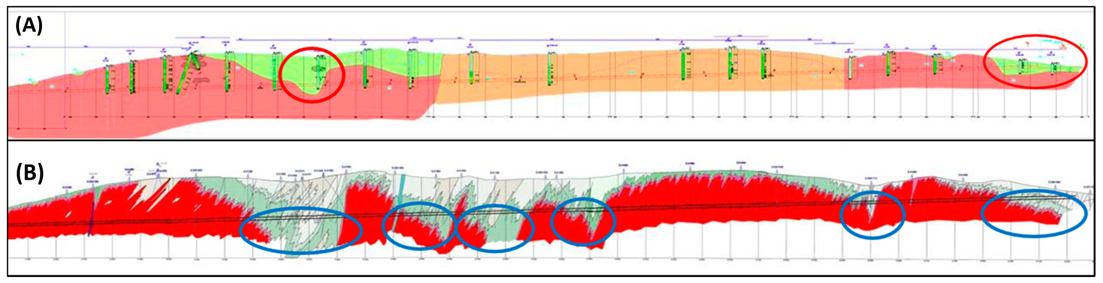
The Burata tunnel was excavated using the drill and blast method, and it has a main tunnel and an additional small parallel tunnel. Its length is approximately 4000 m, and it reaches a maximum depth of approximately 200 m. Its rock mass is composed of granite with differing degrees of alteration. The tunnel was analyzed as a project phase, where the green areas in parts (A) and (B) of Figure 1 correspond to a highly weathered granite residual soil. Part (A) corresponds to the cross-section completed with conventional vertical boreholes, and part (B) shows the real conditions that could be determined using directional core drilling, which detected several additional areas with poor rock mass conditions. The main characteristics and setbacks found in the tunnel have been described by several authors [35,39,40].
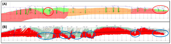
Figure 1.
The Burata tunnel’s geological cross-sections obtained using conventional vertical drilling (A) and directional drilling (B).
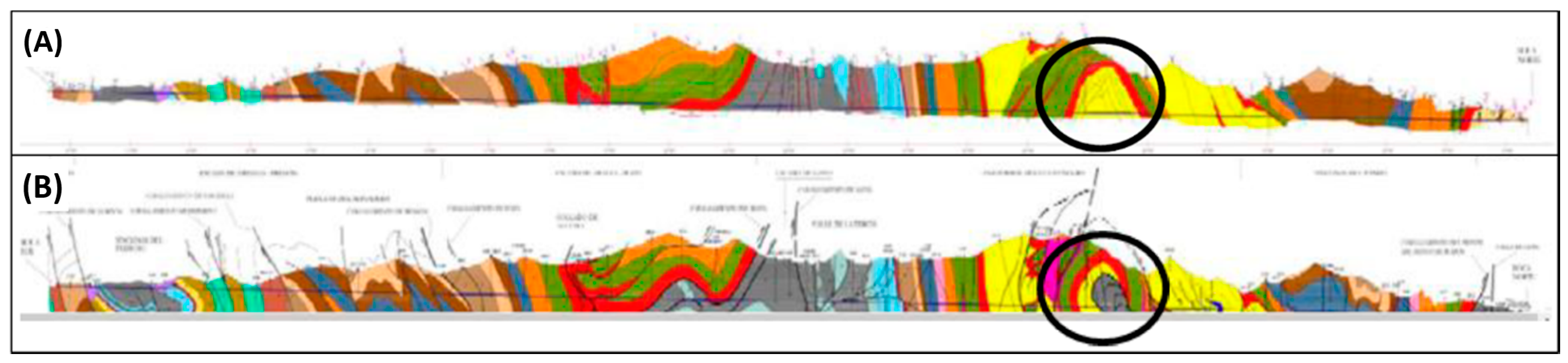
Lot 3 of the Pajares variant is a single tunnel of 10 km in length that is part of the total infrastructure of a twin tunnel of 23 km in length. A single shield TBM with a 10 m diameter was used for the excavation. The maximum depth is approximately 1000 m, and mainly sedimentary rocks were excavated. This study focused on a stretch with potential squeezing conditions and methane emissions. The tunnel was analyzed as a project phase, using real data from the excavation process. Figure 2 presents the initial geological cross-section (A) and the real cross-section once the tunnel was complete (B). As can be seen, there was a formation not detected through the initial vertical drilling campaign. The geology of the Pajares variant tunnels was well-described by Alonso and Rubio [41], who analyzed the area marked in Figure 2. This particular stretch of the tunnel, called the San Emiliano formation, presented singular stability problems [42,43].
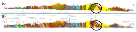
Figure 2.
Geological cross-section of the Pajares variant Lot 3 tunnel.
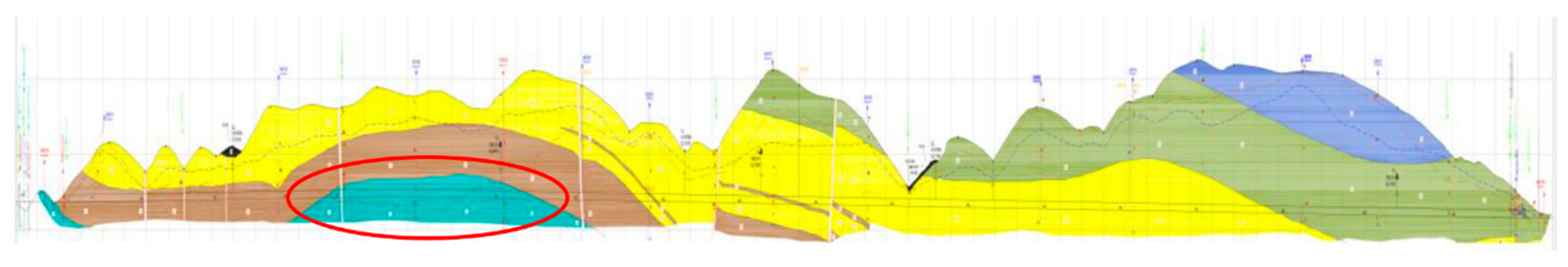
The Bolaños tunnel has a 10 m diameter and is a twin tunnel, though we analyzed only one of them in this study. The analyzed tunnel was excavated using a single-shield TBM. The length of the tunnel is approximately 7000 m, and it has a depth of approximately 200 m. The rock mass consists of slates, quartzites, and sandstones (Figure 3). The study was focused on an area with faults and special requirements for waste management, which can affect the advancement and management of the excavation process.

Figure 3.
Geological cross-section of the Bolaños tunnel.
DCD Technique
The DCD technique can be used in petroleum and mineral explorations, as well as tunnel projects. One of its typical uses is side-tracking drilling for investigating a certain subsurface region, directing the drill string according to the planned trajectory required in the project. In addition, multiple branches of drill holes can be created, extending out from a single primary hole drilled from one position. The principle of the system has three components: (1) planning the drilling trajectory required with the bending and roll angles required; (2) steerable drilling with a control system to obtain the drilling direction and curvature trajectory; and (3) coring orientation surveying using an electronic multishot system (EMS) to record the inclination and azimuth along the drill hole, verifying the planned trajectory and correcting it if necessary [31,32].
3. Methodology for the Uncertainty Economic Valuation
In this study, uncertainty was defined as the difference between the cost of a part of a tunnel’s construction when some variables were unknown and the costs when they were known due to the application of a better technique. Uncertainty was always considered undesirable, and the cost was either higher or lower than initially assessed. If the project cost was higher than the actual final cost, then the developer of the infrastructure—usually the public sector—could waste large amounts of economic resources and the construction company could reach a bankruptcy situation if the initial costs estimated were lower than the actual value. In both cases, society as a whole is negatively affected.
Thus, an approach was proposed for analyzing the costs associated with uncertainty when two drilling techniques—conventional boreholes and directional core drilling—were used during the exploration phase. We determined the costs when using both systems and the lengths of the tunnel recognized with each one. Subsequently, an economic valuation of the uncertainty that existed when using both systems was completed to assess the cost overruns estimated during the exploration phase for both options and the main aspects influenced by a better understanding of the ground conditions. In addition, a comparative analysis was completed to economically assess the uncertainty when using each drilling system. The calculations were based on real average costs from Spain in 2020.
The economic quantification of uncertainty during the exploration and ground characterization phase does not mean that this quantity of money will be saved during the construction phase. In general, the cost during the construction phase will be the same because it is fixed by the ground characteristics. However, it implies that the real cost will be estimated more accurately and known in advance, which will allow for better developing the project, and this will be positive for tunnel construction.
It cannot be considered that all cost overruns and impacts arising from unfavorable site conditions can be prevented if DCD is adopted. The use of DCD can lead to the adoption of mitigation strategies that can reduce both these cost overruns and adverse impacts but it will not entirely eliminate them.
3.1. Borehole Costs
The cost determination of a borehole can be completed using Equation (1), which applies to conventional and DCD techniques, as follows:
where Cb is the total borehole cost (EUR), Cb0 is the transportation and preparation cost of the drilling equipment (EUR), Cb is the linear drilling cost (EUR/m), and Lb is the borehole length (m).
The costs for transportation and preparation were the same for both drilling alternatives, with an average price of approximately EUR 3000, while the cost per meter drilled was approximately EUR 100 per m for conventional drilling and EUR 200 per m for the DCD technique. This difference per meter drilled was because of the additional equipment required for directional drilling, which had an average rental price of EUR 100,000 per month and a drilling yield of 1000 m per month. In addition, it was considered that each vertical borehole obtained information for a 20 m length of the tunnel (10 m for each side), while the DCD technique obtained information for the whole length of the tunnel’s axis.
3.2. Costs Related to Drill and Blast Excavation
Cost overruns are mainly associated with poor rock mass conditions, creating additional costs related to supports, steel, and concrete, as well as working delays.
3.2.1. Support and Lining
A worsening in a rock mass’s quality is related to the need for more robust supports, increasing the use of shotcrete, bolts, ribs, or thicker linings. In this regard, Equation (2) considers the additional costs of support materials:
where Cs is the total cost (EUR), Cst is the price of the steel used for t ribs and rock bolts (EUR/t) (with an average cost of 1750 EUR/t), Cc is the price of concrete (EUR/t) (with an average cost of 85 EUR/t), Mst is the mass of the steel (t), and Mc is the mass of the concrete (t).
The typical supports applied in drill and blast excavations are mainly formed by a combination of three elements (bolting, steel sets, and shotcrete), where the quantities and qualities of these elements define their maximum load capacities [44]. Thus, there are many different combinations of these elements, with some well-known and established recommendations depending on rock mass conditions. In this study, we used the approach established by Romana [45], which is based on the approach proposed by Bieniawski [46].
The property definitions of the materials used in the supports were necessary for the analysis, and we used the parameters defined by Cornejo [47] in the Spanish tunnels studied. For instance, one of the more common material combinations was rebar steel bolts with diameters ranging from 25 to 36 mm and maximum tensile strengths ranging from 482 to 844 kN; concrete with compressive strengths ranging from 25 to 45 MPa; and ribs with a TH profile and a yield strength of 240 MPa.
The mass of the steel and concrete used for a tunnel support can be determined following the procedure detailed by Rodríguez and Pérez [44]. Thus, a simplified procedure for tunnel excavation is proposed using Equations (3) and (4), as follows:
where Mst is the steel used for the support (t), Mc is the concrete used for the support (t), L0 is the initial length of the excavated tunnel (m), Lf is the final length of the excavated tunnel (m), mst is the specific steel consumption (t/m), and mc is the specific concrete consumption (t/m).
Regarding lining usage, the thickness typically applied varies between 35 and 45 cm in most Spanish tunnels, with no variations based on rock mass quality [44]. Therefore, lining was not considered in this analysis.
3.2.2. Performance Decreases and Delays
Quality decreases in a rock mass along a tunnel’s layout result in lower excavation advances, increasing the duration of tunnel construction. Equation (5) defines the advancing rate of a tunnel excavated by drill and blast techniques [44], based on the RMR [46]:
where ab is the advancement per blast (m/blast).
The construction of a tunnel, as with any other economic activity, entails fixed costs, such as salaries, insurance policies, machinery rentals, or fees related to water usage, among many other common factors. Usually, the most important fraction of fixed costs comprises staff salaries, and this cost is considered as the cost of uncertainty associated with duration increases in tunnel construction. Equation (6) defines the number of days required to excavate a tunnel as a function of the number of blasts, and Equation (7) determines its associated fixed costs.
where T is the time required for the tunnel excavation (days), nb is the number of blasts per day (blasts/day), Cf is the total fixed costs for a given period (EUR), and cf is the fixed unit cost (EUR/day). A common daily fixed cost is EUR 12,000.
3.2.3. Special Support Treatments
When rock mass conditions have RMR values that range from 10 to 20 points, it is usually necessary to use micropile umbrellas [45], and the same is true when there is an elastic behavior of ICE < 30 [48]. Thus, the number of micropile umbrellas can be calculated by Equation (8) to define the number of micropiles in each umbrella, and the cost using Equations (9) and (10), respectively, can be also be calculated as follows:
where Np is the number of micropile umbrellas, lm represents the lengths of the micropile umbrellas (m), and ls is the overlap between the micropile umbrellas (m);
where nm is the number of micropiles in each umbrella and nmp is the total number of micropiles; and
where cm is the lineal cost per micropile and Cm is the total cost of the micropile umbrellas.
The typical linear cost of a micropile ranges between 90 EUR/m and 110 EUR/m for drilling diameters of 88.9 mm and 150 mm, respectively.
3.3. Costs Related to the TBM Excavation
The main specific issues in TBM excavations are also caused by unexpected (and not only poorer) rock mass conditions, as in drill and blast, due to much less flexibility in the construction process when using TBMs.
3.3.1. Performance Decreases and Delays
Poor rock mass conditions can lead to increases in excavation times due to poorer excavation performances and squeezing or entrapment, among other issues. Hence, it was necessary to determine the fixed costs using Equation (11). Entrapments can vary considerably in each case, and based on experience from several Spanish tunnels, on average, approximately 30 days is required to restart normal TBM excavations [49].
Here, CfT represents the total fixed costs (EUR), cfT represents the daily fixed costs (EUR/day) (considering 30,000 EUR/day as a mean value for the case studies), T is the time required for the excavation (days), and Te is the time of the entrapment (days).
3.3.2. Support and Lining
The volume of concrete required in a lining segment is defined by Equation (12), and Equation (13) determines the concrete price. On the other hand, the quantity of rebar required and its associated cost can be determined by employing Equations (14) and (15), respectively.
Here, Vh is the concrete volume (m3), De is the external diameter (m), Di is the inner diameter (m), Lf and Lo refer to the stretch of the tunnel analyzed (m), Ch is the total concrete cost (EUR), and ph is the concrete cost (EUR/m3). As references, we took HA-70 with a cost of EUR 219.93 per m3 and HA-45 with a cost of EUR 146.49 per m3.
Here, Ma is the total mass of the steel used in the lining (kg), ma is the mass of the steel per cubic meter of concrete (kg/m3), Ca is the cost of the rebar (EUR), and pa is the unit cost of the rebar (EUR/kg). We considered EUR 0.87 per kg as a reference value.
3.3.3. Cutter Tool Consumption
The number of cutter tools consumed is based on the unit consumption and the volume of rock mass excavated (Equation (16), while its associated cost is included in Equation (17), as follows:
where Nc is the number of cutters consumed (pcs.), cu is the cutter consumption per volume of rock mass excavated (pcs./m3), and VR is the rock mass excavated (m3).
where C is the cost of the cutter tools consumed (EUR), pc is the unit cost (EUR/pcs), and Nc is the number of cutter tools (pcs).
3.4. Costs Related to the Drainage of the Tunnel
The total volume of water extracted from a tunnel is the sum of the different stretches (). Further, additives, such as flocculants or coagulants, are required for its management, as expressed by Equation (18), with an average cost of EUR 0.28 per m3 for the water treatment.
Here, CT is the total cost of the water treatment (EUR), cA is the cost for each cubic meter of water (EUR/m3), and VT is the volume of water extracted (m3).
The average water flow in a tunnel is defined by Equation (19), and the electric power of the water treatment system is calculated by Equation (20), assuming that the power consumption is directly proportional to the amount of water treated.
Here, Qm is the mean water flow (m3/s), Tf is the time required to excavate the tunnel (days), cT is the ratio between the power and the water flow (kW/m3/s) (with a common value of 1000 kW/m3/s), and PT is the total electrical power of the wastewater treatment plant (kW).
In addition, water must be pumped in a tunnel when there is a negative slope in the excavation direction, which requires electrical power that is proportionate to the tunnel length [44]. The mean power required in a stretch from Lo to Lf is defined by Equation (21).
Here, Pw is the pumping power (kW), and cL is the proportion factor. In a tunnel with a negative slope of between 1% and 5%, the value of CL is approximately 0.25 kW/m, and it increases to 0.50 kW/m for negative slopes between 5% and 15%.
Thus, the total energy required for water management is the sum of the water pumping and treatment, assuming that the whole system works 24 h a day (Equation (22)). Equation (23) defines the total energy cost.
Here, E is the overall energy consumption (kWh), Tf is the time required to excavate the tunnel (days), and cE is the energy cost (EUR/kWh), which depends on the type of energy generation. We assumed an energy cost of EUR 0.08 per kWh in this study.
3.5. Costs Related to the Composition of the Material Excavated
The geochemical composition of the material excavated along the tunnel may require different management approaches, such as the construction of landfill sites adequate for the material requirements. Thus, volume must be considered in each scenario, taking into account factors such as over-excavation, bulk factors, and compaction factors. All these elements can increase the cost of tunnel construction (Equation (24)).
Here, CD is the total additional cost for the landfill site, cd0 is the preparation cost of the specific landfill site (EUR) (some typical values for these preparation conditions were found to be approximately EUR 100,000), and cd is the treatment cost of the material disposed of in the landfill site (EUR/m3), which usually ranges between EUR 1 and 5 per m3. We considered the worst-case scenario for the analysis in this study. Further, in Equation (24), VR refers to the volume of the rock or soil excavated (m3).
3.6. Costs Related to the Geological Gas Emissions
The excavation of a tunnel can produce the emission of gasses initially trapped in the rock mass, such as methane, and this is directly linked to the excavation process [21]. These emissions have an environmental impact that must be quantified in the project stage. In the case of methane, it should be transformed into its carbon dioxide equivalent [21,44] for cost determinations (Equation (25)), as follows:
where Cge is the emissions cost (EUR), pCO2 is the price of CO2 emission rights (EUR/tCO2) (the CO2 emission price has varied in recent years from EUR 10 per tCO2 to the current EUR 50 per tCO2), and Eg refers to the equivalent carbon dioxide emissions (tCO2).
3.7. Costs Related to the Use of Special Treatments
In the case of a very weak rock mass, the use of special treatments to consolidate the tunnel face can be necessary to enable the TBM to excavate with an acceptable advancing rate. The total cost of such a treatment can be easily estimated by Equation (26), as follows:
where Cb is the total cost of the resin (EUR) and cb is the unit cost of the treatment per meter of the tunnel (EUR/m).
4. Results
The three case studies were analyzed in terms of economic uncertainty quantification considering the usage of conventional boreholes and DCD. The procedure detailed in Section 3 was used to achieve the results from the different case studies analyzed, and we considered the intrinsic characteristics of each tunnel in the analysis. Further details of the calculations are shown in the Supplementary Material.
4.1. Burata Tunnel
The study of the tunnel’s rock mass conditions was completed using 29 conventional boreholes (27 that were vertical and 2 that were horizontal). Three DCDs would be sufficient, theoretically, to determine the conditions over the whole tunnel length, with one in each portal and the third above the tunnel layout. Table 1 and Table 2 set out the costs of both types of drilling techniques.

Table 1.
Analysis of the conventional approach for the Burata tunnel.
Table 2.
Analysis of the DCD approach for the Burata tunnel.
Considering that each vertical borehole obtains information for a 20 m length of the tunnel and that horizontal boreholes provide information for their equivalent lengths, an investment of EUR 442,500 would determine conditions for 20% of a tunnel’s total length (790 of 4000 m). Thus, the investigation unit cost was EUR 560 per meter of tunnel characterized. Further, 20% of the total cost was related to transport and preparation (not drilling). On the other hand, the DCD approach enables the definition of 100% of the tunnel’s length with an investment of EUR 882,600 and an investigation unit cost of EUR 220 per m, which focused nearly all of the cost on drilling. The conventional technique unit cost was 2.5 times higher than the DCD unit cost.
The economic analysis of the uncertainty related to the tunnel supports was based on actual data from the project. We used data from Romana [45] to define the type of support required (e.g., bolts, steel sets, and shotcrete) and considered the over-excavation based on Innaurato et al. [50] and Mottahedi et al. [51]. Table 3 summarizes the uncertainty costs related to each element that could be found for the Burata tunnel. Average permeabilities of K = 10 − 6 m/s and K = 10 − 7 m/s were considered for the residual soil and granite, respectively.
Table 3.
Uncertainty factors.
Regarding the excavation time, an important variation was found when the time increased from an initial 650 days to 950 days. This increase was caused by a lack of knowledge about the whole tunnel layout, which included a longer length of residual soil conditions instead of granite. Thus, the fixed cost rose incrementally by 46%, reaching EUR 3,600,000.
In this case study, the uncertainty created additional costs for all the factors due to the greater length of the residual soil conditions instead of the granite that was expected initially. Altogether, the associated cost due to uncertainty was EUR 23,808,334, which could have been eliminated by using a DCD technique, with an additional initial cost of EUR 442,100. When the DCD cost is compared to the total cost of the tunnel, at 2.2% of the budget, it remained within an adequate range for a project with complex conditions [52]. Every EUR 1 allocated to DCD usage would have reduced the uncertainty by EUR 54, which was in line with the USNCTT [53], involving an uncertainty reduction of EUR 5952 per m of tunnel excavated. This value was quite relevant since the overall construction cost of the tunnel was EUR 10,000 per m.
4.2. Pajares Variant Lot 3 Tunnel
The study of this specific part of the tunnel layout was completed by using only two conventional boreholes, with a total length of 2050 m drilled. The problems found in drilling the boreholes have been described by Del Olmo and Álvarez [54]. On the other hand, one DCD of 1175 m would have been sufficient, theoretically, to determine the characteristics of the rock mass in the tunnel section studied (Figure 4).
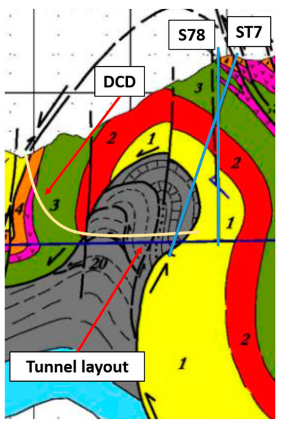
Figure 4.
Area of study in the Lot 3 Pajares variant tunnel.
Table 4 shows the costs of the conventional boreholes and the DCD techniques. The critical area, with a length of 850 m, was called the San Emiliano formation, and two boreholes were drilled (one vertical and one inclined) to define the extension and the characteristics of this formation.
Table 4.
Conventional and DCD techniques analysis for the Parajes variant tunnel.
In this case, a large geological structure needed to be defined. Assuming that the conventional drilling provided information about the tunnel between the two boreholes (approximately 250 m of the tunnel’s layout), there was an investigation unit cost of EUR 844 per m. On the other hand, a DCD technique, with the layout exposed in Figure 4, is proposed. It would require 1175 m of directional drilling and would have an investigation unit cost of EUR 377 per m in order to determine 100% of the tunnel’s layout. Thus, the unit cost of the conventional exploration boreholes is approximately 2.2 times higher than the cost of the DCD technique.
The design and manufacture of the precast lining segments was a very relevant challenge, as has been pointed out by several authors [55,56,57]. There was a cost increment related to the lining (EUR 1,004,108) due to rock mass conditions that were worse than initially defined by the conventional drilling, and the cost increased from the planned EUR 4,202,085 to a real cost of EUR 5,206,193.
In addition, the advance of the TBM was unexpectedly reduced from 15 m/day to 6 m/day, according to the real advancing rate data [58,59], increasing the duration of the excavation by 54 days due to a poorer performance, which represented a cost increase of EUR 1,620,000 due to unexpected conditions.
The cutter tools consumption was lower in the real conditions due to less abrasive characteristics [60]. There was an expected consumption of 0.7 pcs/m, and in the real conditions, the consumption was 0.04 pcs/m (595 and 232 cutter tools, respectively). Considering the average cost of a cutter at the time of the tunnel’s construction (EUR 2500 per piece), EUR 907,500 was saved.
The risks of entrapment and gas emissions were other potential setbacks that did not occur, despite that they were prone to occur in the actual geological conditions found, and therefore, they must be counted in the global assessment of the project [42,43]. The potential entrapment, with an average of 30 days, would have a total fixed cost of EUR 900,000. The geological formation could also contain methane (CH4), with a potential emission of approximately 11 m3 of methane for every ton of material excavated, based on previous studies [21], with a total of 1,562,000 m3 of CH4 and, therefore, 25,000 tCO2. Considering the price of each ton of CO2 at the time of the tunnel’s excavation (EUR 14 per t), the associated economic risk related to the methane emissions would be approximately EUR 350,000. Table 5 summarizes the uncertainty costs related to each element that could be found in the tunnel.
Table 5.
Uncertainty factors.
Overall, the use of the DCD technique eliminates a risk of EUR 4,781,608, which is EUR 5625 per m of tunnel excavated in the stretch analyzed and equivalent to EUR 14.9 for every EUR 1 invested in DCD. This value was approximately 25% of the total excavation cost per meter, which would assume a very high risk if the stretch was not well-defined.
4.3. Bolaños Tunnel
There was a region in the Bolaños Tunnel with a potential length of nearly 1000 m that required detailed definition of the rock mass characteristics during the excavation stage of the tunnel. In this regard, five vertical boreholes were drilled in the study area. Table 6 sets out the cost assessments of the conventional boreholes and the DCD technique for this particular stretch of the tunnel. Based on the same geological cross-section used to define the conventional vertical boreholes, a single DCD was proposed (Figure 1).
Table 6.
Conventional and DCD assessments for the Bolaños tunnel.
The cost distribution for the conventional approach was 16% for transportation and 84% for drilling, resulting in knowledge of only 5% of the tunnel’s layout for the area of interest (investigation unit cost of EUR 940 per m). On the other hand, DCD reached 100% definition of the region, and its costs were concentrated on drilling (investigation unit cost of EUR 323 per m), as it can be seen by the red line in Figure 5. In this case, the conventional technique was nearly three times more expensive than the DCD technique.
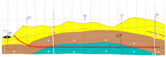
Figure 5.
Layout of the DCD technique proposed for the Bolaños tunnel.
Regarding the geochemical composition of the rock mass, the ampelite slates found in the stretch studied could have generated contamination due to the presence of sulphides and heavy metals. Thus, it was considered the worst-case scenario in the analysis, based on the characteristics defined in Section 3, with a total of EUR 600,000 as an additional cost for the management of the rock mass excavated in the affected area. Moreover, the TBM performance was poorer than planned in the project. The expected rate was 25 m/day, whereas the actual excavation rate was 4 m/day, requiring 22 additional days of excavation, which resulted in an additional cost of EUR 660,000. The presence of a rock mass with squeezing characteristics created an additional risk cost of EUR 900,000.
In the case studied, one of the main points of the construction system was the previous treatment of the unstable excavation face using organo-mineral resins. Thus, the resin consumption was higher and, therefore, more expensive. The tunnel in this case study also faced the risk of squeezing due to the presence of ampelite minerals in the slate formation [61]. The unit cost of the treatment could be estimated at EUR 1260 m under normal conditions, and it reached EUR 4620 per m under the squeezing conditions, with 1000 m of poor conditions faced in the analyzed tunnel. Hence, there was a cost overrun of EUR 3,360,000 due to poor knowledge of the rock mass. Table 7 summarizes the overall uncertainty costs of the tunnel.
Table 7.
Uncertainty factors found in the Bolaños tunnel.
Based on the assessment of the Bolaños tunnel, the DCD technique could have reduced the uncertainty by EUR 5,520,000 in the stretch analyzed (EUR 5520 per m), which represents EUR 6.7 for every EUR 1 invested in DCD.
5. Discussion
The analysis of the three case studies revealed how the use of the DCD technique can help to better characterize rock mass conditions and reduce uncertainty from an economic perspective.
The mean value of the uncertainty in the three tunnels studied was approximately EUR 6000 per m. Thus, an investment of EUR 1 would allow an uncertainty decrease of between EUR 6.7 and EUR 14.9. The unit cost of the conventional borehole technique ranged between two and three times higher than costs related to the DCD option. The total expenditure remained within the recommended cost range defined by Pelizza et al. [62] and several actual projects [63,64], considering the corresponding inflation adjustments.
In contrast to conventional vertical boreholes, the proposed system allows for determining the condition of an entire tunnel layout. The technique could be particularly useful for characterizing shallow tunnels in populated areas, and it could be crucial for defining specific complex areas in deep tunnels. It also allows planners to define the geological domains of a tunnel’s layout, identify the groundwater levels, characterize the geomechanical properties and determine the excavated areas requiring degassing in the future. In addition, DCD can be especially relevant when there is a region of the tunnel’s layout with potential geochemical risks since conventional drilling only permits the extraction of samples from very local regions.
The approach proposed is especially relevant for TBM tunnels since it is an excavation method with little flexibility compared with the drill and blast method, and requires important knowledge about the rock mass characteristics to avoid unexpected conditions. These situations are noted in the setbacks experienced in the Bolaños and Pajares variant tunnels, where the uncertainties caused deviations in the lining, cutter tools consumption, waste management, and TBM performance. Among the limitations of the study, the TBM entrapment was analyzed considering only the fixed cost, and there could have been additional costs related to repairs or additional equipment required for the procedure.
In addition, the employment of the directional core drilling technique reduces the number of drillings required, and consequently, it also reduces the environmental impact due to a smaller surface being affected. Despite this, such factors have not been quantified, and it is an important component to consider as it could help in the administration of the procedure and with interactions with the inhabitants of such areas. However, health and safety implications for tunnel personnel, such as gas emissions, were kept out of the analysis. Only some uncertainties that were easy to evaluate economically were considered, and the methodology could be extended to other uncertainties with other associated cost overruns.
6. Conclusions
The approach proposed can be used to assess the economic impact of the geological uncertainty inherent in the excavation of a tunnel, considering the main factors in the TBM and drill and blast excavation methods. The system could be especially useful in a future tunnel or area with high probabilities of poor rock mass conditions or other potential anomalies. Three real case studies were analyzed in detail with the method detailed, considering the initial and actual conditions found in the tunnel construction phases.
The use of the directional core drilling technique generally involves higher costs than those related to conventional boreholes, but it has the advantage that information is obtained from the entire length of the investigated tunnel section, and it can be useful from geological, geotechnical, and hydrogeological perspectives. This technique allows planners to define the factors that may create uncertainty in terms of time and cost. In addition, the cost of applying the technique would remain at approximately 2% of a tunnel’s execution budget, which is reasonable in geological and geotechnical research campaigns.
Supplementary Materials
The following supporting information can be downloaded at: https://www.mdpi.com/article/10.3390/app131910998/s1.
Author Contributions
Conceptualization, R.R. and V.F.; methodology, R.R., V.F. and M.B.; validation, R.R., V.F., H.G.-G. and M.B.; investigation, R.R., V.F. and M.B.; data curation, R.R., V.F., H.G.-G. and M.B.; writing—original draft preparation, R.R. and M.B.; writing—review and editing, R.R., V.F., H.G.-G. and M.B.; supervision, R.R. All authors have read and agreed to the published version of the manuscript.
Funding
This research received no external funding.
Institutional Review Board Statement
Not applicable.
Informed Consent Statement
Not applicable.
Data Availability Statement
No new data were created or analyzed in this study. Data sharing is not applicable to this article.
Acknowledgments
The authors would like to thank the technical staff of the tunnels studied; in particular, they would like to thank E. Castells (for the Burata tunnel), A. Tosal and C. Lombardía (for the Pajares variant Lot 3 tunnel), and J. Margareto and E. González for the Bolaños tunnel.
Conflicts of Interest
The authors declare no conflict of interest.
References
- Estefanía, C.; Fuldain, J.A.; Laguna, J.A.; Arlandi, M. Payment for Tunnel Construction by Means of the Standard Rate Method: Experience on the Bilbao South Metropolitan By-Pass; Association Canadian Tunnels ACT: Toronto, ON, Canada, 2010; pp. 12–26. [Google Scholar]
- Benardos, A.; Paraskevopoulou, C.; Diederichs, M. Assessing and benchmarking the construction cost of tunnels. In Proceedings of the 66th Canadian Geotechnical Conference, GeoMontreal on Geoscience for Sustainability, Montréal, QC, Canada, 29 September–3 October 2013. [Google Scholar]
- Membah, J.; Asa, E. Estimating cost for transportation tunnel projects: A systematic literature review. Int. J. Constr. Manag. 2015, 15, 196–218. [Google Scholar] [CrossRef]
- Zhao, J.; Liu, Q.; Lee, K.W.; Choa, V.; Teh, C.I. Underground cavern development in the Jurong sedimentary rock formation. Tunn. Undergr. Space Technol. 1999, 14, 449–459. [Google Scholar] [CrossRef]
- Sinfield, J.V.; Einstein, H.H. Tunnel construction costs for tube transportation systems. J. Constr. Eng. Manag. 1997, 124, 48–57. [Google Scholar] [CrossRef]
- Hoek, E. Big tunnels in bad rock. J. Geotech. Geoenvironmental Eng. 2001, 127, 726–740. [Google Scholar] [CrossRef]
- Flyvbjerg, B.; Bruzelius, N.; van Wee, B. Comparison of capital costs per route-kilometre in urban rail. Eur. J. Transp. Infrastruct. Res. 2008, 8, 17–30. [Google Scholar]
- Flyvbjerg, Β.; Holm, M.S.; Buhl, S.L. What Causes Cost Overrun in Transport Infrastructure Projects? Transp. Rev. 2004, 24, 3–18. [Google Scholar] [CrossRef]
- Isaksson, T.; Stille, H. Model for estimation of time and cost for tunnel projects based on risk evaluation. Rock Mech. Rock Eng. 2005, 38, 373–398. [Google Scholar] [CrossRef]
- Petroutsatou, C.; Lambropoulos, S. Quick cost pre-estimation of road tunnels. In Proceedings of the 2nd Hellenic Congress of Roads, Technical Chamber of Greece, Volos, Greece, 18–20 May 2005. [Google Scholar]
- Efron, N.; Read, M. Analysing International Tunnel Costs: An Interactive Qualifying Project Report; Worcester Polytechnic Institute: Worcester, MA, USA, 2012. [Google Scholar]
- Rostami, J.; Sepehrmanesh, M.; Gharahbagh, E.A.; Mojtabai, N. Planning level tunnel cost estimation based on statistical analysis of historical data. Tunn. Undergr. Space Technol. 2013, 33, 22–33. [Google Scholar] [CrossRef]
- Yau, K.; Paraskevopoulou, C.; Konstantis, S. Spatial variability of karst and effect on tunnel lining and water inflow. A probabilistic approach. Tunn. Undergr. Space Technol. J. 2020, 97, 103248. [Google Scholar] [CrossRef]
- Paraskevopoulou, C.; Benardos, A. Assessing the construction cost of tunnel projects. Tunn. Undergr. Space Technol. 2013, 38, 497–505. [Google Scholar] [CrossRef]
- Petroutsatou, K.; Georgopoulos, E.; Lambropoulos, S.; Pantouvakis, J.P. Early cost estimating of road tunnel construction using neural networks. J. Constr. Eng. Manag. 2012, 138, 679–687. [Google Scholar] [CrossRef]
- Petroutsatou, K.; Maravas, A.; Saramourtsis, A. A lifecycle model for estimating road tunnel cost. Tunn. Undergr. Space Technol. 2021, 111, 103858. [Google Scholar] [CrossRef]
- Karkehabadi, V.; Zarei, H.; Uromeihy, A.; Karkehabadi, H. Investigating the economic performance of tunnel excavation in iran: 1998–2013. Geotech. Geol. Eng. 2014, 32, 1353–1362. [Google Scholar] [CrossRef]
- Hasanpour, R.; Rostami, J.; Barla, G. Impact of advance rate on entrapment risk of a double-shielded TBM in squeezing ground. Rock Mech. Rock Eng. 2015, 48, 1115–1130. [Google Scholar] [CrossRef]
- Yu, J.; Zhong, D.; Ren, B.; Tong, D.; Hong, K. Probabilistic risk analysis of diversion tunnel construction simulation. Comput. Aided Civ. Infrastruct. Eng. 2017, 32, 748–771. [Google Scholar] [CrossRef]
- Rodríguez, R.; Díaz-Aguado, M.B. Environmental impact due to tunnels excavation: A key aspect for its success. Experiences in Asturias (Northern Spain). In Proceedings of the AFTES International Congress “Underground Spaces for tomorrow”, Lyon, France, 17–19 October 2011. [Google Scholar]
- Rodríguez, R.; Díaz-Aguado, M.B.; Lombardía, C. Compensation of CH 4 emissions during tunneling works in Asturias: A proposal with benefits both for local councils and for the affected population. J. Environ. Manag. 2012, 104, 175–185. [Google Scholar] [CrossRef]
- Paraskevopoulou, C. Cost Analysis of Greek Road Tunnels. Diploma Thesis, National Technical University of Athens, Athens, Greece, 2011. [Google Scholar]
- Langford, J.C.; Diederichs, M.S. Support design for excavations in brittle rock using a Global Response Surface Method. Rock Mech. Rock Eng. 2014, 48, 669–689. [Google Scholar] [CrossRef]
- Paraskevopoulou, C.; Boutsis, G. Cost overruns in tunnelling projects: Investigating the impact of geological and geotechnical uncertainty using case studies. Infrastructures 2020, 5, 73. [Google Scholar] [CrossRef]
- Dowdell, R.; Kaplin, J.; Tokle, V. Directional core drilling used to explore rock conditions for a water supply tunnel: Challenges for the 21st Century. In Proceedings of the World Tunnel Congress ‘99, Oslo, Norway, 2 June 1999; pp. 51–59. [Google Scholar]
- Shinmoto, Y.; Miyazaki, E.; Wada, K.; Yamao, M. Development of a continuous directional coring system for deep-sea drilling. SPE Drill. Complet. 2012, 27, 139–144. [Google Scholar] [CrossRef]
- Cao, X.; Kozhevnykov, A.; Dreus, A.; Liu, B. Diamond core drilling process using intermittent flushing mode. Arab. J. Geosci. 2019, 12, 137. [Google Scholar] [CrossRef]
- Moelle, K.H.R.; Young, J.D. On geological and technological aspects of oriented n-size core diamond drilling. Eng. Geol. 1970, 4, 65–72. [Google Scholar] [CrossRef]
- Jura, B.; Skiba, J.; Wierzbinski, K. Applicability of surface directional wells for upper silesia basin coal seams’ drainage ahead of mining. Int. J. Min. Sci. Technol. 2014, 24, 353–362. [Google Scholar] [CrossRef]
- Lindhjem, R.; Tai, C. Directional core drilling in geotechnical exploration In Underground Facilities for Better Environment and Safety. In Proceedings of the World Tunnel Congress, Agra, India, 19–25 September 2008. [Google Scholar]
- Cunningham, B.; Tam, J.K.W.; Tattersall, J.W.; Seit, R.K.F. Horizontal Directional Coring (HDC) and Groundwater Inflow Testing for Deep Subsea Tunnels. In Proceedings of the HKIE Geotechnical Division 32 Annual Seminar—Geotechnical Aspects of Tunnelling for Infrastructure, Hong Kong, 25 May 2012. [Google Scholar]
- Cunningham, B.; Tam, J.K.W.; Tattersall, J.W.; Nip, G.C.Y.; Seit, R.K.F. Planning of Horizontal Directional Coring for Deep Subsea Tunnel. In Proceedings of the HKIE Civil Division International Conference—Innovation and Creativity of Infrastructure Development for Quality Cities, Kowloon, Hong Kong, 26–28 April 2012. [Google Scholar]
- Wang, F.; Ren, T.; Tu, S.; Hungerford, F.; Aziz, N. Implementation of underground longhole directional drilling technology for greenhouse gas mitigation in Chinese coal mines. Int. J. Greenh. Gas Control 2012, 11, 290–303. [Google Scholar] [CrossRef]
- Boden, A.; Bridges, G.; Tsang, C.K.; Zu, J. Experience of horizontal direction coring in Hong Kong. Proc. Inst. Civ. Eng. Civ. Eng. 2018, 171, 179–185. [Google Scholar]
- Castells, E. Aplicación de sondeos horizontales para determinar las características del terreno antes o durante la excavación del túnel. Sistemas de medición de desviación de sondeos. Ingeopres 2008, 170, 22–26. [Google Scholar]
- Tsang, C.K.; Chau, S.F.; Chan, J. Subsea horizontal directional coring (HDC). Geotech. Eng. J. 2015, 47, 31–36. [Google Scholar]
- Shi, J.W.; Ng, C.W.W.; Chen, Y. A simplified method to estimate three-dimensional tunnel responses to basement excavation. Tunn. Undergr. Space Technol. 2017, 62, 53–63. [Google Scholar] [CrossRef]
- Zheng, G.; Yang, X.; Zhou, H.; Du, Y.; Sun, J.; Yu, X. A simplified prediction method for evaluating tunnel displacement induced by laterally adjacent excavations. Comput. Geotech. 2018, 95, 119–128. [Google Scholar] [CrossRef]
- López-Fernández, C.; Arias, D.; Fernández-Viejo, G.; Pando, L.; Castells, E. Surface Subsidence Induced by Groundwater Drainage Tunneling in Granite Residual Soils (Burata Railway Tunnel, Spain). J. Geotech. Geoenvironmental Eng. 2013, 139, 821–824. [Google Scholar] [CrossRef]
- Castells, E.; Perea, J.L.; Bujalance, F.; Varela, F. Túnel de Formigueiro y Túnel de Burata. Ingeopres 2006, 154, 44–49. [Google Scholar]
- Alonso, J.L.; Rubio, A. La estructura geològica de la sección del Túnel de Pajares. In Jornadas Técnicas de la Variante de Pajares; Pando, L., López Fernández, C., De la Rubia Mir, L., Eds.; ADIF—Universidad de Oviedo: Oviedo, Spain, 2009; pp. 29–39. [Google Scholar]
- García de Muro, J. Lote 3: Excavación en lutitas y pizarras carbonosas de San Emiliano. In Jornadas Técnicas, Variante de Pajares; Pando, L., López Fernández, C., De la Rubia Mir, L., Eds.; ADIF—Universidad de Oviedo: Oviedo, Spain, 2009; pp. 181–190. [Google Scholar]
- Díaz-Aguado, M.B.; García de Muro, J.; Rodríguez, R. Main difficulties and lessons learnt during the TBM excavation in shales in the North portal of Pajares tunnels. In Proceedings of the ISRM Regional Symposium—EUROCK 2014, Vigo, Spain, 27–29 May 2014; Alejano, R., Perucho, Á, Olalla, C., Jiménez, R., Eds.; Taylor & Francis: London, UK, 2014. [Google Scholar]
- Rodríguez, R.; Pérez, F. Carbon foot print evaluation in tunneling construction using conventional methods. Tunn. Undergr. Space Technol. 2021, 108, 103704. [Google Scholar] [CrossRef]
- Romana, M. Update of 1989 Bieniawski’s RMR guidelines for tunnel excavation and support. In Proceedings of the ISRM European Regional Symposium—EUROCK 2014, Vigo, Spain, 27–29 May 2014; pp. 1139–1144. [Google Scholar] [CrossRef]
- Bieniawski, Z.T. Engineering Rock Mass Classifications: A Complete Manual for Engineers and Geologists in Mining, Civil, and Petroleum Engineering; John Wiley & Sons: Hoboken, NJ, USA, 1989. [Google Scholar]
- Cornejo Álvarez, L. Nuevas Tendencias en los Revestimientos de Túneles. In Ingeniería de Túneles, 13th ed.; Proyectos—Universidad Politécnica de Madrid: Madrid, Spain, 2007. [Google Scholar]
- Celada, T.; Fernández, P.M.; Rodríguez, A.; Tardáguila, V.I. Definición Preliminar de las Secciones Tipo de Sostenimiento en Túneles Proyectados por Métodos Convencionales. Ingeopres 2010, 192, 16–22. [Google Scholar]
- Abascal, A.; Auvray, J.M. Atrapamiento de Escudo de Cola en la Formación Formigoso. Túneles de Pajares; ADIF: Madrid, Spain, 2009; pp. 509–524. [Google Scholar]
- Innaurato, N.; Mancini, R.; Cardu, M. On the influence of rock mass quality on the quality of blasting work in tunnel driving. Tunn. Undergr. Space Technol. 1998, 13, 81–89. [Google Scholar] [CrossRef]
- Mottahedi, A.; Sereshki, F.; Ataei, M. Development of overbreak prediction models in drill and blast tunneling using soft computing methods. Eng. Comput. 2018, 34, 45–58. [Google Scholar] [CrossRef]
- Ayhan, M.; Aydın, D.; Şefik, M.; Imamoglu, M.S.; Cogalan, M.; Karakus, A. Investigation of a methane flare during the excavation of the Silvan irrigation tunnel, Turkey. Bull. Eng. Geol. Environ. 2018, 78, 2641–2652. [Google Scholar] [CrossRef]
- U.S. National Committee on Tunnelling Technology (USNCTT). Geotechnical Site Investigations for Underground Projects; National Academy of Engineering: Washington, DC, USA, 1984. [Google Scholar]
- Del Olmo, J.; Álvarez, J.R. Ensayos Geológicos de Investigación a Grandes Profundidades. Variante de Pajares; Pando, L., López Fernández, C., De la Rubia Mir, L., Eds.; ADIF—Universidad de Oviedo: Oviedo, Spain, 2009; pp. 19–28. [Google Scholar]
- Segura, P.; Martínez, J.F. Hormigones de Alta Resistencia en El Tramo II del Túnel de Pajares. Túneles de Pajares; ADIF: Madrid, Spain, 2009; pp. 35–50. [Google Scholar]
- Méndez, L.A.; Rabadán, P.; Sedano, F. Fabricación de hormigones de alta resistencia para dovelas. In Jornadas Técnicas, Variante de Pajares; Pando, L., López Fernández, C., De la Rubia Mir, L., Eds.; ADIF—Universidad de Oviedo: Oviedo, Spain, 2009; pp. 237–245. [Google Scholar]
- Torbado, S. Planta de dovelas: Definición, instalaciones, proceso de fabricación, materiales y producción. In Jornadas Técnicas, Variante de Pajares; Pando, L., López Fernández, C., De la Rubia Mir, L., Eds.; ADIF—Universidad de Oviedo: Oviedo, Spain, 2009; pp. 229–236. [Google Scholar]
- Camus, T.; Fontanille, G.; Champeaux, J.L.; Margareto, J.; Fajardo, F. Single shield TBM performance in Carboniferous rock. The case study of Pajares-Sotiello. In Proceedings of the AFTES International Congress, Lyon, France, 17–19 October 2011. [Google Scholar]
- Mendaña, F.; Fernández, R. Tuneladoras en Pajares. In Túneles de Pajares; ADIF: Madrid, Spain, 2009; pp. 127–152. [Google Scholar]
- Abascal-Aznar, A. Herramientas de corte en TBM para roca dura. Consumo de cortadores por formación geológica. In Jornadas Técnicas de la Variante de Pajares; Pando, L., López Fernández, C., De la Rubia Mir, L., Eds.; ADIF—Universidad de Oviedo: Oviedo, Spain, 2009; pp. 173–179. [Google Scholar]
- Mendaña, F. Túneles de Bolaños. Estabilización de zonas de falla con resinas y relleno con bicomponente inyectado a presión del trasdós del revestimiento de anillos de dovelas en un escudo simple para roca dura. Obras Públicas 2017, 3590, 46–67. [Google Scholar]
- Pelizza, S.; Peila, D.; Oreste, P.P.; Oggeri, C.; Vinai, R. Environmental aspects of underground construction and exploration for underground structures. In Proceedings of the ACUUS 2002 International Conference, Torino, Italy, 14–16 November 2002. [Google Scholar]
- Barla, G.; Pelizza, S. TBM Tunnelling in Difficult Ground Conditions. In Proceedings of the GEOENG 2000, Melbourne, Australia, 19–24 November 2000. [Google Scholar]
- Castello, G.; Chantron, L.; Fabre, D.; Sem, M. Analysis of the TBM Performances for the Excavation of the Trasvase Guadiaro-Majaceite, Province of Cadiz, Spain. In Proceedings of the ITA World Tunnel Congress, Oslo, Norway, 29 May–3 June 1999; Volume 9. [Google Scholar]


Disclaimer/Publisher’s Note: The statements, opinions and data contained in all publications are solely those of the individual author(s) and contributor(s) and not of MDPI and/or the editor(s). MDPI and/or the editor(s) disclaim responsibility for any injury to people or property resulting from any ideas, methods, instructions or products referred to in the content. |
© 2023 by the authors. Licensee MDPI, Basel, Switzerland. This article is an open access article distributed under the terms and conditions of the Creative Commons Attribution (CC BY) license (https://creativecommons.org/licenses/by/4.0/).