Article

Strength Analysis of an Open Car Body with Honeycomb Elements during Ro-Ro Transportation

1
Department of Transport and Handling Machines, Faculty of Mechanical Engineering, University of Žilina, Univerzitná 1, 010 26 Žilina, Slovakia
2
Department of Cars and Carriage Facilities, Faculty of Infrastructure and Rolling Stock of Railways, State University of Infrastructure and Technologies, Kyrylivska Street, 9, 04071 Kyiv, Ukraine
*
Author to whom correspondence should be addressed.
Appl. Sci. 2023, 13(19), 11022; https://doi.org/10.3390/app131911022
Submission received: 30 June 2023 / Revised: 29 September 2023 / Accepted: 5 October 2023 / Published: 6 October 2023
(This article belongs to the Special Issue Railway Dynamic Simulation: Recent Advances and Perspective)

Abstract

:
This article presents the determination of the bearing structure loads of an open car during ro-ro transportation. A special solution for an open car is the application of elastic, viscous honeycomb panels in the frame. This engineering solution can decrease the load of the bearing structure of an open car during interactions with multiple-use lashing devices. This article presents the mathematic modelling of the dynamic load of an open car during ro-ro transportation. This calculation is based on the most popular load diagrams for the bearing structure of an open car applied for sea transportation, namely the rolling motion and the turning motion of a train ferry approaching a dock. It was found that the application of honeycomb panels can decrease the dynamic load of a rail car in comparison to a standard structure by about 25%. The results of the strength calculation of the bearing structure of an open car demonstrated that the maximum equivalent stresses do not exceed the allowable values and are 30% lower than the stresses that emerging in the standard structure. The conducted research can be used by engineers who are concerned about safe and environmentally friendly transportation via train ferries and more efficient ro-ro transportation.

1. Introduction

The evolving international economic relations between European and Asian countries indicate the need to improve the operational efficiency of the transport industry. This can be achieved through the introduction of combined transport systems (Figure 1), and one of the most promising of them is ro-ro transportation [1,2].
The world’s first ro-ro service was launched in 1851; it operated across the Firth of Forth from Granton to Burntisland [3]. At present, the ro-ro route map is popular. This type of combined transportation has been constantly developing; it is used not only across seas, but also across rivers, lakes, and even oceans.
It should be noted that safe and environmentally friendly transportation via train ferries can only be provided through the technical customization of rail cars for sea transportation. The standards for designing and calculating rolling stock should primarily include the load characteristics of the rail cars transported via train ferries. However, these cars are vulnerable to damage to bearing structures, which requires additional maintenance charges due to out-of-schedule repairs. In addition, failures in the fixation of rail cars on the deck lead to the instability of the train ferry; moreover, they may cause an ecological danger. Due to the unreliable fastening of a tank car on a deck, the train ferry Mercury-2 crashed during a storm in the Caspian Sea. Its sixteen tank cars with oil products sank in the sea. Another accident happened in the Mediterranean Sea with the Greek ferry, Heraklion, which sank due to the unreliable fastening of vehicles on its deck during a storm.
Therefore, the determination of the load of cars during sea transportation, their technical customization for interactions with lashing devices on the deck, and improvements to the standards for designing and calculating the bearing structures of rail cars are urgent and foremost problems requiring thorough investigation.
The improvements to the bearing structure of an open car via computer modelling are grounded in [4]. The authors describe the reasons for failures in the most loaded areas of the frame and suggest some measures for their prevention. The results of the strength calculation for an improved open car frame proved the effectiveness of the implemented measures.
The reasons for defects in the bearing structure of an Sgmns car (four-axis multimodal car) were studied in [5]. The authors suggested some measures to reinforce the most loaded areas of the rail car frame and substantiated the need to improve the frame.
However, while considering the reasons for crack developments, the authors did not consider the potential loads on the bearing structure of a car transported via a train ferry.
The authors of [6] present a comparative analysis of the results of the static strength of the bearing structure of an Sdggmrss-twin car (six-axis freight car for the transportation of trailers) using theoretical and experimental methods for strength calculation. The authors explained the prospects of further improvement to the proposed car structure. However, the car structure had no fixation units on the deck, which can cause damage to the car’s bearing structure during sea transportation.
A technique used to improve the strength calculation for the components of the bearing structure of an open car is described in [7]. The authors determined the load of the bearing structure of a car during operational modes and suggested a way to improve the standards for designing and calculating rail cars. However, the determination of the load and the improvement in the bearing structure of a car transported via sea were not presented.
The locational optimization of the centre of gravity of a rail car to improve the rotation characteristics is described in [8]. The authors suggested a technique for data analysis to improve the dynamic load of a rail car in operation relative to the rail track. However, they did not determine the dynamic load of the rail car during the turning motion of a train ferry approaching a dock.
The peculiarities of determining the inertia moments of freight car bodies are described in [9]. The technique suggested for the determination of the inertia characteristics of rail cars may be used for theoretical research into the dynamic load of rail cars. However, the study did not give any practical applications of the technique in operational load modes.
The authors of [10,11] studied the determination of the load on the bearing structure of a rail car transported via a train ferry. They suggested some measures to improve the interaction diagram between the bearing structure and the deck. They substantiated the application of a viscous connection to reduce the dynamic load of the bearing structure of a rail car transported via sea. However, the load of the bearing structure of a rail car during the turning motion of a train ferry approaching a dock was not considered.
Other publications [12,13,14] describe the prospects of the development of combined transport, including sea transport. The requirements for ensuring the safe operation of combined transport were formulated. At the same time, the authors did not pay attention to the issues of reducing the dynamic loading of vehicles transported via train ferries. Moreover, the shipbuilding regulations of the Classification Societies (IACS) do not include the possibility of adapting the load-bearing structure of a vehicle, in particular, a wagon, for its safe transportation via train ferries. This necessitates research into the adaptation of wagons for sea transportation.
The purpose of this article is to present the results and describe the special features of determining the load on the bearing structure of an open car with elastic, viscous honeycomb elements during over-normative load modes (the least favourable conditions of sea disturbance and the turning motion of a train ferry approaching a dock). To achieve this purpose, the following objectives were defined:
  • To develop measures to improve the bearing structure of an open car for safe transportation via a train ferry;
  • To determine the load on the bearing structure of an open car during rolling motions;
  • To determine the load on the bearing structure of an open car during the turning motions of a train ferry;
  • To investigate the strength of the bearing structure of an open car transported via a train ferry.

2. Methods and the Data

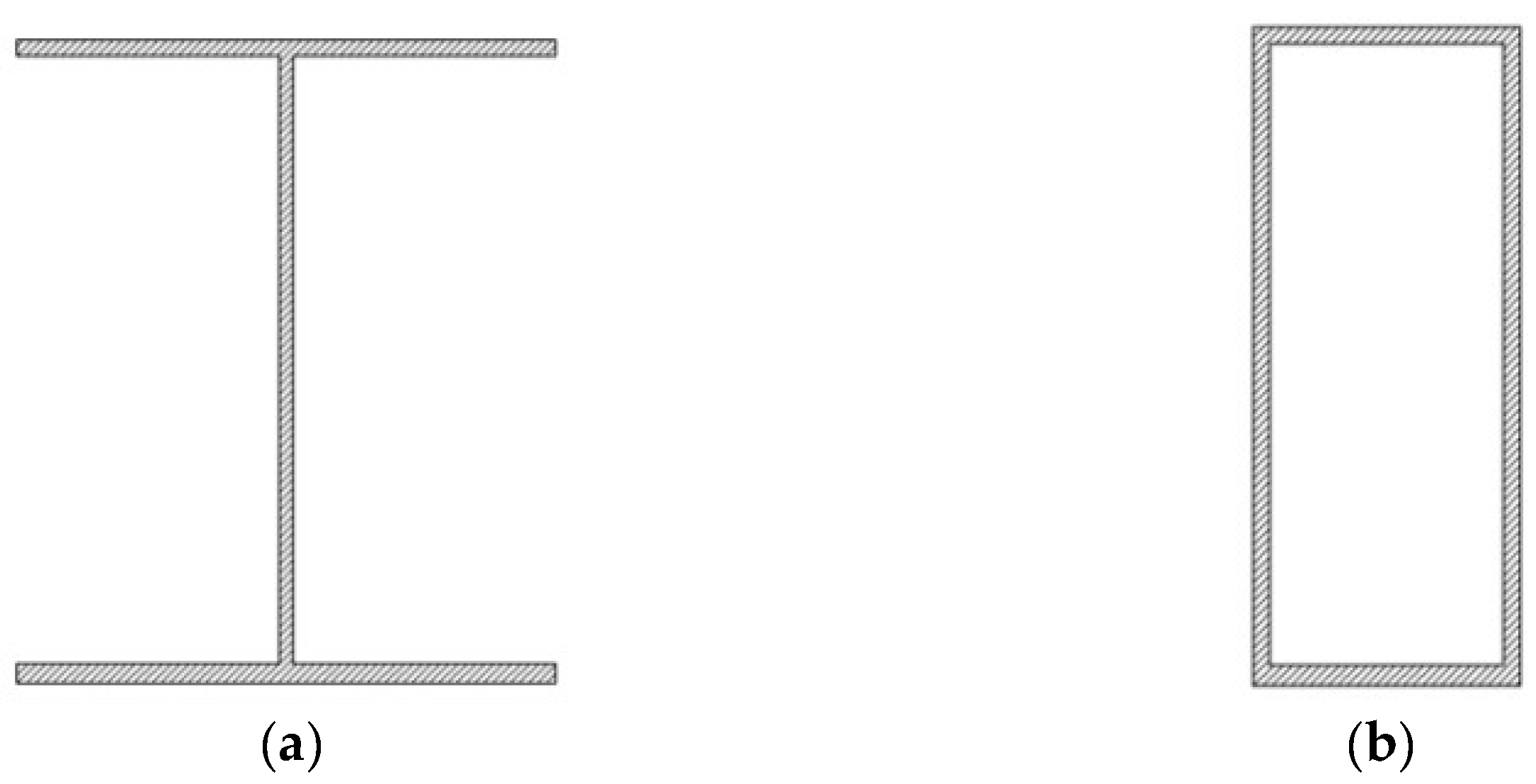
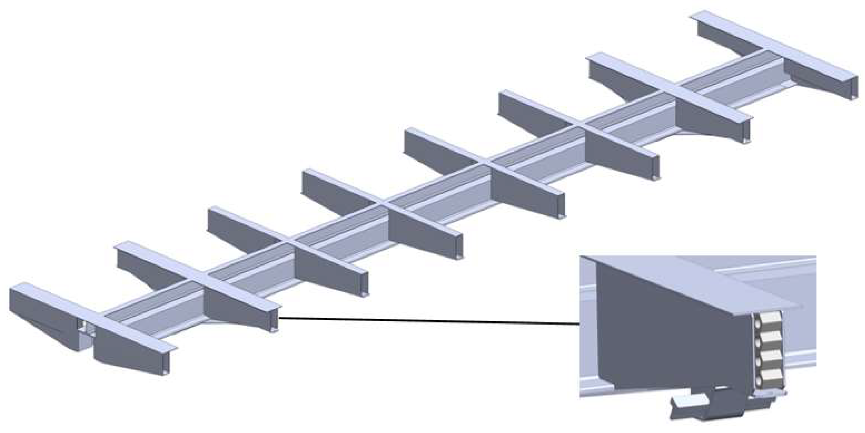
The dynamic load on the bearing structure of an open car at operational load modes can be reduced through some improvements. One of them is the application of elastic, viscous honeycomb panels between the vertical sheets of the intermediate, end, and bolster beams; the intermediate beams are made of a boxed section (Figure 2 and Figure 3).
The proposed solution was substantiated in this study into the dynamic load of the bearing structure of a rail car at operational modes operating on main lines. This study also deals with the determination of the dynamic load of a car transported via a train ferry.
The calculation included the common load diagrams for the bearing structure of a car transported via a train ferry:
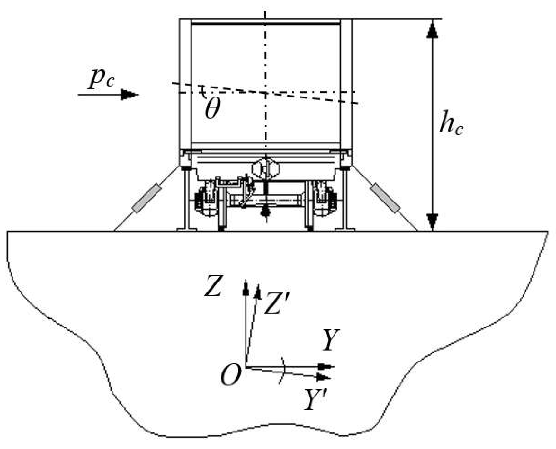
  • Angular displacements around the longitudinal axle X at the angle θ (rolling motion) (Figure 4). At the same time, it was taken into account that the car was symmetrically fixed on the deck with eight ties (four on each side). The ship’s centre of gravity was at the centre of its displacement (YZ coordinate system). The Y′Z′ coordinate system was portable. Under the action of a perturbing influence Pc on the car with a certain height hc, it was displaced at angle θ.
  • The turning motion of the train ferry loaded with cars while approaching the dock.
The dynamic loads on the bearing structure of a car transported via a train ferry were determined with a mathematical model developed by the authors of the article; it characterizes the angular displacement of a train ferry loaded with cars during rolling [10,15].
D 12 g B 2 + 4 z g 2 q ¨ 1 + Λ θ B 2 q ˙ 1 = p h 2 + Λ θ B 2 F ˙ t I θ q ¨ 2 + c b 2 q 2 + β b 2 q ˙ 2 = p k h k 2 + F θ
where q1 and q2 are the generalized coordinates corresponding to the angular displacement of the train ferry and the bearing structure of a car around the longitudinal axle, respectively; D is the ship displacement; B is the breadth of the train ferry; zg is the coordinate of the centre of gravity of the train ferry; Λθ is the coefficient of resistance to the oscillations of the train ferry; p′ is the static motion of the wind relative to the upper projection of the train ferry loaded with cars; h is the hull height; F(t) is the force to the train ferry loaded with rail cars on the decks; β is the coefficient of viscous resistance of a honeycomb panel; c is the stiffness of a honeycomb panel; b is the width of the bearing structure of a car; pc is the wind pressure to the bearing structure of a car; hc is the height of the bearing structure of a car; and Fθ is the moment of the forces acting between the bearing structure and the deck.
The disturbing effect takes the form of a trochoidal law of motion of a sea wave, which has the following form [15]:
F t = a + R e k b sin k a + ω t + b R e k b cos k a + ω t
where a and b are the horizontal and vertical coordinates of the centre of the trajectory along which the particle rotates, which here have the coordinates x and z, respectively; R is the radius of the trajectory along which the particle moves, m; ω is the frequency of the sea wave; and k is the frequency of the trajectory of the disturbing effect.
Significantly, the mathematical model built by the authors of this article can be used to determine the dynamic loads acting on the car transported via various train ferries and water zones where they operate. However, the model includes neither the stagnation of sea waves nor the movement of the freight in the car due to the oscillations of the train ferry. The model also did not include the relationship between the ship’s head and stern. This assumption was based on the fact that the head is about 2.5° of a given wave height. It should also be noted that the modelling of the dynamic load of the open car included the vessel’s nameplate displacement, taking into account its gross tonnage.
These restrictions were based on the experimental research of loading on the bearing structure of an open car transported via sea while rigidly fixed on the deck, as was described in the authors’ previous studies. The research included a full-scale experiment during which the train ferry moved in the Black Sea [16].
Mathematical model (1) was verified with Fisher’s criterion. On the basis of the calculations of the mean squared error Sd = 6.94 and the dispersion of adequacy Sa = 35.42, the actual value of Fisher’s criterion, Fp = 5.11, was obtained, which was less than its tabular value, Ft = 5.41. Thus, the hypothesis on the adequacy of the model was not rejected. The approximation error was about 2%.
The calculation was based on the technical characteristics of the train ferry Geroi Shipki. Mathematical model (1) includes the characteristics of the disturbing force typical of the Black Sea: a sea wave height of 8 m, a length of 120 m, and a wind pressure of 1.47 kPa, according to the reference data on the hydrometeorological characteristics of the sea [17].
A 12-757 open car manufactured by Kryukovsky Railway Car Building Works was taken as the prototype (Figure 5).
The main technical characteristics of the car are shown in Table 1.
The calculation assumed that the honeycomb panel was made of an elastic, viscous material. The viscous resistance coefficient was in the range of 150–165 kN∙s/m, and the stiffness was in the range of 500–520 kN/m. These parameters were determined via mathematical modelling using the sequential selection method.
This mathematical model was solved using MathCad software, version 2015 [17,18,19,20]. The equations were reduced to the form:
F t , y = y 3 y 4 p h 2 + Λ θ B 2 F ˙ t Λ θ B 2 y 3 D 12 g B 2 + 4 z g 2 p k h k 2 + F θ c b 2 y 2 β b 2 y 4 I θ ,
Z = r k f i x e d Y 0 , t n , t k , n , F
where y 1 = q 1 ; y 2 = q 2 ; y 3 = y ˙ 1 ; y 4 = y ˙ 2 .
The function rkfixed is built into the software. This function was used to solve differential equations using the Runge–Kutta method with a constant pitch [21].
The arguments of the function are as follows:
Y0 is the vector of the initial conditions of K elements (k is the number of equations in the system);
tn and tk are the left and right boundaries of the interval where the solution is sought, respectively;
n′ is the number of points within the interval (tn, tk) at which the solution is sought;
F is the vector consisting of K elements, which contains the first derivative of the required functions.
The result of the function is a matrix with p + 1 rows, the first column of which contains the points at which the solution is obtained, and the remaining columns are the solutions.
The generalised accelerations acting on the components of the mechanical system were calculated in the array ddqj,i:
d d q j , 1 = p h 2 + Λ θ B 2 F ˙ t Λ θ B 2 y 3 D 12 g B 2 + 4 z g 2
d d q j , 2 = p k h k 2 + F θ c b 2 y 2 β b 2 y 4 I θ
The initial conditions were taken as equal to zero [22,23,24,25,26].

3. The Results of Calculating the Load on the Open Car Body with Honeycomb Panels

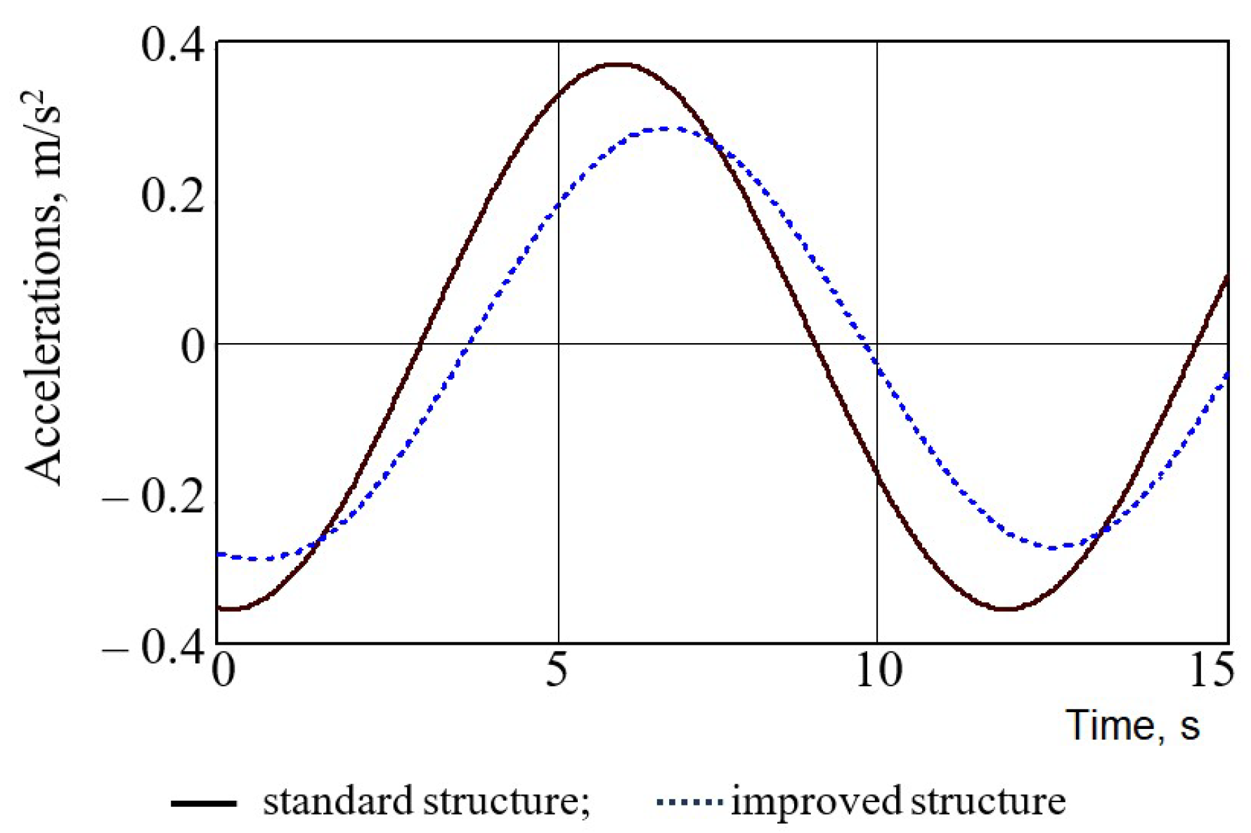
The calculation results show that the application of honeycomb panels could decrease the dynamic load of a car by about 25% more in comparison to that of a standard car (Figure 6). The maximum acceleration for the bearing structure of an open car with the standard frame was 0.38 m/s2, and that for the improved frame was 0.29 m/s2.
Figure 6 presents the accelerations without the horizontal component of free-fall acceleration. Upon including a roll angle of the train ferry of 12.2°, the total acceleration for the bearing structure of an open car with a standard frame was 2.45 m/s2 (0.25 g), and that for the improved frame was 2.36 m/s2 (0.24 g). This roll value was determined for the static wind force to the upper projection of the train ferry with rail cars on its deck.
The following stage of the research included the determination of the load on the bearing structure of a car during the turning motion of the train ferry.
When it was approaching the dock, the ferry turned around for docking to the ramp and rolling off the rail cars.
The following forces were applied to the ferry when it turned around:
  • The forces and moments caused by the ferry engines;
  • The forces on the steering equipment;
  • The forces and inertia moments, including those from the attached water masses;
  • The hydraulic mechanic forces and moments on the ferry body.
Moreover, when the ferry turned around, the following forces acted on it: an inertia force applied to the centre of gravity of the ferry and directed along an instantaneous radius of curvature and an inertia force along a tangential line to the trajectory of the centre of gravity at an instantaneous traffic speed [24].
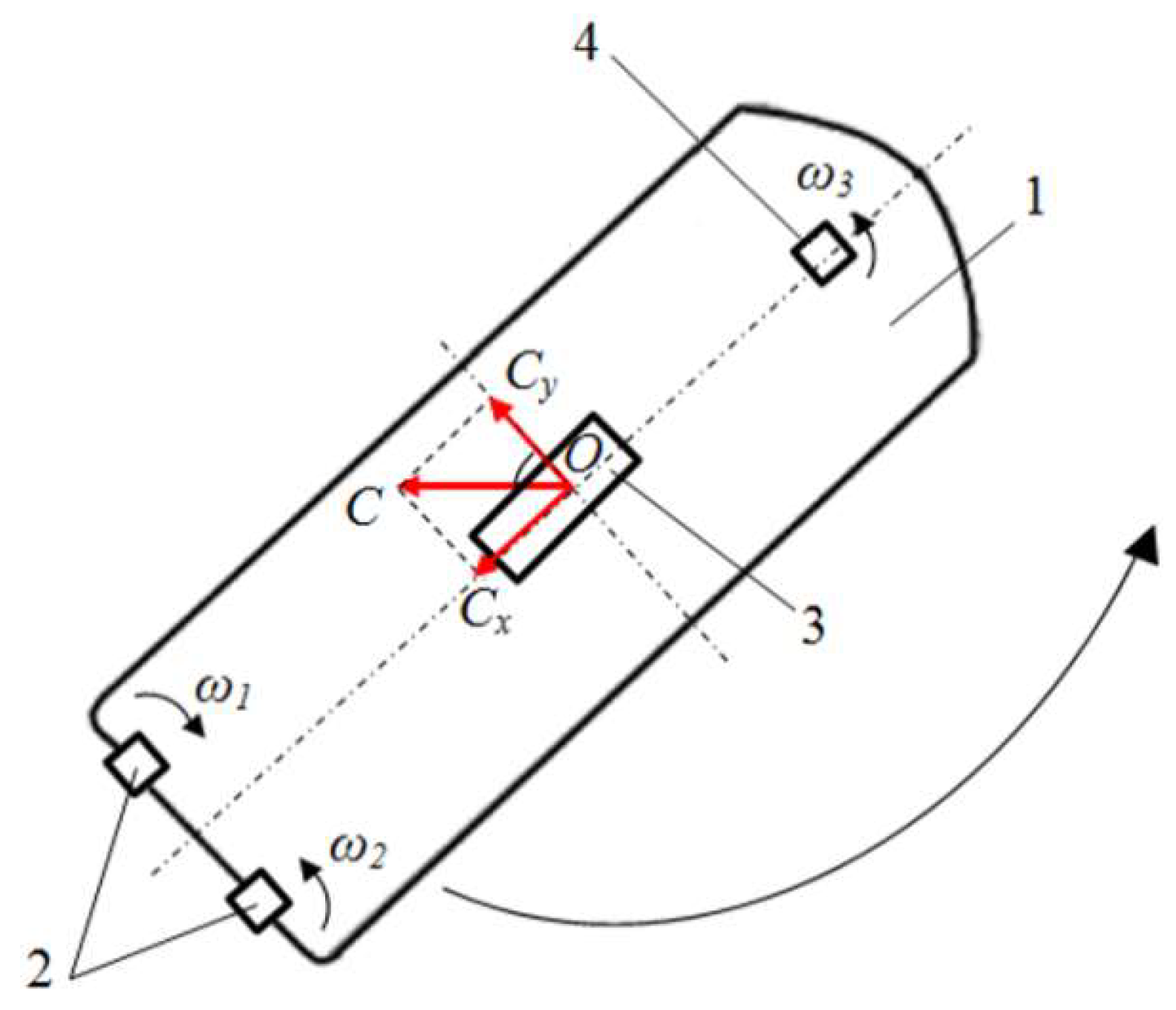
The centrifugal force on the ferry (Figure 7), and thus, on the rail cars located on it, was defined by the following formula [24]:
C = D ϑ 2 R ,
where D is the ship displacement of the train ferry; R is the turning radius; and ϑ is the turning speed.
As is known from theoretical mechanics, the centrifugal force can be found using this formula:
C = D ω 2 ρ ,
where ω is the angular speed and ρ is the turning pole.
When the ferry turned around two stern screws and one front screw began to work, the stern screws acted in opposite directions and formed the moment that facilitated the turning motion of the ferry. The centrifugal force and the forces through the chain binders acted on the rail cars located on the ferry decks.
A diagram of the forces acting on the car body through the chain binders when the ferry turned around is given in Figure 8.
The approximate speed of the turn of the train ferry was ϑ = 1.3 km/h = 0.36 m/s. For the farthest car body from the sternpost, R = 79 m.
Thus, considering that D = 23744 tons, the value of the centrifugal force was C = 39 kN. The force transferred to the car body through the chain binder was F = C/a.
Therefore, the force components in the longitudinal and transverse directions were defined as:
F x = F cos β , F y = F sin β .
The values of the components of the centrifugal force obtained were Fx = 4.9 kN and Fy = 8.4 kN.
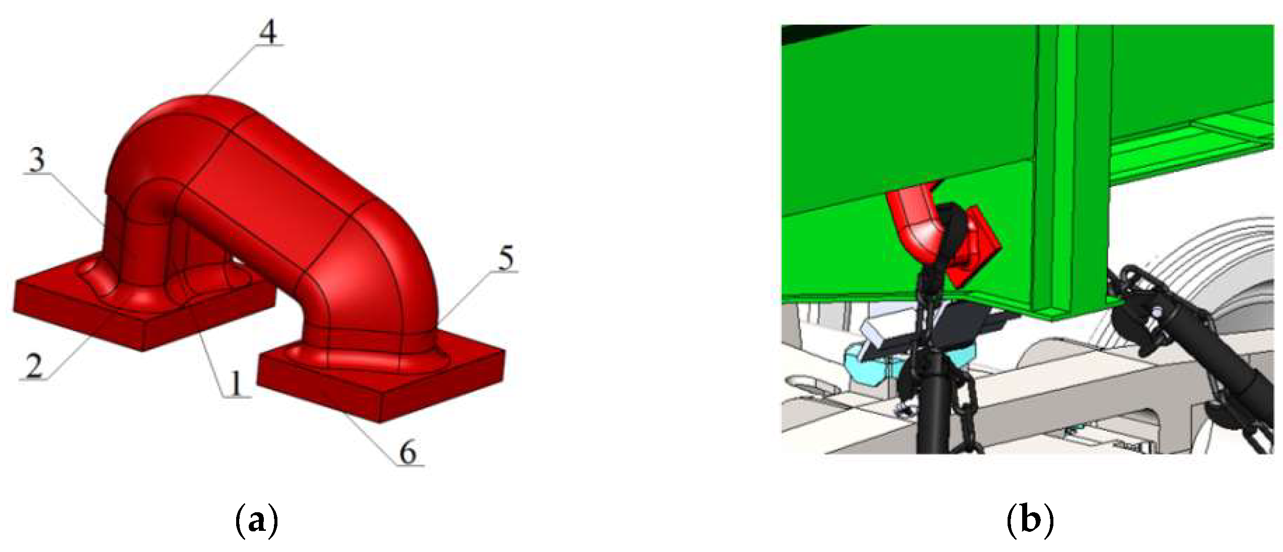
The loads obtained were included in the strength calculation for the bearing structure of an open car with honeycomb panels in the body bolster. It was considered that the car was secured on the deck with the fixing units located on the body bolster (Figure 9) [24].
The unit consisted of the bottom part of the body with hook guide 1 (Figure 9a), which was completely identical to the hitch geometry of the chain binder and intended for interaction with the fixation unit, radial lug 2 for reducing the load in the contact area between the fixation unit and the support part, cylindrical part 3 supporting the contact between the hook and the fixation unit, and the upper part of the body with prismatic part 4 connecting the working and additional parts of the unit with technological reinforcement 5. Support parts 6 were intended for securing the unit on the bolster beam of a rail car (Figure 9b).
In this study, the material of the honeycomb panels and the sizes of their cells were considered conceptually. In the course of the mathematical modelling of the load on the bearing structure of the car, the parameters of the viscosity and stiffness of the panels were determined, which can later be used for selecting a material with appropriate parameters and characteristics. The strength calculation was made with the finite element method in SolidWorks Simulation version 2015 (CosmosWorks) [27,28,29,30].
The authors adhered to the following algorithm while investigating the strength of the body:
  • Building the finite element model of the open car body;
  • Developing its calculation scheme;
  • Developing the body-fixing scheme;
  • Selecting the construction material;
  • Carrying out strength calculations, in which the von Mises criterion was used (the fourth theory of strength). It was taken as the calculation criterion because the material of the body structure was isotropic.
The main hypothesis of this calculation was that a lower dynamic load of the body could improve the strength indicators.
The finite element model included isoparametric tetrahedrons, the optimal number of which was determined using the graphic analytical method [31,32,33]. The number of elements in the mesh was 369,789, and the number of nodes was 120,021. The maximum element size was 100 mm, and the minimum element size was 20 mm. The maximum element side ratio was 1779.8, the percentage of elements with a side ratio of less than three was 21.8%, and the percentage of elements with a side ratio of more than ten was 34.9%. Therefore, the mesh was created on a solid body and included its surface curvatures [34,35,36].
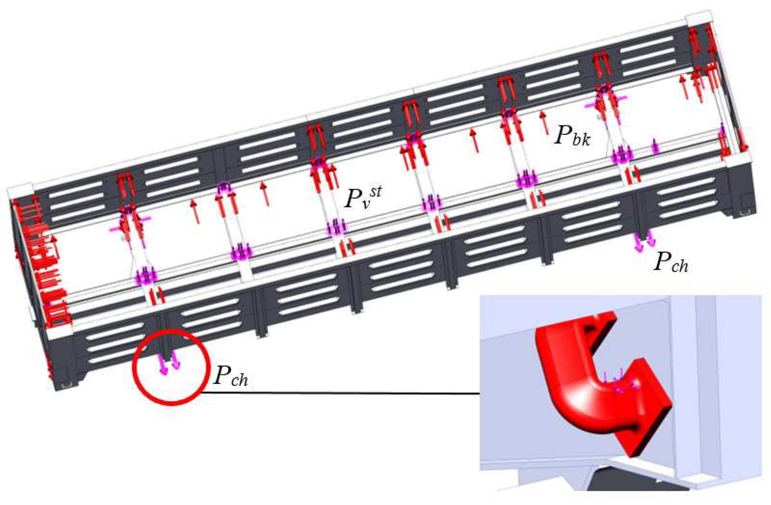
The design diagram of an open car is given in Figure 10. The calculation included the following forces on the bearing structure: the vertical static load Pvst, the pressure forces of the bulk freight Pbk, and the load from the chain binders Pch. As far as the spatial layout of the chain binders is concerned, the load on the bearing structure through them was decomposed in three components. Moreover, the angles of the spatial layout of the chain binders were also included. Mineral carbon was taken as the bulk freight.
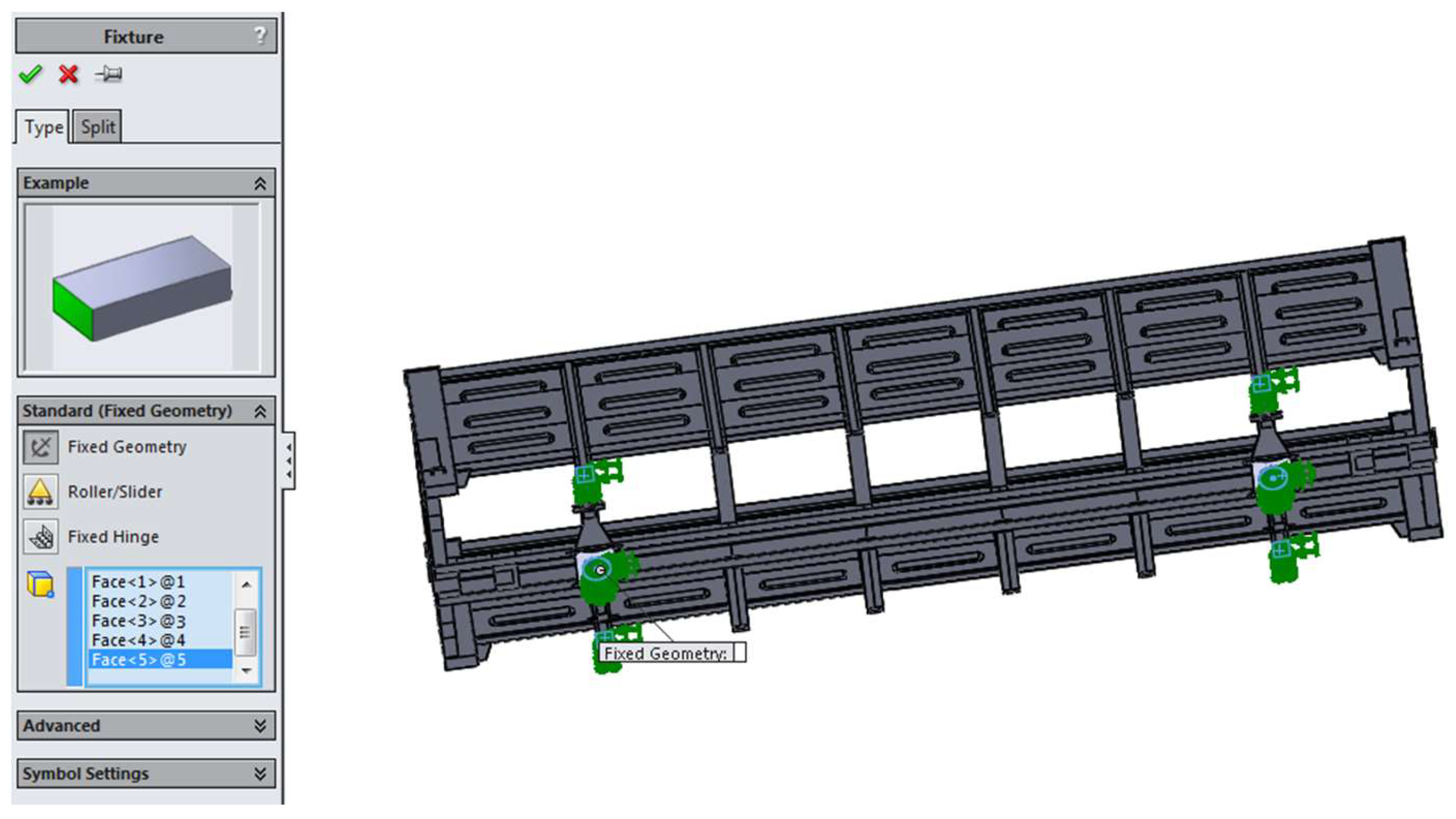
Fixed geometry contacts were used in the areas where the body rested on the bogies, as well as the emphasis jacks (Figure 11).
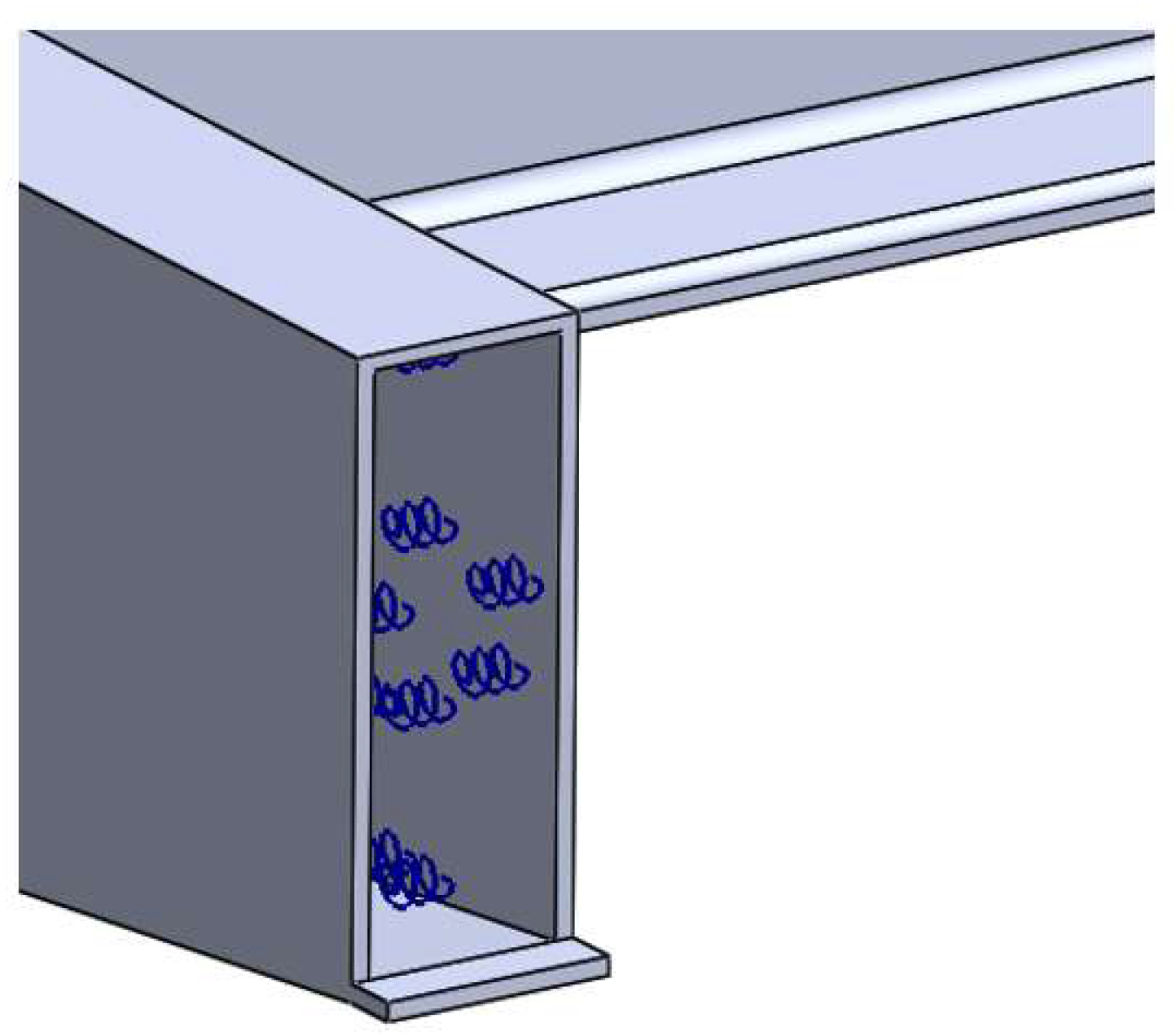
The elastic, viscous material was modelled using the spring–damper links between the vertical parts of the sheets of the body bolster and the intermediate frame beams (Figure 12). Steel (09C2Cu) was used as the material for the supporting structure. Its elastic modulus was 2.1∙105 MPa, its tensile strength was 490 MPa, its yield strength was 345 MPa, and Poisson’s ratio was 0.28.
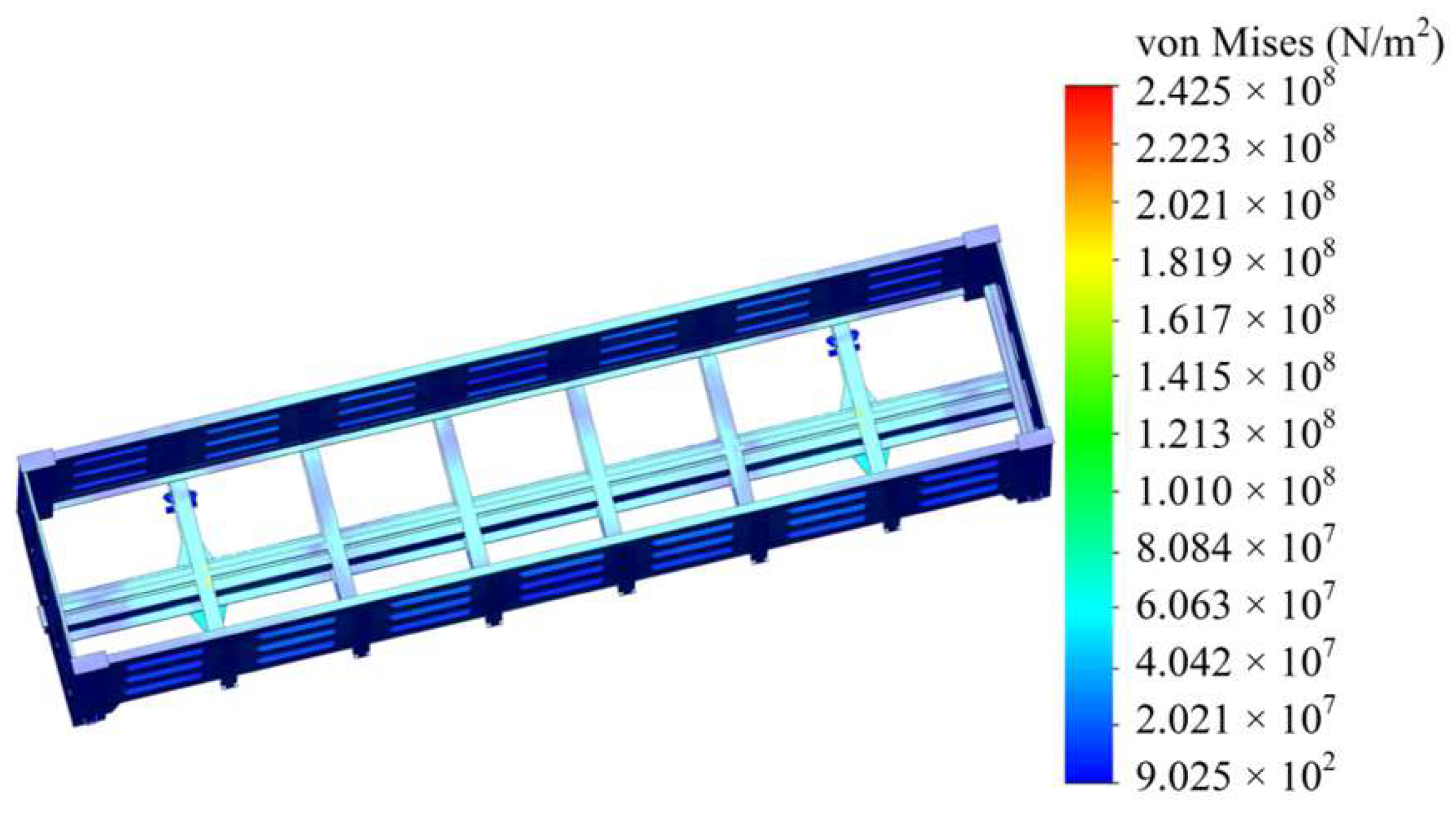
According to the results of the calculation, it was found that the maximum equivalent stresses were in the bolster beam; they were about 240 MPa (Figure 13), which was 30% lower than the loads in the standard bolster beam [37]. In this case, the allowable stresses were determined on the basis of the normative document [37], and they were 310.5 MPa.
The maximum displacements in the bearing structure of an open car were in the middle part of the centre sill; they amounted to about 5 mm (Figure 14). Thus, the strength of the bearing structure did not exceed the allowable values.
The results of the strength calculation for the bearing structure of an open car during the turning motion of the train ferry demonstrated that the maximum equivalent stresses were about 185 MPa, and the displacements were about 5 mm. Thus, the strength of the bearing structure has been provided [37].

4. Discussion

This article presents the determination of the load of an open car with elastic, viscous components in the bearing structure during ro-ro transportation. The improvement was made via the application of elastic, viscous honeycomb panels between the vertical sheets of the intermediate, end, and bolster beams; the intermediate beams of an open car frame were made of a boxed section. This engineering solution can decrease the load of the bearing structure of an open car during interactions with multiple-use lashing devices. The manufacturability of this solution can be explained by the fact that the typical open car design contains reinforcing diaphragms in the bolster beam, with two on each side. The authors proposed the use of honeycomb elements instead of these diaphragms. They can be installed in the bolster beam at the stage of car production. It is possible to use heat-resistant honeycomb elements. Such a solution can ensure the safety of cars during their repair, e.g., during welding.
A mathematical model was used for determining the dynamic load of an open car during the rolling motion of a train ferry. However, the model did not include the impact force of a sea wave on the train ferry. This can be explained by the fact that the centre of gravity of the open car body is 3 m from the bulwark. In accordance with the normative document [38], the impact force of the wave in this case can be neglected.
It was also found that the application of honeycomb panels could decrease the dynamic load of a rail car by about 25% more in comparison to that of a standard structure (Figure 6). It should be noted that, by taking into account the introduction of more advanced energy-absorbing materials in the car structure, the magnitude of the dynamic load can be reduced further.
The loads obtained were included in the strength calculation for the bearing structure of an open car with honeycomb panels in the body bolster. It was found that the maximum equivalent stresses in the bearing structure of an open car did not exceed the allowable values and were 30% lower than the stresses in the standard bolster beam (Figure 13).
The scientific novelty of this study is that the authors built a mathematical model for calculating the dynamic load acting on rail cars transported via sea. It should be noted that this mathematical model was verified through a physical experiment presented in earlier publications by the authors [10,24].
In addition, this study presents a scientific approach for assessing the strength of the bearing structure of an open car, taking into account the improvement for sea transportation.
However, only one type of rail car was studied regarding sea transportation. Therefore, future studies should include other types of rail cars. Moreover, the study conducted did not include the welding seams between the structural components. Thus, future studies will include an evaluation of the strength of these welds [39,40].
The advantage of this study compared to those analysed in the first section of the article is that, in order to ensure the strength of the open car, the authors proposed a reduction in the dynamic loads rather than strengthening the structure. This can be achieved by applying energy-absorbing materials to the frame.
The next stage of this study will include an experimental determination of the strength of an open car body with honeycomb elements using a similar method. This experiment can be carried out under laboratory conditions.
The research conducted can be used by engineers who are concerned about safe and environmentally friendly transportation via train ferries and more efficient ro-ro transportation.

5. Conclusions

  • This study presents an improvement of the bearing structure of an open car in order to provide safe transportation via train ferries. It includes the application of elastic, viscous honeycomb panels between the vertical sheets of the intermediate, end, and body bolster beams; the intermediate beams of the open car frame are made of a boxed section. This solution may reduce the load on the bearing structure of an open car transported via sea. The higher efficiency of a honeycomb panel can be achieved at a viscous resistance coefficient in the range of 150–165 kN s/m and a stiffness in the range of 500–520 kN/m.
  • This study also includes a determination of the bearing structure of an open car during rolling motions. As calculated, the use of honeycomb panels can decrease the dynamic load by about 25% more in comparison to that of a standard structure. The maximum acceleration for the bearing structure of an open car with the standard frame was 0.38, and that for the improved structure was 0.29 m/s2.
  • The authors determined the load of the bearing structure of an open car during the turning motion of a train ferry; it was found that, with a turning speed of the train ferry of v = 0.36 m/s and a turning radius of R = 79, the value of the centrifugal force was C = 39 kN. The components of the centrifugal force acting on the bearing structure of an open car through the chain binders were Fx = 4.9 kN and Fy = 8.4 kN.
  • The strength of the bearing structure of an open car transported via a train ferry was studied. The strength of the bearing structure of an open car transported via sea was calculated.
  • The results of the calculation made it possible to conclude that the maximum equivalent stresses were in the bolster beam; their value was about 240 MPa, which was 30% lower than the loads in the standard bolster beam. The maximum displacements in the bearing structure of an open car were in the middle part of the centre sill; they were about 5 mm.
  • The results of the strength calculation for the bearing structure of an open car during the turning motion of a train ferry demonstrated that the maximum equivalent stress was about 185 MPa, and the displacements were about 5 mm. Thus, the strength of the bearing structure of an open car has been provided.

Author Contributions

Conceptualization, J.G. and A.L.; methodology, A.L.; software, J.D. and O.F.; validation, A.L., J.D. and M.B.; formal analysis, A.L.; investigation, J.G.; resources, O.F.; data curation, A.L. and O.F.; writing—original draft preparation, M.B. and J.D.; writing—review and editing, A.L. and J.G.; visualization, A.L.; supervision, J.D.; project administration, A.L.; funding acquisition, A.L. All authors have read and agreed to the published version of the manuscript.

Funding

This publication was supported by the Cultural and Educational Grant Agency of the Ministry of Education of the Slovak Republic under the project “Implementation of modern methods of computer and experimental analysis of properties of vehicle components in the education of future vehicle designers” (project No. KEGA 036ŽU-4/2021). This research was also supported by the Slovak Research and Development Agency of the Ministry of Education, Science, Research and Sport of the Slovak Republic in the Educational Grant Agency of the Ministry of Education of the Slovak Republic under the project VEGA 1/0513/22 “Investigation of the properties of railway brake components in simulated operating conditions on a flywheel brake stand. This publication is funded through the Recovery and Resilience Plan for Slovakia under the project No. 09I03-03-V01-XXXXX” and project “Scholarships for Excellent Researchers Threatened by the Military Conflict in Ukraine”, which has the code 09I03-03-V01 too.

Institutional Review Board Statement

Not applicable.

Informed Consent Statement

Not applicable.

Data Availability Statement

Not applicable.

Conflicts of Interest

The authors declare no conflict of interest.

References

  1. Soloviova, L.; Strelko, O.; Isaienko, S. Container Transport System as a Means of Saving Resources. In In IOP Conference Series: Earth and Environmental Science, In Proceedings of the International Science and Technology Conference “EarthScience”, Russky Island, Russian Federation, 10–12 December 2020; IOP Science: Bristol, UK, 2020; Volume 459, p. 05200. [Google Scholar] [CrossRef]
  2. Burmaka, I.; Borodulin, A.; Fedorov, D.; Petrychenko, O. External Control of the Divergence Process Taking into Account the Form of the Safety Domain. In Proceedings of the Transport Means-Proceedings of the International Conference, Kaunas, Lithuania, 6–8 October 2021; pp. 579–583. [Google Scholar]
  3. Sotnikov, E.A. World Railways from XX to XXI Century, 1st ed.; Transport: Moscow, Russia, 1993; pp. 1–200. (In Russian) [Google Scholar]
  4. Antipin, D.Y.; Racin, D.Y.; Shorokhov, S.G. Justification of a Rational Design of the Pivot Center of the OpenTop Wagon Frame by means of Computer Simulation. In Procedia Engineering 150, Proceedings of the International Conference on Industrial Engineering, Tehran, Iran, 25–26 January 2016; Elsevier: Amsterdam, The Netherlands, 2016; pp. 150–154. [Google Scholar] [CrossRef]
  5. Milovanovic, V.; Dunic, V.; Rakic, D.; Zivkovic, M. Identification causes of cracking on the underframe of wagon for containers transportation—Fatigue strength assessment of wagon welded joints. Eng. Fail. Anal. 2013, 31, 118–131. [Google Scholar] [CrossRef]
  6. Stoilov, V.; Simic, G.; Purgic, S.; Milkovic, D.; Slavchev, S.; Radulovic, S.; Maznichki, V. Comparative analysis of the results of theoretical and experimental studies of freight wagon Sdggmrss-twin. In IOP Conference Series: Materials Science and Engineering, Proceedings of the International Scientific Conference on Aeronautics, Automotive and Railway Engineering and Technologies BulTrans2019, Sozopol, Bulgaria, 10–12 September 2019; Volume 664, p. 012026. [CrossRef]
  7. Bulychev, M.A.; Antipin, D.Y. Improvement of the method for calculating the strength of the upper straps of the side walls of gondola cars. Bull. Bryansk State Tech. Univ. 2019, 3, 58–64. [Google Scholar] [CrossRef]
  8. Zhang, D.; Tang, Y.; Sun, Z.; Peng, Q. Optimising the location of wagon gravity centre to improve the curving performance. Vehicle Syst. Dyn. 2020, 60, 1627–1641. [Google Scholar] [CrossRef]
  9. Shvets, A.A. Peculiarities of determining the moments of inertia of freight car bodies. Bull. Railw. Transp. Certif. 2018, 5, pp. 20–34. Available online: http://eadnurt.diit.edu.ua/bitstream/123456789/10870/1/Shvets%20.pdf (accessed on 18 May 2023). (In Russian).
  10. Lovska, A.; Fomin, O.; Píštěk, V.; Kučera, P. Dynamic Load and Strength Determination of Carrying Structure of Wagons Transported by Ferries. J. Mar. Sci. Eng. 2020, 8, 902. [Google Scholar] [CrossRef]
  11. Lovska, A. Simulation of loads on the carrying structure of an articulated flat car in combined transportation. Int. J. Eng. Technol. 2018, 7, 140–146. [Google Scholar] [CrossRef]
  12. Hilmola, O.-P.; Li, W.; Panova, Y. Development Status and Future Trends for Eurasian Container Land Bridge Transport. Logistics 2021, 5, 18. [Google Scholar] [CrossRef]
  13. Xing, L.; Xu, Q.; Cai, J.; Jin, Z. Distributed Robust Chance-Constrained Empty Container repositioning Optimization of the China Railway Express. Symmetry 2020, 12, 706. [Google Scholar] [CrossRef]
  14. Karam, A.; Eltawil, A.; Hegner Reinau, K. Energy-Efficient and Integrated Allocation of Berths, Quay Cranes, and Internal Trucks in Container Terminals. Sustainability 2020, 12, 3202. [Google Scholar] [CrossRef]
  15. Lovskaya, A. Assessment of dynamic efforts to bodies of wagons at transportation with railway ferries. East. Eur. J. Enterp. Technol. 2014, 3, 36–41. [Google Scholar] [CrossRef]
  16. Lovska, A.O. Improvement of Load-Bearing Structures of Gondola Cars to Increase the Reliability of Their Fastening on Railway Ferries. Ph.D. Thesis, Ukrainian State University of Railway Nrabsport, Kyiv, Ukraine, 27 June 2013. Available online: https://catalog.odnb.odessa.ua/opac/index.php?url=/notices/index/IdNotice:286648/Source:default (accessed on 20 January 2023). (In Ukrainian).
  17. Lopatukhin, L.I.; Bukhanovsky, A.V.; Ivanov, S.V.; Chernysheva, E.S. Reference Data on the Regime of Wind and Waves of the Baltic, North., Black, Azov and Mediterranean Seas; Russian Maritime Register of Shipping: St. Petersburg, Russia, 2006; Available online: https://files.stroyinf.ru/Data2/1/4293747/4293747775.pdf (accessed on 4 October 2023). (In Russian)
  18. Das, A.; Agarwal, G. Compression, tension & lifting stability on a meter gauge flat Wagon: An experimental approach. Aust. J. Mech. Eng. 2020, 20, 1113–1125. [Google Scholar] [CrossRef]
  19. Leitner, B.; Figuli, L. Fatigue life prediction of mechanical structures under stochastic loading. In Proceedings of the Machine Modelling and Simulations 2017 (MMS 2017), MATEC Web of Conferences, Žilina, Slovakia, 5–8 September 2017; Volume 157, p. 02024. [Google Scholar] [CrossRef]
  20. Panchenko, S.; Vatulia, G.; Lovska, A.; Ravlyuk, V.; Elyazov, I.; Huseynov, I. Influence of structural solutions of an improved brake cylinder of a freight car of railway transport on its load in operation. EUREKA: Phys. Eng. 2022, 6, 45–55. [Google Scholar] [CrossRef]
  21. Bogach, I.V.; Krakovetsky, O.Y.; Kylyk, L.V. Numerical Methods for Solving Differential Equations Using; MathCad: Vinnytsia, Ukraine, 2020; 106p. (In Ukrainian) [Google Scholar]
  22. Dvorak, Z.; Leitner, B.; Novak, L. Software support for railway traffic simulation under restricted conditions of the rail section. Procedia Eng. 2016, 134, 245–255. [Google Scholar] [CrossRef]
  23. Stastniak, P.; Moravcik, M.; Smetanka, L. Investigation of strength conditions of the new wagon prototype type Zans. In Proceedings of the 23rd Polish-Slovak Scientific Conference on Machine Modelling and Simulations (MMS 2018), MATEC Web of Conferences, Rydzyna, Poland, 4–7 September 2019; Volume 254, p. 02037. [Google Scholar] [CrossRef]
  24. Moravec, J. Magnetic field application in area sheet metal forming. In Proceedings of the METAL 2016: 25th Anniversary International Conference on Metallurgy and Materials, Brno, Czech Republic, 25–27 May 2016; pp. 303–309. [Google Scholar]
  25. Goolak, S.; Liubarskyi, B.; Riabov, I.; Chepurna, N.; Pohosov, O. Simulation of a direct torque control system in the presence of winding asymmetry in induction motor. Eng. Res. Express 2023, 5, 025070–025086. [Google Scholar] [CrossRef]
  26. Goolak, S.; Liubarskyi, B.; Riabov, I.; Lukoševičius, V.; Keršys, A.; Kilikevičius, S. Analysis of the Efficiency of Traction Drive Control Systems of Electric Locomotives with Asynchronous Traction Motors. Energies 2023, 16, 3689. [Google Scholar] [CrossRef]
  27. Fomin, O.; Lovska, A. Determination of dynamic loading of bearing structures of freight wagons with actual dimensions. East. Eur. J. Enterp. Technol. 2021, 2, 6–15. [Google Scholar] [CrossRef]
  28. Fanta, O.; Lopot, F.; Kubovy, P.; Jelen, K.; Hylmarova, D.; Svoboda, M. Kinematic analysis and head injury criterion in a pedestrian collision with a tram at the speed of 10 and 20 km.h−1. Manuf. Technol. 2022, 22, pp. 139–145. Available online: https://journalmt.com/pdfs/mft/2022/02/08.pdf (accessed on 2 May 2023).
  29. Vatulia, G.; Komagorova, S.; Pavliuchenkov, M. Optimization of the truss beam. In Verification of the calculation results. In Proceedings of the 7th International Scientific Conference “Reliability and Durability of Railway Transport Engineering Structures and Buildings” (Transbud-2018), MATEC Web Conference, Kharkiv, Ukraine, 14–16 November 2018; Volume 230, p. 02037. [Google Scholar] [CrossRef]
  30. Trakowski, S.; Nieoczym, A.; Caban, J.; Gardynski, L.; Vrabel, J. Reconstruction of road accident using video recording. In Proceedings of the III International Conference of Computational Methods in Engineering Science (CMES’18), MATEC Web of Conferences, Kazimierz Dolny, Poland, 22–24 November 2018; Volume 252, p. 05023. [Google Scholar] [CrossRef]
  31. Svoboda, M.; Chalupa, M.; Cernohlavek, V.; Svasta, A.; Meller, A. Measuring the quality of driving characteristics of a passenger car with passive shock absorbers. Manuf. Technol. 2023, 23, pp. 118–126. Available online: https://mt.ujep.cz/pdfs/mft/2023/01/12.pdf (accessed on 12 April 2023).
  32. Yevtushenko, A.; Topczewska, K.; Zamojski, P. Influence of thermal sensitivity of functionally graded materials on temperature during braking. Materials 2022, 15, 963. [Google Scholar] [CrossRef] [PubMed]
  33. Kondratiev, A.; Gaidachuk, V.; Nabokina, T.; Tsaritsynskyi, A. New Possibilities of Creating the Efficient Dimensionally Stable Composite Honeycomb Structures for Space Applications. In Integrated Computer Technologies in Mechanical Engineering. Advances in Intelligent Systems and Computing; Springer: Cham, Switzerland, 2020; Volume 1113. [Google Scholar] [CrossRef]
  34. Krol, O.; Sokolov, V. Modeling of Spindle Node Dynamics Using the Spectral Analysis Method. In Proceedings of the 3rd International Conference on Design Simulation, Manufacturing: The Innovation Exchange, DSMIE-2020, Kharkiv, Ukraine, , 9–12 June 2020; Volume 1, pp. 35–44. [Google Scholar] [CrossRef]
  35. Krasoń, W.; Niezgoda, T.; Stankiewicz, M. Innovative Project of Prototype Railway Wagon and Intermodal Transport System. Transp. Res. Procedia 2016, 14, 615–624. [Google Scholar] [CrossRef]
  36. Kapitsa, M.; Mikhailov, E.; Kliuiev, S.; Semenov, S.; Kovtanets, M. Study of rail vehicles movement characteristics improvement in curves using fuzzy logic mechatronic systems. In Proceedings of the 2nd International Scientific and Practical Conference “Energy-Optimal Technologies, Logistic and Safety on Transport” (EOT-2019), MATEC Web of Conferences, Lviv, Ukraine, 19–20 September 2019; Volume 294, p. 03019. [Google Scholar] [CrossRef]
  37. DSTU 7598: 2014; Freight cars. General Requirements for Calculations and Design of New and Modernized Cars of 1520 mm track (Non-Self-Propelled). UkrNDNTS: Kyiv, Ukraine, 2015; 162p. (In Ukrainian)
  38. Marine Engineering Bureau. Manual on Securing Cargo for the Ship “Petrovsk”; Marine Engineering Bureau: Odessa, Ukraine, 2005. (In Russian) [Google Scholar]
  39. Šutka, J.; Koňar, R.; Moravec, J.; Petričko, L. Arc welding renovation of permanent steel molds. Arch. Foundry Eng. 2021, 21, 34–40. [Google Scholar]
  40. Moravec, J.; Gryc, K. Forming and heat treatment of modern metallic materials. Metals 2021, 11, 1106. [Google Scholar] [CrossRef]
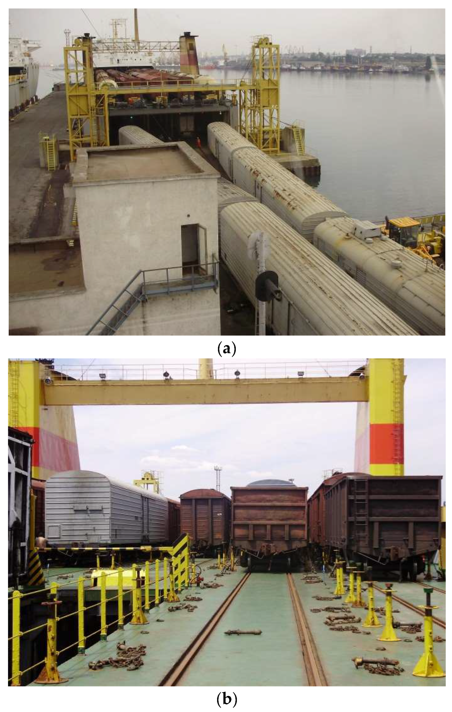
Figure 1. Ro-ro transportation of cars: (a) cars loading onto a deck; (b) cars arranged on a deck.
Applsci 13 11022 g001
Figure 2. Section of the cross bearer of an open car frame: (a) standard structure; (b) improved structure.
Applsci 13 11022 g002
Figure 3. Improved frame of an open car.
Applsci 13 11022 g003
Figure 4. Diagram of movements of the open car body during oscillations of the train ferry.
Applsci 13 11022 g004
Figure 5. Open car model 12-757.
Applsci 13 11022 g005
Figure 6. Accelerations of the bearing structure of an open car.
Applsci 13 11022 g006
Figure 7. Diagram of the centrifugal force on the ferry with a car on board when the ferry turns. 1—train ferry; 2—stern engines; 3—rail car; 4—stern engine.
Applsci 13 11022 g007
Figure 8. Diagram of the forces acting on a car body through the chain binders when the ferry turns. 1—rail track; 2—car; 3—ferry deck; 4—chain binder; Fx and Fy—projections of the forces acting on the car body through the chain binder.
Applsci 13 11022 g008
Figure 9. Fixation unit of the bearing structure of a car on the deck: (a) structural components of the unit; (b) an open car body fixed on the deck.
Applsci 13 11022 g009
Figure 10. A design diagram of the bearing structure of an open car.
Applsci 13 11022 g010
Figure 11. Modelling of the contacts of the body with bogies and jacks.
Applsci 13 11022 g011
Figure 12. Modelling of an elastic, viscous link between the vertical parts of the sheets in the frame’s intermediate beams.
Applsci 13 11022 g012
Figure 13. Stress state of the bearing structure.
Applsci 13 11022 g013
Figure 14. Displacements in the units of the bearing structure.
Applsci 13 11022 g014
Table 1. The main technical characteristics of the car.
ParameterUnitValue
Carrying capacity t69.0
Tare weight t25.0
Design speedkm/h120
Dimensions1–VM (0–T)
Base mm8670
Length along the coupler axlesmm13,920
Number of axles4
Two-axle bogie18-100
Inside body lengthmm11,228
Inside body widthmm2964
Inside body heightmm2315
Disclaimer/Publisher’s Note: The statements, opinions and data contained in all publications are solely those of the individual author(s) and contributor(s) and not of MDPI and/or the editor(s). MDPI and/or the editor(s) disclaim responsibility for any injury to people or property resulting from any ideas, methods, instructions or products referred to in the content.