Abstract
In order to study the mechanism of crack propagation in rock cutting, experiments and discrete element numerical simulation of rock cutting at different depths were adopted in this paper. The rock fragmentation can be divided into mini-size fragmentation and normal-size fragmentation from a size viewpoint. The discrete element method (DEM) is used to further investigate the mechanism of normal size fragmentation at different depths and record the process of crack initiation and propagation. Additionally, the paper characterizes the process of crack initiation and examines the representative rock fragmentation. According to the mechanism of crack development, rock fragmentation can be divided into three categories: conventional failure, fracture failure, and damage failure. The fragmentation of three kinds of failure has one common point. To form semi-dislodged rock fragmentation, the macroscopic shear cracks are first formed. Subsequently, the tensile failure at weak places causes fragmentation ejection. Therefore, the mechanism of fragmentation generation in rock cutting is investigated in terms of crack initiation and extension. In this study, the fracture phenomenon of previous rock cutting experiments is reproduced by an experiment, and the failure process is analyzed in detail by the discrete element method, which reveals the essence of producing fragment phenomena and summarizes the fracture phenomenon and damage crack propagation mechanism in rock cutting.
1. Introduction
Rock cutting is one of the primary methods of mechanical rock fragmentation. The efficiency of rock cutting may be increased via research, which can also shorten construction cycles and lower construction costs. Early research on rock-cutting mainly focused on the rock-cutting properties of big drill rigs, which examined the rock-breaking efficiency under various depths and tooth configurations [1]. Numerous academics have expanded on the subsequent study, and various theoretical conclusions have been reached.
Substantial experiments and observational data demonstrated that the basic damage of rocks is in the form of ductile collapse and brittle fracture [2,3,4]. Brittle fracture is the result of crack development, whereas plastic collapse is the outcome of plastic deformation and flow, which seldom results in additional micro-cracks. For rock cutting, when the depth of it is shallow, the damage belongs to the ductile collapse. However, as the depth of the cut increases, the damage converts to the brittle one. Huerta and Malkin [5] investigated that when the cutting depth is less than 1μm, tiny fragments occur and are not accompanied by micro-cracks. It is called ductile failure, which occurs in the surface failure experiments of rock materials. It is commonly accepted that the size of the rock fragmentation in brittle fracture generated by rock cutting is closely proportional to the depth of rock cutting, which was proven in the investigation by Lin and Zhou [6,7]. Namely, Bazant’s Size Effect Law for quasi-brittle material was proved to be applicable to rock cutting. There was little research on the form of crack propagation and the fine mechanism of chip flaking in the related research of rock cutting, which was mainly focused on the essence of ductile collapse and brittle fracture and the mechanism of the ductile–brittle transition.
In many experimental studies of rock cutting, the cutting depth is usually used as an experimental variable to study the rock breaking mechanism and rock breaking effect at different depths. Detournay’s [8] team conducted a variety of deep downcutting experiments and proved that the formation mechanism of small debris also exists between plastic failure and brittle failure. Microcracks that form as a result of drilling teeth pushing outward cause small fragmentations. These small fragmentations appear as thin flakes, and the lithology and cutting depth have an impact on the chip size. Detournay et al. [9] analyzed three stages of cutting process from weight on bit, torque on bit, depth of cutting and speed, and proposed mathematical models of parameters such as weight on bit and torque on bit in different stages. There is intermittently generated little fragmentation in addition to the discontinuous development of huge fragmentation in the brittle damage. The study conducted by Dai et al. [10] proposed a novel approach to determine the transformation of rock failure mode based on the analysis of cutting forces at various cutting depths. The effectiveness of this method is validated through a series of single PDC cutter tests. Many other scholars have also carried out cutting experiments at various depths, such as Refs. [11,12,13,14,15].
The study of damage cracks and debris formation has an important impact on the subsequent fracture generation and even determines the basic form of fracture generation in the damaged area. PDC teeth linear cutting trials were seen using high-speed cameras and post-experimental sections by Cheng Z et al. [16]. It was discovered that the primary fracture in rock cutting creates curved rock fragmentation that is either directed toward the rock matrix or the free surface.
In certain numerical calculations and tests, such as those by Zeuch et al. [17] and He et al. [18], damage fragmentation beneath cutting pits have been examined. Potential fragmentation can only be analyzed in sections after the trials since they are challenging to see in rock-cutting experiments. Hence, there is pertinent research on the way damage fragmentation form during cratering and how they affect future cutting. When the cutting depth is more than the critical depth for ductile damage during rock cutting, rock fragmentation begins to form. Macroscopic fissures that extend to the free surface from the tip of the drill tooth are what cause the fragmentation to develop. This procedure yields fragmentation that breaks off in the center as well as fragmentation that is completely intact. Figure 1 illustrates this behavior, which has been shown in several experimental experiments [13,14,16], which can be found in both brittle damage and the small fragmentation phase that is proposed by Zhang [13].

Figure 1.
Fracture Phenomenon of Rock Fragmentation by PDC Teeth. Note: (a) Zhen [16]; (b) Zhang [13]; (c) Liu [14], The red Arrow in figure shows the location of the rock fragmentation fracture.
Previous rock cutting experiments can only observe the surface of the phenomenon, which is difficult to analyze from a microscopic point of view. Numerical simulation techniques must be used in order to more thoroughly explore the mechanism of fracture development and expansion. Liu, H. [19] utilized numerical methods to investigate the impact of mechanical tools on rock cutting processes and identified that the fragmentation of rocks is primarily attributed to side cracks. Huang and Detournay [2] conducted numerical indentation and cutting experiments using discrete element method to verify the influence of the two ratios on the failure mode. Liu and Zhu [14] established an experimental device and the discrete element model to further study the force response and fragmentation formation of PDC tools at different DOCs, cutting speeds, and forward inclination angles. It is thought that the fragmentation created during the rock cutting can be divided into three parts. He and Xu [18] simulated rock cutting with standard particle creation and rock cutting with particle cluster technique formation by utilizing the PFC2D discrete element software. The damage crack is effectively replicated by both techniques, yielding favorable results in the experimental investigation of crack propagation mechanism in rock cutting. Moreover, the simulation outcomes exhibit superior performance during the small fragment stage and the brittle damage stage. Liu et al. [20] utilized the discrete element method (PFC2D) to numerically simulate the rock cutting process and replicate the transition of rock failure. The investigation encompasses the progression of rock failure and its influencing factors while validating the accuracy of the critical depth of cut model through numerical simulation results and laboratory experiments. Yang et al. [21] examined the rock-breaking mechanism of cross-cutting PDC bits by combining experimental data with numerical simulations. By establishing a nonlinear dynamical model, this study analyzes stress distribution within rock units, sliding fracture characteristics, plastic energy consumption, and stress distribution along the cutter edge during cross-cutting processes. Mohammadnejad, M. [22] proposed finite-discrete element method (FDEM) combining the finite element method (FEM) and the bonded particle model (BPM) to simulate the process of rock cutting and breaking rock. The crack development in the simulation of rock cutting at different depths is identified as a mixed type I-II crack. Some scholars that used finite element method to simulate rock cutting [23,24,25] also had good results.
To sum up, in the experiment and simulation of the rock cutting, the development of the rock crack is processional. Main cracks and damaged cracks are both a part of the crack growth process. The damaged cracks can be in the direction of cutting, extending into the rock matrix or sprouting from the middle of the main cracks. Among them, damaged cracks have a significant impact on the following fragmentation and can even determine the basic shape of the damaged region. Early research on rock cutting rarely contained the process analysis on the development of rock cracks, seldom considering the influence of disturbance factors, such as damage cracks that accompany the cutting process and natural factors such as rock porosity and rock joints on cracking. Through the use of thin-slice rock cutting experiments, discrete element numerical methods, and some previous experimental and theoretical findings, the single-tooth linear cutting of sandstone is simulated in this paper, and the failure process is analyzed in detail by the discrete element method, which reveals the essence of fracture phenomenon. Additionally, the mechanism of the generation of rock chips that are accompanied by damage cracks was examined.
2. Experiment and Simulation
2.1. Rock Cutting Experiment
The experimental sandstone rock samples were first subjected to UCS (Uniaxial Compressive Strength), MOE (Modulus of Elasticity) and BTS (Brazilian Tensile Strength) studies, and the parameters such as strength and modulus are obtained. The fundamental strength parameters were determined as given in Table 1.

Table 1.
Basic Mechanical Properties of Rocks and Models.
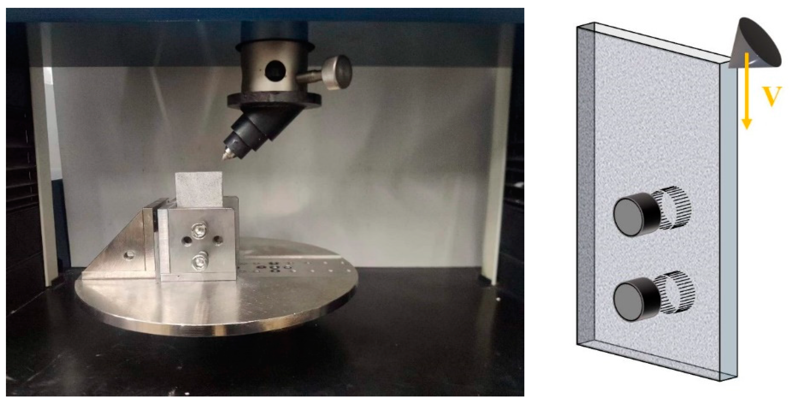
The uniaxial pulling and pressing tester, as seen in Figure 2 below, served as the basis for the design of the rock-cutting tool. The beam of the tester supplied the loading route and speed for the cutting experiment. A fixture held the thin rock sample to the chassis, and the cutting tool was a shovel-shaped tooth with a 60° angle. The uniaxial pulling and pushing tester placed restrictions on the data collection technique, allowing for the collection of just the cutting force in one direction.
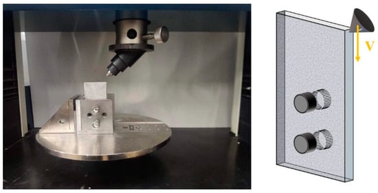
Figure 2.
Rock Cutting Experimental Device.
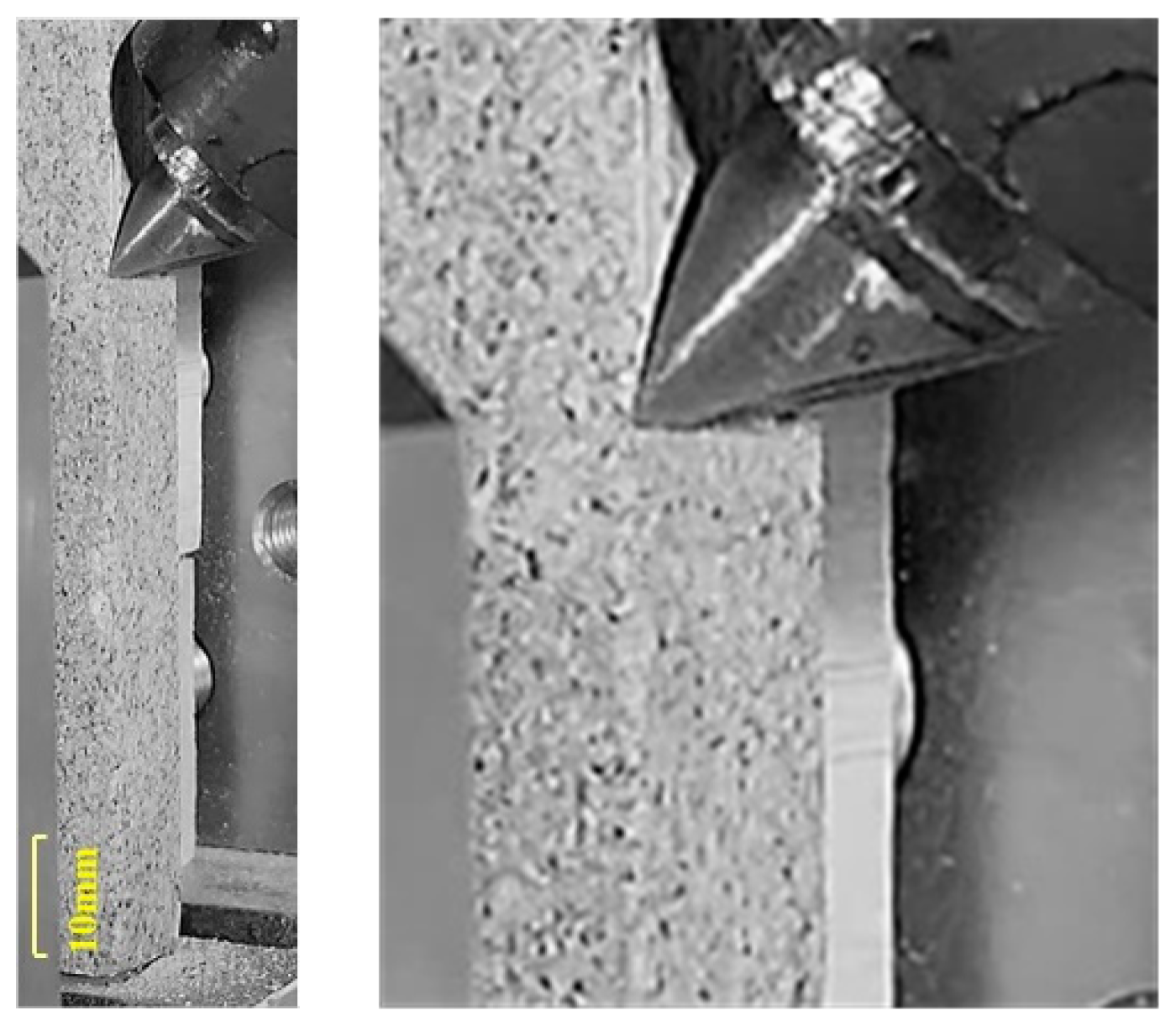
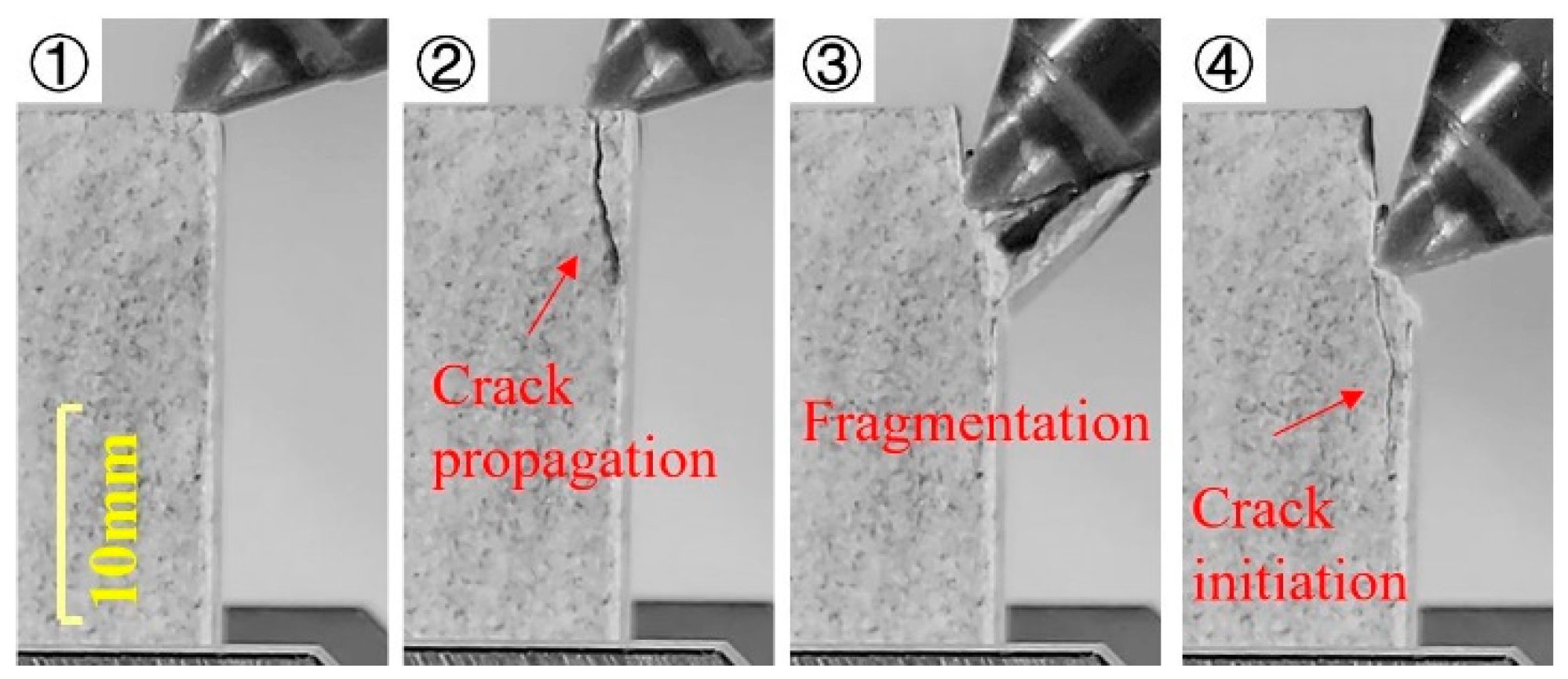
In order to study the special phenomenon of fragment breaking apart in the middle, the following experiment was designed with reference to the ductile-small fragmentation-brittle phase mentioned in Zhang’s research [13]. This study focuses on the initiation and propagation of cracks, so it does not conduct in-depth research on plastic failure in rock cutting. For the experiments, four cutting depths, 0.5 mm, 1.5 mm, 2.5 mm, and 3.5 mm, and three experiments under each depth, were used, and the crushing circumstances are depicted in Figure 3, Figure 4, Figure 5 and Figure 6. As can be seen in the figures, no macroscopic fissures and no big rock fragmentations were created when the cutting depth was 0.5 mm. Instead, the crushed rock fragmentation just exited the crushing zone via gravity. When the cutting depth reached 3.5 mm, the rock sample was invaded at the drill teeth’s point of contact, causing the rock to sprout cracks. These cracks then spread along the drill teeth’s velocity direction to form macro cracks, which eventually turned into semi-dislodged rock fragmentation before falling off.
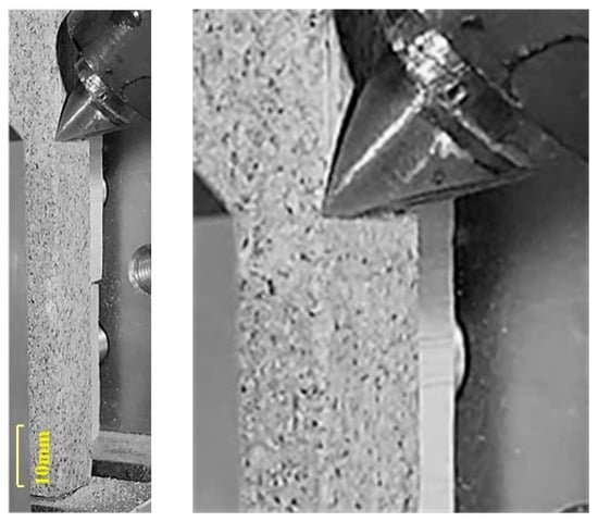
Figure 3.
Rock-Cutting Experiment (DOC = 0.5 mm).

Figure 4.
Rock-Cutting Experiment (DOC = 1.5 mm). Note: The numbers ①–⑥ refer to the chronological order of the cutting tests; the following figure is the same.

Figure 5.
Rock-Cutting Experiment (DOC = 2.5 mm).
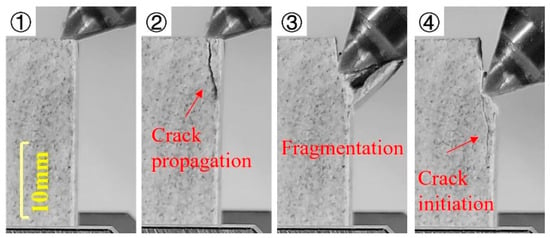
Figure 6.
Rock-Cutting Experiment (DOC = 3.5 mm).
Figure 3 shows clear ductile damage, a powdered crushing region, and a collection of powdered debris the tool created after breaking the rock. The rock fragmentation formed in Figure 4 was continuous and unbroken, and they were produced intermittently but unbrokenly in response to the entry of the tool. The fragmentation was merged into a skin of variable thickness, which was accompanied by ductile damage over time. In Figure 5, the rock fragmentation was also shattered from the center, a phenomenon known as the fracture phenomenon, in addition to the discontinuous formation and ductile damage. This stage of the damage may have been categorically categorized as brittle damage in Figure 6 because a bigger fragmentation and a macroscopic shear crack that appear to have been caused by tool intrusion are created.
The PFC discrete element method was used for the numerical simulation of rock-cutting experiments in order to more thoroughly investigate the aforementioned experimental phenomena in rock-cutting experiments, the crack development process of ductile-small fragmentation-brittle damage, and the generation mechanism of fracture-shaped rock fragmentation.
2.2. PFC Model
Particle Flow Code (PFC) is a method of dynamic numerical analysis that can be utilized to simulate in-homogeneous, discontinuous, and large deformation properties in rock experiments [26]. This approach considered the motion of the block after the force was applied with the consequent condition of force and block motion, then estimated the motion of the particle in accordance with Newton’s Second Law of Motion and many constitutive relations. This paper adopted PFC2D to investigate the initiation and expansion of the cracks as well as the generation of crack fragmentation.
In PFC2D, if the particle itself is a disc-shaped rigid body, the motion of the particles follows Newton’s Second Law of Motion to conduct force and energy through contact. If the contact form between particle is overlapping, it is supposed to be calculated by the magnitude of the overlap and adheres Hooke’s Law.
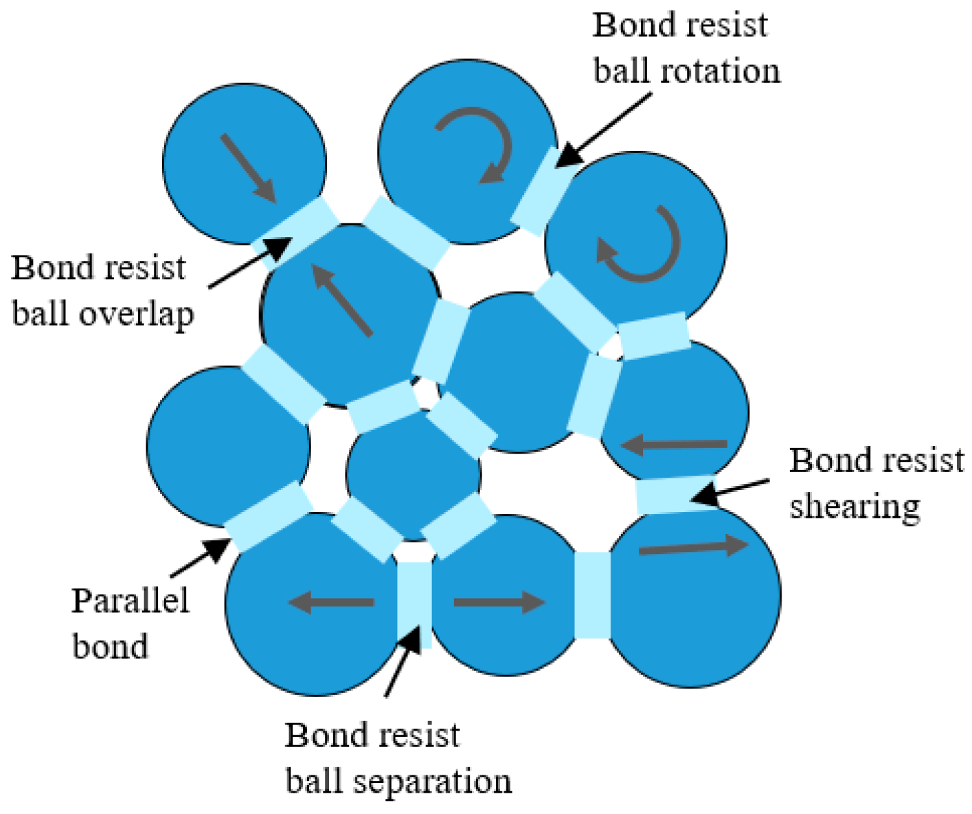
PFC simulation material on bulk particles, including the CB-model, PB-model, and different joint models, must be put up for particle bonding. In this paper, the process of fracture propagation of sandstone rock cutting is analyzed, and the model of parallel bonding is selected after careful deliberation. The functions of parallel bonding are shown in Figure 7. The rectangular bonding shape is situated on the particle’s contact plane, at the center of the contact point, and it offers rotational resistance as well as normal and shear bond stiffness. The bond contact is parallel to the linear contact of the particle body.
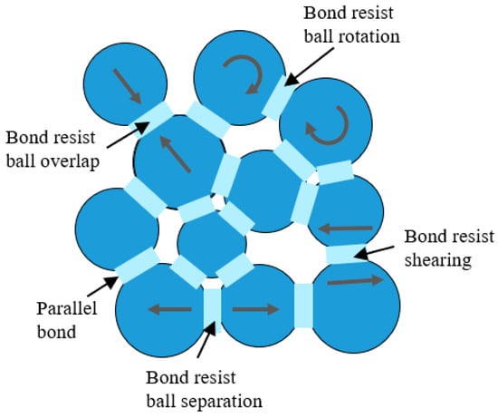
Figure 7.
Schematic Diagram of Parallel Bonding. Note: The arrows within the sphere depict the trajectory of its motion, the following figure is the same.
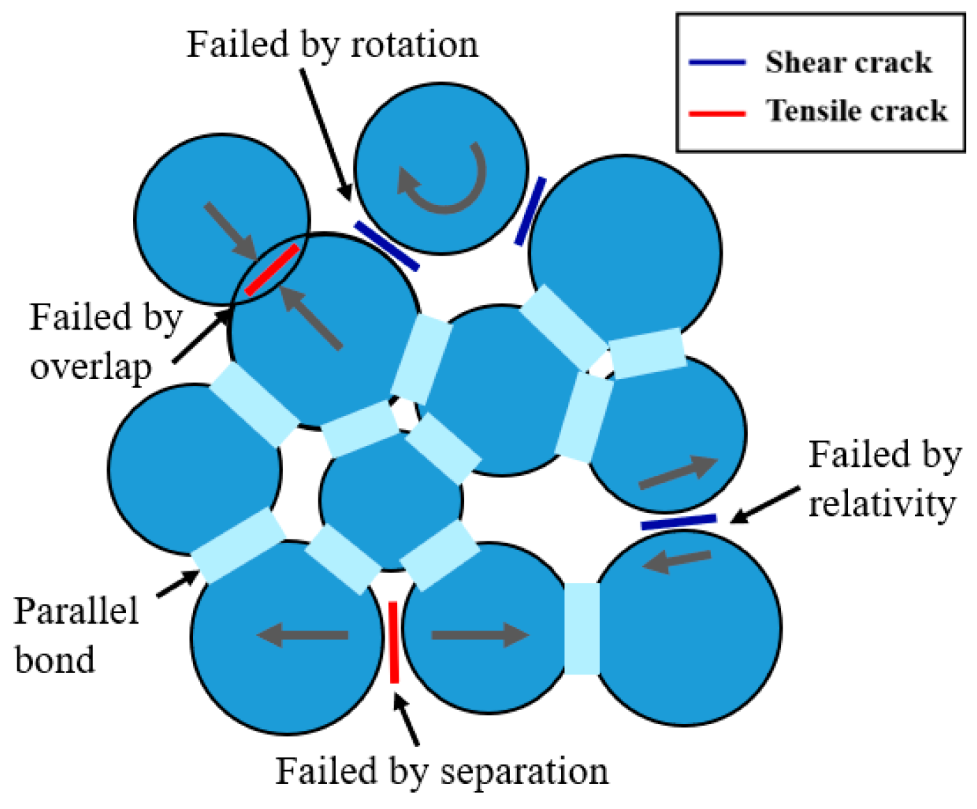
If relative movement occurs at the contact after bonding is established, the elastic interaction can impart force and torque. The force and torque act on the contacts of two bonds and are associated with the maximum normal and shear stresses acting around the bond and within the bonded material. The particle model exhibits linear elastic tensile, compressive, and rotational behavior. If the stress of the bond exceeds the limit of its corresponding strength, the bond fracture will occur. The bonding material corresponding to the fractured bond and its accompanying forces, torques, and strengths are removed from the model, and the fracture degenerates into the linear contact models, resulting in tensile and shear cracks in the model [27,28]. The Discrete Fracture Network was used to separate the tensile crack from the shear fracture in order to better understand the mechanism of crack initiation and expansion in rock cutting. The principle is shown in Figure 8. There are four reasons for bond fracture, which are rotation, interleaving, separation, and overlap. Among them, the bond fracture caused by rotation and interleaving will produce a shear crack in situ, and the bond fracture caused by separation and overlap is a tension crack.
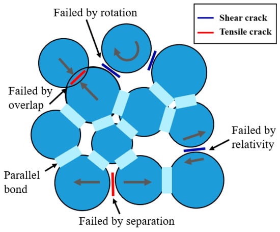
Figure 8.
Damage Behavior of Parallel Bond [28].
To better determine the parameters of the sandstone model and characterize the crack initiation process and the formation mechanism of rock fragmentation, the indoor experiments of rock sample was first conducted in this paper. The sandstone basic mechanical parameters shown in Table 1 were obtained from the UCS and BTS experiment. According to the measured mechanical parameters of the sandstone, the particle parameters and bond parameters of PFC rock model as shown in Table 2 are selected after calibration.

Table 2.
Particle parameters influence tests.
Where emod (E) is the effective modulus; k-ratio is the normal-to-shear stiffness ratio; pb-k-ratio is bond normal-to-shear stiffness ratio; friction is the friction coefficient; pb-emod () is the bond effective modulus; pb-fa is friction angle, pb-coh is cohesion, pb-ten is tensile strength.
In PFC2D (Particle Flow Code 2D) simulation, many simulation experiments need to be conducted before determining appropriate particle micromechanical parameters. The specific calibration process is based on the research results of previous scholars [13,29].
The particle parameters influence analysis shown in Table 2 were designed, and the influence law of each parameter is obtained (limited to briefly show only).
Multi-parameter comprehensive calibration was carried out against the results of indoor experiments within the recommended range, and the final parameter selection is shown in Table 3. After the calibration of the parameter, the corresponding particle parameters and mechanical properties of the model foundation are obtained as follows:

Table 3.
Parameter of Rock Model Particles.
Where density is particle density; pb-gap is the interval between particle.
After the calibration of parameters, we can obtain a set of particle model attributes that can better simulate the sample. As shown in Table 4, UCS, MOE, BTS and IPSS (In-Plane Shear Strength) obtained from the compression, tensile, and shear simulation are the basic mechanical properties of the set of particle parameters, which can be adopted in the subsequent rock-cutting simulation.

Table 4.
Basic Mechanical Properties of Models.
2.3. Numerical Simulation of Rock Cutting
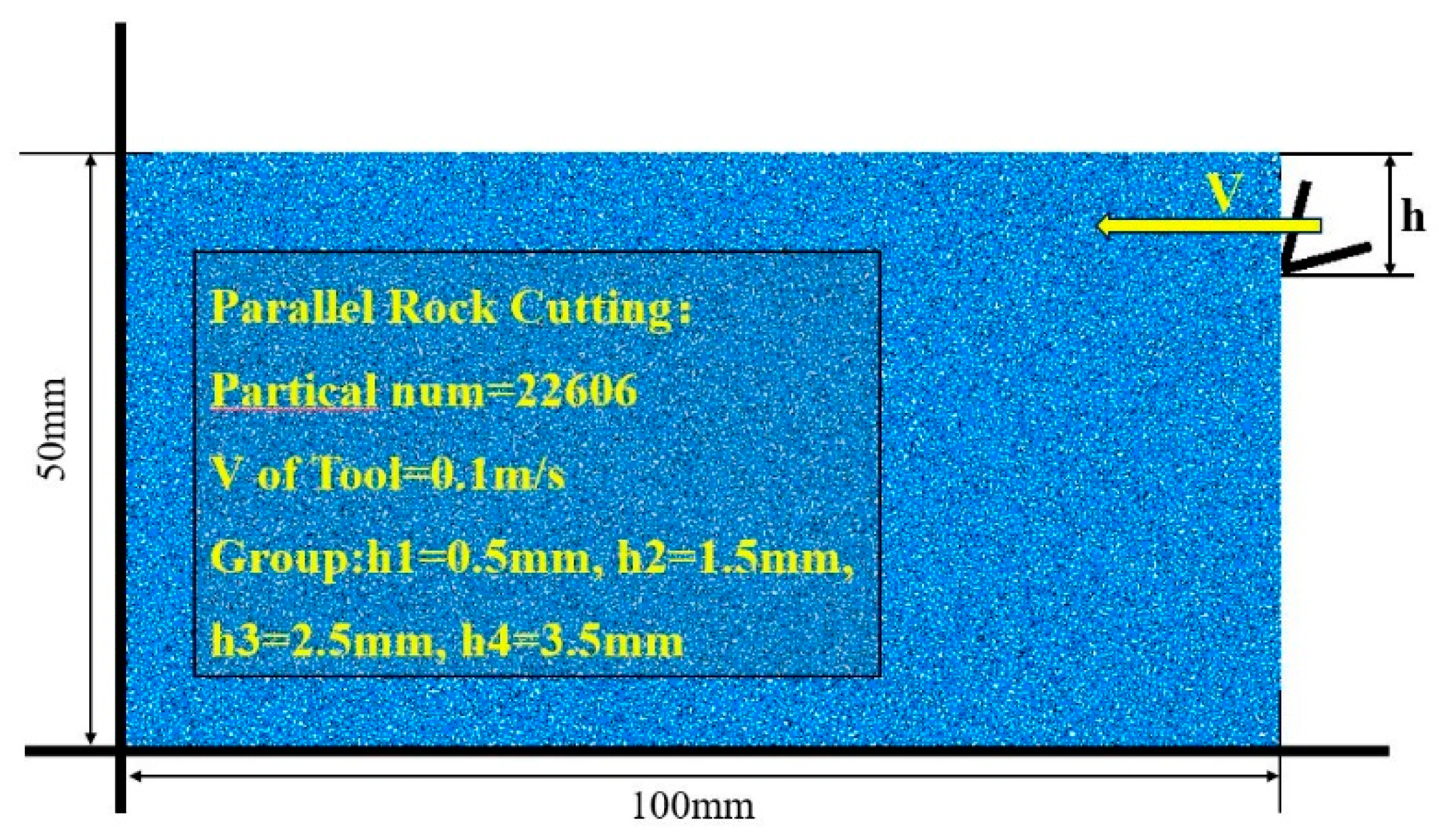
The aforementioned particle characteristics are used in this study to carry out a numerical simulation of rock cutting. A 2D sample of a 50 × 100 mm centered particle is made from a rock sample, with a total of 22,606 particles. As shown in Figure 9, the simulation of rock cutting uses parallel cutting and continuous loading (parallel cutting is continuous cutting at a fixed cutting depth).
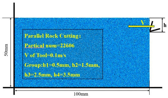
Figure 9.
A Sketch of Numerical Simulation of Rock Cutting.
In this research, parallel cutting tests were conducted in four groups of continuous cutting experiments, with each group’s depth being varied. The designed experimental model and the loading mode are shown in Figure 6. The variable for the parallel cutting experiment was the depth of cut (DOC), with four experimental groups of h1 (1D, D is the mean diameter of the particles, D = 0.5 mm), h2 (3D), h3 (5D), and h4 (7D). Multiple PCFs were recorded, respectively, for each experiment and the total number of cracks, debris particles, and NFs, and the corresponding cutting lengths for each set were also recorded. The process of generating parts of the rock fragmentation was replayed.
The experimental results were recorded in Table 5.

Table 5.
The Experiment Results of Rock Cutting Simulation.
3. Results and Discussion
3.1. The Statistic of Cracks and Particles
The failure of rock materials includes two types: ductile failure and brittle failure [6,7,9,30]. This paper focuses on the brittle failure in the process of rock cutting.
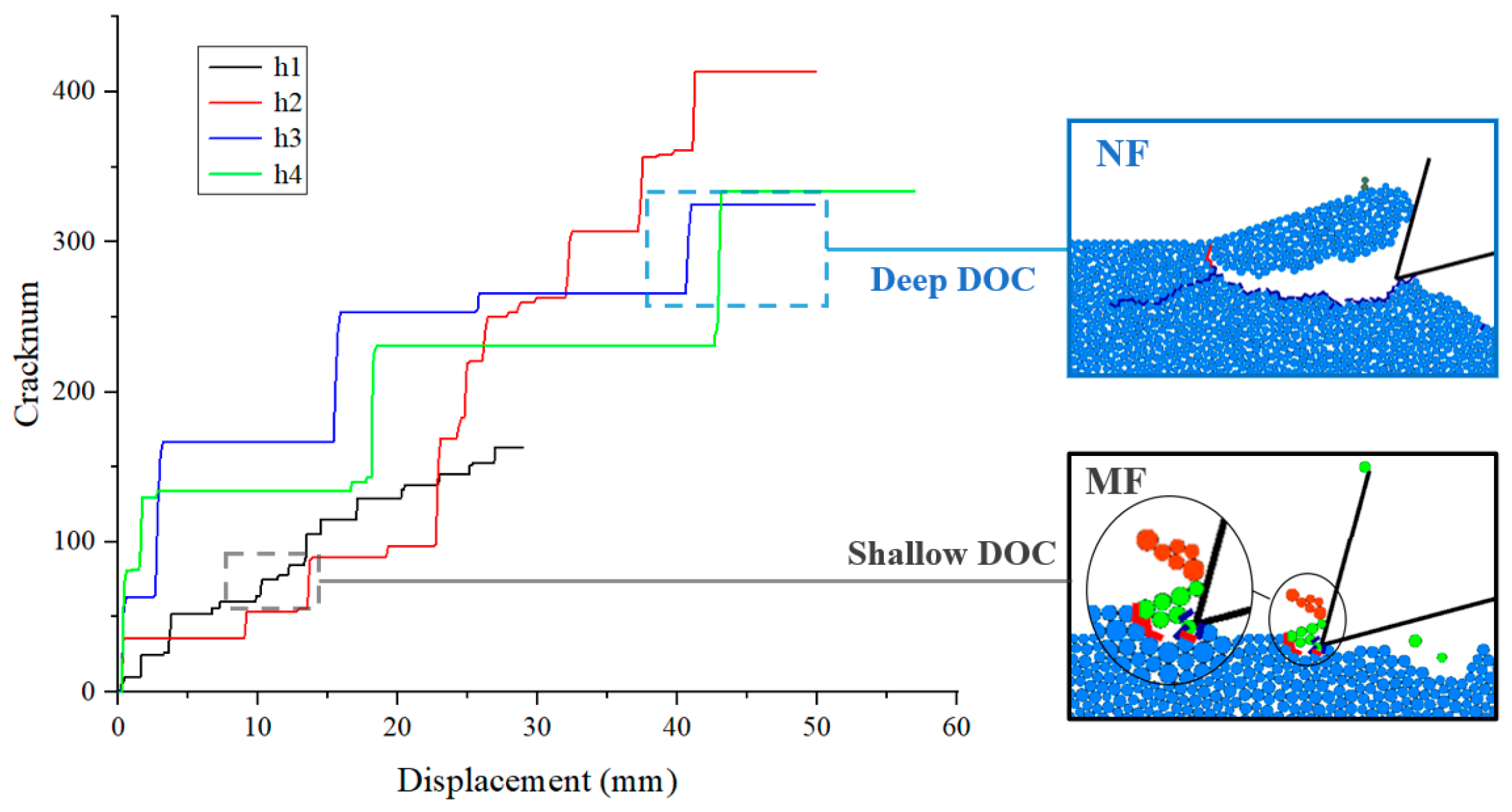
A comparison of crack number with cutting process and cuttings number with cutting depth was conducted for four experimental groups, with cutting depth as a variable in order to examine the differences in cutting volume and cutting formation processes at different depths. In the cutting process of the h1 experimental group, the number of particles in the cuttings is mostly less than 10, which corresponds to the small crack step and belongs to small-size fragmentation, conforming to the fragmentation stage in the ductile-fragmentation–brittle failure mode. However, the particles of fragments h2, h3, and h4 are much larger than h1, and the normal size cuttings produced in h2, h3, and h4 correspond to the large crack step in the crack diagram, the crack steps at various depths are illustrated in Figure 10. Additionally, in the process of producing large fragmentation, it will be accompanied by partial fragmentation and produce small cracks.
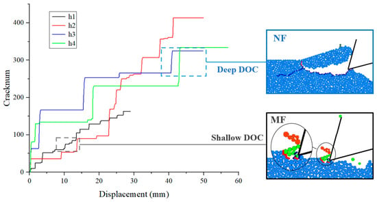
Figure 10.
Datagrams of Continuous Parallel Cutting Crack.
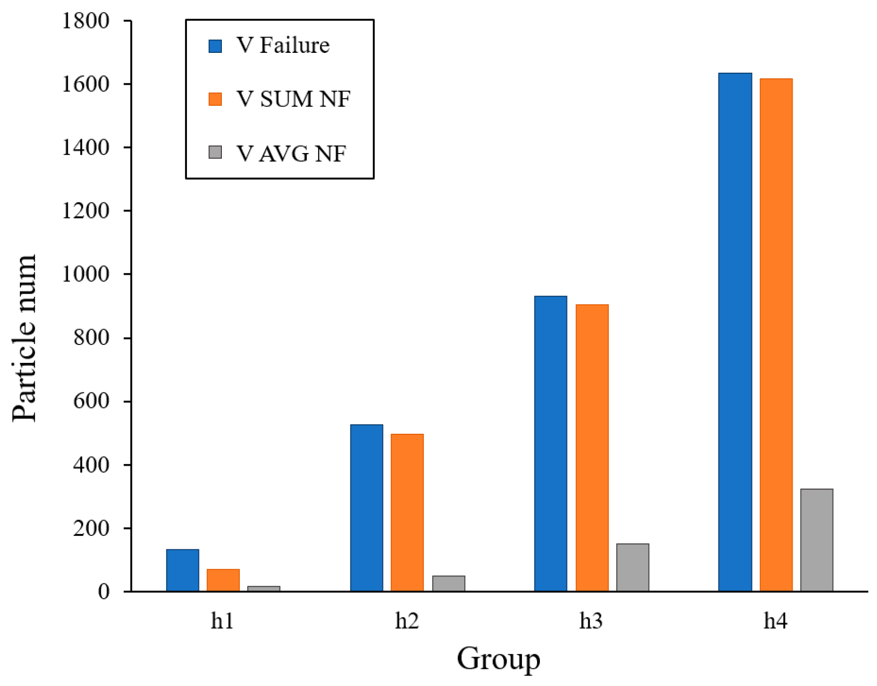
This research aims to define the cutting volume by the fragments’ particle number, but it is restricted to 2D in order to evaluate the link between the sizes of cuts made under various cutting depths in PFC2D. The volume of fragmentation is characterized by a granular area with unit thickness. MF is a mini-size fragment, and NF is a normal-size fragment. The volume of normal-size fragment cuts and the overall volume of cutting failure from four sets of experiments are statistically analyzed as follows:
As shown in Figure 11, the relationship of rock fragmentation particles between group of shallow DOC h1 and group of deep DOC h2, h3, and h4 is calculated. It can be observed that MF is dominant in shallow DOC, whereas NF is dominant in deep DOC, which complies with the results of previous rock-cutting experiments and simulations [31]. It is worth mentioning that there are more MFs in the h2 group, and the staggered pattern of large and small steps is also shown in Figure 7.
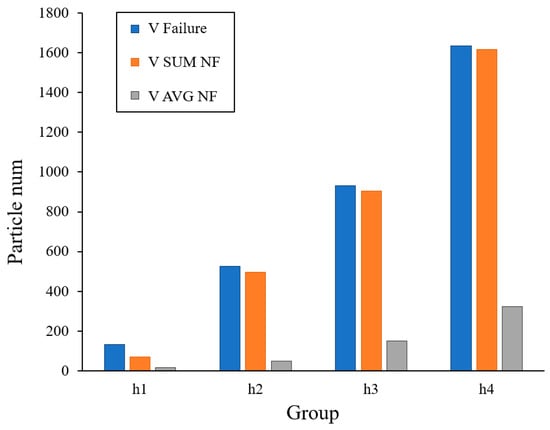
Figure 11.
The Relationship Between the Number of Failure Particles and the Number of Normal-size Particles in Parallel Cutting.
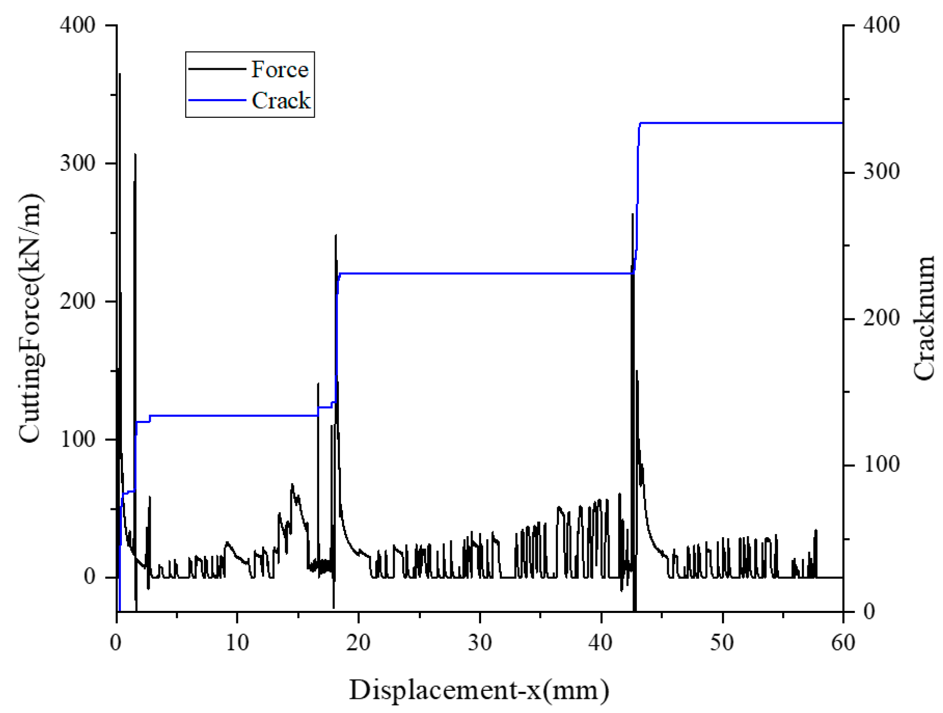
Figure 12 illustrates a straightforward examination of the cutting force and fractures using a simulation with 3.5 mm DOC. It can be investigated that the existing time for the Peak Cutting Force (PCF) in the numerical simulation is quite short. The cutting force reaches the peak value at the moment before the crack number increases sharply, which is consistent with the release of a large amount of strain energy after the crack propagation, as described in the previous research, resulting in a steep drop in the contact force of the rock-breaking tool. The development of fragmentation during rock cutting is demonstrated to be a periodic progressive failure [32].
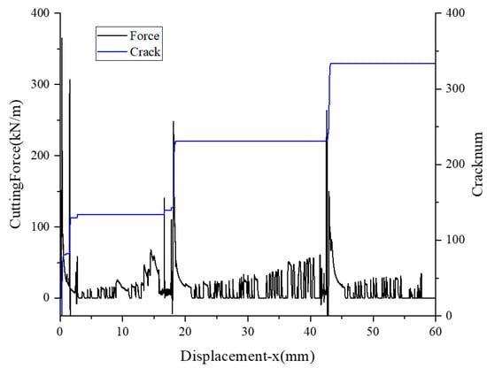
Figure 12.
DOC = 3.5 mm Relationship Between Cutting Force and Number of Cracks.
3.2. Cutting-Force Analysis
The multi-cutting PCF at various depths is derived from a numerical simulation of rock cutting. The single PCF is easily affected by the damaged crack, and the damaged area of the previous cutting is more unstable. It can be understood that the strain energy of the next rock cutting corresponding to the crack is released in advance, so the PCF of the same set of experiments is chosen for the analysis. The following three PCF models are chosen for investigation referring to the previous methods of studying peak cutting force [33,34,35,36].
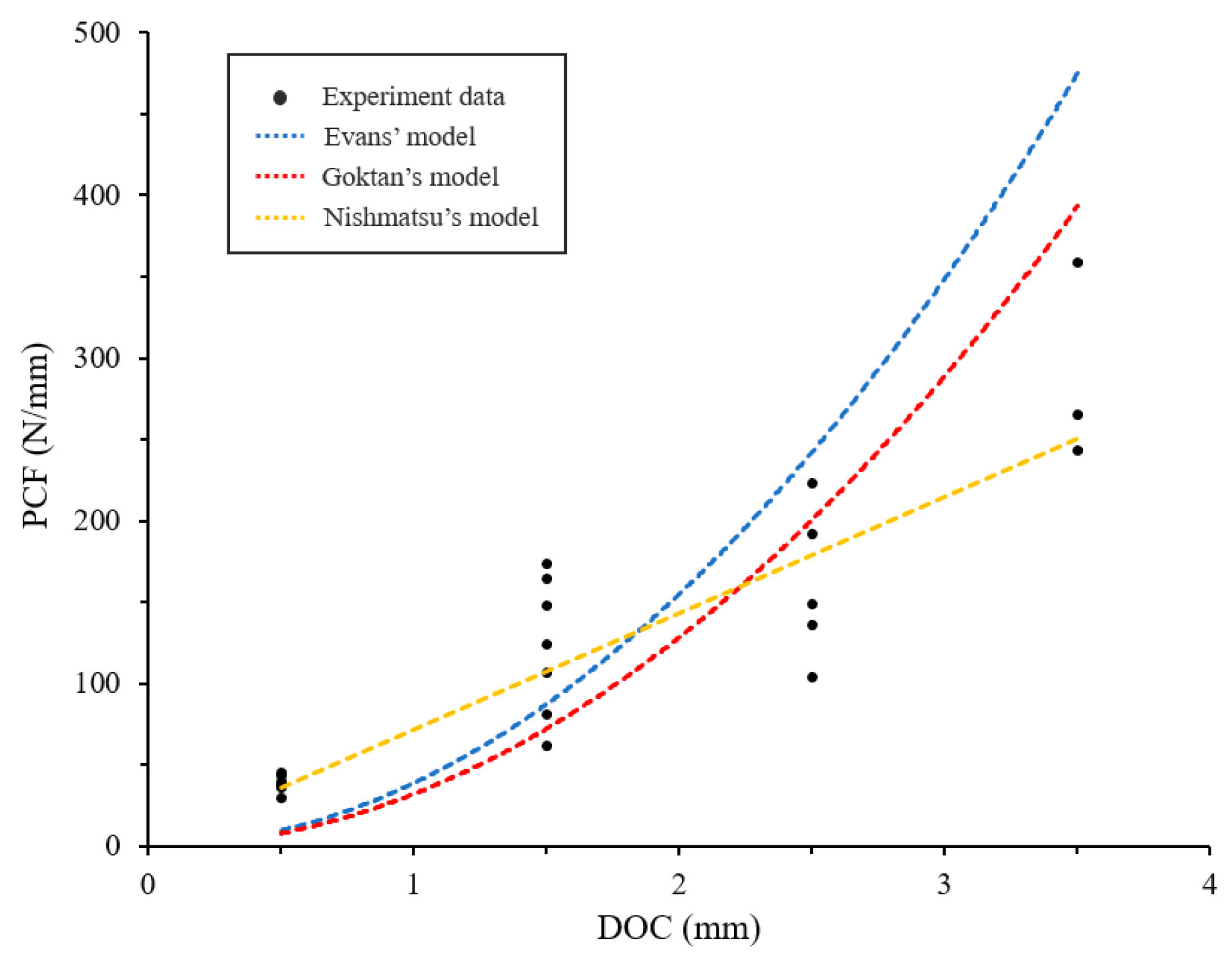
Evans [37,38] proposed a theoretical model based on the maximum tensile strength criterion for the prediction of the cutting force of conical teeth, and it is considered that the formation of rock fragmentation is caused by tensile failure, which is shown in Equation (1).
where is the peak cutting force of Evans’ model. is the depth of cut. is the tool width. is the semi-tip angle of cutting tool. and are uni-axial compressive strength (UCS) and the Brazilian tensile strength (BTS) values of the rock.
Goktan [39,40] modified Evans’ model and took the friction between the rock and the tool into consideration, which was shown in Equation (2).
where is the peak cutting force of Goktan’s model. is the friction angle between the rock and tool. The other notations are the same as those used in Equation (1).
Nishmatsu [32] believed that the rock failure was caused by shear cracks produced by drilling teeth, and a rock cutting model was proposed based on the theory of Mohr–Coulomb. Nishmatsu pointed out that his theory applied to coarse cutting chips produced by the propagation of brittle fracture cracks, which was shown in Equation (3).
where is the peak cutting force of Nishmatsu’s model. is the shear strength of specimen rock. is the angle of internal friction. is the rake angle of the cutting tool. The other notations are the same as those used above.
As shown in Table 6, the parameters required in Equations (1)–(3) are calculated and converted from the previous section.

Table 6.
Rock Model Parameters and their Corresponding Values.
Figure 13 displays the experimental peak forces in a scattered form together with three distinct cutting force models. The numerical simulation is a 2D model, thus the unit of measurement is N/mm (kN/m), which is better correlated with Nishmatsu’s model than the experimental data. In Nishmatsu’s theory, the first macro-crack is a shear crack, and the shear failure happens after the macro-crack, resulting in a sharp reduction in force. In order to verify whether the force drop is caused by the shear failure of the macro shear crack, the conventional size cuttings at different depths of cut are analyzed. The research is described below.
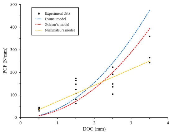
Figure 13.
Comparison of Experimental Peak Force and Model Peak Force.
3.3. Continuous Cutting Analysis
In the description of rock cutting by leap-forward, there is a common point in the cracking stage. The cuttings are formed by the initiation of cracks in the crushing zone, which is formed by the contact between the tool and the fracture surface after the last cuttings fell off. Based on this theory, the simulation results of rock continuous cutting are analyzed in this paper.
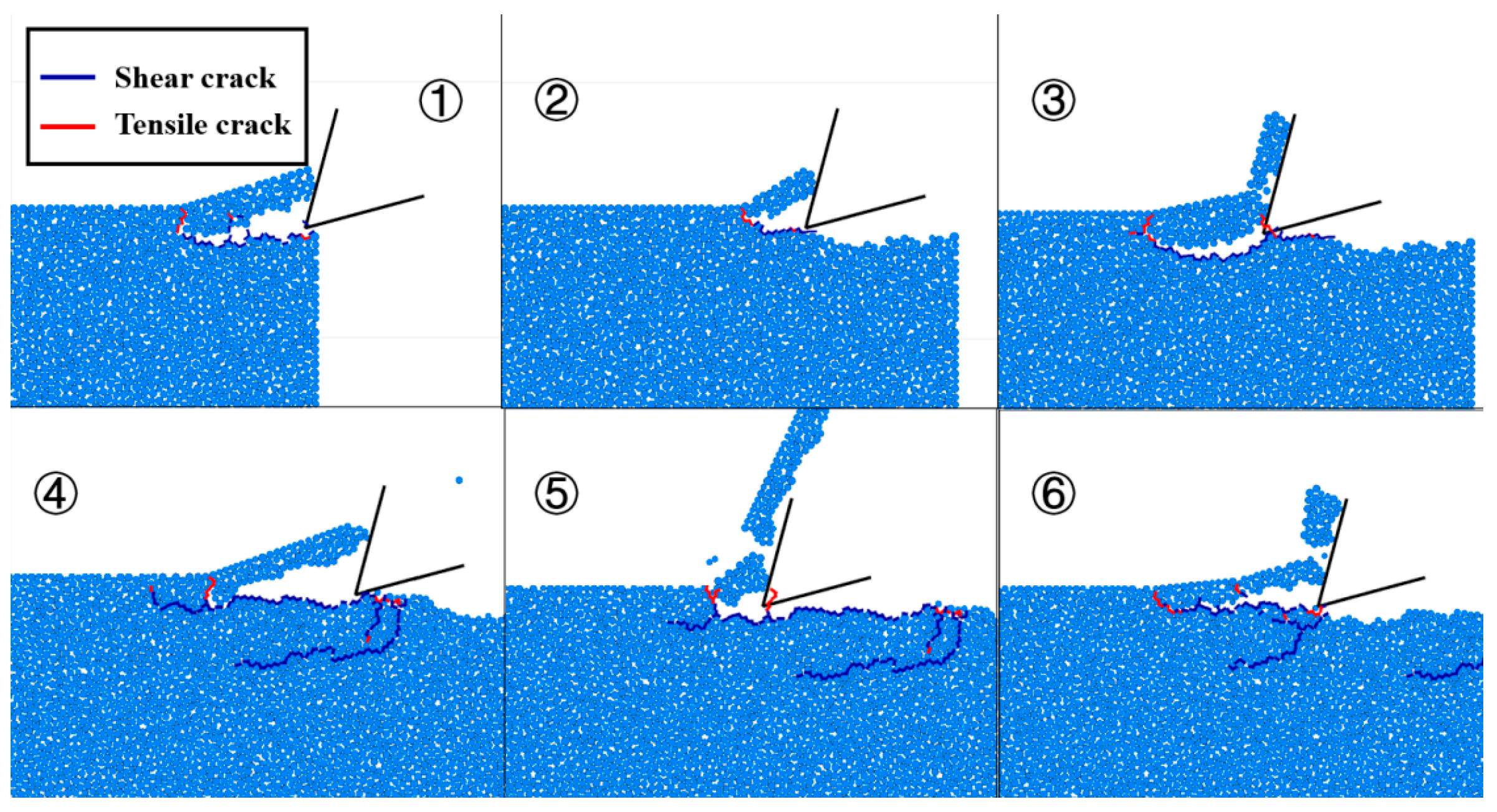
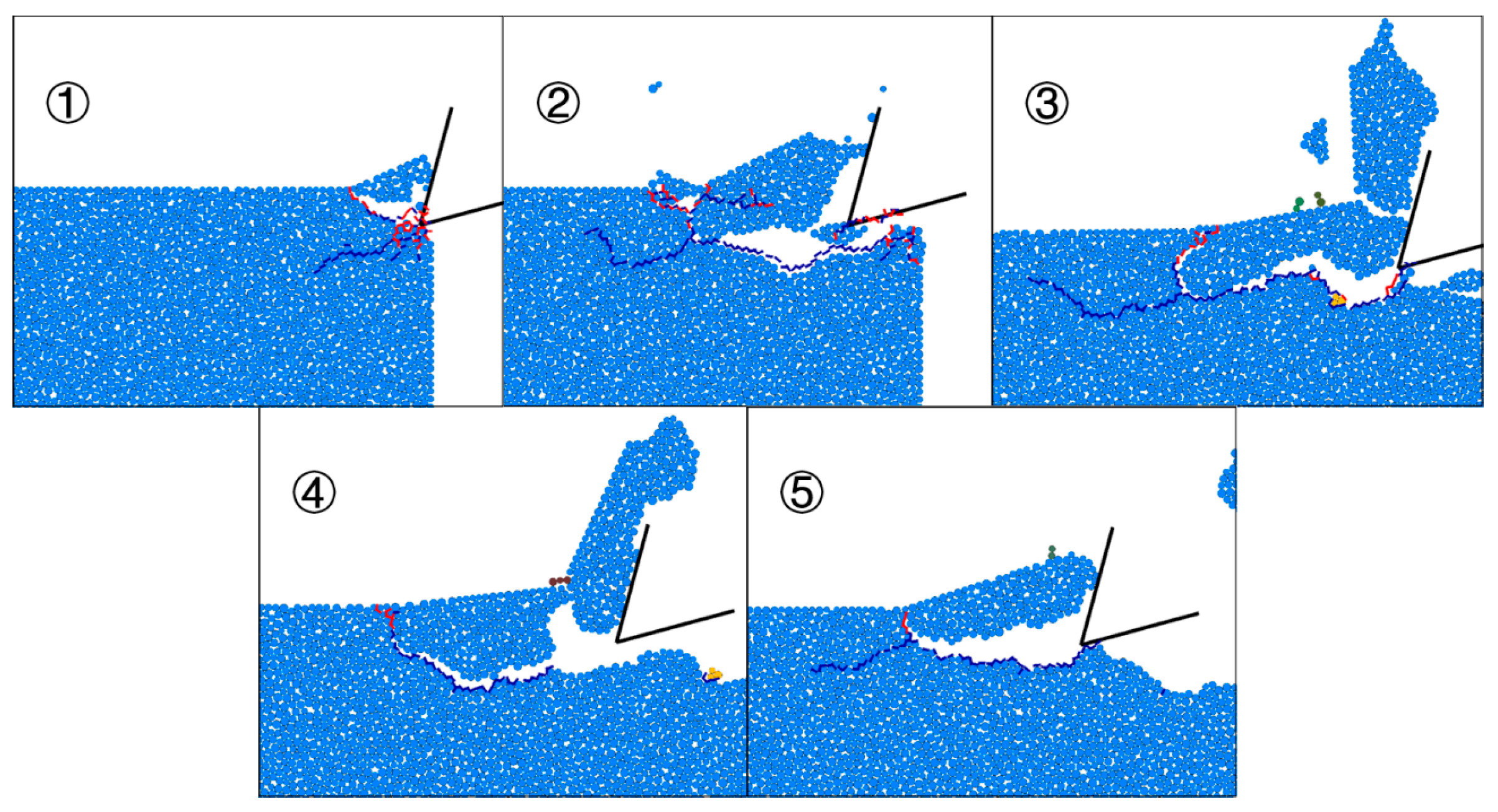
The cutting morphology and fracture propagation in Figure 14, Figure 15 and Figure 16 show that there are two basic causes for the crack initiation. One is the cutting crack generated by the tool intrusion, the other is the cutting crack generated from the failure zone. Shear failure occurred as a result of the shear fracture expanding in the direction of the tool movement and becoming a macroscopic crack. At this time, the cuttings are strip-shaped and semi-exfoliated, which produces tension cracks under the pressure of the cutting tool and rock matrix, then the cuttings spring out under the action of elastic force. This process is distinct from the earlier stated method, through which a fracture makes the cutting.
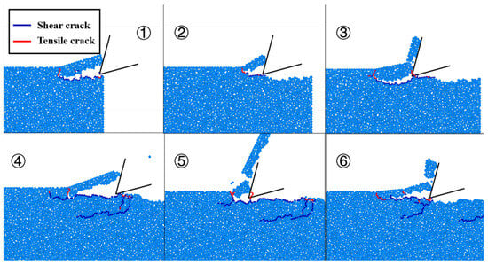
Figure 14.
The Morphology of Cuttings and Crack Propagation Diagram in Continuous Parallel Cutting (DOC = 1.5 mm). Note: The numbers ①–⑥ refer to the chronological order of the cutting tests; the principle of bond breaking is shown in Figure 8 above, blue is shear crack, red is tension crack; the following figure is the same.
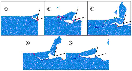
Figure 15.
The Morphology of Cuttings and Crack Propagation Diagram in Continuous Parallel Cutting (DOC = 2.5 mm).

Figure 16.
The Morphology of Cuttings and Crack Propagation Diagram in Continuous Parallel Cutting (DOC = 3.5 mm).
An interesting phenomenon is visible in the image above. The crushing zone resulting from the contact between the front section of the tool and the rock is accompanied by secondary cracks causing damage to the interior of the rock, in addition to the initiation cracks sprouting on the boundary. Moreover, the primary fracture might split in the middle, which can also result in secondary cracks that can also cause harm. According to the simulation results, damage cracks can be classified into two categories. One is to influence the shape and even more of the rock fragmentation after the cutting direction, as shown in Figure 14 (⑤) and Figure 15 (②,③,⑤). The other is damage cracks that do not expand in the direction of cutting velocity towards rock substrate, as shown in Figure 14 (④,⑥), Figure 15 (①), and Figure 16 (①). Next, the characteristics of the rock fragmentation are selected for the process analysis.
3.3.1. Development Process of Fractured Cuttings
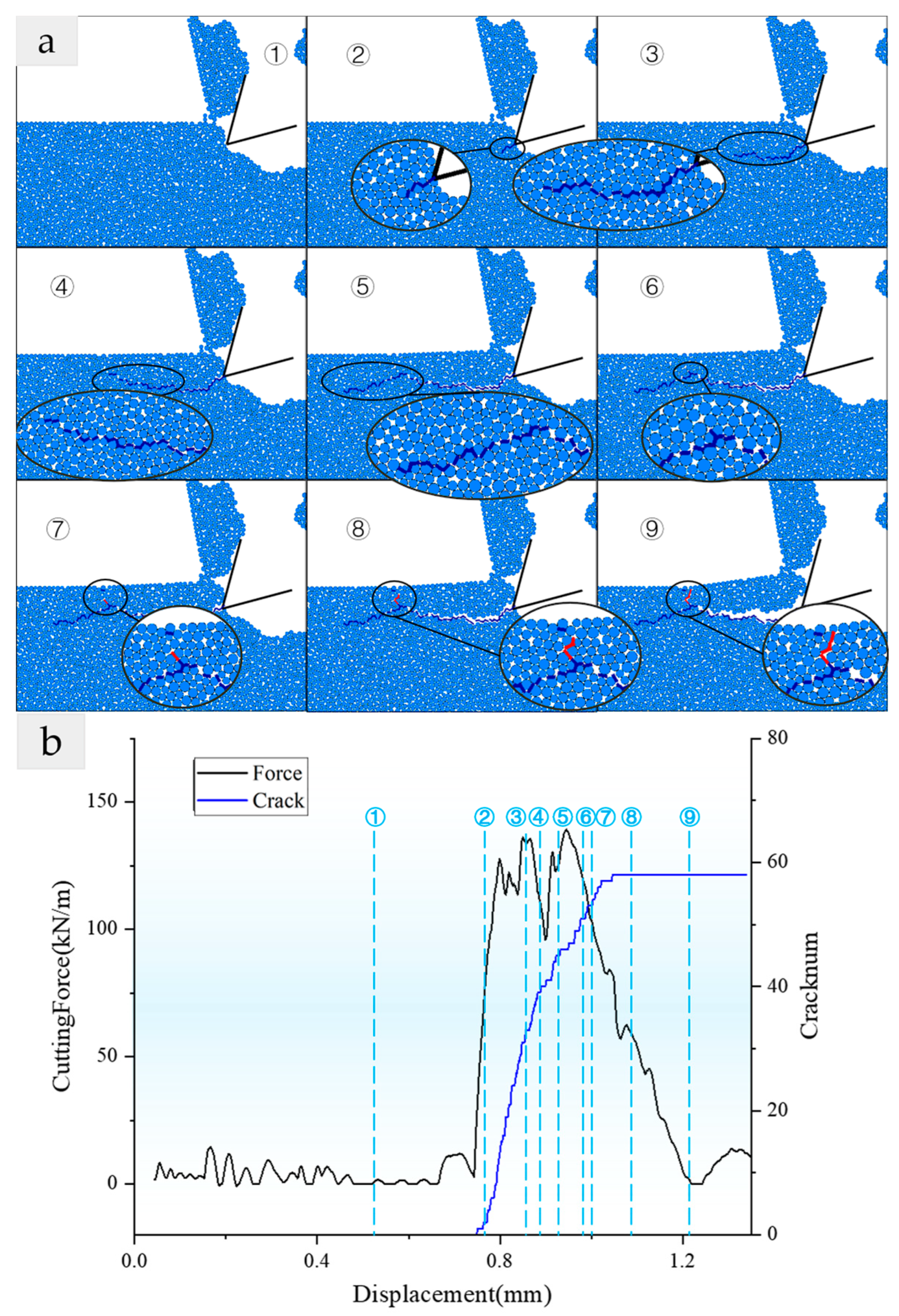
To investigate the development process of fractured cuttings, the fifth fragment (Figure 15 (⑤)) from the DOC = 2.5 mm was selected for the playback of the fracture process, as shown in Figure 17a.
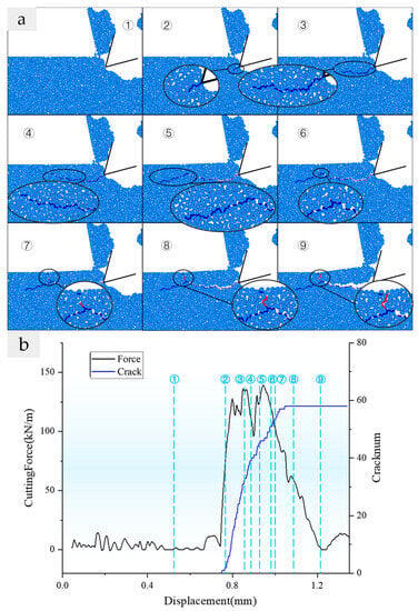
Figure 17.
(a) Development Process of Fractured Cuttings; (b) Fracture-type Cuttings Formation Process Forces and Cracks (Group h3, fifth fragmentation). Note: the numbers ①–⑨ refer to the chronological order of the cutting tests, and the numbers in figures a and b are corresponding; the principle of bond breaking is shown in Figure 8 above, blue is shear crack, red is tension crack; the following figure is the same.
The rake face of the drill teeth first touches the rock, and, with the advancement of the drill teeth, a high-stress zone is created in the contact zone between the drill teeth and the rock (Figure 17a (①,②), in which shear crack occurs without local fracture zone, releasing most of the stress in the high-stress zone. Local shear failure results from the production of a macro-shear crack when the critical value of the macro-crack propagation is achieved (③)).
The primary fracture then extends a distance in the direction of velocity, turning to the rock substrate and extending to the free surface, which formed broad strips of semi-detached fragmentation (④,⑤). Semi-shedding rock fragmentation is compressed by rock substrates and cutters, and secondary cracks emerge from the fragility of the rock chip (⑥,⑦). Semi-exfoliated cuttings further release stress under compression, expanding secondary cracks and extending them to the free surface to form intact rock cuttings (⑧,⑨). This type of failure has comparable experimental evidence in Liu’s research, as illustrated in Figure 17b.
3.3.2. The Development of Damaged Fragmentation
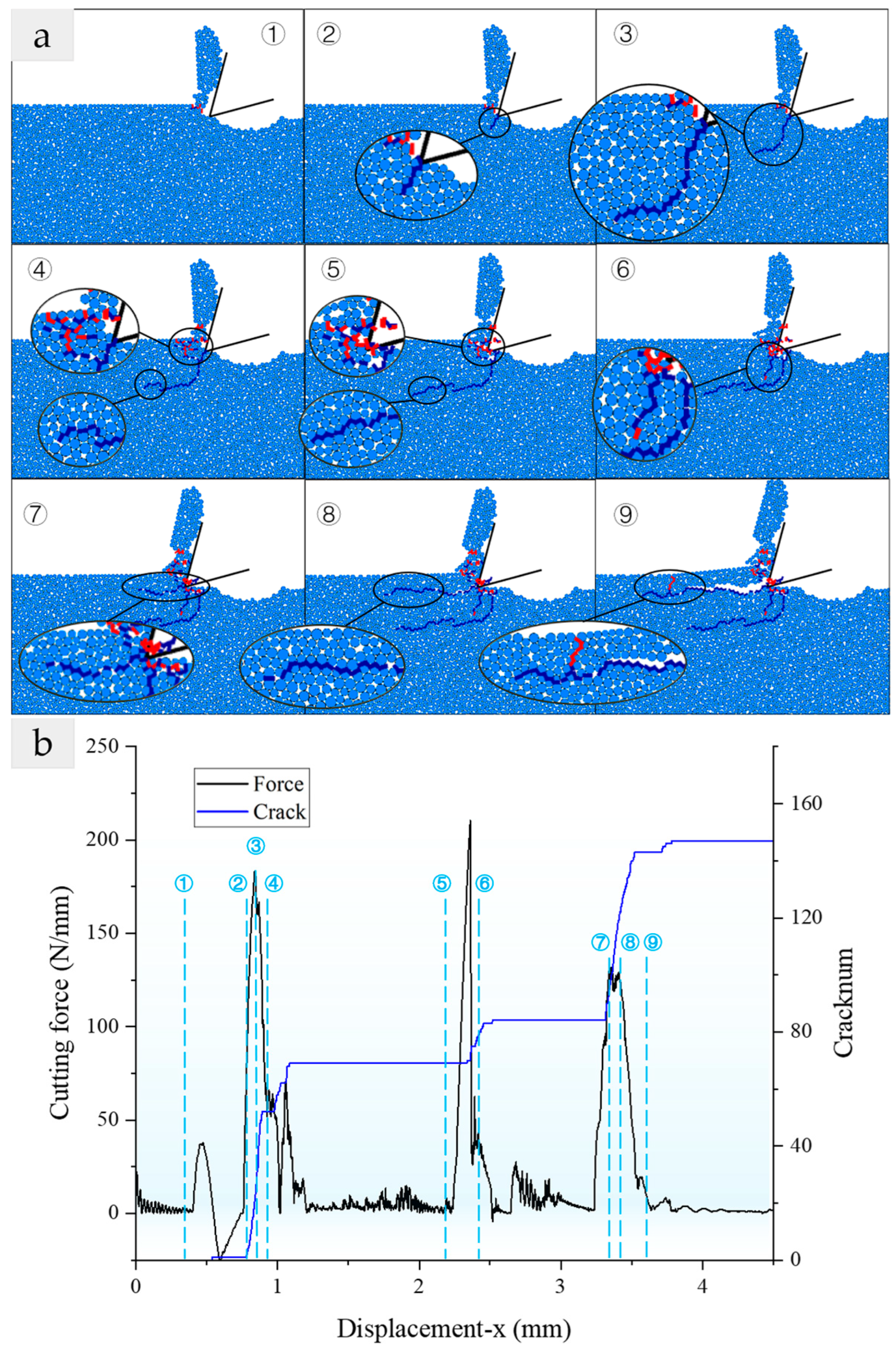
The fourth fragmentation with the condition of DOC = 1.5 mm was selected to play back in PFC. The process of generating fragmentation was similar to conventional damage and fracture damage, except that damage cracks were produced, and there were crush zones and excess crush zones. However, the damage cracks and damage areas are more complex, and the development process of damage-shaped cuttings simulated by the discrete element method is shown in Figure 18a.
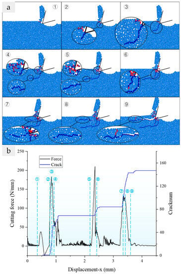
Figure 18.
(a) Development Process of Crack in Damaged Cuttings; (b) Formation Process Force and Crack of Damaged Cuttings. (Group h2, fourth fragmentation).
Damage-shaped damage exhibits identical macroscopic damage crack initiation and expansion phases to other fractures; however, no rock fragmentation is produced. The specific failure process is shown in Figure 18. The high-stress zone is produced in the contact area between the drill teeth and the rock, and the shear crack is formed (①,②). The shear crack propagates to the rock matrix for a certain distance to form the macroscopic damage crack (③), then the tool moves on to form local crushing zones (④,⑤). A damaged crack (⑥) emerged from the crushing area. Shearing fissures then developed along the cutting direction and created semi-shedding rock fragmentation from the crushed zone (⑦). The process of fragmentation formation is similar to that of the conventional one, where semi-detached rock fragmentation is subject to pressure from rock substrates and drill teeth (⑧,⑨). Once the fragmentation is expelled under the influence of elastic force, the tensile failure and tensile fractures expand to the free surface. The region where the damaged crack is located is called the region of damaged failure, and the damaged crack can be regarded as releasing the strain energy of the next cuttings ahead of time in the continuous cutting.
3.4. Conclusion of Failure Type
According to the results of the simulation, the fracture mechanism can be identified based solely on whether or not rock cuttings appear. Damage failures do not result in the shedding of fragmentation; the local area containing the damage failures are the area of damage. The primary crack, which determines the basic shape of the crumbs, is formed from the middle of the main crack, and secondary cracks occur in the process of the main crack. Three kinds of rock fragmentation can develop in this example of rock cutting: conventional failure, fracture failure, and damage failure. The crack propagation caused by three types of fragmentation is summarized as follows:
- Conventional Failure
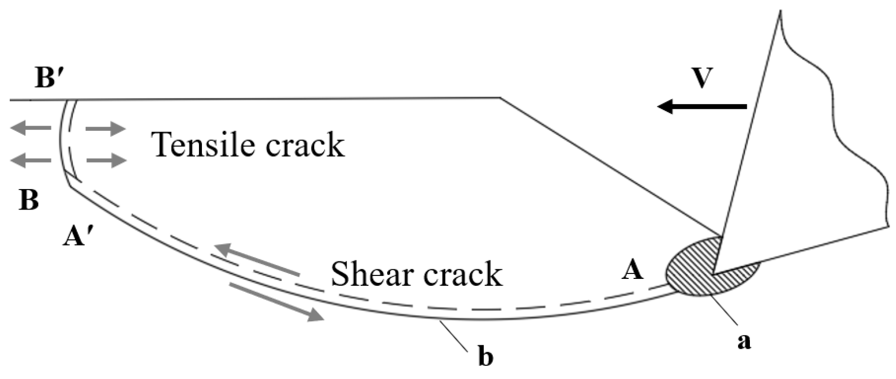
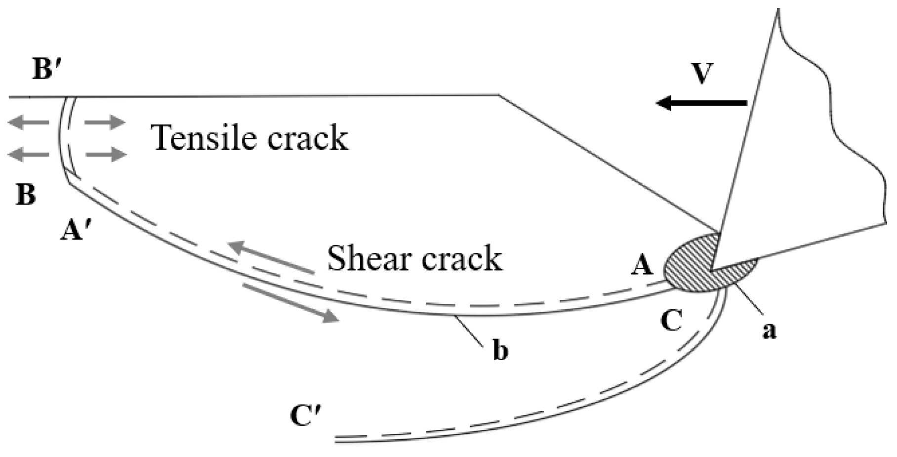
The conventional failure is very similar to the failure with damage cracks, in which a crushing zone a is produced by the tool contacting the rock. The crack will also germinate to the rock matrix and then turn to the free surface, forming an excess crushing zone b. The difference lies in the crack development process.
After the cutter impacts the rock to create a crushing area, as seen in Figure 19, shearing damage fractures appear from the crushing area to create a spindle-like, semi-shedding rock fragmentation, or AA′. Cuttings fall off when the tension crack reaches the free surface because the tension action is exerted from point A′ to the free surface, and the tension crack BB’ is formed from the weak part of semi-detached rock fragmentation. This is because the direction of crack propagation is inconsistent with the direction of velocity. At the time of falling off, cuttings are released from the rock matrix and the drill teeth under compression, i.e., elastic properties of cuttings are ejected.
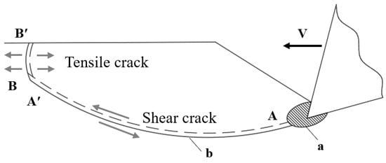
Figure 19.
Development Mechanism of Conventional Failure. Note: a is the crushing area; b is the excess crushing area; AA′ is a macroscopic shear crack; BB′ is a macroscopic tensile crack; the dotted side at the crack represents the fragment area, and the solid line side represents the rock matrix; the opposing arrows represent the extrusion tension; the staggered arrows represent the shear action; the following figure is the same.
- B.
- Fracture Failure
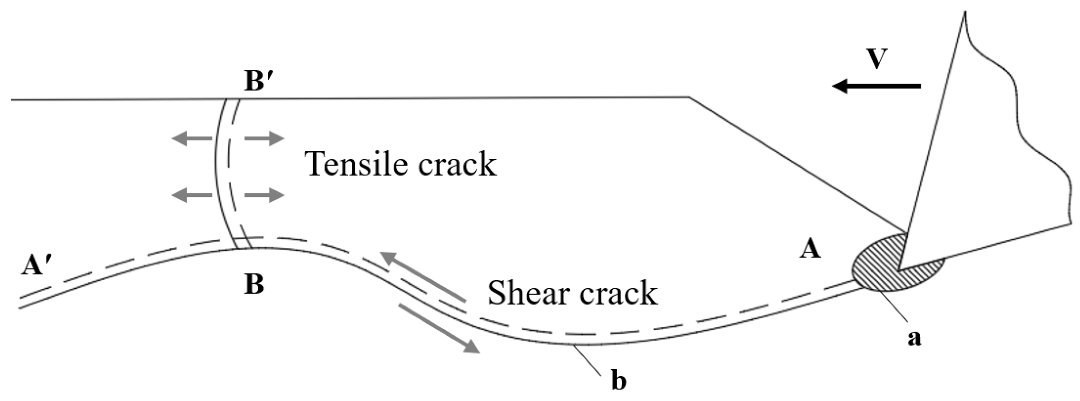
In the simulation and actual experiment, the flaking of rock fragmentation caused by secondary cracks may occur. After the main crack extended from the broken core propagates along the velocity direction for a certain distance, a semi-exfoliated rock fragment is formed, and the secondary crack which sprouts from the middle part of the main crack propagates to the free surface and leads to the exfoliation of rock fragmentation.
As shown in Figure 20, when the tool contacts the rock and with the advancement of the tool, the area of contact between the tool and the rock produces crush zone a. The main shear fracture AA’ is formed when the critical number of macro-crack propagation is attained. The main crack expands some distance in the direction of velocity, followed by a long strip of semi-detached rock fragmentation. At this stage, secondary fracture BB’ formed and spread from weak fragments, as semi-detached rock fragmentation was caused by the action of rock substrates and cutters under pressure. The secondary cracks extend to the free surface, and the semi-exfoliated cuttings are tensioned to form intact rock fragments. The cuttings are ejected to form an excess crushing zone b, and the tool moves forward without substantial resistance until it reaches the rock again to begin the next cut.
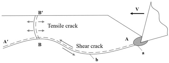
Figure 20.
Development Mechanism of Fracture Failure.
- C.
- Damage Failure
In rock cutting, as depicted in Figure 21, one or more cracks propagate from the crushing zone to the rock matrix to form the damage zone. After the crack propagates for a certain distance, a large amount of strain energy is released in this area, and then the tool moves on to carry out continuous cutting, which is called damage failure. The damage crack of the damage failure will also have a great impact on the subsequent cutting, which is equivalent to the pre-breaking. It released most of the energy, and the PCF in the next cutting process will be much smaller than the undamaged form.
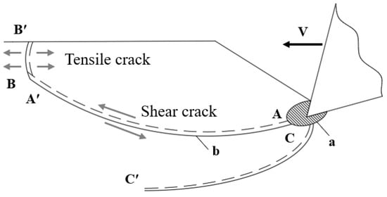
Figure 21.
Development Mechanism of Damage Failure. Note: CC′ is a macroscopic shear crack, the other comments are the same as those used above.
When the tool touches the rock, a crushing zone a appears, and a macroscopic shear crack CC′ propagates from the crushing zone to the rock matrix. The damage crack develops for a distance and then propagates along the direction of tool velocity, but no complete cuttings were formed. Subsequently, with the advancement of the tool, the macro shear crack AA′, which forms cuttings, germinates. The process of the production is similar to that of conventional failure.
CC′ is a macroscopic shear crack propagating along the direction of rock matrix, which can be regarded as releasing the strain energy at the corresponding position ahead of time.
The three types of failure have something in common: (a) All the cuttings first form a long strip of semi-exfoliated cuttings and then produce tensile cracks under compression to form complete cuttings. (b) In the formation of cuttings, the macro-shear crack occurs first, then the tensile crack occurs at the weak point, and, at last, the tensile failure occurs.
4. Conclusions
In this paper, the cutting experiments of cone teeth and the linear cutting simulation of single teeth based on the discrete element software of PFC2D were carried out. The plastic–small fragment-brittle failure stage was reproduced in the experiment, and the debris generation process in the small fragment–brittle failure stage was reproduced in the numerical simulation. From the perspective of size, the rock fragmentation was classified into mini-size fragmentation and normal-size fragmentation, and the generation mechanism of normal-size fragmentation was investigated at different depths. The analysis of the crack forms in rock cutting revealed that the generation process of rock fragmentation can be divided into three categories:
Conventional failure, fracture failure, and damage failure reveal the mechanism of crack development in rock cutting, i.e., macroscopic shear crack is formed first after crack initiation and expansion from the drill tooth tip. Subsequently, semi-detached cuttings are formed, tensile failure occurs, strain energy is released from the cuttings, and damage cracks are formed to extend to the rock matrix. Due to the limited experimental conditions, it is difficult to observe the development of damage cracks, but this phenomenon has been proved in previous studies, and this phenomenon is reproduced by the discrete element method in this paper.
This article summarizes the rock cutting mechanism from the perspective of crack development, which reveals the essence of produce fragment phenomenon and can provide reference for the subsequent research on rock cutting.
Author Contributions
Conceptualization, X.L. and Z.W.; methodology, X.L. and Q.Z.; software, J.M. and H.L.; validation, Z.W. and X.L.; formal analysis, X.L., J.M. and H.L.; investigation, X.L. and J.M.; resources, Q.Z.; data curation, J.M. and H.L.; writing—original draft preparation, J.M.; writing—review and editing, X.L. and Z.W.; visualization, J.M. and H.L.; supervision, X.L.; project administration, X.L.; funding acquisition, X.L. and Q.Z. All authors have read and agreed to the published version of the manuscript.
Funding
This work was supported by the Key Program for International S&T Cooperation Projects of China (2006DFB21300) and the National Natural Science Foundation of China (42072340).
Institutional Review Board Statement
Not applicable.
Informed Consent Statement
Not applicable.
Data Availability Statement
The data that support the findings of this study are available from the corresponding author upon reasonable request.
Conflicts of Interest
The authors declare that they have no known competing financial interests or personal relationships that could have appeared to influence the work reported in this paper.
References
- Barker, J.S. A laboratory investigation of rock cutting using large picks. Int. J. Rock Mech. Min. Sci. Geomech. Abstr. 1964, 1, 519–534. [Google Scholar] [CrossRef]
- Huang, H.; Detournay, E. Intrinsic length scales in tool–rock interaction. Int. J. Geomech. 2008, 8, 39–44. [Google Scholar] [CrossRef]
- Wu, F.Q.; Wu, J.; Qi, S.W. Phenomena and theoretical analysis for the failure of brittle rocks. J. Rock Mech. Geotech. Eng. 2010, 2, 331–337. [Google Scholar] [CrossRef]
- You, M. Strength and damage of marble in ductile failure. J. Rock Mech. Geotech. Eng. 2011, 3, 161–166. [Google Scholar] [CrossRef]
- Huerta, M.; Malkin, S. Grinding of Glass: The Mechanics of the Process. J. Eng. Ind. 1976, 98, 459–467. [Google Scholar] [CrossRef]
- Lin, J.S.; Zhou, Y. Can scratch tests give fracture toughness? J. Eng. Fract. Mech. 2013, 109, 161–168. [Google Scholar] [CrossRef]
- Zhou, Y.; Lin, J.S. On the critical failure mode transition depth for rock cutting. Int. J. Rock Mech. Min. Sci. 2013, 62, 131–137. [Google Scholar] [CrossRef]
- Detournay, E.; Defourny, P. A phenomenological model for the drilling action of drag bits. Int. J. Rock Mech. Min. Sci. Geomech. Abs. 1992, 29, 13–23. [Google Scholar] [CrossRef]
- Detournay, E.; Richard, T.; Shepherd, M. Drilling response of drag bits: Theory and experiment. Int. J. Rock Mech. Min. Sci. 2008, 45, 1347–1360. [Google Scholar] [CrossRef]
- Dai, X.-W.; Huang, Z.-W.; Huang, T.; Chen, P.-J.; Shi, H.-Z.; Yan, S. Experimental investigation on the cuttings formation process and its relationship with cutting force in single PDC cutter tests. J. Precis. Sci. 2023, 20, 1779–1787. [Google Scholar] [CrossRef]
- Bifano, T.G.; Fawcett, S.C. Specific grinding energy as an in-process control variable for ductile-regime grinding. J. Precis. Eng. 1991, 13, 256–262. [Google Scholar] [CrossRef]
- He, X.; Xu, C. Specific energy as an index to identify the critical failure mode transition depth in rock cutting. J. Rock Mec. Rock Eng. 2016, 49, 1461–1478. [Google Scholar] [CrossRef]
- Zhang, H.; Le, J.L.; Detournay, E. An experimental investigation of brittle failure mechanisms in scratch tests of rock. J. Eng. Fract. Mech. 2022, 275, 108827. [Google Scholar] [CrossRef]
- Liu, W.; Zhu, X. Experimental study of the force response and chip formation in rock cutting. Arab. J. Geo. 2019, 12, 457. [Google Scholar] [CrossRef]
- Richard, T.; Detournay, E.; Drescher, A.; Nicodeme, P.; Fourmaintraux, D. The scratch test as a means to measure strength of sedimentary rocks. In Proceedings of the SPE/ISRM Rock Mechanics in Petroleum Engineering, Trondheim, Norway, 8–10 July 1998. [Google Scholar] [CrossRef]
- Cheng, Z.; Sheng, M.; Li, G.; Huang, Z.; Shi, H.; Dai, X.; Guo, Z. Cracks imaging in linear cutting tests with a PDC cutter: Characteristics and development sequence of cracks in the rock. J. Pet. Sci. Eng. 2019, 179, 1151–1158. [Google Scholar] [CrossRef]
- Zeuch, D.H.; Swenson, D.V.; Finger, J.T. Subsurface damage development in rock during drag-bit cutting: Observations and model predictions. In The 24th U.S. Symposium on Rock Mechanics (USRMS); American Rock Mechanics Association: College Station, TX, USA, 1983; pp. 733–742. [Google Scholar] [CrossRef]
- He, X.; Xu, C. Discrete element modelling of rock cutting: From ductile to brittle transition. Int. J. Numer. Anal. Methods Geomech. 2015, 39, 1331–1351. [Google Scholar] [CrossRef]
- Liu, H. Numerical modelling of the rock fragmentation process by mechanical tools. Ph.D. Thesis, Luleå Tekniska Universitet, Luleå, Sweden, 2004. [Google Scholar]
- Liu, W.; Zhu, X.; Jing, J. The analysis of ductile-brittle failure mode transition in rock cutting. J. Pet. Sci. Eng. 2018, 163, 311–319. [Google Scholar] [CrossRef]
- Yang, Y.; Zhang, C.; Lin, M.; Chen, L. Research on rock-breaking mechanism of cross-cutting PDC bit. J. Pet. Sci. Eng. 2018, 161, 657–666. [Google Scholar] [CrossRef]
- Mohammadnejad, M.; Dehkhoda, S.; Fukuda, D.; Liu, H.; Chan, A. GPGPU-parallelised hybrid finite-discrete element modelling of rock chipping and fragmentation process in mechanical cutting. J. Rock Mech. Geotech. Eng. 2020, 12, 310–325. [Google Scholar] [CrossRef]
- Loui, J.P.; Karanam, U.M.R. Numerical Studies on Chip Formation in Drag-Pick Cutting of Rocks. J. Geotech. Geol. Eng. 2012, 30, 145–161. [Google Scholar] [CrossRef]
- Menezes, P.L.; Lovell, M.R.; Avdeev, I.V.; Lin, J.-S.; Higgs, C.F. Studies on the formation of discontinuous chips during rock cutting using an explicit finite element model. J. Adv. Manuf. Technol. 2014, 70, 635–648. [Google Scholar] [CrossRef]
- Zhu, X.; Luo, Y.; Liu, W.; Yang, F.; Li, Z.; Lu, D. Rock cutting mechanism of special-shaped PDC cutter in heterogeneous granite formation. J. Pet. Sci. Eng. 2022, 210, 110020. [Google Scholar] [CrossRef]
- Cundall, P.A.; Strack, O.D.L. A discrete numerical model for granular assemblies. J. Geotech. 1979, 29, 47–65. [Google Scholar] [CrossRef]
- Potyondy, D.O.; Cundall, P.A. A bonded-particle model for rock. Int. J. Rock Mech. Min Sci. 2004, 41, 1329–1364. [Google Scholar] [CrossRef]
- Cho, N.; Martin, C.D.; Sego, D.C. A clumped particle model for rock. J. Int. J. Rock Mech. Min Sci. 2007, 44, 997–1010. [Google Scholar] [CrossRef]
- Zhu, X.; Liu, W.; He, X. The investigation of rock indentation simulation based on discrete element method. KSCE J. Civ. Eng. 2017, 21, 1201–1212. [Google Scholar] [CrossRef]
- Zhou, Y.; Lin, J.S. Modeling the ductile–brittle failure mode transition in rock cutting. J. Eng. Fract. Mech. 2014, 127, 135–147. [Google Scholar] [CrossRef]
- Su, O. Numerical Modeling of Cuttability and Shear Behavior of Chisel Picks. J. Rock Mech. Rock Eng. 2019, 52, 1803–1817. [Google Scholar] [CrossRef]
- Nishimatsu, Y. The mechanics of rock cutting. Int. J. Rock Mech. Min. Sci. Geomech. Abs. 1972, 9, 261–270. [Google Scholar] [CrossRef]
- Li, X.; Wang, S.; Ge, S.; Malekian, R.; Li, Z. A Theoretical Model for Estimating the Peak Cutting Force of Conical Picks. J. Exp. Mech. 2018, 58, 709–720. [Google Scholar] [CrossRef]
- Yasar, S.; Yilmaz, O.A. Drag pick cutting tests: A comparison between experimental and theoretical results. J. Rock Mech. Geotech. Eng. 2018, 10, 893–906. [Google Scholar] [CrossRef]
- Yasar, S. A General Semi-Theoretical Model for Conical Picks. Int. J. Rock Mech. Min. Sci. 2020, 53, 2557–2579. [Google Scholar] [CrossRef]
- Yasar, S. Predictive plots for conical pick performance using mechanical and elastoplastic properties of rocks. J. Rock Mech. Geotech. Eng. 2020, 12, 1027–1035. [Google Scholar] [CrossRef]
- Evans, I. The force required to cut coal with blunt wedges. Int. J. Rock Mech. Min. Sci. Geomech. Abs. 1965, 2, 1–12. [Google Scholar] [CrossRef]
- Evans, I. A theory of the cutting force for point-attack picks. Int. J. Min. Eng. 1984, 2, 63–71. [Google Scholar] [CrossRef]
- Buyuksagis, I.S.; Goktan, R.M. Investigation of marble machining performance using an instrumented block-cutter. J. Mater. Process. Technol. 2005, 169, 258–262. [Google Scholar] [CrossRef]
- Yilmaz, N.G.; Yurdakul, M.; Goktan, R.M. Prediction of radial bit cutting force in high-strength rocks using multiple linear regression analysis. Int. J. Rock Mech. Min. 2007, 44, 962–970. [Google Scholar] [CrossRef]
Disclaimer/Publisher’s Note: The statements, opinions and data contained in all publications are solely those of the individual author(s) and contributor(s) and not of MDPI and/or the editor(s). MDPI and/or the editor(s) disclaim responsibility for any injury to people or property resulting from any ideas, methods, instructions or products referred to in the content. |
© 2023 by the authors. Licensee MDPI, Basel, Switzerland. This article is an open access article distributed under the terms and conditions of the Creative Commons Attribution (CC BY) license (https://creativecommons.org/licenses/by/4.0/).


