Article

Performance Analysis of Dual-Hop DF Multi-Relay FSO System with Adaptive Modulation

by
Wagdy Ameen Alathwary
and
Essam Saleh Altubaishi
*
Department of Electrical Engineering, King Saud University, P.O. Box 800, Riyadh 11421, Saudi Arabia
*
Author to whom correspondence should be addressed.
Appl. Sci. 2023, 13(19), 11035; https://doi.org/10.3390/app131911035
Submission received: 15 September 2023 / Revised: 30 September 2023 / Accepted: 4 October 2023 / Published: 7 October 2023
(This article belongs to the Special Issue Advanced Technologies in Optical and Microwave Transmission)

Abstract

:
The signal quality in high-bandwidth free space optical (FSO) systems deteriorates due to atmospheric turbulence and pointing errors. Employing techniques such as adaptive transmission and relay selection (RS) can mitigate their effects. This paper analyzes the performance of a dual-hop decode-and-forward multi-relay FSO system with an adaptive M-ary phase shift keying scheme. This analysis is based on the recently proposed Fisher–Snedecor  F channel model and considers the impact of pointing errors. We propose two partial relay selection schemes based on the source-to-relay or relay-to-destination channel state information to reduce the complexity of the optimal relay selection scheme. In this investigation, we derive closed-form expressions for the outage probability, modulation level selection probability, and spectral efficiency (SE) and compare the performance of the proposed RS schemes under balanced and unbalanced link cases. We observe an improvement in the SE with an increase in the number of modulation levels and the number of relays. Moreover, it is noted that the performance of the system can be restricted by the quality of either the source-to-relay or the relay-to-destination link, even if the quality of the other link is perfect. Finally, the outcomes obtained through the derived expressions are validated using Monte Carlo simulations.

1. Introduction

Free space optical (FSO) communication systems are gaining substantial attention as a viable solution to fulfill the demanding requirements of upcoming 6G networks. These systems can easily integrate with or complement other technologies, providing numerous potential applications, such as high-speed transmission in backhaul and fronthaul links, satellite communications, and urban and metropolitan areas for last-mile connectivity. Although the FSO system can offer a solution for the increasing demand for high-speed and reliable communication, it can be affected by atmospheric turbulence (AT), which may reduce signal quality and transmission range [1,2].
Numerous models have been proposed in the literature to describe the fading that occurs in the channel of the FSO system due to AT. The most commonly used models are the Log–normal ( LN ), Gamma–Gamma ( GG ), and Málaga ( M ) distribution models. It has been observed that GG and M are the most appropriate distributions to represent conditions ranging from weak to strong turbulence, whereas the LN distribution is primarily useful for weak turbulence conditions. In a recent work, the authors of [3] conducted a study to assess the feasibility of utilizing the Fisher–Snedecor F distribution for AT in the FSO channel. The findings of their study revealed that the F distribution offers a fit to experimental data that is as good as or superior to that of the GG distribution.
In order to address the effect of AT along with other issues, such as long-distance links and no direct link between the transmitter and the receiver, relaying techniques have been introduced in FSO systems as an efficient solution. These techniques also aim to increase spatial diversity. The most popular relaying strategies, which have been discussed in the literature are the decode-and-forward (DF) and amplify-and-forward (AF). The single relaying technique (dual-hop) has been widely studied in FSO networks, including those integrated with other technologies. A dual-hop FSO system was considered with an AF scheme in [4] and with a DF scheme in [5] over F and M channels, respectively. In [6], the authors presented an AF-based high-altitude platform station (HAPS) FSO system over a GG channel. Using unmanned aerial vehicles (UAVs) as a relay in a dual-hop FSO system was considered in [7]. Furthermore, many works have studied the integration of FSO with radio frequency (RF) communication, for various applications, such as terrestrial, airborne, and satellite communication [8,9,10,11]. Other studies have investigated the integration of FSO with underwater wireless optical communication [12,13,14] and power line communication (PLC) [15]. In a multi-relay system, parallel relays are employed between the transmitter and receiver, either with or without an existing direct link. This configuration was investigated in [16,17,18,19]. In these works, all the relays were active during transmission, which required precise synchronization between these relays.
Relay selection (RS), which is based on channel condition, is a method that chooses the relay with the best signal-to-noise ratio (SNR) to forward the data to destination. It was proposed in cooperative FSO systems to enhance resource utilization and eliminate the need for complex relay synchronization [20]. In [21], the average bit error rate (ABER) expression of the DF cooperative FSO system was derived. The cooperative system was further investigated in [22], where the exact expressions of outage probability (OP) and ABER were derived as well as the asymptotic expressions. In these works, the optimal relay selection (ORS) scheme was used to select the best relay. This scheme improves the system’s performance but requires the channel state information (CSI) of all hops. To reduce this complexity as well as the consuming power, a proposed solution known as the partial relay selection (PRS) scheme was introduced. Within this scheme, RS is dependent on CSI of either the source-to-relay or relay-to-destination links. The most comprehensive work in RS cooperative FSO systems was introduced in [23], where the ABER of the cooperative system with ORS and PRS schemes have been investigated over LN and GG channel models. In [24], the PRS scheme was also proposed for a two-way relay FSO system, and its performance was investigated in terms of OP.
Another technique to mitigate the impact of AT in FSO systems is adaptive transmission. This approach involves dynamically adjusting the transmission parameters, such as modulation order and transmitted power, based on the channel conditions. Adaptive modulation (AM), for instance, adapts the modulation order depending on the channel conditions. This adaptation improves spectral efficiency (SE) of the system while achieving the required target performance in terms of ABER or OP. On the other hand, transmitted power control can be employed to regulate transmitted power according to received signal levels, thereby improving the SNR and reducing the effect of AT. In [25], the authors investigated the channel capacity of an FSO system over an M channel with truncated channel inversion with fixed rate adaptive transmission. They extended the analysis based on optimal rate, optimal power and rate, and channel inversion with fixed rate adaptive transmission in [26]. The authors in [27] proposed a link adaptation algorithm using M-ary pulse position modulation (PPM) over an LN fading channel to improve the bandwidth efficiency by varying the code rate and modulation order. Enhancement of the SE of the FSO system while maintaining the target ABER was achieved using the AM technique in [28,29,30,31,32]. The performance analysis of the AM for a subcarrier intensity modulation (SIM) system utilizing phase shift keying (PSK) was presented in [28]. The analysis specifically focused on single-input single-output (SISO) systems over the LN and GG channels, and subsequently extended to multiple-input multiple-output (MIMO) systems. The analysis in [28] was extended to include PSK and quadrature amplitude modulation (QAM) over a GG channel in [29]. The performance of the AM for SIM systems utilizing PSK modulation and M-ary differential PSK modulation was studied over an M channel, respectively, in [30,31], where a SISO configuration was considered in [30] and an MIMO configuration was considered in [31]. Recently, in [32], we investigated the performance of a coherent parallel-branch maximum ratio combining system with adaptive M-PSK modulation over GG channels. The authors in [33] proposed a method to improve the SE with maintaining the target OP. They investigated multiple-input single-output (MISO) and single-input multiple-output (SIMO) adaptive coherent systems employing PSK or QAM over an LN channel. The authors extended the work and investigated AM for the intensity modulation/direct detection (IM/DD) system with PPM and pulse amplitude modulation (PAM) in [34]. On the other hand, the integration of adaptive transmission with relay-assisted FSO systems has received little attention. In [35], the authors proposed the use of AM in a multi-hop coherent FSO system (i.e., multi-relays are serially placed between the source and the destination) with an AF scheme. The OP, SE, and ABER were derived over an M channel with pointing errors. Additionally, [36] suggested adjusting the transmitted power over an LN channel to enhance bandwidth efficiency in a multi-hop FSO system with a DF scheme.
Motivated by these observations, the performance of a dual-hop DF multi-relay system that employs PSK modulation is investigated under SIM detection. All hops are assumed to follow an F turbulence channel with pointing errors. To enhance the performance of the considered system, AM and the RS techniques are presented. In addition to the ORS scheme, two sub-optimal schemes are proposed. In the first scheme, RS is based on the source-to-relay CSI, while in the second scheme, it relies on the relay-to-destination CSI. These sub-optimal schemes reduce complexity and power consumption compared to the optimal scheme. In order to analyze the system performance, expressions for the cumulative distribution functions (CDFs) of the received SNRs are derived for both optimal and sub-optimal schemes. Based on these derived CDF expressions, we present the performance analytical expressions in terms of OP, SE, and modulation level selection probability. The system’s performance is analyzed under two scenarios: a balanced case where the distances between hops are equal, and an unbalanced case where the distances between hops are unequal. The correctness of the obtained expressions is confirmed using Monte Carlo (MC) simulations.
The rest of this work is summarized as follows. Section 2 describes the system model. Section 3 presents the mechanism of AM. In Section 4 and Section 5, we introduce the performance analysis of single- and multi-relay systems. Section 6 discusses the numerical results, where the performance metrics are presented and the findings are analyzed. Finally, in Section 7, we conclude the paper with a summary.

2. Description of the System

The considered cooperative system consists of a source (S), a destination (D), and L DF relays, R l , l { 1 , , L } without a direct link between the source and destination. The source is equipped with L apertures and has the ability to control the transmission from them, and the relay decodes and retransmits the received signal to the destination. It is assumed that the channel gains of all hops follow F distribution; then, the PDF of F turbulence with pointing error impairment of individual hop can be expressed as [37]
f I j , l I = ξ j , l 2 I Γ ( a j , l ) Γ ( b j , l ) G 2 , 2 2 , 1 a j , l b j , l 1 A o j , l I 1 b j , l , 1 + ξ j , l 2 a j , l , ξ j , l 2 ,
where Γ · is the gamma function, G · , · · , · · is the Meijer G function, j represents the first or the second hop of the l th branch, j { s , d } , ξ j , l 2 and A o j , l are parameters to describe the pointing error impairment, and a j , l and b j , l are the fading parameters where more details about these parameters can be found in [3].
For SIM, the instantaneous SNR, γ j , l , of individual hop is given by γ j , l = ( γ ¯ j , l / A o j , l 2 h j , l 2 ) I j , l 2 , where γ ¯ j , l is the average SNR (ASNR) and h j , l = ξ j , l 2 / ( ξ j , l 2 + 1 ) . Using the variable transformation, the PDF of γ j , l can be written as
f γ j , l γ = ξ j , l 2 2 γ Γ ( a j , l ) Γ ( b j , l ) G 2 , 2 2 , 1 a j , l h j , l b j , l 1 γ γ ¯ j , l 1 2 1 b j , l , 1 + ξ j , l 2 a j , l , ξ j , l 2 ,
and the CDF of F turbulence with pointing errors can be obtained using Equation (2.24.2/2) in [38]. With some operations, it can be expressed as
F γ j , l γ = ξ j , l 2 Γ ( a j , l ) Γ ( b j , l ) G 3 , 3 2 , 2 a j , l h j , l b j , l 1 γ γ ¯ j , l 1 2 1 , 1 b j , l , 1 + ξ j , l 2 a j , l , ξ j , l 2 , 0 .
The CDF can also be obtained using Equation (2.24.2/3) in [38], and represented as follows:
F γ j , l γ = 1 F ¯ γ j , l γ = 1 ξ j , l 2 Γ ( a j , l ) Γ ( b j , l ) G 3 , 3 3 , 1 a j , l h j , l b j , l 1 γ γ ¯ j , l 1 2 1 b j , l , 1 + ξ j , l 2 , 1 0 , a j , l , ξ j , l 2 ,
where F ¯ γ j , l · is the complementary CDF of γ j , l .

3. Adaptive Modulation Technique

The primary aim of implementing the AM technique is to maximize the rate of data transmission over the channel while maintaining constant transmitted power. This technique works by monitoring the channel conditions and measuring the received SNR, then determining the most suitable modulation level, M, that satisfies the target ABER, P o . In particular, the receiver compares the received SNR to N of the predetermined boundaries set, and chooses the modulation level, which is associated with the range of the specific boundaries. For the adaptive M-ary PSK (M-PSK) system, this process can be expressed mathematically as follows:
M = M i = 2 i if γ i γ < γ i + 1 , i = 1 , , N .
The region boundaries { γ i } are set to satisfy P o over the AWGN channel, where the conditional bit error rate is given by [28]
P b M , γ = α m Q 2 γ β m ,
where α m = { 1 , 2 log 2 M } and β m = { 1 , sin π M } for binary PSK (BPSK) and M-PSK, respectively. Taking the inverse of (6), the region boundaries { γ i } are given as
γ 1 = 1 2 Q 1 P 0 2 ,
γ i = 1 2 β m 2 ( i ) Q 1 P 0 α m ( i ) 2 , i = 2 , , N ,
γ N + 1 ,
where Q 1 · is the inverse Q function.

4. The Performance Analysis of Dual-Hop Single-Relay System

We assume that there is only one transmitter aperture and one DF relay R l , where the receiver uses the received instantaneous SNR to adjust the data rate. In this case, the received end-to-end (e2e) SNR of the system is limited by the minimum SNR of the individual hop. Therefore, the e2e SNR can be expressed by
γ l = m i n γ s , l , γ l , d ,
where γ s , l is the SNR of the S- R l link and γ l , d is the SNR of the R l -D link. The CDF of γ l can be written as
F γ l γ = F γ s , l γ + F γ l , d γ F γ s , l γ F γ l , d γ .
Using (4), the CDF of γ i can be represented by
F γ l γ = 1 F ¯ γ s , l γ F ¯ γ l , d γ = 1 F ¯ γ l γ ,
where the complementary CDF of γ l is given by
F ¯ γ l γ = ξ s , l 2 ξ l , d 2 Γ ( a s , l ) Γ ( b s , l ) Γ ( a l , d ) Γ ( b l , d ) G 3 , 3 3 , 1 a s , l h s , l b s , l 1 γ γ ¯ s , l 1 2 1 b s , l , 1 + ξ s , l 2 , 1 0 , a s , l , ξ s , l 2 × G 3 , 3 3 , 1 a l , d h l , d b l , d 1 γ γ ¯ l , d 1 2 1 b l , d , 1 + ξ l , d 2 , 1 0 , a l , d , ξ l , d 2 .

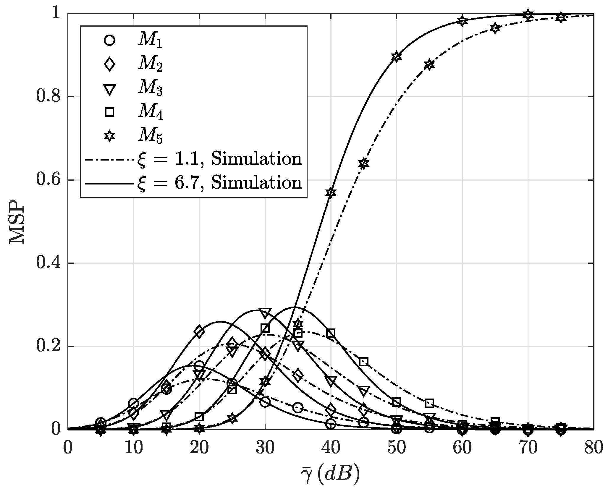
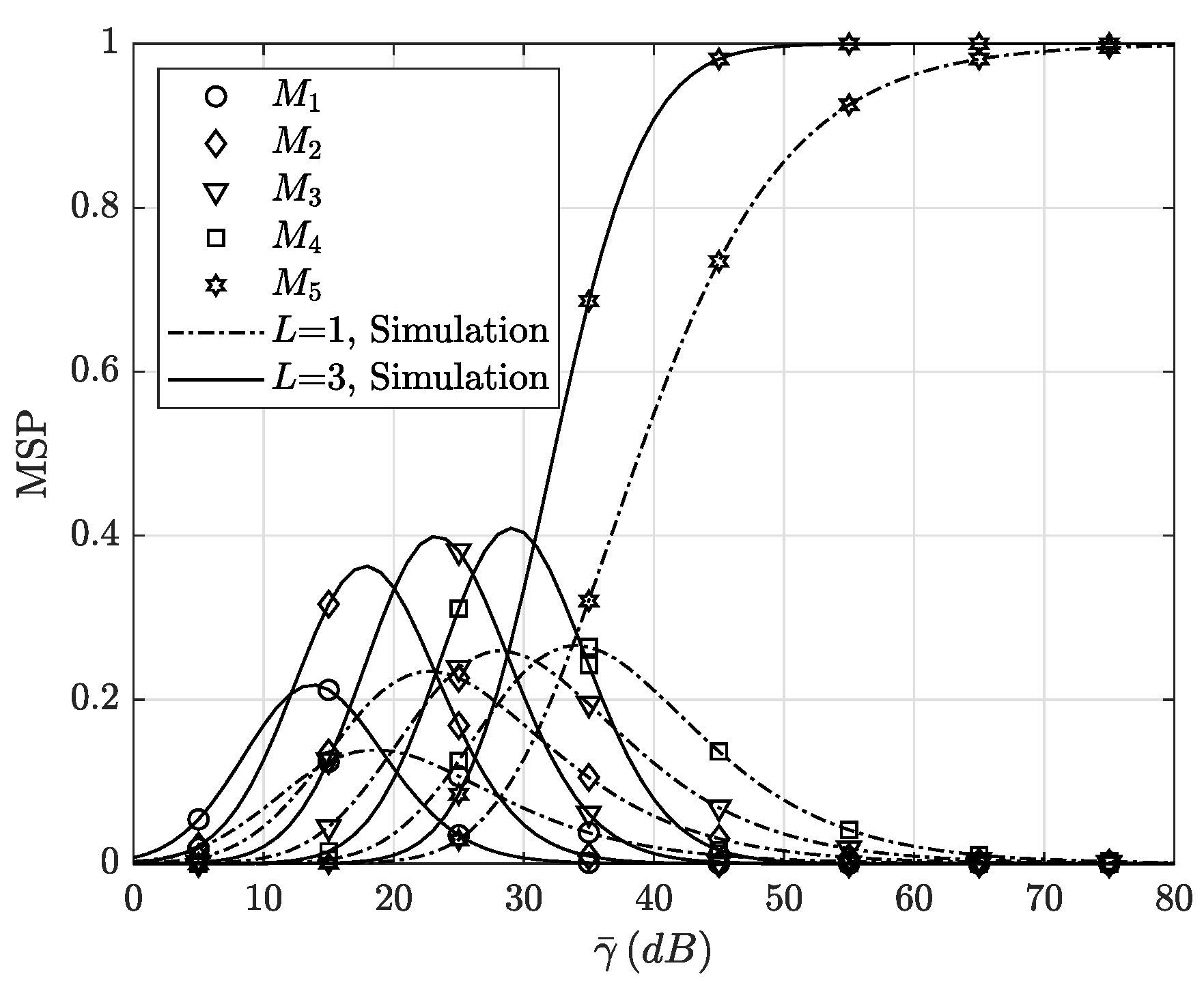
4.1. Modulation Level Selection Probability

Modulation level selection probability (MSP) is an interesting performance metric that shows the behavior of the adaptive system in selecting the modulation level which depends on the received SNR. The modulation level selection probability can be expressed as
P m s ( i ) = P r { γ i γ l < γ i + 1 } = F γ l γ i + 1 F γ l γ i , i = 1 , , N 1 F ¯ γ l γ i , i = N .
Note that F γ l γ N + 1 1 .

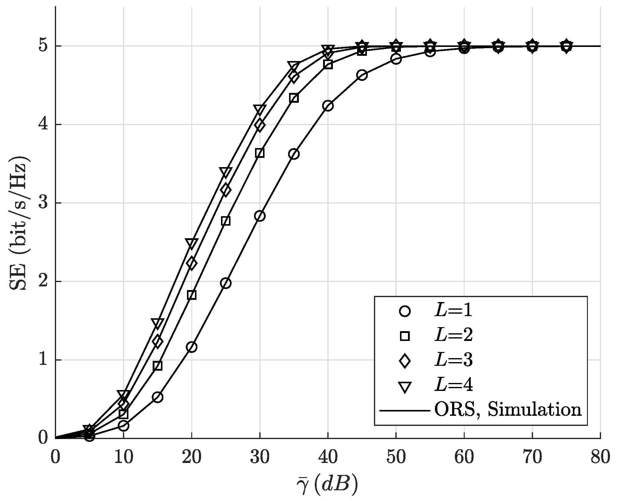
4.2. Spectral Efficiency

SE provides a measure of the system’s capacity which is the amount of information transmitted over a given bandwidth. In the context of the adaptive discrete rate, it represents the ratio of the transmission bit rate ( R b ) to the bandwidth (W), which is expressed by [29]
S = R b W = i = 1 N a i log 2 M i = i = 1 N i a i ,
where
a i = P r { γ i γ l < γ i + 1 } = γ i γ i + 1 f γ l γ d γ = F γ l γ i + 1 F γ l γ i .
The SE of the dual-hop single-relay (DH-SR) system can be then given as
S = i = 1 N i [ F γ l γ i + 1 F γ l γ i ] = N i = 1 N F γ l γ i = i = 1 N F ¯ γ l γ i .

4.3. Outage Probability

The OP is a crucial performance metric to evaluate the quality and reliability of communication systems. It represents the probability that the instantaneous SNR falls below a predefined threshold due to the channel impairments. In the considered system, there is no transmission when the e2e SNR falls below γ 1 , which is represented as follows:
P o u t = P r { γ l < γ 1 } = 0 γ 1 f γ l γ d γ = F γ l γ 1 .

5. The Performance Analysis of Dual-Hop Multi-Relay System

Here, we focus on analyzing the performance of the considered dual-hop multi-relay (DH-MR) system with AM. In this system, only one relay is selected to transmit the data based on a specific RS scheme. If γ t represents the received SNR of the adaptive DH-MR system after applying the selection protocol, the modulation level of the system is chosen based on P o and γ t as
M = M i = 2 i if γ i γ t < γ i + 1 , i = 1 , , N .
For this system, the modulation level selection probability is given by
P m s s c ( i ) = P r { γ i γ t < γ i + 1 } = F γ t γ i + 1 F γ t γ i , i = 1 , , N 1 1 F γ t γ i , i = N .
The SE of the adaptive DH-MR system with RS can be expressed in a manner analogous to the adaptive DH-SR system, as follows:
S s c = R b W = i = 1 N b i log 2 M i = i = 1 N i b i ,
where
b i = P r { γ i γ t < γ i + 1 } = γ i γ i + 1 f γ t γ d γ = F γ t γ i + 1 F γ t γ i .
The SE of the DH-MR system can be represented as
S s c = i = 1 N i [ F γ t γ i + 1 F γ t γ i ] = N i = 1 N F γ t γ i .
The OP of the adaptive DH-MR system occurs when γ t falls below γ 1 , hence
P o u t s c = P r { γ t < γ 1 } = 0 γ 1 f γ t γ d γ = F γ t γ 1 .
The CDF of γ t , F γ t · , dependes on the used RS protocol. Therefore, before obtaining expressions for the performance measures, we first need to derive the CDFs of the three RS schemes.

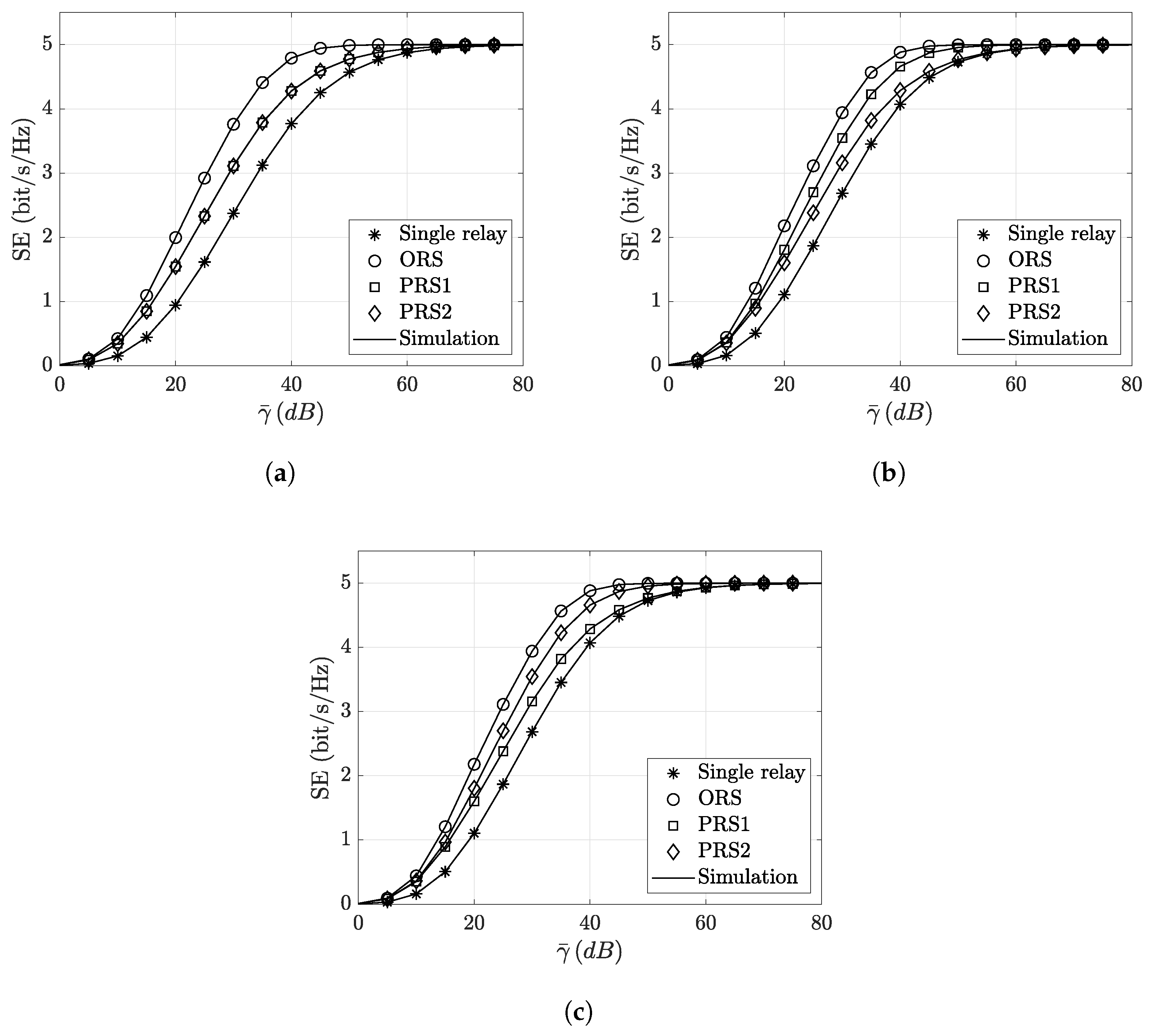
5.1. Optimal Relay Selection Scheme: S-R-D Link

The ORS scheme maximizes the instantaneous SNR at the receiver by selecting the best relay based on CSI of S- R l -D links. The best relay (k) is selected by
k = arg max l { γ l } ,
where γ l is defined in (10). The e2e SNR, γ o p , under the ORS scheme is given by
γ o p = max l { γ l } .
Since all hops follow F distribution, the CDF of γ o p is written as a product of CDFs of an individual branch as follows:
F γ o p γ = l = 1 L F γ l γ = l = 1 L 1 F ¯ γ l γ = 1 i 1 = 1 L F ¯ γ i 1 γ + i 1 = 1 L 1 i 2 = i 1 + 1 L F ¯ γ i 1 γ F ¯ γ i 2 γ + + 1 L 1 i 1 = 1 L ( L 2 ) i 2 = i 1 + 1 L ( L 3 ) i L 1 = i L 2 + 1 L F ¯ γ i 1 γ F ¯ γ i 2 γ F ¯ γ i L 1 γ + 1 L i 1 = 1 L ( L 1 ) i 2 = i 1 + 1 L ( L 2 ) i L = i L 1 + 1 L F ¯ γ i 1 γ F ¯ γ i 2 γ F ¯ γ i L γ .
The CDF can be represented in a short form as follows:
F γ o p γ = 1 + l = 1 L 1 l l F ¯ γ l n γ ,
where
l = i 1 = 1 L ( l 1 ) i 2 = i 1 + 1 L ( l 2 ) i l 1 = i l 2 + 1 L 1 i l = i l 1 + 1 L ,
and F ¯ γ l n γ = n = 1 l F ¯ γ i n γ . In the case of identical branches, the CDF of γ o p is given by
F γ o p γ = 1 F ¯ γ l γ L = l = 0 L 1 l L l F ¯ γ l l γ .

5.2. Suboptimal Relay Selection Scheme: S-R Link

The ORS scheme is the best selection scheme; however, it requires full knowledge of CSI of all hops. In order to reduce the complexity and power consumption, we introduce the first partial relay selection (PRS1) scheme, which maximizes the instantaneous SNR by selecting the best relay based on CSI of S- R l links. Mathematically, the best relay, k, is selected by
k = arg max l { γ s , l } ,
and the e2e SNR, γ s 1 , under the PRS1 scheme is given by
γ s 1 = min { max l { γ s , l } , γ k , d } ,
where γ k , d is the SNR of the R-D link of the selected k relay. For this scheme, the CDF of γ s 1 can be expressed by
F γ s 1 γ = F γ m 1 γ + F γ k , d γ F γ m 1 γ F γ k , d γ = F γ k , d γ + F γ m 1 γ F ¯ γ k , d γ ,
where F γ m 1 γ = l = 1 L F γ s , l γ , F γ k , d · is the CDF of γ k , d , and F ¯ γ k , d · is the complementary CDF of γ k , d .

5.3. Suboptimal Relay Selection Scheme: R-D Link

The second partial relay selection (PRS2) scheme maximizes the instantaneous SNR by selecting the best relay, k, based on CSI of R l -D links, i.e.,
k = arg max l { γ l , d } ,
and the e2e SNR, γ s 2 , under the PRS2 scheme is given by
γ s 2 = min { γ s , k , max l { γ l , d } } ,
where γ s , k is the SNR of the S-R link of the selected k relay. The CDF of γ s 2 can be expressed by
F γ s 2 γ = F γ s , k γ + F γ m 2 γ F γ s , k γ F γ m 2 γ = F γ s , k γ + F γ m 2 γ F ¯ γ s , k γ ,
where F γ m 2 γ = l = 1 L F γ l , d γ , F γ s , k · is the CDF of γ s , k , and F ¯ γ s , k · is the complementary CDF of γ s , k .
To calculate the performance of the three RS schemes in terms of modulation level selection probability, SE and OP replace F γ t · in (20), (23) and (24) by F γ o p · for the ORS scheme, by F γ s 1 · for the PRS1 scheme, and by F γ s 2 · for the PRS2 scheme.

6. Numerical Results

This section presents selected numerical results for adaptive system performance along with MC simulations. To gain insights into the impact of fading parameters on system performance, different cases are assumed under various turbulence conditions, as shown in Table 1. We also consider various pointing errors, set P o = 10 5 , and assume that γ ¯ s , l = γ ¯ l , d = γ ¯ .
The performance of the adaptive dual-hop single-relay (DH-SR) system is depicted in Figure 1, showcasing the SE across varying turbulence conditions, including strong, moderate, and weak turbulence. These analytical results are obtained using (17), and are plotted for the balanced case vs. the ASNR, γ ¯ , with two different numbers of modulation levels, N = 3 , and N = 5 . It can be seen that the SE improves with increasing γ ¯ . Furthermore, the SE improves with the enhancement of the channel conditions (i.e., the turbulence condition becomes lower) and with an increase in the number of modulation levels. Moreover, Figure 1 illustrates a comparison of the SE for the adaptive DH-SR system under various pointing errors, where ξ = 1.1 refers to the strong pointing errors, while ξ = 6.7 refers to the weak pointing errors. The results clearly show that the adaptive DH-SR system achieves higher SE under weak pointing errors. This indicates that both turbulence conditions and pointing errors significantly impact SE performance and must be considered in the analysis of adaptive systems.
The modulation level selection probability of the adaptive DH-SR system, provided in (14), is illustrated in Figure 2. It is investigated under strong turbulence with two pointing errors and number of modulation levels, N = 5 . It can be observed that at the lowest ASNR values, the modulation level selection probability is low where the OP of the adaptive DH-SR system is high. With increasing the values of the ASNR, a higher modulation level selection probability increases. For the higher values of the ASNR, the largest modulation level, M 5 , dominates the selection process. This observation explains how the SE improves with increasing the values of the ASNR until it reaches its maximum at higher values. In same figure, the impact of the pointing errors on the modulation level selection probability is also illustrated. It is depicted that the modulation level selection probability of all levels decreases significantly with strong pointing errors, ξ = 1.1 , which leads also to a reduction in the SE. This behavior is expected since the strong pointing errors reduce the received SNR, and this, in turn, decreases the modulation level selection probability and the SE.
The SE of the adaptive DH-MR system under three RS schemes given in (23) is presented in Figure 3 and Figure 4. The SE for the balanced case of the adaptive DH-MR system improves as the number of relays, L, increases as shown in Figure 3. This improvement can be attributed to the fact that a larger value of L increases the chance of selecting the relay with better channel gain. However, it is worth noting that the improvement in SE is not linear with the increase in L, indicating that larger values of L may not necessarily lead to further enhancements. This observation underscores the significance of our investigation in determining the optimal number of relays for such system.
The comparison of the SE of the adaptive DH-MR system for three selection schemes is shown in Figure 4. The comparison is provided for three cases: balanced, unbalanced-1, and unbalanced-2 under strong turbulence conditions. Additionally, ξ 1 = ξ 2 = 1.1 for both hops of the balanced case, ξ 1 = 1.1 , ξ 2 = 6.7 for the first and the second hop of the unbalanced-1 case, and ξ 1 = 6.7 , ξ 2 = 1.1 for the first and the second hop of the unbalanced-2 case. It is observed that the SE of the adaptive system under the ORS scheme is the best in all cases. In the balanced case, both PRS schemes, PRS1 and PRS2, exhibit the same performance due to identical channel gains in both hops. Moreover, the PRS1 scheme outperforms the PRS2 scheme in the unbalanced-1 case, while the opposite occurs in the unbalanced-2 case. This difference in the performance can be attributed to the nature of the channel gains and the selection schemes employed in these cases. In the unbalanced-1 case, the turbulence conditions are stronger in the first hops compared to the second hops. Therefore, the PRS1 scheme, in which RS depends on the CSI of the first hop, performs better than the PRS2 scheme, in which RS depends on the CSI of the second hop, as both schemes rely on the minimum capacity of the hops of the selected relay. Conversely, in the unbalanced-2 case, the turbulence conditions are weaker in the first hops compared to the second hops. Consequently, the PRS2 scheme outperforms the PRS1 scheme in this scenario.
Figure 5 shows the modulation level selection probability for the balanced cases of the adaptive DH-MR system under moderate turbulence conditions and strong pointing errors, ξ = 1.1 . The modulation level selection probability of both adaptive DH-MR and adaptive DH-SR systems is compared under the ORS scheme, which gives us more insights into the impact of increasing the number of relays, L, on the SE. For all modulation levels, M i , we can see that the modulation level selection probability of the adaptive DH-MR system is higher than that of the adaptive DH-SR system and its maximum values are shifted to the left compared to the adaptive DH-SR system. This is because increasing L improves the e2e-received SNR, leading to the selection of a higher modulation level for transmission. In other words, the improvement of the received SNR increases the modulation level selection probability.
In Figure 6, we present the OP of the adaptive DH-MR system under three RS schemes along with the OP of the adaptive DH-SR system. The OP is investigated under different cases with strong turbulence conditions. The results indicate improvements in the OP of the adaptive DH-MR system compared to the adaptive DH-SR system, especially for the ORS scheme in all cases, the PRS1 scheme in the unbalanced-1 case, and the PRS2 scheme in the unbalanced-2 case. For other cases, the PRS2 scheme in the unbalanced-1 case and the PRS1 scheme in the unbalanced-2 case, there is only a little improvement in low ASNR values, which confirms the discussion of Figure 4.

7. Conclusions

In this work, the SE of dual-hop DF single- and multi-relay systems with AM was obtained. Moreover, other performance metrics, in terms of modulation level selection probability and OP, were derived. ORS and PRS schemes were introduced, where the ORS scheme requires the CSI of all hops and the PRS scheme requires only the CSI of the source-to-relay or relay-to-destination link. The system’s performance was studied under balanced and unbalanced cases of dual-hop links. The results showed that in addition to other metrics, modulation level selection probability offers more ability to track and understand the behavior of the AM systems. Additionally, it was noticed that the ORS scheme enhances the SE to a greater extent than the PRS schemes, especially when the number of relays and the modulation levels are higher. We also noticed that although PRS schemes reduce the complexity of the ORS scheme, their performance is limited by the quality of the other link.
The outcomes of this paper are useful as the analytical expressions can be utilized for SE optimization, facilitating the efficient utilization of available spectrum. Additionally, they can provide guidance to system designers regarding the choice of the number of modulation levels and the number of relays required to maintain a reliable link. Furthermore, this analysis can be extended to other directions, such as satellite communication and underwater wireless optical communication systems, enabling an investigation into the effects of using the proposed techniques on the performance of these systems.

Author Contributions

Conceptualization, W.A.A. and E.S.A.; methodology, W.A.A. and E.S.A.; software, W.A.A.; validation, E.S.A.; formal analysis, W.A.A.; investigation, W.A.A. and E.S.A.; writing—original draft preparation, W.A.A.; writing—review and editing, E.S.A.; supervision, E.S.A.; funding acquisition, E.S.A. All authors have read and agreed to the published version of the manuscript.

Funding

This work was funded by the Researchers Supporting Program under project number (RSPD2023R842), King Saud University, Riyadh, Saudi Arabia.

Institutional Review Board Statement

Not applicable.

Informed Consent Statement

Not applicable.

Data Availability Statement

Not applicable.

Acknowledgments

The authors would like to acknowledge King Saud University for supporting this research under the Researchers Supporting Project number (RSPD2023R842).

Conflicts of Interest

The authors declare no conflict of interest.

Nomenclature

SymbolDefinition
LNumber of relays
ξ Pointing errors parameter
Γ · Gamma function
aFading parameter related to smal-scale normalized variance
bFading parameter related to large-scale normalized variance
G · , · · , · · Meijer G function
γ Instantaneous SNR
γ ¯ Average SNR
M i Modulation level
NNumber of modulation levels
P m s Modulation level selection probability
SSpectral Efficiency
R b Transmission bit rate
WBandwidth
P o u t Outage probability
P o Target ABER
kSelected relay

References

  1. Chowdhury, M.Z.; Shahjalal, M.; Hasan, M.K.; Jang, Y.M. The Role of Optical Wireless Communication Technologies in 5G/6G and IoT Solutions: Prospects, Directions, and Challenges. Appl. Sci. 2019, 9, 4367. [Google Scholar] [CrossRef]
  2. Aboelala, O.; Lee, I.E.; Chung, G.C. A Survey of Hybrid Free Space Optics (FSO) Communication Networks to Achieve 5G Connectivity for Backhauling. Entropy 2022, 24, 1573. [Google Scholar] [CrossRef]
  3. Peppas, K.P.; Alexandropoulos, G.C.; Xenos, E.D.; Maras, A. The Fischer–Snedecor F-Distribution Model for Turbulence-Induced Fading in Free-Space Optical Systems. J. Light. Technol. 2020, 38, 1286–1295. [Google Scholar] [CrossRef]
  4. Le-Tran, M.; Kim, S. Performance Analysis of Dual-Hop FSO Cooperative Systems over F Turbulence with Pointing Errors. Photonics 2022, 9, 437. [Google Scholar] [CrossRef]
  5. Yu, X.; Xu, G.; Zhang, Q.; Song, Z. Dual-Hop Optical Communication Systems over Málaga Turbulence under Pointing Error Impairments with Decode-and-Forward Protocol. IEEE Photonics J. 2022, 14, 1–15. [Google Scholar] [CrossRef]
  6. Deka, R.; Sipani, J.; Anees, S. On the Performance of a HAPS Assisted AF Based Dual-hop FSO Communication System. In Proceedings of the International Conference on Wireless Communications Signal Processing and Networking (WiSPNET), Chennai, India, 24–26 March 2022; pp. 13–18. [Google Scholar]
  7. Wang, J.; Xu, G.; Zhao, Z.; Xu, M.; Yu, X.; Zhang, Q. Performance Analysis of Dual-Hop UAV-Assisted FSO Communication System with DF Protocol. In Proceedings of the 14th International Conference on Wireless Communications and Signal Processing (WCSP), Nanjing, China, 1–3 November 2022; pp. 900–904. [Google Scholar]
  8. Joshi, H.; Gupta, S. On the performance of dual-hop mixed RF and hybrid RF-FSO relaying. Opt. Quantum Electron. 2023, 55, 803. [Google Scholar] [CrossRef]
  9. Ding, J.; Xie, X.; Wang, L.; Tan, L.; Ma, J.; Kang, D. Performance of dual-hop FSO/RF systems with fixed-gain relaying over Fisher–Snedecor F and κ-μ shadowed fading channels. Appl. Opt. 2022, 61, 2079. [Google Scholar] [CrossRef]
  10. Singh, D.; Swaminathan, R. Comprehensive performance analysis of hybrid FSO/RF space–air–ground integrated network. Opt. Commun. 2023, 527, 128964. [Google Scholar] [CrossRef]
  11. Odeyemi, K.O.; Owolawi, P.A. A mixed FSO/RF integrated satellite-high altitude platform relaying networks for multiple terrestrial users with presence of eavesdropper: A secrecy performance. Photonics 2022, 9, 32. [Google Scholar] [CrossRef]
  12. Zhou, S.H.; Ding, D.; Wang, J.; Li, Y.; Yang, D.; Bai, C. Performance analysis of hybrid FSO-UWOC dual-hop link for air-ocean communication. In Proceedings of the Eighth Symposium on Novel Photoelectronic Detection Technology and Applications, Kunming, China, 9–11 November 2021; p. 219. [Google Scholar]
  13. Jurado-Navas, A.; Álvarez Roa, C.; Álvarez Roa, M.; Castillo-Vázquez, M. Cooperative Terrestrial-Underwater Wireless Optical Links by Using an Amplify-and-Forward Strategy. Sensors 2022, 22, 2464. [Google Scholar] [CrossRef]
  14. Ali, M.F.; Jayakody, D.N.K.; Garg, S.; Kaddoum, G.; Hossain, M.S. Dual-Hop Mixed FSO-VLC Underwater Wireless Communication Link. IEEE Trans. Netw. Serv. Manag. 2022, 19, 3105–3120. [Google Scholar] [CrossRef]
  15. Yang, L.; Zhu, Q.; Yan, X.; Li, S.; Jiang, H. Performance Analysis of Mixed PLC-FSO Dual-Hop Communication Systems. IEEE Internet Things J. 2022, 9, 19307–19317. [Google Scholar] [CrossRef]
  16. Safari, M.; Uysal, M. Relay-assisted Free-space optical communication. IEEE Trans. Wirel. Commun. 2008, 7, 5441–5449. [Google Scholar] [CrossRef]
  17. Abou-Rjeily, C.; Slim, A. Cooperative Diversity for Free-Space Optical Communications: Transceiver Design and Performance Analysis. IEEE Trans. Commun. 2011, 59, 658–663. [Google Scholar] [CrossRef]
  18. Molla Aghajanzadeh, S.; Uysal, M. Performance Analysis of Parallel Relaying in Free-Space Optical Systems. IEEE Trans. Commun. 2015, 63, 4314–4326. [Google Scholar] [CrossRef]
  19. Wang, Y.; Du, W. Performance analysis of amplify and forward parallel relaying free-space optical system over M distribution. Opt. Eng. 2020, 59, 1. [Google Scholar] [CrossRef]
  20. Chatzidiamantis, N.D.; Michalopoulos, D.S.; Kriezis, E.E.; Karagiannidis, G.K.; Schober, R. Relay selection in relay-assisted free space optical systems. In Proceedings of the IEEE Global Telecommunications Conference-GLOBECOM, Houston, TX, USA, 5–9 December 2011; pp. 1–6. [Google Scholar]
  21. Bhatnagar, M.R. Average BER analysis of relay selection based decode-and-forward cooperative communication over Gamma-Gamma fading FSO links. In Proceedings of the IEEE International Conference on Communications (ICC), Budapest, Hungary, 9–13 June 2013; pp. 3142–3147. [Google Scholar]
  22. Puri, P.; Garg, P. Relay selection strategy for parallel relayed FSO systems. In Proceedings of the IEEE 28th Annual International Symposium on Personal, Indoor, and Mobile Radio Communications (PIMRC), Montreal, QC, Canada, 8–13 October 2017; pp. 1–5. [Google Scholar]
  23. Taher, M.A.; Abaza, M.; Fedawy, M.; Aly, M.H. Relay selection schemes for FSO communications over turbulent channels. Appl. Sci. 2019, 9, 1281. [Google Scholar] [CrossRef]
  24. Agarwal, D.; Bansal, A.; Kumar, A. Partial CSI based Relay Selection for TWR-FSO over Unified Exponentiated Weibuill links. In Proceedings of the International Conference on Signal Processing and Communications (SPCOM), Bangalore, India, 16–19 July 2018; pp. 497–501. [Google Scholar]
  25. Milic, D.; Smilic, M.; Nikolic, B.; Tuba, M.; Spalevic, P. Capacity of Adaptive Free Space Optical Transmission over Malaga Turbulence with Pointing Error using Truncated Channel Inversion. In Proceedings of the 7th International Symposium on Digital Forensics and Security (ISDFS), Barcelos, Portugal, 10–12 June 2019; pp. 1–6. [Google Scholar]
  26. Smilić, M.; Nikolić, Z.; Milić, D.; Spalević, P.; Panić, S. Comparison of adaptive algorithms for free space optical transmission in Málaga atmospheric turbulence channel with pointing errors. IET Commun. 2019, 13, 1578–1585. [Google Scholar] [CrossRef]
  27. Hariq, S.H.; Odabasioglu, N. Link Adaptation Algorithms for Free-Space Optical Communication Systems. In Proceedings of the IEEE International Conference on Advanced Networks and Telecommunications Systems (ANTS), Gandhinagar, India, 18–22 December 2019; pp. 1–5. [Google Scholar]
  28. Chatzidiamantis, N.D.; Lioumpas, A.S.; Karagiannidis, G.K.; Arnon, S. Adaptive subcarrier PSK intensity modulation in free space optical systems. IEEE Trans. Commun. 2011, 59, 1368–1377. [Google Scholar] [CrossRef]
  29. Hassan, M.Z.; Hossain, M.J.; Cheng, J. Performance of non-adaptive and adaptive subcarrier intensity modulations in gamma-gamma turbulence. IEEE Trans. Commun. 2013, 61, 2946–2957. [Google Scholar] [CrossRef]
  30. Saber, M.J.; Keshavarz, A. On performance of adaptive subcarrier intensity modulation over generalized FSO links. In Proceedings of the Iranian Conference on Electrical Engineering (ICEE), Mashhad, Iran, 8–10 May 2018; pp. 358–361. [Google Scholar]
  31. Chen, D.; Huang, G.; Liu, G.; Lei, Y. Performance of adaptive subcarrier modulated MIMO wireless optical communications in Malaga turbulence. Opt. Commun. 2019, 435, 265–270. [Google Scholar] [CrossRef]
  32. Alathwary, W.A.; Altubaishi, E.S. Performance of coherent FSO systems with adaptive M-PSK modulation. Opt. Laser Technol. 2024, 168, 109990. [Google Scholar] [CrossRef]
  33. Nouri, H.; Uysal, M. Adaptive free space optical communication system with multiple apertures. In Proceedings of the 24th Signal Processing and Communication Application Conference (SIU), Zonguldak, Turkey, 16–19 May 2016; pp. 937–940. [Google Scholar]
  34. Nouri, H.; Sait, S.M.; Uysal, M. Adaptive Modulation for FSO IM/DD Systems with Multiple Transmitters and Receivers. IEEE Commun. Lett. 2022, 27, 586–590. [Google Scholar] [CrossRef]
  35. Alheadary, W.G.; Park, K.H.; Alouini, M.S. Performance analysis of multihop heterodyne free-space optical communication over general Malaga turbulence channels with pointing error. Optik 2017, 151, 34–47. [Google Scholar] [CrossRef]
  36. Sipahioglu, F.; Ozduran, V.; Yarman, S.B. An Adaptive Modulation for Relay-Assisted Wireless Optical Network. In Proceedings of the Advances in Wireless and Optical Communications (RTUWO), Riga, Latvia, 15–16 November 2018; pp. 6–11. [Google Scholar]
  37. Badarneh, O.S.; Derbas, R.; Almehmadi, F.S.; El Bouanani, F.; Muhaidat, S. Performance Analysis of FSO Communications Over F Turbulence Channels with Pointing Errors. IEEE Commun. Lett. 2021, 25, 926–930. [Google Scholar] [CrossRef]
  38. Prudnikov, A.; Brychkov, Y.; Marichev, O. Integrals and Series. Volume 3: More Special Functions; Gordon and Breach: London, UK, 1989. [Google Scholar]
Figure 1. SE of the DH-SR system under diverse turbulence conditions and different pointing errors with N = 3, and N = 5. (a) Strong turbulence, (b) Moderate turbulence, (c) Weak turbulence.
Applsci 13 11035 g001
Figure 2. Modulation level selection probability of the DH-SR system under strong turbulence with various pointing errors.
Applsci 13 11035 g002
Figure 3. SE of the DH-MR system under strong turbulence with N = 5 and ξ = 6.7 .
Applsci 13 11035 g003
Figure 4. SE of the DH-MR system under strong turbulence with N = 5 , and L = 3 . (a) Balanced case, (b) unbalanced-1 case, (c) unbalanced-2 case.
Applsci 13 11035 g004
Figure 5. Modulation level selection probability of the DH-MR system under moderate turbulence with N = 5 and ξ = 1.1 .
Applsci 13 11035 g005
Figure 6. OP of the DH-MR system under strong turbulence with N = 5 and L = 3 . (a) Balanced case, (b) unbalanced-1 case, (c) unbalanced-2 case.
Applsci 13 11035 g006
Table 1. Turbulence conditions.
Turbulence ConditionCase a 1 a 2 b 1 b 2
Strong turbulenceBalanced1.67951.67953.07463.0746
Unbalanced-11.61022.09453.11283.3851
Unbalanced-22.09451.61023.38513.1128
Moderate turbulenceBalanced2.4522.4524.09124.0912
Unbalanced-11.85734.25543.58415.6848
Unbalanced-24.25541.85735.68483.5841
Weak turbulenceBalanced3.45423.45425.17515.1751
Unbalanced-12.38826.5824.20577.9741
Unbalanced-26.5822.38827.97414.2057
Disclaimer/Publisher’s Note: The statements, opinions and data contained in all publications are solely those of the individual author(s) and contributor(s) and not of MDPI and/or the editor(s). MDPI and/or the editor(s) disclaim responsibility for any injury to people or property resulting from any ideas, methods, instructions or products referred to in the content.

