Article

Active Equalization of Lithium-Ion Battery Based on Reconfigurable Topology

School of Energy and Electrical Engineering, Chang’an University, Xi’an 710054, China
*
Author to whom correspondence should be addressed.
Appl. Sci. 2023, 13(2), 1154; https://doi.org/10.3390/app13021154
Submission received: 9 December 2022 / Revised: 11 January 2023 / Accepted: 12 January 2023 / Published: 15 January 2023
(This article belongs to the Section Electrical, Electronics and Communications Engineering)

Abstract

:
The equalization technique is a key technique in the secondary utilization of retired batteries. In this paper, a double-layer equalization method is proposed, which combines the reconfigurable topology with the converter active equalization method. The inner layer uses the reconfigurable topology to have a balanced set of battery cells. Thanks to isolating the lowest SOC (state of charge) cell in the battery group, the energy transfer loss among cells is avoided. In addition, this topology can reduce cost and control complexity and the number of components. In the outer layer, a Buck–Boost converter is added for each battery group, and the outputs of the converters are connected in series. The output voltage of the converter varies as the SOC of the group varies while the total output voltage is stable. In order to validate the proposed method, an equalization circuit consisting of 12 battery cells is built on Matlab/Simulink. Simulation results show that the proposed method can effectively balance the battery pack and maintain a stable output voltage. Compared to the conventional active equalization method, the proposed method has significantly improved the equalization efficiency.

1. Introduction

The number of electric vehicles (EVs) has increased rapidly to reduce atmospheric pollution in recent years. However, power batteries on EVs are suggested to be replaced when their capacities decline to less than 80% of the initial capacity to ensure the range of EVs. The number of retired power batteries in China exceeded 200,000 tons (about 26 GWh) in 2020 and is expected to rise to about 780,000 tons (about 134 GWh) in 2025, according to data from China Automotive Technology and Research Center. It will cause much waste and heavily harm the environment if these retired batteries are scrapped directly [1]. Retired batteries can be used in energy storage systems in power grids or microgrids when their capacities are greater than 60% of the initial states [2]. The energy storage systems can not only provide energy transmission between interconnected power grids but also provide continuous power to local power grids when faults occur, thus improving the robustness of the power system when confronting extreme weather or sudden faults [3].
Lithium-ion batteries are usually connected in series and parallel to meet the voltage and power requirements of loads because of the low voltage and capacity of one single battery [4]. The origination of inconsistency of lithium-ion batteries can usually be separated into the production process and the usage process [5]. The former can be caused by variances in the raw materials and manufacturing equipment and procedures, which will lead to variances in physical volume, internal impedance, and self-discharge rate [6]. The self-discharge of lithium-ion batteries means that the charge will gradually decrease even if no load is connected, which will accumulate a lot over a long time and cause significant imbalances in SOCs [7,8]. The latter mainly originate from environmental differences during battery usage and storage. The recoverable power and capacity can be reduced significantly when these batteries are operated or stored at temperatures above 50 °C due to multiple factors, including loss of lithium from repair of solid electrolyte interphase (SEI) on negative electrode [9]. Charging at low temperatures may result in lithium deposition and even the growth of dendrites [10]. Additionally, the history of working in high temperatures would aggregate the battery’s self-discharge rate permanently [11]. The battery with the lowest capacity determines the amount of electricity that can be discharged from the series battery group. The lowest-capacity battery may be overcharged during charging, which may lead to overheating and even cause an explosion [12]. These problems are more obvious in the secondary utilization of retired batteries since the inconsistency among cells is aggravated by the scattered sources, different production conditions, performance degradation on vehicles, etc. The equalization technique is essential to eliminate the influence of more discrete voltage, internal resistance, and capacity to ensure the available capacity and safety of the battery pack.
The equalization methods of lithium-ion batteries can be divided into active methods and passive methods. Passive methods use resistors connected in parallel with the batteries to dissipate excess electricity to balance the battery pack [13]. This kind of method has a simple structure and low cost, but it wastes energy and raises the temperature in high-power situations. Active methods mainly use capacitors, inductors, transformers, and converters as energy transfer devices [14,15]. In the simplest active equalization circuit, the balancing current can only be transmitted between adjacent battery cells. In that case, if the battery cell with a high imbalance appears at one end of the battery pack, the energy to be equalized will be transmitted over a longer distance in the pack, which will affect the equalization speed and efficiency [16]. Ref. [17] proposed a method combining Buck–Boost converters with switching matrices, which reduces the number of components and cost compared with conventional inductor equalization circuits, but the balancing speed is relatively slow. Ref. [18] put forward a DSSCE (Delta-Structured Switched-Capacitor Equalizer) circuit, which sets a separate capacitor balancing circuit for every two adjacent cells. Although the equalization speed and efficiency are improved, the complexity and cost of the system are greatly increased. The method proposed in Ref. [19] uses forward–flyback converter as the energy transfer device and can automatically balance the cells at any position in the group during charging or discharging, but the cost is high.
In conventional equalization circuits, the energy to be equalized transmits from cell to cell, which leads to extra energy loss. The failure of one battery cell will lead to the failure of the whole battery pack because the cells in the battery pack are permanently connected in series [20]. Therefore, the conventional active equalization methods are not suitable for retired battery energy storage systems, which are highly unbalanced and require high robustness. To solve these problems, in this study, we adopted a new battery balancing topology called reconfigurable topology, which can isolate the lowest SOC (state of charge) battery cell or the faulty battery cell without affecting the normal operation of other cells in the pack.
The earliest reconfigurable equalization topology provides the flexibility to connect or isolate any single cell from the pack while allowing arbitrary cell connections in series, parallel, or hybrid configurations. Although this topology has high flexibility, its cost, energy loss, and complexity are relatively high because every single cell needs five MOSFETs to control [21]. Later, new reconfigurable equalization topologies were developed, including series topology, DESA (Dependable, efficient, scalable architecture) topology, graph-based topology, and matrix topology [22,23,24]. Each topology has its advantages and disadvantages in terms of cost, flexibility, speed, efficiency, and control complexity.
This paper develops the reconfigurable topology into a double-layer equalization method to enhance the efficiency and robustness of the equalization process of retired batteries. A series reconfigurable equalization topology with two MOSFETs per battery cell is selected as the topology of the inner layer. It is suitable for large-scale energy storage applications because it can improve the balancing efficiency with low cost and control complexity. Buck–Boost converters are chosen in the outer layer to solve the problem that the single reconfigurable circuit cannot output a stable voltage. The improvement of the equalization efficiency by the proposed method is verified by calculation in Section 4. Finally, the feasibility of the proposed method is validated by the simulation of a 4-series 3-parallel equalization circuit on MATLAB/Simulink in Section 5.
In this paper, the battery pack means the whole battery system, a battery group is a group of n battery cells, and the working part of a battery group consists n or n − 1 battery cells depending on the phase of equalization. Here are some notations used in the rest of this paper.
(1)
n : The number of cells in each battery group.
(2)
m : The number of battery groups.
(3)
S O C i : The SOC of the ith cell in the battery group.
(4)
S O C g j : The average SOC of the jth battery group.
(5)
S O C avg : The average SOC of all the n × m battery cells.
(6)
v i : The output voltage of the ith cell in the battery group.
(7)
V g j : The output voltage of the jth battery group (the input voltage of the jth DC/DC converter).
(8)
V c j : The output voltage of the jth DC/DC converter.
(9)
V out : The output voltage of the battery pack.
(10)
α j : The duty cycle of the MOSFET in the jth DC/DC converter.
(11)
k j : The power coefficient of the jth battery group.
(12)
ε 1 : The permissible SOC error limit in the battery group.
(13)
ε 2 : The permissible SOC error limit between the battery groups.

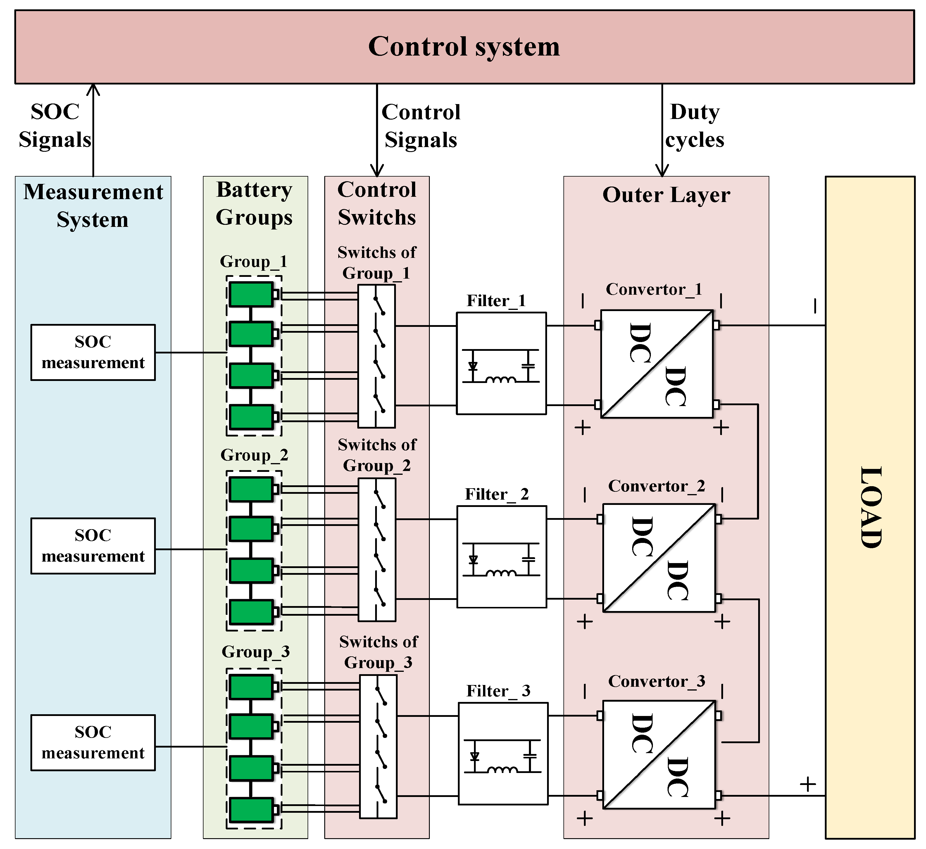
2. Double Layer Equalization Model

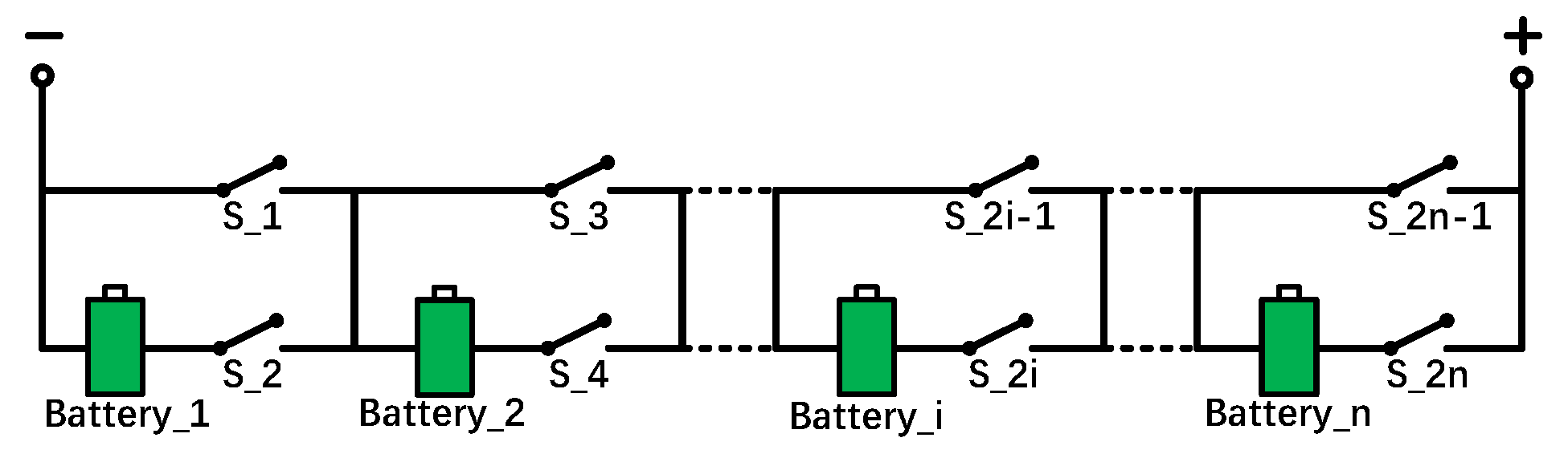
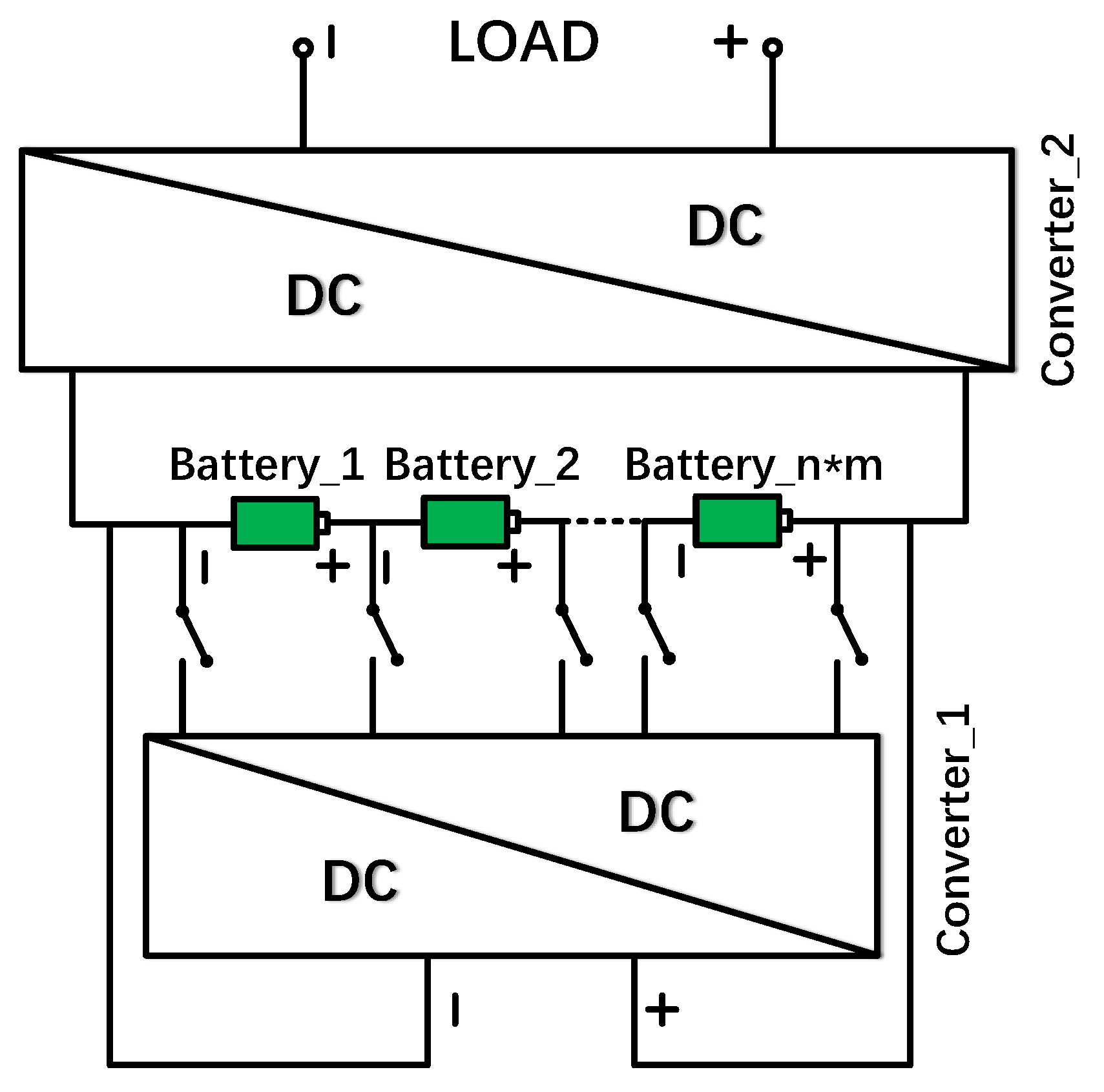
2.1. Inner Layer: Reconfigurable Equalization Topology

As shown in Figure 1, the series reconfigurable balancing group is composed of n lithium-ion battery cells and 2 n MOSFETs. Each cell is fitted with two MOSFETs. By turning on (or off) one of the switches and turning off (or on) the other, the corresponding cell can be connected to the circuit or be isolated.
Accurate SOC estimation is critical to ensure the safe and reliable operation of battery management systems in all applications. Scholars have proposed a variety of effective approaches to estimate the SOC of the battery and diagnose faults in the circuit [25,26,27,28,29]. Since it is not the focus of this research, we used the measuring port of the battery cell block in Simulink to obtain the value of SOC directly.
Assume that in the initial state, S O C 1 is the highest in the group, S O C i is the lowest in the group, and S O C n lies between them, as shown in Figure 2. To simplify the explanation, we use cell 2 to represent the other cells in the group and assume that S O C 2 equals S O C 1 (Actually, the two SOCs do not have to be completely the same. The SOCs can be considered equal if the difference between them is less than   ε 1 ). If each cell has a unique SOC, the system will perform this process several times until the SOCs of all cells are equal.
The equalization process is shown in Figure 3.
(1)
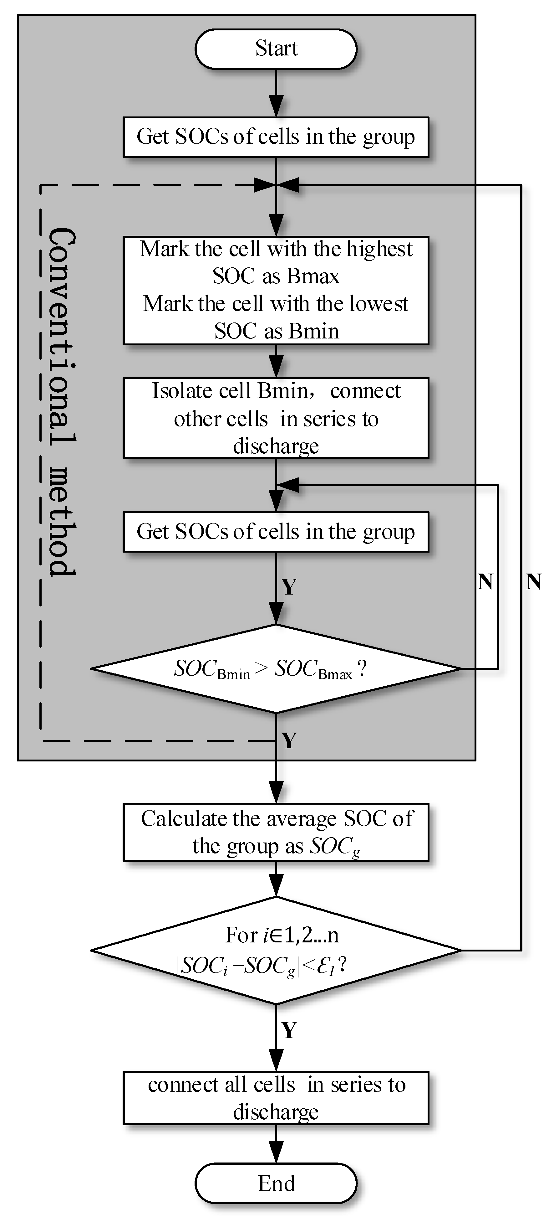
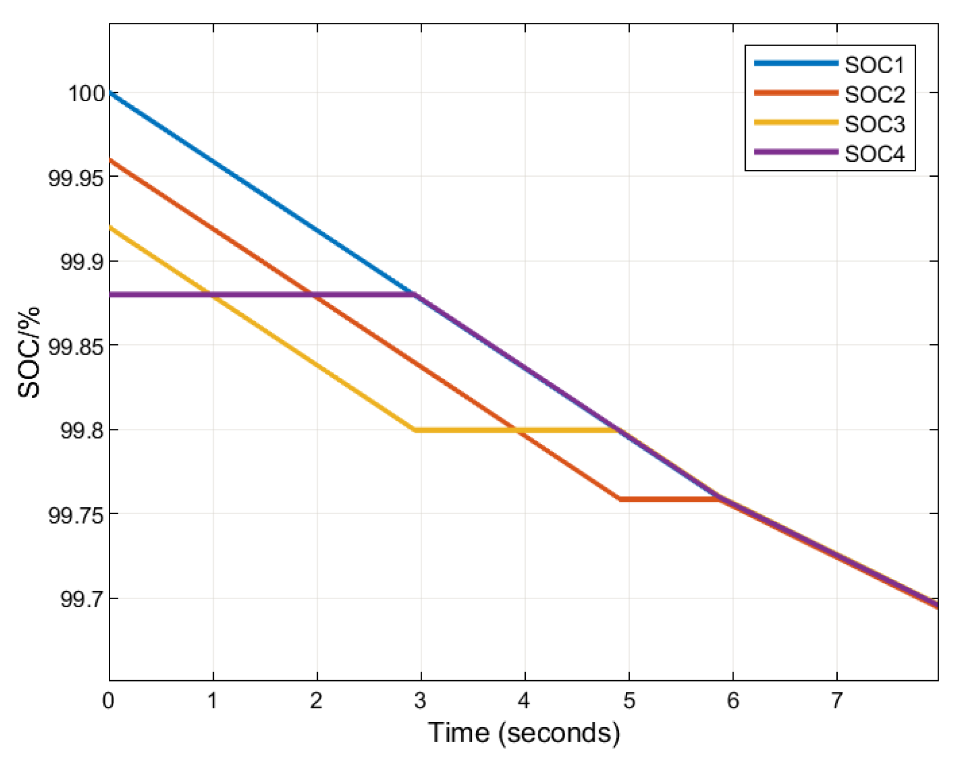
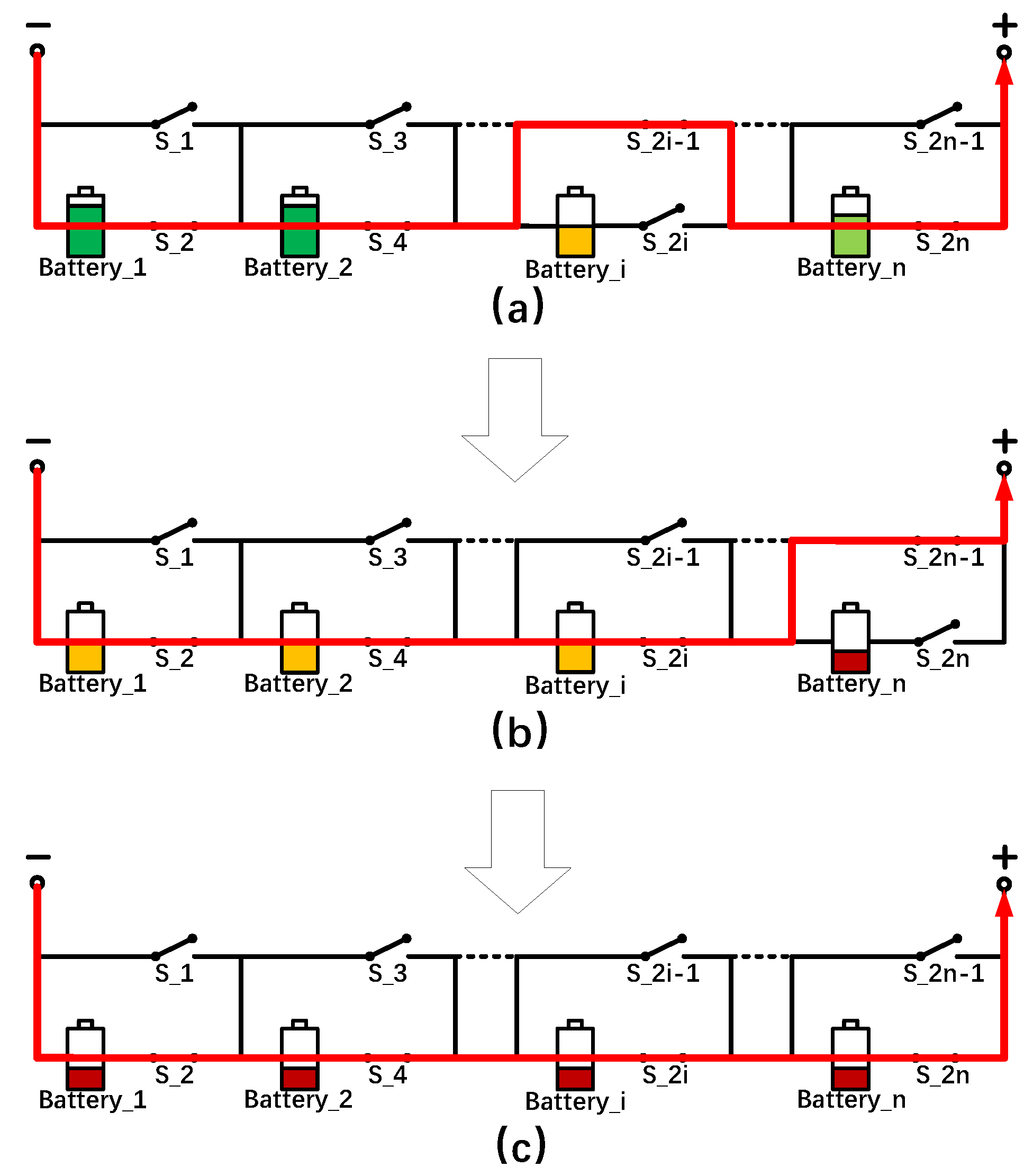
At the beginning of the equalization (Figure 3a), the system collects the SOCs of all the cells in the group. The cell with the lowest SOC (cell i) is isolated (switch on S_2i − 1, switch off S_2i), and the other cells are connected in series to discharge (switch on S_2, S_4…S_2n, switch off S_1, S_3…S_2n − 1).
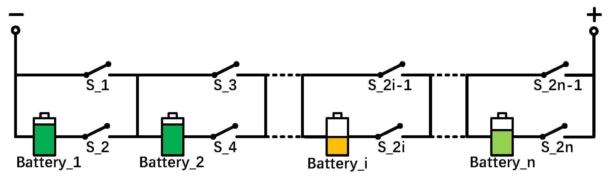
(2)
The series battery group continuously discharges until the SOC of the cell with the highest SOC in step (1) (cell 1) equals the SOC of the cell being isolated (cell i) (Figure 3b). Then the cell being isolated (cell i) is connected to the working part of the group (switch on S_2i, switch off S_2i − 1). Meanwhile, the cell with the lowest SOC at this moment (cell n) is isolated (switch on S_2n − 1, switch off S_2n).
(3)
The series battery group repeats steps (1) and (2) until all the SOCs are equal. (Figure 3c). At this moment, all the cells have similar SOCs, and the process of equalization in this group is over. Then all the cells are connected in series to discharge (switch on S_2n, switch off S_2n − 1).
The cell with the lowest SOC is bypassed, and the rest of the cells are connected in series to discharge during the whole equalization process. All the cells are at work state when the equalization is completed. The working part of the group consists of n 1 cells during equalization while n cells after equalization. When the cells are bypassed, the output voltage of the group gets smaller, and the output current will increase at the same time to ensure constant output power. Ref. [30] has proven that the larger the output current is, the smaller the capacity the battery can discharge. In this study, no more than one cell can be bypassed at the same time to reduce the influence of bypassing the cell on the actual discharge capacity.
Although this series reconfigurable topology can realize the equalization of the battery group, there are also some problems in practical application: firstly, the output voltage of the battery group during the equalization is the sum of n 1 cell voltages.
V g = i n v i v min
The output voltage of the battery group after the equalization is the sum of n cell voltages.
V g = i n v i
Therefore, there will be a voltage rise of v min between before and after equalization.
Secondly, the output voltage of a lithium-ion battery decreases slowly during the discharge process [31], according to the discharge voltage curve of the lithium-ion battery (Figure 4 takes the lithium-ion battery with a rated voltage of 7.2 V, a capacity of 5.4 Ah, and a discharge rate of 0.43C as an example).
The output voltages are 7.732 V at 0.5 h and 7.388 V at 2 h in Figure 4, and the voltage decay exceeds 4%. We can conclude that the reconfigurable topology cannot be used alone because it cannot keep a stable output voltage for the load. Therefore, it is necessary to design an outer equalization layer to achieve balance among the battery groups as well as to maintain the stability of the output voltage.

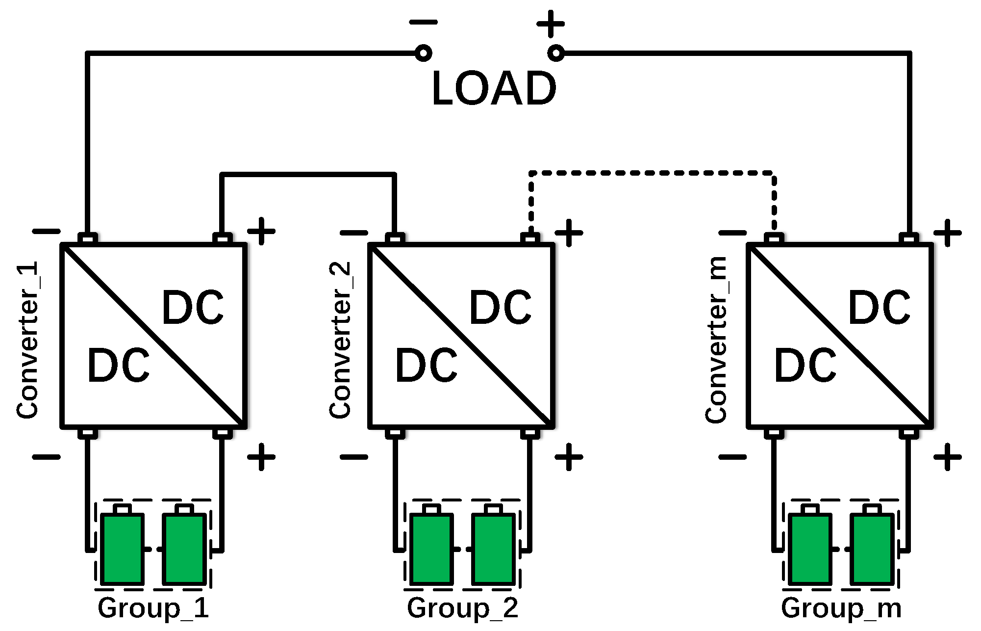
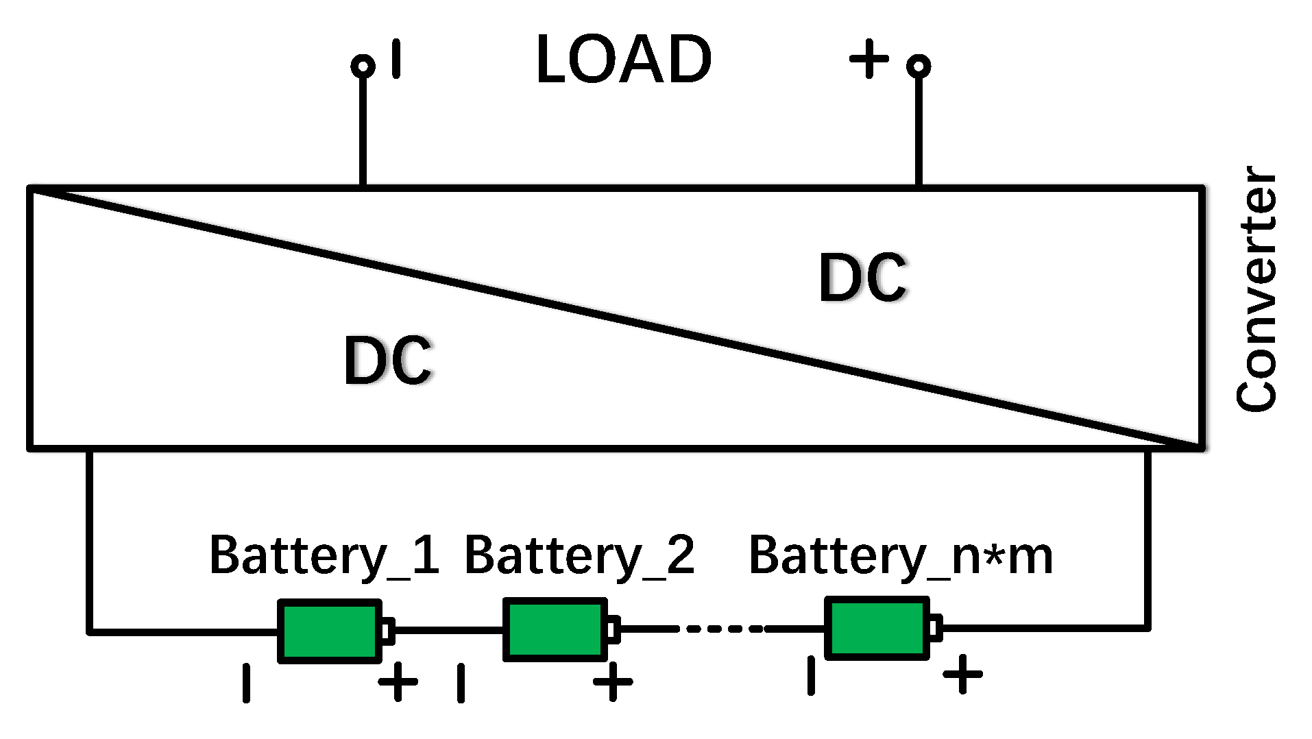
2.2. Outer Layer: Power Distribution through Buck–Boost Converters

As shown in Figure 5, the outer layer equalization topology is composed of m series-connected battery groups connected to m Buck–Boost converters, and the outputs of m converters are connected in series to supply stable power to the load.
There are m converters connected in series with the same output current, so the converter with larger output voltage V c j (j = 1, 2…m) has larger output power. According to the working principle of the Buck–Boost converter, the relationship between the output voltage and the input voltage of the jth converter is given below
V c j = t on t off V g j = t on T t on V g j = α j 1 α j V g j
where t on is the on time of the MOSFET, t off is the off time of the MOSFET and T is the switching period of the MOSFET. α j can be calculated based on (4)
α j = V c j V g j + V c j
The output voltage of the converter can be controlled by adjusting the duty ratio α j of the converter. We arrange the battery groups in descending order of S O C g j (j = 1, 2…m), which is the average SOC of the jth battery group. The converters connected to the battery groups with higher average SOCs are set with higher duty ratios and output higher voltages and powers; the converters connected to the battery groups with lower average SOCs are set with lower duty ratios and output lower voltages and powers. The relationship between the output voltages V out j (j = 1, 2…m) can be expressed as
V c 1 V c 2 V c m
V c 1 + V c 2 + + V c m = V out
k j   is the proportion of the output voltage of the jth converter of the total output voltage.
k j = V c j V out
The relationship between k j   (j = 1, 2…m) can be expressed as
k 1 k 2 k m
k 1 + k 2 + + k m = 1
From (4) and (7), the relationship between k j   and α j can be inferred as follows:
α j = k j V out V g j + k j V out
From (3) and (10), we can control the output voltage and power of the jth converter by adjusting α j by calculating the appropriate k j according to the requirement of balancing speed, V g j , and V out . Until the average SOCs of all groups are equal (The average SOCs do not have to be completely the same. The average SOCs can be considered equal if the difference between any two average SOCs is less than ε 2 ), all battery groups are set to discharge at the same power as (11).
k 1 = k 2 = = k m = 1 m
The equalization of the outer layer is completed.

3. Control Strategy

3.1. Control Strategy of the Inner Layer

The conventional equalization strategy always isolates the battery cell with the lowest SOC from the group. The working part is formed by the remaining n 1 cells connected in series to discharge. When the SOC of the isolated cell is equal to the cell with the highest SOC among the remaining cells, the new cell with the lowest SOC will be isolated, and the original isolated cell will be connected to the working part. The conventional equalization strategy is shown in the shaded area (dotted line) of Figure 6. This control strategy has disadvantages in that the system is always in the circulation of equalization, the cells in the working part are constantly switched, and there is always a cell isolated from the pack, which reduces both the balancing efficiency and the maximum output power of the battery group [32].
In this study, an advanced control strategy is proposed. A monitoring section has been added to check whether the equalization of the inner layer is completed. It is considered that the equalization of the battery group is accomplished if the difference between the SOC of any cell in the group and the average SOC of the group is less than ε 1 . Then all n cells are connected in series to discharge.

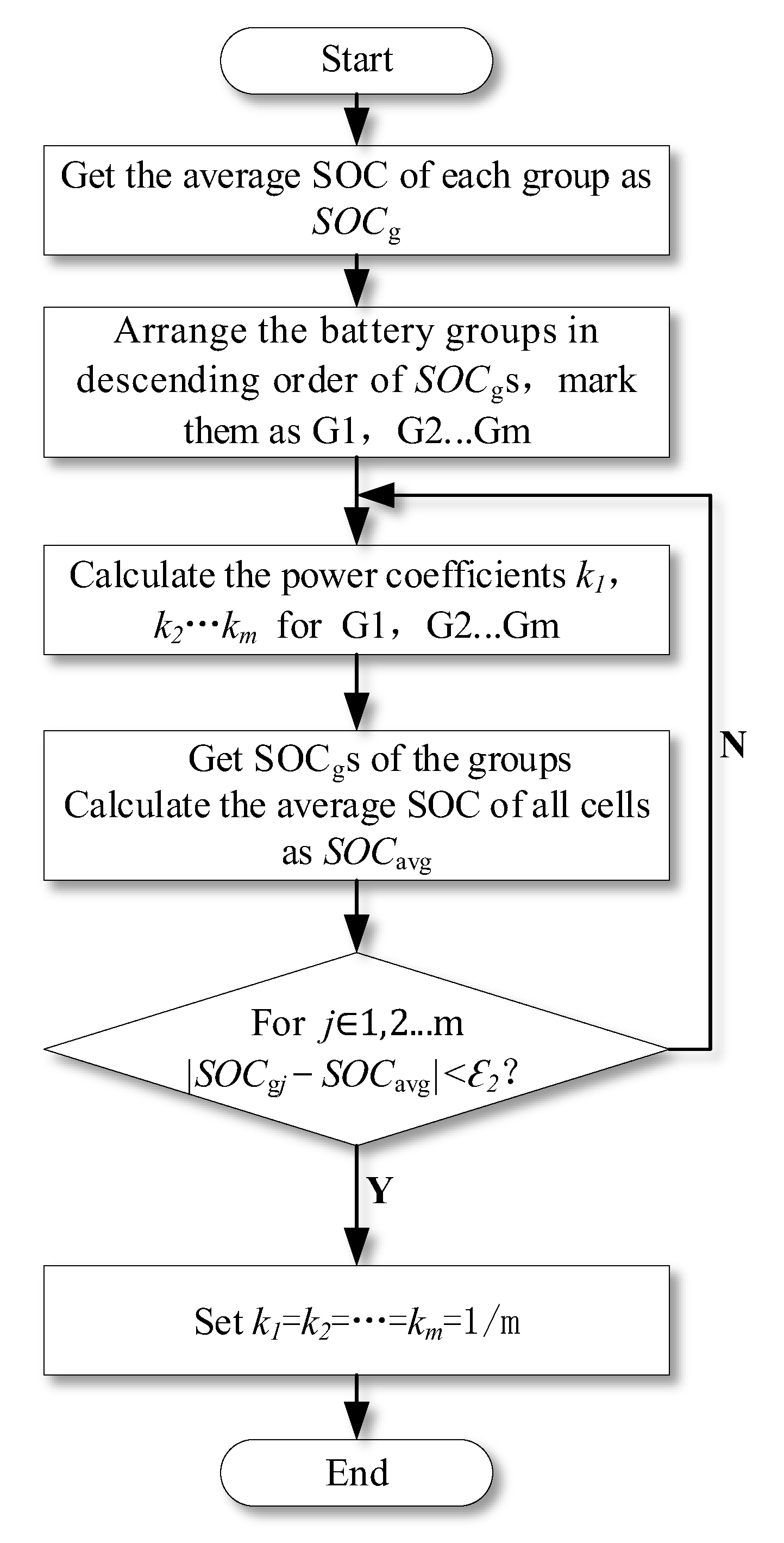
3.2. Control Strategy of the Outer Layer

The control strategy of the outer layer proposed in this paper is shown in Figure 7. We arrange the battery groups in descending order of S O C g j (j = 1, 2…m) as mentioned in Section 2. The power coefficients k j (j = 1, 2…m) are set in descending order as well. S O C avg is the average SOC of all the n × m cells. It is considered that the jth battery group has reached a balance if the difference between S O C g j and S O C avg is less than ε 2 after a period of equalization. After all m battery groups get balanced, the same power coefficient of 1 / m is set for all battery groups, and all battery groups discharge at the same power. The equalization of the system is completed.

4. Calculation and Comparison

In this section, calculations are made to compare the efficiency of the proposed method with the conventional method. Some of the parameters used in the calculations are listed in Table 1 (ignoring the resistance of the lead).

4.1. Efficiency Calculation of the Ideal Working Circuit

Firstly, an ideal series working circuit will be introduced, as shown in Figure 8. It is assumed that the battery cells in the ideal circuit are balanced all the time, and only the power loss caused by the internal resistances of the cells and the efficiency of the converter should be taken into consideration.
P g denotes the output power of the series battery group (the input power of the converter). The relationship between P g and P is
P g = P η
The output voltage of the battery group can be calculated as
V g = n m v
The current flowing through each cell can be calculated as
I g = P g V g = P n m v η
The power loss caused by the internal resistances of the cells is
P r = I g 2 R = ( P n m v η ) 2 n m r = P 2 r n m v 2 η 2
The total power all the battery cells spend is
P all = P g + P r
Thus, the total efficiency of the ideal circuit can be expressed as
η 1 = P P all = 1 1 η + P r n m v 2 η 2

4.2. Efficiency Calculation of the Conventional Equalization Circuit Based on DC/DC Converter

A conventional active equalization circuit using a converter as an energy transfer device is shown in Figure 9. This circuit consists of two DC/DC converters and n × m battery cells connected in series. DC/DC converter 1 equalizes the cells in the pack, while DC/DC converter 2 controls the output voltage to be stable.
The output power, the output voltage of the series battery group, and the current flowing through the cells of the conventional converter equalization circuit can also be expressed as Equations (12)–(14). The power loss caused by the internal resistances of the cells and the MOSFETs of the conventional converter equalization circuit can be calculated as
P eq r = I eq 2 2 r s = ( P eq v ) 2 2 r s
Moreover, the power loss of converter 1 during the equalization is
P cvt = P eq ( 1 η )
The total power all the battery cells spend is
P all = P g + P r + P eq r + P cvt
The total efficiency of the conventional converter equalization circuit can be expressed as
η 2 = P P all = P P η + ( P n m v η ) 2 ( n m r + 2 r s ) + P eq ( 1 η )

4.3. Efficiency Calculation of the Proposed Circuit

The total output power of the series battery groups of the proposed circuit can also be expressed as (12). The output voltage of a single battery group in the proposed circuit during the equalization is
V g = ( n 1 ) v
The current flowing through each cell can be calculated as
I g = P g m V g = P ( n 1 ) m v η
The power loss caused by the internal resistances of the cells and the MOSFETs of the proposed circuit can be calculated as
P r = I g 2 R = P 2 ( n 1 ) r + n r s ( n 1 ) 2 m v 2 η 2
The total power all the battery cells spend is
P all = P g + P r
The total efficiency of the proposed equalization circuit can be expressed as
η 3 = P P all = 1 1 η + P ( n 1 ) r + n r s ( n 1 ) 2 m v 2 η 2

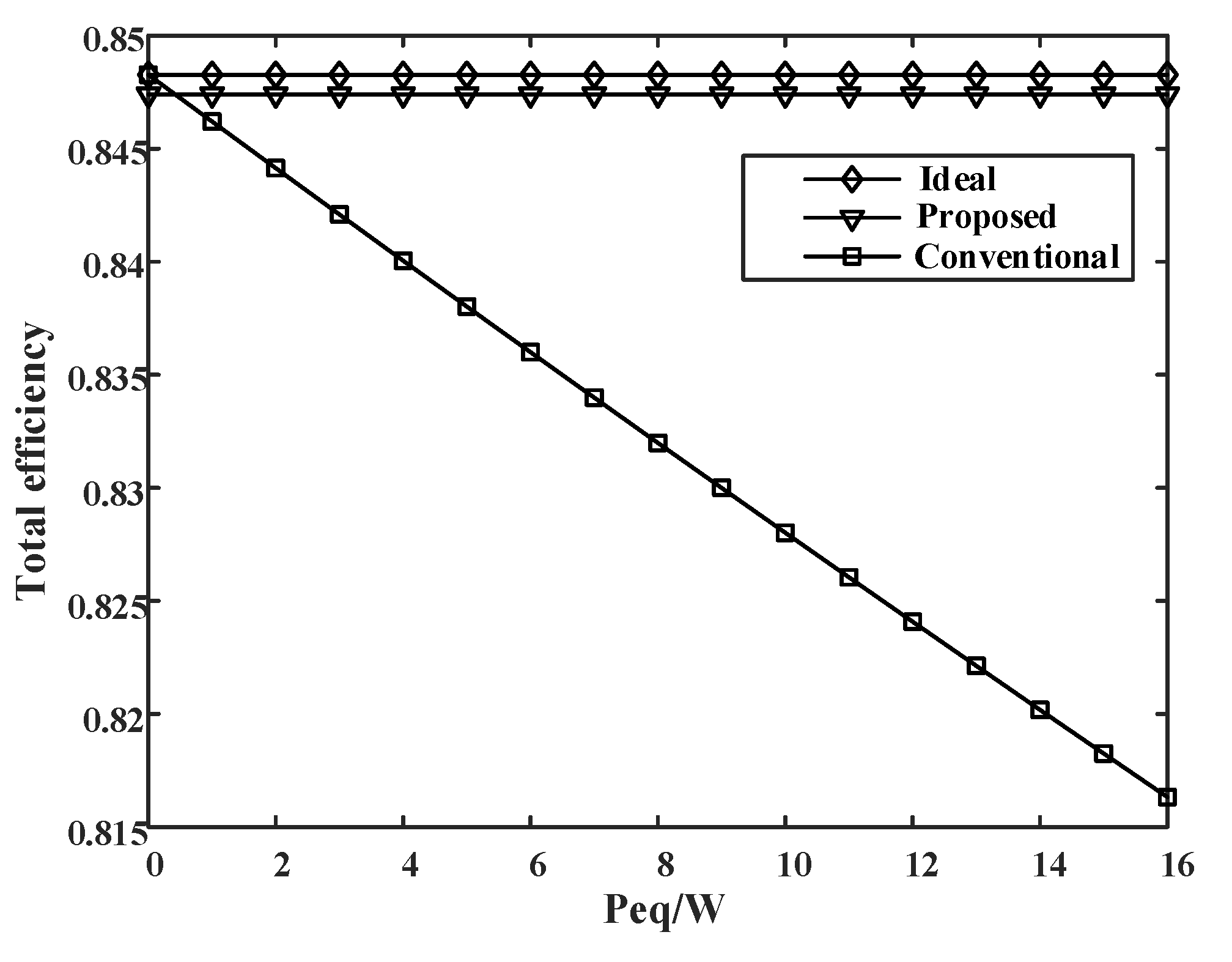
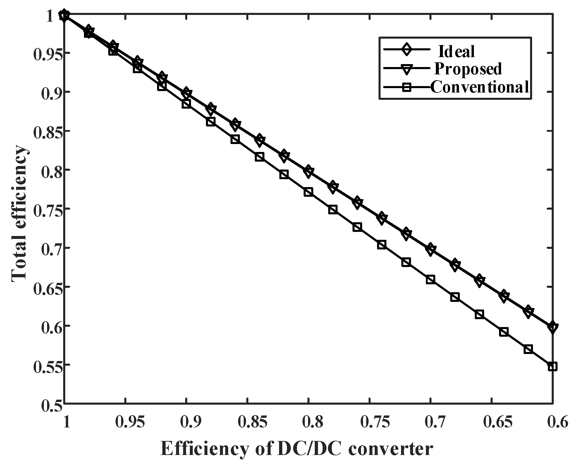
4.4. Comparison of Balancing Efficiency

The efficiencies of the three circuits mentioned above are compared under different P eq and η .
Firstly, assuming that η is constant 85%, the efficiencies of the three circuits versus P eq are shown in Figure 10. The efficiency of the conventional converter equalization circuit is approximate to that of the ideal circuit and higher than the efficiency of the proposed circuit when the equalization power P eq is close to zero. In this situation, the proposed circuit performs worse than the conventional converter circuit because of the extra energy loss caused by MOSFETs. However, the efficiency of the conventional converter circuit decreases straightly with the increase of P eq , while the other two circuits maintain the same efficiency. The proposed circuit outperforms the conventional converter circuit when P eq is larger than 0.5 W in this case. Compared to the conventional converter circuit, the proposed circuit improves the efficiency more significantly when the imbalance gets bigger.
Assuming that P eq is constant 10 W, the efficiencies of the three circuits versus η are shown in Figure 11. The efficiencies of the three circuits are close to 100% when η is close to 100%. The total efficiency of the three circuits all decrease with the decrease of η . The efficiency of the proposed circuit is always close to that of the ideal circuit, but the efficiency of the conventional converter circuit decreases faster than those of the other two circuits. Compared to the conventional converter circuit, the smaller η is, the greater the efficiency improvement the proposed circuit makes.

5. Simulation Results and Discussion

The simulation of a 12 battery cell circuit built on the Matlab/Simulink platform was carried out to validate the feasibility of the proposed double-layer reconfigurable equalization method, as shown in Figure 12. There were three battery groups connected to three Buck–Boost converters, respectively, to form the outer layer. In the inner layer, each battery group consisted of four lithium-ion battery cells connected in series. The three converters in the outer layer were connected in series to supply power to the load which was set to be 50 Ω.
Each lithium-ion battery cell was set to have a rated voltage of 7.2 V and a rated capacity of 5.4 Ah. In the initial state, the SOCs of cell 1 to cell 12 are shown in Table 2. The expected load voltage was set to 150 V.

5.1. Simulation Results of the Inner Layer

The permissible SOC error limit in the battery group, ε 1 , was set to 0.001%. Battery group 1 consisted of cell 1, cell 2, cell 3, and cell 4. The initial SOCs of the cells were 100%, 99.96%, 99.92%, and 99.88%. The equalization process of the inner layer is shown in Figure 13.
Cell 1, cell 2, and cell 3 had higher SOCs and discharged first, while cell 4, with the lowest SOC, was isolated at the beginning of equalization. Cell 4 got balanced and was set to discharge at 2.92 s (the time the difference between S O C 4 and S O C 1 is no more than ε 1 ); at the same time, cell 3 with the lowest SOC got isolated. The equalization processes of cell 3 and cell 2 were similar to that of cell 4. Cell 3 and cell 2 reached balance at 4.90 s and 5.87 s. The inner layer equalization of battery group 1 was completed, and all the cells were connected in series to discharge at 5.87 s. There were three cells discharging in the group before 5.87 s but four cells after 5.87 s. The output power of each cell was reduced because the output power of the battery group was constant, but the number of working cells increased. Therefore, the decline rate of the SOC curve slowed down after 5.87 s.

5.2. Simulation Results of the Outer Layer

The permissible SOC error limit between the battery groups, ε 2 , was set to 0.002%. The average SOCs of battery groups 1, 2, and 3 were 99.94%, 99.78%, and 99.62% in the initial state. In this case, we have three battery groups, so we should set k 1 , k 2 , and k 3 according to Equation (27) to make sure the three battery groups get balanced at the same time.
k 1 k 2 k 2 k 3 = S O C g 1 S O C g 2 S O C g 2 S O C g 3
The three battery groups discharge at different powers according to k 1 , k 2 , and k 3 . The equalization speed of the outer layer depends on the ratio of k 1 and k 3 . The equalization process of the outer layer is shown in Figure 14.
The power coefficients k 1 , k 2 , and k 3 were calculated and set to be 7/15, 5/15, and 3/15. The differences between any two average SOCs of the three battery groups reached less than 0.002% at 18.1 s. At that moment, the equalization of the outer layer was finished. k 1 , k 2 , and k 3 were reset to 1/3 so that all battery groups would discharge at the same power.

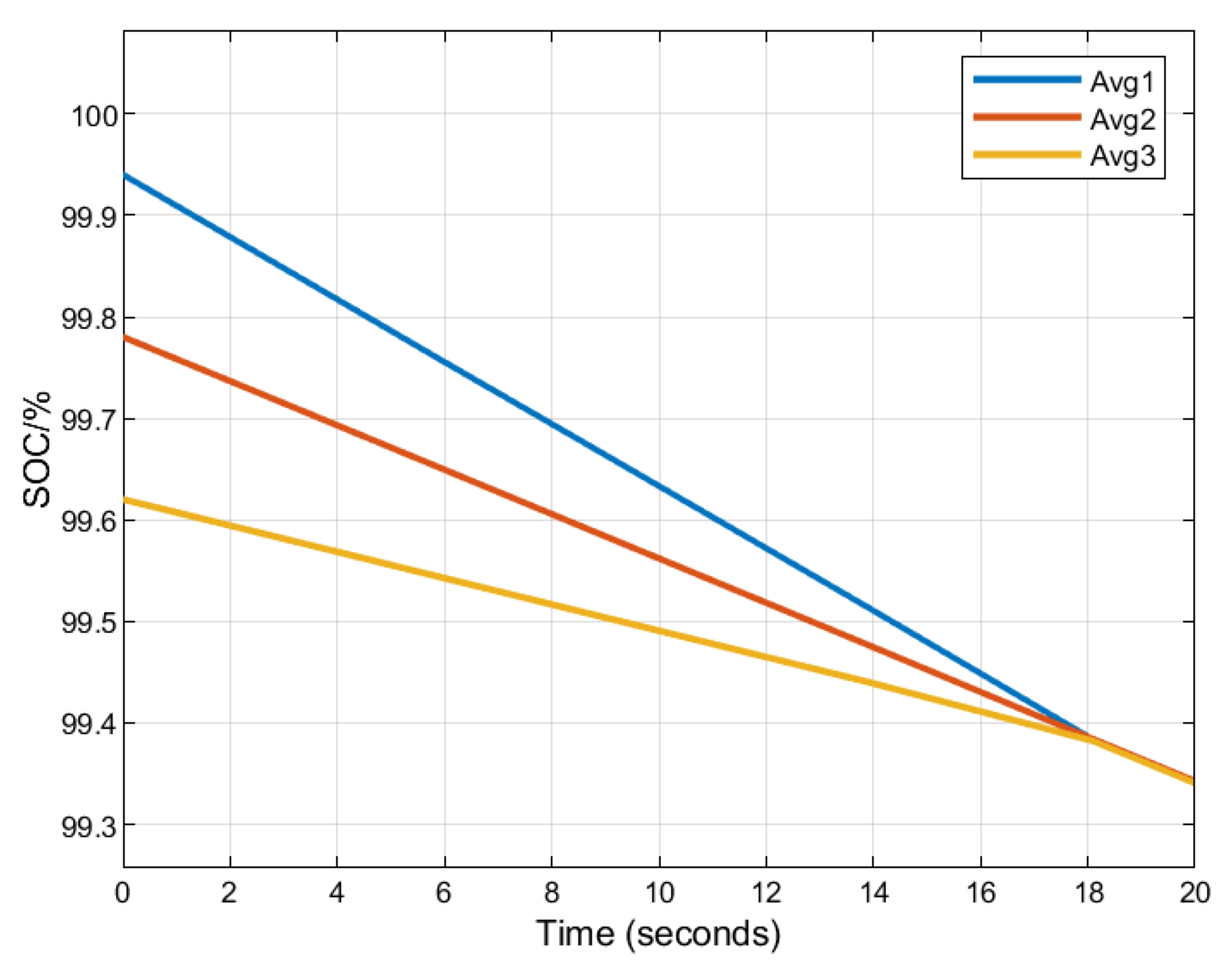
5.3. Simulation Results of the Battery Pack

Each battery group in the outer layer outputs different power due to the different power coefficients k. When the imbalance degrees of the groups are the same, which means the groups have the same amount of electricity to balance, the higher the output power is, the faster the battery group accomplishes its equalization. The equalization process of the battery pack is shown in Figure 15.
Battery group 1, with the highest output power, got balanced at 5.87 s first. Battery group 2, with lower output power, got balanced at 8.28 s. Battery group 3, with the lowest output power, got balanced at 13.96 s. All battery groups in the inner layer were balanced, and all cells were connected to the circuit at 13.96 s. The system finished its equalization, and all the groups began to discharge at the same power at 18.1 s.

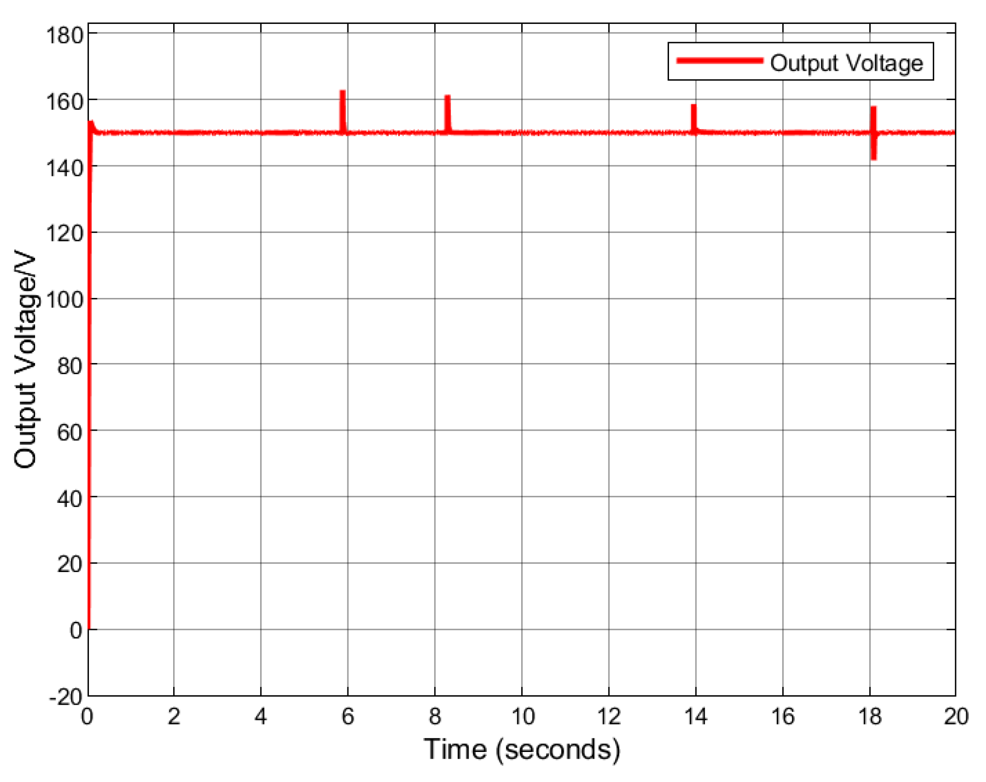
5.4. Simulation Results of the Output Voltage

Each battery group was connected to a Buck–Boost converter, and the outputs of the converters were connected in series. The output voltages of the converters are shown in Figure 16. The output voltages of the three converters became stable after a rise of about 0.2 s. The calculated steady-state voltages of converters 1, 2, and 3 are 70 V, 50 V, and 30 V according to Equation (7), and the simulation results are consistent with the calculation results.
The total output voltage of the battery pack was generally stable at 150 V, as shown in Figure 17. The output voltage had pulse distortion at 5.87 s, 8.28 s, and 13.96 s (all of which returned stabilization within 0.1 s), as shown in Figure 16 and Figure 17. The reason is that the number of working cells in the group increased from three to four when the equalization in the battery group was completed. The input voltage of the converter instantly increased by 1 cell voltage. However, the input current and the output current of the converter could not suddenly change due to the inductance in the converter. The output power of the converter would rise briefly and then stabilize. The number of battery groups will be far greater than three, and the number of battery cells in each group will be far greater than four when the proposed method is used in practical energy storage systems. So the voltage distortion caused by the switch of one battery cell will be small enough to be ignored. There are also some ways to eliminate the distortion. We can eliminate the voltage distortion and ensure the stable output voltage of the system by connecting the extra cells to the groups during equalization and isolating them after equalization. The same result can be achieved by using a regulated power supply.

6. Conclusions

In this paper, a double-layer equalization method combining the reconfigurable topology with the converter active equalization method is proposed. The equalization strategies of the inner and outer layers are discussed in detail, and the feasibility of the proposed method is validated by simulation. The main concluding remarks can be made below:
(1)
The inner layer proposed in this paper realizes balance among cells in the same group through the reconfigurable topology. Compared with the conventional active equalization method, the proposed method uses fewer components, has lower cost, higher efficiency, and simpler control complexity. Moreover, the equalization process goes on equally well regardless of the positions the cells needed to be balanced in the group.
(2)
The method of connecting the outputs of converters in series is used in the outer layer. The proposed outer layer can realize the balance among battery groups and keep the output voltage and power of the system stable at the same time. It solves the problem that using the reconfigurable topology alone cannot stabilize or adjust the output voltage.
(3)
The efficiency of the proposed equalization method was calculated and compared with the conventional converter active equalization method. The results showed that the proposed method can improve the balancing efficiency, and the higher the unbalance of the battery system is, the more significant the improvement is. The proposed method is suitable for scenarios like retired battery energy storage systems which have high power, large capacity, and high requirements for balancing efficiency and robustness.

Author Contributions

Conceptualization, Y.L.; methodology, P.Y.; validation, Y.L., J.C. and P.Y. All authors have read and agreed to the published version of the manuscript.

Funding

This research is supported by the National Key Research and Development Program of China (2021YFB1600202) and the Key Research and Development Projects of Shaanxi Province, China (2021KW-13).

Institutional Review Board Statement

Not applicable.

Informed Consent Statement

Not applicable.

Data Availability Statement

Not applicable.

Conflicts of Interest

The authors declare no conflict of interest.

References

  1. Li, J.; Li, Y.; Lyu, C.; Zhao, W.; Zhou, J. Key Technology and Research Status of Cascaded Utilization in Decommissioned Power Battery. Autom. Electr. Power Syst. 2020, 44, 172–183. [Google Scholar]
  2. Wang, S. Research on Sorting and Grouping for Second-Use of Retired Battery Modules. Ph.D. Thesis, North China Electric Power University, Beijing, China, 2021. [Google Scholar]
  3. Dai, S.; Zhang, F.; Zhao, X. Series-connected battery equalization system: A systematic review on variables, topologies, and modular methods. Int. J. Energy Res. 2021, 45, 19709–19728. [Google Scholar] [CrossRef]
  4. Zhang, Y.; Huang, M.M.; Wu, T.Z.; Ji, F. Reconfigurable equilibrium circuit with additional power supply. Int. J. Low-Carbon Technol. 2020, 15, 106–111. [Google Scholar] [CrossRef] [Green Version]
  5. Javier, G.L.; Enrique, R.C.; Isabel, M.M.; Miguel, A.G.M. Battery equalization active methods. J. Power Sources 2014, 246, 934–949. [Google Scholar]
  6. Jiang, Y.; Jiang, J.C.; Zhang, C.P.; Zhang, W.G.; Gao, Y.; Guo, Q.P. Recognition of battery aging variations for LiFePO4 batteries in 2nd use applications combining incremental capacity analysis and statistical approaches. J. Power Sources 2017, 360, 180–188. [Google Scholar] [CrossRef]
  7. Zhou, H.; Wu, H.; Han, X.B.; Zheng, Y.J.; Yan, L.Q.; Lv, T.L.; Xie, J.Y. An expeditious and simple scheme for measuring self-discharge rate of lithium batteries. Int. J. Energy Res. 2022, 46, 15948–15960. [Google Scholar] [CrossRef]
  8. Zhou, L.; Zheng, Y.J.; Ouyang, M.G.; Lu, L.G. A study on parameter variation effects on battery packs for electric vehicles. J. Power Sources 2017, 364, 242–252. [Google Scholar] [CrossRef]
  9. Bandhauer, T.M.; Garimella, S.; Fuller, T.F. A Critical Review of Thermal Issues in Lithium-Ion Batteries. J. Electrochem. Soc. 2011, 158, R1–R25. [Google Scholar] [CrossRef]
  10. Hua, Y.; Zhou, S.D.; Cui, H.G.; Liu, X.H.; Zhang, C.; Xu, X.W.; Ling, H.P.; Yang, S.C. A comprehensive review on inconsistency and equalization technology of lithium-ion battery for electric vehicles. Int. J. Energy Res. 2020, 44, 11059–11087. [Google Scholar] [CrossRef]
  11. Seong, W.M.; Park, K.Y.; Lee, M.H.; Moon, S.; Oh, K.; Park, H.; Lee, S.; Kang, K. Abnormal self-discharge in lithium-ion batteries. Energy Environ. Sci. 2018, 11, 970–978. [Google Scholar] [CrossRef]
  12. McCurlie, L.; Preindl, M.; Emadi, A. Fast Model Predictive Control for Redistributive Lithium-Ion Battery Balancing. IEEE Trans. Ind. Electron. 2017, 64, 1350–1357. [Google Scholar] [CrossRef]
  13. Baronti, F.; Roncella, R.; Saletti, R. Performance comparison of active balancing techniques for lithium-ion batteries. J. Power Sources 2014, 267, 603–609. [Google Scholar] [CrossRef]
  14. Cai, M.; Zhang, E.; Lin, J.; Wang, K.; Jiang, K.; Zhou, M. Review on Balancing Topology of Lithium-ion Battery Pack. Proc. CSEE 2021, 41, 5294–5310. [Google Scholar]
  15. Hua, Y.; Zhou, S.; He, R.; Cui, H.; Yang, S. Review on Lithium-ion Battery Equilibrium Technology Applied for EVs. J. Mech. Eng. 2019, 55, 73–84. [Google Scholar]
  16. Kim, M.Y.; Kim, C.H.; Kim, J.H.; Moon, G.W. A Chain Structure of Switched Capacitor for Improved Cell Balancing Speed of Lithium-Ion Batteries. IEEE Trans. Ind. Electron. 2014, 61, 3989–3999. [Google Scholar] [CrossRef]
  17. Li, X.L.; Xu, S.G.; Xu, J.P.; Liu, Q.Y. Single-inductor bidirectional battery equalizer. Electr. Mach. Control 2019, 23, 90–97. [Google Scholar]
  18. Shang, Y.L.; Zhang, C.H.; Cui, N.X.; Mi, C.C. A Delta-Structured Switched-Capacitor Equalizer for Series-Connected Battery Strings. IEEE Trans. Power Electron. 2019, 34, 452–461. [Google Scholar]
  19. Shang, Y.; Xia, B.; Zhang, C.; Cui, N.; Yang, J.; Mi, C.C. An Automatic Equalizer Based on Forward–Flyback Converter for Series-Connected Battery Strings. IEEE Trans. Ind. Electron. 2017, 64, 5380–5391. [Google Scholar] [CrossRef]
  20. Yuanliang, F.; Yule, W.; Gang, Z.; Han, W.; Jianye, H. A novel circuit for reducing equalizing currents in reconfigurable battery packs. In Proceedings of the 2020 8th International Conference on Power Electronics Systems and Applications (PESA), Hong Kong, China, 7–10 December 2020. [Google Scholar]
  21. Ci, S.; Lin, N.; Wu, D.L. Reconfigurable Battery Techniques and Systems: A Survey. IEEE Access 2016, 4, 1175–1189. [Google Scholar] [CrossRef]
  22. Xiaoqian, W.; Bin, D.; Yunlong, S.; Yinghui, X.; Keke, Y.; Chenghui, Z. Fast Equalization for Lithium Ion Battery Packs Based on Reconfigurable Battery Structure. In Proceedings of the 2020 IEEE/IAS Industrial and Commercial Power System Asia (I&CPS Asia), Weihai, China, 13–16 July 2020; pp. 1149–1154. [Google Scholar]
  23. Rahman, M.A.; de Craemer, K.; Buscher, J.; Driesen, J.; Coenen, P.; Mol, C. Comparative Analysis of Reconfiguration Assisted Management of Battery Storage Systems. In Proceedings of the 45th Annual Conference of the IEEE Industrial Electronics Society, Lisbon, Portugal, 14–17 October 2019. [Google Scholar]
  24. Muhammad, S.; Rafique, M.U.; Li, S.; Shao, Z.L.; Wang, Q.X.; Liu, X. Reconfigurable Battery Systems: A Survey on Hardware Architecture and Research Challenges. ACM Transact. Des. Automat. Electron. Syst. 2019, 24, 27. [Google Scholar] [CrossRef]
  25. Meng, J.W.; Boukhnifer, M.; Diallo, D.; Wang, T.Z. Short-Circuit Fault Diagnosis and State Estimation for Li-ion Battery using Weighting Function Self-Regulating Observer. In Proceedings of the Prognostics and System Health Management Conference, Besancon, France, 4–7 May 2020. [Google Scholar]
  26. Xiong, R.; Sun, F.C.; Chen, Z.; He, H.W. A data-driven multi-scale extended Kalman filtering based parameter and state estimation approach of lithium-ion polymer battery in electric vehicles. Appl. Energy 2014, 113, 463–476. [Google Scholar] [CrossRef]
  27. Yang, F.F.; Li, W.H.; Li, C.; Miao, Q. State-of-charge estimation of lithium-ion batteries based on gated recurrent neural network. Energy 2019, 175, 66–75. [Google Scholar] [CrossRef]
  28. Wei, Z.B.; Zou, C.F.; Leng, F.; Soong, B.H.; Tseng, K.J. Online Model Identification and State-of-Charge Estimate for Lithium-Ion Battery With a Recursive Total Least Squares-Based Observer. IEEE Trans. Ind. Electron. 2018, 65, 1336–1346. [Google Scholar] [CrossRef]
  29. Feng, F.; Teng, S.L.; Liu, K.L.; Xie, J.L.; Xie, Y.; Liu, B.; Li, K.X. Co-estimation of lithium-ion battery state of charge and state of temperature based on a hybrid electrochemical-thermal-neural-network model. J. Power Sources 2020, 455, 227935. [Google Scholar] [CrossRef]
  30. He, L.; Kim, E.; Shin, K.G. A Case Study on Improving Capacity Delivery of Battery Packs via Reconfiguration. ACM Trans. Cyber-Phys. Syst. 2017, 1, 23. [Google Scholar] [CrossRef]
  31. Ji, F.; Liao, L.; Wu, T.Z.; Chang, C.; Wang, M.N. Self-reconfiguration batteries with stable voltage during the full cycle without the DC-DC converter. J. Energy Storage 2020, 28, 9. [Google Scholar] [CrossRef]
  32. Wu, T.Z.; Huang, Z.Y.; Lu, C.D. Research on two-level equalization method based on reconfigurable circuit. Chin. J. Power Sources 2020, 44, 1671–1674. [Google Scholar]
Figure 1. Reconfigurable equalization topology.
Applsci 13 01154 g001
Figure 2. Initial state of SOC.
Applsci 13 01154 g002
Figure 3. Equalization process: (a) At the beginning of the equalization, battery i is isolated; (b) In the middle of the equalization, battery n is isolated; (c) End of equalization.
Applsci 13 01154 g003
Figure 4. Discharge voltage curve.
Applsci 13 01154 g004
Figure 5. Topology of outer layer.
Applsci 13 01154 g005
Figure 6. Control strategy of conventional method (shaded area, dotted line)/control strategy of the proposed inner layer.
Applsci 13 01154 g006
Figure 7. Control strategy of the proposed outer layer.
Applsci 13 01154 g007
Figure 8. Ideal circuit.
Applsci 13 01154 g008
Figure 9. Conventional converter equalization circuit.
Applsci 13 01154 g009
Figure 10. The total efficiency versus the equalization power P eq .
Applsci 13 01154 g010
Figure 11. The total efficiency versus the efficiency of converter η .
Applsci 13 01154 g011
Figure 12. Schematic diagram of proposed method.
Applsci 13 01154 g012
Figure 13. Equalization process of battery group 1.
Applsci 13 01154 g013
Figure 14. Equalization process of outer layer.
Applsci 13 01154 g014
Figure 15. Equalization process of battery pack.
Applsci 13 01154 g015
Figure 16. Output voltage of each converter.
Applsci 13 01154 g016
Figure 17. Output voltage of the battery pack.
Applsci 13 01154 g017
Table 1. The parameters of equalization efficiency calculations.
ParametersValue
number of battery cells n × m 4 × 3
internal resistance of a battery cell r /Ω0.01
internal resistance of a MOSFET r s /Ω0.001
output voltage of a battery cell v /V7.2
load voltage V out /V72
load current I out /A1
load power P /W72
equalization power P eq /W
efficiency of DC/DC converter η /%
Table 2. The SOCs of battery cells.
Cell Number123456789101112
SOC (%)10099.9699.9299.8899.8499.8099.7699.7299.6899.6499.6099.56
Disclaimer/Publisher’s Note: The statements, opinions and data contained in all publications are solely those of the individual author(s) and contributor(s) and not of MDPI and/or the editor(s). MDPI and/or the editor(s) disclaim responsibility for any injury to people or property resulting from any ideas, methods, instructions or products referred to in the content.

