
Asymptotic Theory of Flapping Wing Propulsion in Extreme Ground Effect

Department of Applied Mathematics and Mathematical Modeling, Saint Petersburg State Marine Technical University, Saint Petersburg 190121, Russia
Appl. Sci. 2023, 13(2), 690; https://doi.org/10.3390/app13020690
Submission received: 20 November 2022
/
Revised: 29 December 2022
/
Accepted: 2 January 2023
/
Published: 4 January 2023
Abstract
:This study, dedicated to flapping wing propulsion in immediate proximity to a wall or between closely spaced flat walls, makes use of the method of matched asymptotic expansions. Its purpose is to create a simplified parametric model of such a propulsion system based on a single major assumption: immediate closeness of oscillating wing to a solid wall. In the case of a rectangular finite-aspect ratio wing, analytical expressions have been obtained for the coefficients of instantaneous and period-averaged thrust force as well as for the efficiency of the propulsor as a function of distance from the wall, Strouhal number and wing aspect ratio for selected cases of heaving, pitching and combined oscillations. It is shown that for some oscillation modes closeness to the ground results in increases in thrust and efficiency, and that optimally combined (considering ratio of the amplitudes and phase shift of contributing motions) heave–pitch oscillations allow to maximize thrust or efficiency of the flapping-wing propulsor. Increase in aspect ratio and decrease in Strouhal number (relative frequency of oscillations) in the case of heaving invariably brings about the increase in the ideal efficiency. An example is provided of a non-planar extreme ground effect application considering oscillations of a ring-wing embracing circular cylinder. A rule is derived for recalculation of the characteristics of the flapping-wing propulsor near a flat wall onto the characteristics of the same wing operating in a narrow canal between parallel walls. This rule can also be applied to evaluate propulsive properties of a ring-wing oscillating between co-axial cylindric surfaces.
1. Introduction
It is well-known that for an appropriately designed wing the presence of an underlying solid boundary enhances its lifting properties and the corresponding phenomenon is known as ground effect. It turns out that a wing oscillating near a wall similarly manifests enhancement of its propulsive characteristics, such as thrust and efficiency, as compared to an unbounded fluid case. Therewith, decrease in relative distance to the wall results in further improvement of the propulsion. An investigation of this propulsion ground effect from the viewpoint of behavior of thrust and efficiency can be carried out with the use of an asymptotic approach, directly accounting for the smallness of relative average distance from the wall. Developed therefrom is an asymptotic theory of a flapping wing in immediate proximity to the ground, leading to analytical results even for a wing of the finite aspect ratio. The proposed mathematical model enables analysis of the efficiency of different modes of operation. It can also be used as an instrument of control of results obtained in this limiting case computationally.
The paper includes: a short review of relevant publications; mathematical formulation of the flow problem for oscillations of a flat wing based on the concept of extreme ground effect; derivations of general expressions for lift, moment and thrust coefficients as well as for propulsive efficiency for separate motions and combination of motions; an illustration of nonplanar unsteady ground effect; discussion of the case of a wing oscillating in a narrow canal between parallel walls and conclusions. The purpose of this work consists in using substantial simplification of the relevant mathematics which opens an interesting and practical parametric space for investigation of flapping wing propulsion close to solid boundaries with visible extension to elastic propulsion systems of hydro-bionic type.
Propulsive characteristics of oscillating wing out of ground effect have been investigated in the works of Theodorsen [1], Nekrasov [2], Sedov [3] and Gorelov [4]. Rozhdestvensky and Ryzhov [5] provided one of the first reviews of research and development of flapping wing propulsors and some representative vehicles equipped with them. In particular, they analyzed natural bionic propulsors of insects, flying warm-blooded vertebrates, also touching upon fish and cetaceans. The authors discussed an engineering classification of propulsive systems with flapping wing elements and some 2D and 3D mathematical models thereof comprising effects of the flow boundaries, unsteadiness and optimal modes of operation. Examples of vehicles making use of flapping wings included: a cutter on underwater flapping and lifting wings developed at Central Aerohydrodynamic Institute named after Zhukovsky in the 1970s, see Grebeshov and Sagoyan [6] (These ideas have been further implemented by designers of pumping hydrofoil and O-foil); a human-powered submarine “Afalina” of Saint Petersburg State Marine Technical University (1992), a 200-ton Russian fishing vessel with a spring-loaded bow wing, see Nikolaev, Savitskiy and Senkin [7]; and MIT laboratory robot “Robotuna”, see Barrett, Grosenbaugh and Triantafyllou [8].
In Rozhdestvensky [9], a simplified mathematical model of a wave glider (WG) was introduced leading to a mass-spring type equation of forced motions for the WG upper displacement unit with account of the inertial and damping influence of the winged lower module. The motions thus found were input into Theodorsen flapping foil theory to determine the thrust of the winged module propelling the WG. The speed of the wave glider was then estimated by equating the thrust available for a given length of the oncoming wave to the drag of the WG, the latter including viscous drag of the glider elements and wave drag of the upper module. Wu et al. [10] published a review on fluid dynamics of flapping foils, providing a summary of both experimental and numerical investigations of flapping foils which comprises effects of relevant parameters, such as Reynolds and Strouhal number, amplitudes of oscillations, three-dimensionality, wake structures and energy harvesting efficiency. Based on statistics of publishing activity in the field, the review states that starting from 2000, the number of papers on flapping foils shows an unprecedented growth. Widely discussed in recent years is a possibility to use flapping wings for ship propulsion and wave energy extraction which is exemplified by the above-mentioned wave gliders (WG)—a two module marine robots converting wave induced motions of the upper displacement hull into thrust of winged lower module resulting in forward motion of the vehicle. Quite a number of studies have been dedicated to elastic foils which can help to considerably increase both thrust and propulsion efficiency of flapping foils. It was also discussed that the efficient use of flapping foils implies optimal superposition of heaving and pitching oscillations of the same frequency albeit shifted in phase. The authors conclude that prevailing are the studies of two-dimensional flapping wing flows whereas 3D case is not yet sufficiently covered. Also underlined are prospects of using multiple foils for thrust generation and power extraction. Rozhdestvensky and Zin Min Htet [11] developed a mathematical model of a ship with energy-saving wings fixed on the ship in the plane of the keel at the extremities. The equations of ship motions comprise coupled heaving and pitching motions, and take into account the inertial and damping effects of the wings. The resulting motions of the wings then allow to calculate additional thrust due to the action of waves. Based on the results obtained both for regular and irregular waves the authors state that use of the wings leads to a noticeable moderation of ship motions, a decrease in the additional wave resistance and, eventually, to a reduction in the energy efficiency design index (EEDI), i.e., lowering of carbon dioxide emissions. The subject of using flapping wings for ship propulsion was also studied by Belibassakis and Politis [12] and Belibassakis and Filippas [13]. Zhu et al. [14] analyzed pressure distributions on a flapping wing near a wall with account of the influence of the time-averaged ground clearance, Reynolds number, effective angle of attack and oscillation frequency upon power extraction efficiency. They underlined that the impact of the ground wall on the power extraction efficiency of the foil becomes increasingly obvious when the oscillation frequency and the angle of attack are increased simultaneously.
Numerical and experimental investigation of flapping wing propulsion in ground effect was undertaken in Jones, Castro, Mahmoud and Platzer, [15]. Flying in ground effect was shown to have substantial performance advantages in thrust and efficiency. The authors used bi-plane configuration and employed high-aspect ratio experimental model with direct measurement of thrust. Numerically they used 2D unsteady inviscid flow model with deforming wake and 2D incompressible Navier–Stokes solver. Zhu, Zhang and Huang [16] noted that flapping wing devices have attracted considerable attention as a new means of power extraction. Applying transient numerical calculations based on the dynamic mesh technique, the authors explored the influence of the leading edge, trailing edge and that of overall circular arc airfoil deformations on the power extraction capability under condition of the constant arc length of the foil camber line, concluding that deformations can improve the power extraction efficiency of the flapping wing devices. Zhang et al. [17] studied power extraction of a flexible hydrofoil in swing arm mode. Varying the swing arm length and amplitude, as well as pitching amplitude, reduced frequency and flexure amplitude, the authors found considerable efficiency gains for a flexible hydrofoil as compared to the rigid one. Note that hydrodynamics of an elastic wing propulsor was first investigated by Ryzhov and Gordon [18]. Ribeiro et al. [19] explored possibilities of efficient power extraction with proper tuning of a tandem oscillating foil system. Notably, one of the first studies of thrust generating tandem of oscillating wings was carried out by Ryzhov [20].
Molina and Zhang [21] numerically examined aerodynamic behavior of a heaving inverted airfoil in ground effect as function of reduced frequency and mean clearance. The authors attempted to categorize different modes of the flow by the magnitude of the lag of the aerodynamic coefficients with respect to the vertical motion. In the following paper on aerodynamics of inverted airfoils, Molina, Zhang and Alomar [22] considered both pure pitching and combined pitching-heaving motion, and found that pure pitching increases separation on the suction side and results in a larger hysteresis. For combined oscillations, when the character of interactions is determined by the phase shift between them, the pitch mode was found to control the flow at small frequencies with heave mode prevailing at high frequencies. Oxyzoglou and Xie [23] emphasized the significance of accounting for the dynamic heaving motion in aerodynamics of multi-element wings, which is supposed to improve correlation of the results between computational fluid dynamics, wind tunnel and track testing in race cars applications. The comparisons with static wing data furnishes evidence that dynamic motion of the race car wing can be beneficial in terms of performance. The authors investigated the relationship between time-dependent aerodynamic forces, the vortex shedding and unsteady pressure fields using 2D URANS approach and overset mesh method for modelling of the two-element moving wing. It was also revealed that addition of the flap considerably changes the frequency of the shed vortices in the wake and maintains the generation of the downforce for longer time in ground proximity. Quinn et al. [24] presented experimental and computational results for an airfoil pitching close to a solid boundary, and demonstrated that as the mean distance of the foil from the ground decreases the time-averaged thrust monotonically increases whereas the propulsive efficiency stays almost constant. The paper also singles out two distinct regimes: (1) the foil being pulled downward when mean position of the pitching foil is between 0.4 and 1.0 chord lengths from the ground plane and (2) the foil is pushed from the ground for relative clearances in the range of 0.25–0.4 chord lengths. Mivenchi et al. [25] considered the scaling laws for thrust generation and power expenditure of a purely pitching hydrofoil in ground effect for a range of biologically relevant Strouhal numbers. The authors claim to have introduced physics-driven modifications to the added mass and circulatory forces versus ground clearance variation. Aiming to understand the role of the unsteady ground effect in control strategies of near-boundary fish and fish inspired robots, Kurt et al. [26] presented experimental and computational results for a foil pitching around its leading edge near a flat wall. Examined were the cases when the foil is constrained in space and when it is unconstrained (or freely swimming) in cross-stream direction. The paper by Boudis et al. [27] studied the effects of non-sinusoidal heaving and pitching trajectories of the flapping foil with use of a commercial Star CCM+ solver based on the finite volume method. The results obtained for NACA0015 foil for phase shift angle of 90 degrees between heaving and pitching motions show that non-sinusoidal trajectory considerably affects the energy extraction performance which depends on foil shape, location of the pitching axis, phase shift and the amplitudes of the participating motions. In some previous studies, see Ashraf et al. [28] results for NACA0014 foil, it was concluded that a non-sinusoidal heaving and pitching trajectory enhances energy extraction coefficient by 17% and the energy extraction efficiency by 15%. Thereafter, as claimed by Lu et al. [29], they found that comparatively to sinusoidal trajectory, a square-like pitching trajectory combined with a toothed-like heaving trajectory improves energy extraction coefficient by 87.5%. Heaving of the inverted wing in extreme ground effect was considered by Jacuzzi and Granlund [30] who found that peak negative lift during the heaving cycle was greater than the same static values at the same ground clearances. Meng et al. [31] studied aerodynamic effects of ceiling and ground vicinity on flapping wings, and concluded that the combined effect of the ceiling and the ground changes the aerodynamic forces through two effects, namely the narrow-channel effect and downwash-reducing effect.
The analysis of the existing literature confirms an impressive growth of interest toward flapping wing propulsion albeit reveals lack of research covering wider range of aspect ratios and relative frequencies.
The approach used in the present paper is guided by the concept of extreme ground effect advocated in Rozhdestvensky [32], where the method of matched asymptotic expansions is used to show that aerohydrodynamics of a lifting surface moving in immediate proximity to the ground is dominated by the channel flow under the wing. For vanishing ground clearances the corresponding 3D flow description becomes almost two-dimensional in the plane parallel to the ground. Such a simplification of the flow problem opens a possibility to derive analytical solutions facilitating analysis of the behavior of the lifting and propulsive systems operating in close proximity to a solid boundary.
2. Problem Formulation
Let us consider a thin wing with straight trailing edge, moving in ideal incompressible fluid in immediate proximity to the flat rigid wall with constant speed and, simultaneously performing small-amplitude unsteady motions normal to the underlying boundary, see Figure 1. These can be, in particular, vertical and angular oscillations of a wing as a solid body as well as prescribed deformations of the wing surface. Restricting our analysis to a linear formulation and with reference to Rozhdestvensky [32] one can show that for very small relative clearances under the wing the formulation of the flow problem can be essentially simplified and reduced to considering the following relationships (Note that here and further on all quantities and functions have been rendered non-dimensional with use of the wing chord and speed of translational motion ):
- Equation
- Boundary conditions
Note that the governing equation of extreme ground effect can be interpreted as mass (volume) conservation in a narrow channel between the wing and the ground. Correspondingly, the boundary condition (2) states the requirement of no vorticity in front of the wing, and the boundary condition (3) reflects the requirement of zero pressure jump across the wake behind the trailing edge (This requirement can be interpreted as a Kutta-Zhukovsky condition for a linearized unsteady liftin flow). It is worth mentioning that the mathematical model introduced in this paper belongs to a category of limiting models. It allows to substantially simplify mathematics of flapping wing propulsion in close proximity to the ground (wall) enabling to obtain results and predictions for wings of finite aspect ratio both rigid and elastic in a wide range relative frequencies (Strouhal numbers) and to explore available margins for optimization. Due to unsteady 3D nature of the problem and smallness of gaps between lifting and bounding surfaces the CFD solution of this problem is quite difficult.
It should be mentioned that the extreme-ground effect lifting and propulsive surface theory which reduces the flow model to 2D in horizontal plane parallel to the ground methodologically can be viewed as a complement to Prandtl lifting line theory of high-aspect-ratio wing which is almost 2D in a vertical plane and Jones small-aspect-ratio wing theory deployed in plane.
In the Formulas (1)–(3): is a jump of the velocity potential across the wing surface at a point with coordinates at a moment of time ; is a function, describing instantaneous position of the wing surface relative to the plane - average distance of the trailing edge of the root chord as fraction of the chord; are correspondingly projections of the wing and its leading and trailing edge contours upon the interface plane. In linearized formulation the transition points separating the leading edge and trailing edge parts of the piece-wise smooth planform contour coincide with side tips of the wing. Note that the jump of the pressure coefficient can be calculated using the formula
In the case of harmonic oscillations, we can assume
where and are kinematic parameters, - a function, describing form of the oscillations. With account of (4) and (6) the derivatives and can be written down as
We accounted for the obvious relationship where is Strouhal number, - circular frequency of oscillations, -chord of the wing. The problems for the functions and become
at the trailing edge (in our case at ).
3. Lift, Moment and Thrust Coefficients of a Lifting Surface in Extreme Ground Effect
Once the problem described by the Equations (1)–(3) or, in the case of harmonic oscillations by (9)–(11) is solved, the lift coefficient and the moment coefficient can be obtained with use of the formulas
Here the moment coefficient is defined with respect to the trailing edge . It can be easily recalculated for any other abscissa of the center of rotation.
The thrust force, acting upon oscillating and deforming wing in the direction of motion is defined as a sum of the suction force and horizontal projection of normal loads. Therefore, within assumptions of linear theory the thrust force coefficient can be written as follows
where is a suction force coefficient, - coefficient of the resultant of normal loads. For the wing generates thrust and for the wing experiences drag. Let us determine the main components of the thrust coefficient Notably, the suction force is due to low pressures in the flow around highly curved leading edge. It can be shown that near the leading edge all components of perturbed velocity of the flow are finite excepting the one in the plane normal to its planform contour. If the latter component behaves as
where is an outer normal to the edge planform contour lying in the plane of the wing, then the suction force coefficient can be calculated with use of the formula
where is arc differential.
Investigation of the local flow in vicinity of the leading edge within a theory of a lifting surface in extreme ground effect, leads to the formula
Substituting (17) into (16) one comes to the following expression for the suction force coefficient of a wing, moving in immediate proximity of flat wall:
Using expansion (6) of in terms of kinematic parameters, we can rewrite (18) as
where
Notably, in a number of practical cases the suction force coefficient and its derivatives with respect to kinematic parameters can be found in analytical form.
As noted above, the thrust of the oscillating wing is due not only to the suction force, but also to projection of the normal hydrodynamic loads onto direction of motion. The contribution of the latter is accounted for by the coefficient
where
is a local slope of the lifting surface at a given moment of time.
Finally, the instantaneous thrust coefficient can be found using the formula
therewith, in the general case we have
In fact, the flapping wing is propelled by time-averaged (over the period ) thrust coefficient which, in general case, equals
4. Efficiency of a Flapping Wing as a Propulsor in Close Proximity to a Wall
Introduce conventional definition of ideal efficiency
where is period-averaged coefficient of power expended to overcome normal components of loading. Define instantaneous as
where is the transport velocity of the wing surface points.
Taking into account that
we obtain
It is easy to see therewith that
The period-averaged coefficient of power expended to maintain the oscillations equals
Using the formulas for time-averaged thrust and power coefficient we come to the following expression for the efficiency of a flapping wing, performing thrust-generating oscillations in extreme ground effect
5. Thrust and Efficiency of a Wing Performing Two Harmonic Motions
5.1. Thrust Coefficient of a Wing, Performing Two Combined Oscillations
Assume that the thrust is generated by superposition of two motions and where is a phase shift between the contributing motions (e.g., the wing can simultaneously perform heaving and pitching oscillations). In this case the period averaged thrust coefficient can be determined by means of the formula
where
and
- ratio of amplitudes of the participating motions; the coefficients and are determined with help of the formula (25), other coefficients are
It follows from the expression for thrust generated by combining two different motions (deformations) that for a given Strouhal number there can exist such ratio of their amplitudes and phase shift for which the gain in thrust force as compared to the case of only one motion becomes a maximum. Denoting these quantities as and we can determine them imposing a condition of the maximum (if it exists) of the period-averaged thrust coefficient.
Equating to zero the partial derivatives of with respect to and , we have
The Formulas (40) and (41) correspond to the maximum thrust force subject to the condition
.
5.2. Power Coefficient and Efficiency of a Flapping Wing Performing Two Contributing Oscillations
Calculate the period-averaged power coefficient and the efficiency of the flapping wing in close proximity of a wall in the case when the thrust is generated by combining two oscillatory motions with kinematic parameters and
It follows from general relationships, that the period-averaged power coefficient for the case of two motions can be written down as
where
Referring again to conventional formula for the efficiency of a flapping wing, we have
In what follows examples are presented for the cases of a thin oscillating foil and rectangular wing performing oscillations in immediate proximity to a flat wall.
6. Harmonic Oscillations and Deformations of a Thin Foil in Extreme Ground Effect
In this 2D case the problem (1)–(3) acquires one-dimensional description
- Equation
- Boundary conditions
Let the oscillations (deformations) of a thin foil, moving with constant speed in close proximity to a flat wall, be described by a function where defines the form of the oscillations. In this case solution of the problem (1)–(3) is elementary. Assuming the solution in the form of expansion in kinematic parameters and , i.e.,
one comes to the following two-point boundary problems for the functions and
where .
It follows from the above relationships that
Integrating (51) and (52), one obtains
Applying boundary conditions at (leading edge)
and at (trailing edge)
Solving for parameters we obtain
7. Lift, Moment and Thrust Coefficients of a Thin Oscillating Foil
Solving (57)–(59) for we can write down the following final expressions for the lift and moments coefficients
where
here, the moment is calculated with respect to the trailing edge.
As indicated earlier, the thrust coefficient is a sum of suction force coefficient and the coefficient of the force representing horizontal projection of the normal loads. The former is determined from the Equation (16) and for concrete motion (deformation) can be expressed by the following formula
One readily obtains
where is Strouhal number.
Part of the thrust coefficient associated with horizontal projection of the normal loads can be written down as
where
Therefore, instantaneous thrust coefficient equals
The time-averaged thrust coefficient equals
Consider particular case of heaving .
Lift coefficient
Instantaneous thrust coefficient
Period-averaged thrust coefficient
Ideal efficiency
In the case of pitching oscillations around the foil point with abscissa ( ) we obtain from the general formulas.
Lift coefficient
Period-averaged thrust coefficient
8. The Case of Rectangular Wing, Performing Harmonic Oscillations in Extreme Ground Effect
For the case of rectangular planform and harmonic motions (deformations), characterized by kinematic parameters and the right-hand side of the Equation (1) and the solution of the boundary problem can be represented in the form
where the functions and are governed by the relationships
Let us seek the solutions for and as well as representations of the right-hand sides of the Equation (79) in the form of Fourier series, automatically vanishing at
Substituting (82) and (83) into the governing Equation (79), we come to the following ordinary differential equations for the functions and
The Equation (84) should satisfy the following boundary conditions
The solutions of homogeneous Equation (84) can be written down as
where the coefficients are determined with use of the conditions (90) and (91).
Once the solutions of the problems (89)–(91) are obtained, we can easily derive the corresponding expressions for the lift, moment and thrust coefficients of the oscillating (or deforming) wing of rectangular planform. Addressing the issue of thrust coefficient in the case of rectangular wing we can re-write the Equation (16) as
wherefrom
8.1. Heaving Oscillations of a Rectangular Wing in Extreme Ground Effect
For the case of heaving motions of the wing ( ) of rectangular planform of aspect ratio the lift coefficient was obtained in the form
The thrust force coefficient (Notably, for the case of heaving oscillations of a flat plate the thrust is fully due to the suction force as the horizontal projection of the normal loads is zero) has been found in the form
where
amplitude of heave oscillations.
In the limiting cases of the wing of infinite and small aspect ratio the formulas are simplified. For they coincide with the formulas (36)–(38)
Letting yields
.
Presented below in the Figure 7 and Figure 8 are the graphs of the coefficients of instantaneous and period-averaged thrust for different aspect ratios.
The period averaged thrust is given by the formula
For small aspect ratios
The Figure 9 (see, below) shows period-averaged thrust coefficient versus Strouhal number for rectangular flat wing heaving in extreme ground effect.
8.2. Pitching Oscillations of a Rectangular Wing in Extreme Ground Effect
Consider the case of rotational oscillations of the rectangular wing near a wall where - the abscissa of the rotation center, measured from the trailing edge. Thus, in this case we have To avoid cumbersome expressions we restrict ourselves to presenting the plots of the derivatives of the lift coefficient with respect to kinematic parameters in Figure 12 and Figure 13.
The period-averaged thrust coefficient for rotational oscillations is given by the formula
where
The coefficients and can be determined from the formulas below.
Plots of averaged thrust coefficient versus Strouhal number for different aspect ratios are presented below.
In the limiting case of pitch oscillations of the infinite aspect-ratio wing in extreme ground effect, we obtain
8.3. Some Results for the Case of Combined Heaving-Pitching Oscillations
Shown in the Figure 14, Figure 15, Figure 16 and Figure 17 are calculated values of period-averaged thrust coefficient for combined heaving-pitching oscillations related to that of purely heaving oscillations versus ratio of heave to pitch amplitudes. Figure 14 shows ratio of period-averaged thrust coefficient for combined heaving-pitching oscillations to that of purely heaving oscillations versus ratio of the amplitudes of participating motions.
Figure 15 demonstrates the effect of phase shift between heave and pitch motions for a fixed magnitude of Strouhal number, abscissa of the rotation center and aspect ratio, providing evidence that the maximum gain in thrust when using heave–pitch combination of oscillations occurs at .
Evaluate the period-averaged power coefficient and the efficiency of the flapping wing in close proximity of a wall in the case when the thrust is generated by combining two oscillatory motions with kinematic parameters and
It follows from general relationships
where
For combined heaving-pitching oscillations we obtain
therewith
The ideal efficiency for the case of two contributing motions
8.4. The Case of Nonzero Lateral Curvature of the Boundaries
Note that for small clearances the problem (1)–(3) can be easily extended for the case when both the wing and the wall have lateral curvature. For example, in the case of oscillations of a circular wing of radius relative to the cylinder of radius enclosed by it the main equation of the problem acquires the form
where is a polar angle, measured from horizontal radius of the cylinder in the plane, normal to the cylinder axis. Therewith that cylindric wing does not have side edges, there is no necessity to fulfill at these edges the boundary condition of the type (3), and the solution is sought in the form For heaving motions of the ring-wing the results take relatively simple form
8.5. Thrust and Efficiency of a Wing, Oscillating in a Narrow Gap between Parallel Walls
Using the approach similar to that applied in [34], it can be shown that for a wing oscillating in a narrow gap of the width , the flow problem acquires the form
with boundary conditions
wherefrom it follows, that characteristics of wing-propulsor, oscillating in narrow gap between two walls, at average distance from the lower wall, are related with corresponding characteristics of a wing-propulsor, operating near just one (lower) in the following way
So, if the wing-propulsor operates in narrow gap, then, within assumed approximation, its thrust increases fold. At the same time the ideal efficiency
retains its value.
Note that for the case of lateral curvature and rigid boundary, the conclusion formulated above, is valid too.
9. Conclusions
The paper discusses a mathematical model of the flow past an oscillating flat wing in immediate vicinity of flat wall. Simplifications associated with the concept of extreme ground effect, enabled to analyze peculiarities of flapping-wing propulsion in a wide range of aspect ratios and Strouhal numbers and explore possibilities of optimization. Results of the investigation confirm that with properly selected parameters the flapping wing propulsion near wall(s) is more efficient than out of ground effect, and reveal attractive margins for optimization. In the future it is envisaged to endow the mathematical model under discussion with bionic properties such as flexibility and elasticity and to explore multi-element flapping systems. Whereas only heaving and pitching were studied in this paper, it is of interest to study thrust production and efficiency of a wing with an oscillating flap. The approach advocated in this paper can also be extended to treat non-sinusoidal oscillations of the flapping wing in extreme ground effect which, based on recent data, are expected to provide more efficient propulsion. Another interesting perspective consists in an investigation of traveling wave propulsor in extreme ground effect, whereby the wing-in-ground effect longitudinal camber surface has a form of a sinusoidal wave propagating at a certain speed in close proximity of the underlying wall.
Funding
This research is partially funded by the Ministry of Science and Higher Education of the Russian Federation as part of the World-class Research Center program: Advanced Digital Technologies (contract No. 075-15-2022-312 dated 20.04.2022).
Conflicts of Interest
The author declares no conflict of interest.
References
- Theodorsen, T. General Theory of Aerodynamic Instability and the Mechanism of Flutter. In Annual Report of the National Advisory Committee for Aeronautics 268; NASA Report No. 496; U.S. Government Printing Office: Washington, DC, USA, 1935. [Google Scholar]
- Nekrasov, A.I. Theory of Wings in Unsteady Flow; AN SSSR: Moscow-Leningrad, Russia, 1947. [Google Scholar]
- Sedov, L.I. Two-Dimensional Problems of Hydrodynamics and Aerodynamics; Nauka: Moscow, Russia, 1966. [Google Scholar]
- Gorelov, D.N. Theory of a Wing in Unsteady Flow; NGU: Novosibirsk, Russia, 1975. [Google Scholar]
- Rozhdestvensky, K.V.; Ryzhov, V.A. Aerohydrodynamics of flapping wing propulsors. Prog. Aerosp. Sci. 2003, 39, 585–633. [Google Scholar] [CrossRef]
- Grebeshov, E.P.; Sagoyan, O.A. Hydrodynamic characteristics of oscillating wing, performing function of a lifting element and a propulsor. Proc. TsAGI 1976, 1725, 3–30. [Google Scholar]
- Nikolaev, M.N.; Savitsky, A.I.; Senkin, Y. Basics of calculation of the efficiency of a ship with propulsor of wing type. Sudostroenie 1995, 4, 7–10. [Google Scholar]
- Barrett, D.; Grosenbaugh, M.; Triantafylou, M. The optimal control of a flexible hull robotic undersea vehicle propelled by an oscillating foil. In Proceedings of the IEEE Symposium on Autonomous Underwater Vehicle Technology, Monterey, CA, USA, 2–6 June 1996; pp. 1–9. [Google Scholar]
- Rozhdestvensky, K. Study of Underwater and Wave Gliders on the Basis of Simplified Mathematical Models. Appl. Sci. 2022, 12, 3465. [Google Scholar] [CrossRef]
- Wu, X.; Zhang, X.; Tian, X.; Li, X.; Lu, W. A review on fluid dynamics of flapping foils. Ocean. Eng. 2020, 195, 106712. [Google Scholar] [CrossRef]
- Rozhdestvensky, K.V.; Htet, Z.M. A Mathematical Model of a Ship with Wings Propelled by Waves. J. Mar. Sci. Appl. 2021, 20, 595–620. [Google Scholar] [CrossRef]
- Belibassakis, K.A.; Filippas, E. Ship propulsion in waves by actively controlled flapping foils. Appl. Ocean. Res. 2015, 52, 1–11. [Google Scholar] [CrossRef]
- Belibassakis, K.A.; Politis, G.K. Hydrodynamic performance of flapping wings for augmenting ship propulsion in waves. Ocean. Eng. 2013, 72, 227–240. [Google Scholar] [CrossRef]
- Bing, Z.; Zhang, J.; Zhang, W. Impact of the ground effect on the energy extraction properties of a flapping wing. Ocean. Eng. 2020, 209, 107376. [Google Scholar] [CrossRef]
- Jones, K.; Castro, B.M.; Mahmoud, O.; Platzer, M. AIAA-2002-0866 A numerical and experimental investigation of flapping-wing propulsion in ground effect. In Proceedings of the 40th Aerospace Sciences Meeting and Exhibit, Reno, NV, USA, 14–17 January 2002. [Google Scholar]
- Bing, Z.; Zhang, W.; Huang, Y. Energy extraction properties of a flapping wing with a deformable airfoil IET Renew. Power Gener. 2019, 13, 1823–1832. [Google Scholar]
- Zhang, Y.; Wang, Y.; Han, J.; Sun, G.; Xie, Y. Effects of hydrofoil motion parameters and swing arm parameters on power extraction of a flexible hydrofoil in swing arm mode, February 2022. Ocean. Eng. 2022, 245, 110543. [Google Scholar] [CrossRef]
- Ryzhov, V.A.; Gordon, P.V. Hydrodynamics of an elastic wing-propulsor. In Nonlinear Model. Proc. Krylov Central Scientific Research Institute, Actual Problems of Shipbuilding; KCSRI publishing office: Saint Petersburg, Russia, 1997; Volume 7, pp. 46–58. [Google Scholar]
- Ribeiro, B.L.R.; Su, Y.; Guillaumin, Q.; Jennifer, A. Franck in Wake-foil interactions and energy harvesting efficiency in tandem oscillating foils. Phys. Rev. Fluids 2021, 6, 074703. [Google Scholar] [CrossRef]
- Ryzhov, V.A. Calculation of Hydrodynamic Characteristics of a System, Consisting of Two Oscillating Wings; see Procs. of the NTO named after acad. A.N. Krylov: Improvement of propulsive, sea-going and maneuvering properties of ships; NTO: Saint Petersburg, Russia, 1985; pp. 13–17. [Google Scholar]
- Molina, J.; Zhang, X. Aerodynamics of an Oscillating Wing in Ground Effect. In Proceedings of the 48th AIAA Aerospace Sciences Meeting Including the New Horizons Forum and Aerospace Exposition, Orlando, FL, USA, 4–7 January 2010. [Google Scholar] [CrossRef]
- Molina, J.; Zhang, X.; Alomar, A. Aerodynamics of a Pitching and Heaving Airfoil in Ground Effect. AIAA J. 2016, 54, 1158–1171. [Google Scholar] [CrossRef]
- Oxyzoglou, I.; Xie, Z.-T. Effects of Heaving Motion on the Aerodynamic Performance of a Double Element Wing in Ground Effect. Fluid Dyn. Mater. Process. 2020, 16, 1093–1114. [Google Scholar] [CrossRef]
- Quinn, D.B.; Moored, K.W.; Dewey, P.A.; Smits, A.J. Unsteady Propulsion near a Solid Boundary. J. Fluid Mech. 2014, 742, 152–170. [Google Scholar] [CrossRef]
- Mivenchi, A.; Zhong, Q.; Kurt, M.; Moored, K. Scaling Laws for the Propulsive Performance of a Purely Pitching Foil in Ground Effect. J. Fluid Mech. 2021, 919, R1. [Google Scholar] [CrossRef]
- Kurt, M.; Cochran-Carney, J.; Zhong, Q.; Moored, K.W. Swimming Freely near the Ground Leads to Flow Mediated Equilibrium Altitudes. J. Fluid Mech. 2019, 875, 1–14. [Google Scholar] [CrossRef]
- Boudis, A.; Oualli, H.; Benzaoui Guerri, O.; Bayel-Laine, A.C.; Coutier-Delgosha, O. Effects of Non-Sinusoidal Motion and Effective Angle of Attack on Energy Extraction Performance of a Fully Activated Flapping Foil. J. Appl. Fluid Mech. 2021, 14, 485–498. [Google Scholar] [CrossRef]
- Ashraf, M.A.; Young, J.; Lai, J.; Platzer, M. Numerical analysis of an oscillating-wing wind and hydropower generator. AIAA J. 2011, 49, 1374–1386. [Google Scholar] [CrossRef]
- Kun, L.; Xie, Y.; Zhang, D. Nonsinusoidal motion effects on energy extraction performance of a flapping foil. Renew. Energy 2014, 64, 283–293. [Google Scholar]
- Jacuzzi, E.; Granlund, K. Heaving Inverted Wing in Extreme Ground Effect. J. Fluids Eng. 2020, 142, 111207. [Google Scholar] [CrossRef]
- Meng, X.; Han, Y.; Chen, Z.; Ghaffar, A.; Chen, G. Aerodynamic Effects of Ceiling and Ground Vicinity on Flapping Wings. Appl. Sci. 2022, 12, 4012. [Google Scholar] [CrossRef]
- Rozhdestvensky, K.V. Aerodynamics of a Lifting System in Extreme Ground Effect; Springer: Berlin/Heidelberg, Germany; New York, NY, USA, 2000; 352p. [Google Scholar]
- Belotserkovsky, S.M.; Skripatch, B.K. Aerodynamic Derivatives of Aircraft and Wings at Subsonic Speeds; Principal editorial board of physical and mathematical literature; Nauka Publishers: Moscow, Russia, 1975; 424p. [Google Scholar]
- Rozhdestvensky, K.V. To the Problem of Motion of a Rectangular Wing between Parallel Walls—J. Aviation Technique. Izvestia Vuzov 1978, 4, 117–124. [Google Scholar]
Figure 1.
A lifting surface oscillating in close proximity to the ground, are areas of the wing and wake.
Figure 1.
A lifting surface oscillating in close proximity to the ground, are areas of the wing and wake.
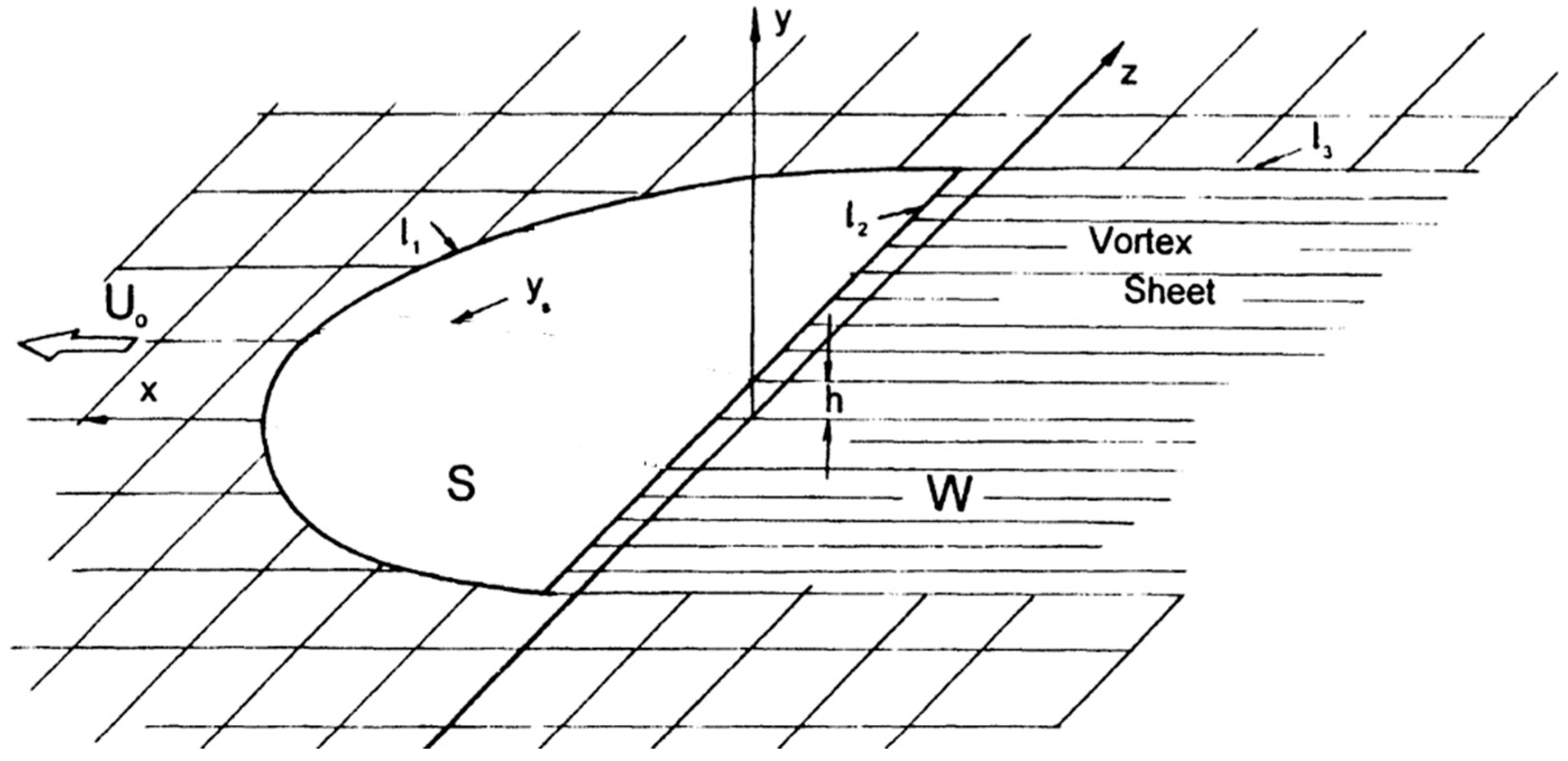
Figure 2.
Derivative for a rectangular wing in extreme ground effect versus aspect ratio for different Strouhal numbers.
Figure 2.
Derivative for a rectangular wing in extreme ground effect versus aspect ratio for different Strouhal numbers.

Figure 3.
Derivative for a rectangular wing versus aspect ratio for different Strouhal numbers.

Figure 4.
Second order derivative of thrust (suction) force coefficient with respect to speed of vertical oscillations .
Figure 4.
Second order derivative of thrust (suction) force coefficient with respect to speed of vertical oscillations .

Figure 5.
Mixed second order derivative of thrust (suction) force coefficient with respect to vertical speed and acceleration .
Figure 5.
Mixed second order derivative of thrust (suction) force coefficient with respect to vertical speed and acceleration .

Figure 6.
Second order derivative of thrust (suction) force coefficient with respect to vertical acceleration .
Figure 6.
Second order derivative of thrust (suction) force coefficient with respect to vertical acceleration .

Figure 7.
Instantaneous thrust (suction) force coefficient for a flat wing of infinite aspect ratio at different Strouhal numbers.
Figure 7.
Instantaneous thrust (suction) force coefficient for a flat wing of infinite aspect ratio at different Strouhal numbers.

Figure 8.
Instantaneous thrust (suction) force coefficient for a flat rectangular wing of finite aspect ratio at different Strouhal numbers.
Figure 8.
Instantaneous thrust (suction) force coefficient for a flat rectangular wing of finite aspect ratio at different Strouhal numbers.

Figure 9.
Period-averaged thrust coefficient for a flat rectangular wing of different aspect ratios in heaving oscillations versus Strouhal numbers.
Figure 9.
Period-averaged thrust coefficient for a flat rectangular wing of different aspect ratios in heaving oscillations versus Strouhal numbers.

Figure 10.
Ideal efficiency of a flat rectangular wing of different aspect ratio in heaving oscillations in extreme ground effect versus Strouhal number. Dashed is the efficiency curve for a heaving foil out of ground effect (Note that the efficiency of heaving foil out of ground effect for a flat plate shown in Figure 10 by dashed line was evaluated with use of classical formula where and are real and imaginary parts of Theodorsen function [1]).

Figure 11.
Ideal efficiency of a rectangular wing heaving in extreme ground effect and out of ground effect [33] for Strouhal numbers tending to zero.
Figure 11.
Ideal efficiency of a rectangular wing heaving in extreme ground effect and out of ground effect [33] for Strouhal numbers tending to zero.

Figure 12.
Derivative for a rectangular wing in extreme ground effect versus aspect ratio for and different Strouhal numbers.
Figure 12.
Derivative for a rectangular wing in extreme ground effect versus aspect ratio for and different Strouhal numbers.

Figure 13.
Derivative for a rectangular wing in extreme ground effect versus aspect ratio for and different Strouhal numbers.
Figure 13.
Derivative for a rectangular wing in extreme ground effect versus aspect ratio for and different Strouhal numbers.

Figure 14.
Period-averaged thrust coefficient of a rectangular wing pitching in extreme ground effect versus Strouhal number for different aspect ratios and .
Figure 14.
Period-averaged thrust coefficient of a rectangular wing pitching in extreme ground effect versus Strouhal number for different aspect ratios and .

Figure 15.
For combined heaving–pitching oscillations versus amplitude ratio and different .

Figure 16.
Ratio of period-averaged thrust coefficient for combined heave–pitch oscillations to that of purely heave oscillations versus amplitude ratio for different phase shift, and aspect ratio .
Figure 16.
Ratio of period-averaged thrust coefficient for combined heave–pitch oscillations to that of purely heave oscillations versus amplitude ratio for different phase shift, and aspect ratio .

Figure 17.
Thrust in the case of combined heaving-pitching oscillations related to that for purely heaving oscillations versus amplitude ratio for different Strouhal numbers.
Figure 17.
Thrust in the case of combined heaving-pitching oscillations related to that for purely heaving oscillations versus amplitude ratio for different Strouhal numbers.

Figure 18.
Period-averaged thrust force coefficient versus Strouhal number for a ring-wing heaving with respect to circular cylinder in extreme ground effect for different ratios of the cylinder radius to the chord.
Figure 18.
Period-averaged thrust force coefficient versus Strouhal number for a ring-wing heaving with respect to circular cylinder in extreme ground effect for different ratios of the cylinder radius to the chord.

Figure 19.
Efficiency of a thrust-generating ring-wing, heaving with respect to a circular cylinder in extreme ground effect for different ratios of the cylinder radius to the chord.
Figure 19.
Efficiency of a thrust-generating ring-wing, heaving with respect to a circular cylinder in extreme ground effect for different ratios of the cylinder radius to the chord.

Disclaimer/Publisher’s Note: The statements, opinions and data contained in all publications are solely those of the individual author(s) and contributor(s) and not of MDPI and/or the editor(s). MDPI and/or the editor(s) disclaim responsibility for any injury to people or property resulting from any ideas, methods, instructions or products referred to in the content. |
© 2023 by the author. Licensee MDPI, Basel, Switzerland. This article is an open access article distributed under the terms and conditions of the Creative Commons Attribution (CC BY) license (https://creativecommons.org/licenses/by/4.0/).
Share and Cite
MDPI and ACS Style
Rozhdestvensky, K. Asymptotic Theory of Flapping Wing Propulsion in Extreme Ground Effect. Appl. Sci. 2023, 13, 690. https://doi.org/10.3390/app13020690
AMA Style
Rozhdestvensky K. Asymptotic Theory of Flapping Wing Propulsion in Extreme Ground Effect. Applied Sciences. 2023; 13(2):690. https://doi.org/10.3390/app13020690
Chicago/Turabian StyleRozhdestvensky, Kirill. 2023. "Asymptotic Theory of Flapping Wing Propulsion in Extreme Ground Effect" Applied Sciences 13, no. 2: 690. https://doi.org/10.3390/app13020690
Note that from the first issue of 2016, this journal uses article numbers instead of page numbers. See further details here.