1. Introduction
A magnetic levitation system is a system that uses magnetic force to overcome gravity to levitate objects. This system makes objects free from their own gravity. Magnetic levitation actuation is a technology that uses a magnetic levitation system to keep the object in and maintain a stable levitation state, and drives the controlled object to perform specific movements in a non-contact manner. The applications of traditional magnetic levitation actuation methods are basically in a liquid environment, and the controlled object is floated on the surface of the liquid or levitated in the liquid by the buoyancy of the liquid when actuated [
1,
2,
3,
4,
5,
6,
7]. The methods in liquid adopt passive levitation, which has great limits in an application environment. These methods are only suitable for a small area near the working point and cannot deal with relatively large-scale position control. Donghak Byun [
8] of the Department of Mechanical Engineering at Chonnam National University in South Korea developed a tadpole-type swimming micro-robot. The micro-robot is actuated by an alternating magnetic field composed of two pairs of vertical Helmholtz coils, and the form of motion is tail swing. The direction and frequency of the tail swing are adjusted by magnetic field changes. Seungmun Jeon [
9] of Hanyang University in South Korea proposed a method that uses a combination of a gradient magnetic field and a uniform magnetic field to actuate a spiral micro-robot. This method provides a new navigation and drilling method for dredging blood vessel blockages. Ye Bo [
10] proposed a magnetic spiral Wireless Capsule Endoscope (WCE) method based on rotating permanent magnets, in which the distance between the external permanent magnet and the magnetic spiral WCE is controlled to basically cancel the gravity and magnetic attraction of the magnetic spiral WCE. Under this condition, the WCE is levitated during the motion.
In the industrial and medical fields, most of the magnetic levitating motion requires precise and larger displacement of active motion control. However, there is no dynamic model for the actuating force generated by the rotating magnetic field in current studies, and the control implementation is insufficient [
11,
12]. Relying on the special structure of the controlled object under the action of an external magnetic field, the object rotates in the liquid to generate a propulsive force, thereby realizing the levitating motion of the controlled object [
13,
14]. Liquid is a considerable limitation. Without liquid, there is no active levitation ability. As a result, the levitating motion obtained by liquid cannot be applied in a non-liquid environment, and the application range of magnetic levitation actuation technology is relatively limited. The only simple and single levitating motion of the controlled object in liquids can be performed using current methods, and the feedback control and programmable trajectory control cannot be achieved. Consequently, the application of the current method is limited. Importantly, the actual operation of the magnetic levitation actuation is mostly applied in the air environment. Active magnetic levitation actuation technology has promising application prospects in practical industrial and medical fields.
For active magnetic levitation actuation technology, Hamal Marino [
15] of the University of Pisa proposed an active magnetic levitation method to achieve controlled helical motion of microrobots in viscous liquid. Maglev ball systems have been extensively studied as applications for active levitation control. Jinggang Zhang [
16] use an integral state feedback control method based on a fuzzy model to realize stable position control of the ball. However, most previous studies have only performed short-distance equilibrium position changes to verify the stability of the levitation [
16,
17,
18]. In the previous research the model-based controller was used, which can achieve the levitating motion control of the permanent magnet ball within a certain range and under a specific step length. However, during the motion process, the fixed Proportion Integration Differentiation (PID) parameters cannot effectively adjust the large position mutation, resulting in excessive overshoot, which causes the controlled ball to vibrate during the step motion. There is severe jittering and even “falling out of control” when using larger step sizes for motion control. Even when using a large step size for motion control there is a violent jitter, and also an uncontrolled fall. There is high adaptability of the neural network to complex systems with nonlinear and ambiguous models. In order to improve the stability of the motion process, the PID controller composed of neurons has stronger adaptability.
The contribution of the paper is presented as follows:
An active magnetic levitation actuation system is built, and a dynamic model of the actuation system based on force imbalance is established. The relationship between the levitating motion of the electromagnetically actuated object and the external magnetic field is revealed in the model;
A controller combining neural network and PID is adopted to control the electromagnetic actuators, in which the PID control parameters are adjusted through a neural network. This controller eliminates the uncertainties of the complex external magnetic field actuation systems and improves the levitating motion tracking performance. Compared with the model-based controller, the combination of neural network algorithm and PID improves the stability of the magnetic levitating motion. The proposed controller is verified in experiments and simulations, and the result proves that the neural network PID control outperforms the model-based controller;
The magnetic levitation actuation and motion control system based on force imbalance can realize non-contact stable levitation. Large-displacement levitating motion of the controlled object in non-magnetic slender pipes can be realized by the proposed step-by-step actuation control method, including other detection and operation equipment attached to the sphere. Non-destructive quality inspection and dredging of the inner wall of slender pipes in the industrial fields can be applied by the control system.
2. System Description
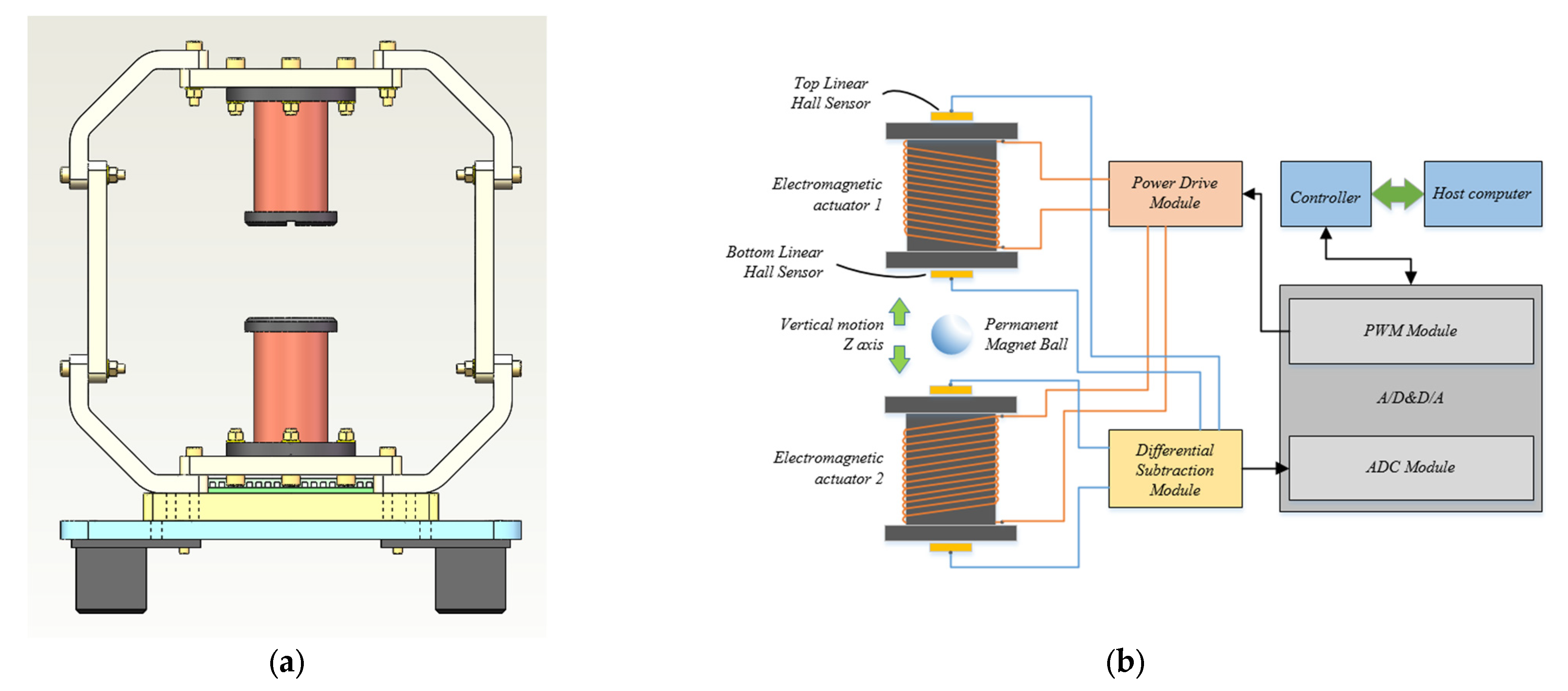
The magnetic levitation actuation and motion control system based on force imbalance consists of a main control unit, power supply modules, electromagnetic actuators, input control modules of current, PWM output modules, differential calculation modules of signals and A/D modules of input signals. The schematic diagram of the magnetic levitation actuation and motion control system based on force imbalance is shown in
Figure 1. The electromagnetic actuator adopts dual electromagnets with a symmetrical layout to generate a superimposed magnetic field to attract the control component of a permanent magnet ball. The system forms a feedback closed loop through the position signals and current signals collected by sensors, so that the control component can move according to the required path and accuracy, thereby realizing the operation and control of the permanent magnet ball in a non-liquid environment. During the actuating process, the ball can move with variable speeds and controllable trajectory.
The parameters of electromagnetic actuators 1 and 2 are the same, which are given in
Table 1. The permanent magnet ball is made of NdFeB, and
Bs = 677.3 mT. In addition, the ball’s radius
r = 6.35 mm and mass
m = 8.15 g.
It can be seen from
Figure 2 that the permanent magnet ball is located on the central axis of the electromagnetic solenoid along the
Z direction, and the electromagnetic force generated by the external magnetic field actuates the ball to move in the direction where the magnetic induction intensity changes most rapidly. The force with cylindrical symmetry in the
XY plane can be ignored because it has a total effect of zero on the permanent magnet ball. From (
∂BZ)/∂
z, the electromagnetic force
F exerted by the hollow solenoid on the permanent magnet ball [
19,
20,
21] is:
where
F denotes the electromagnetic force on the permanent magnet ball;
m denotes the mass of the permanent magnet ball;
B denotes magnetic field of electromagnetic actuators;
denotes gradient;
Bz denotes magnetic field of electromagnetic actuators in vertical direction;
Bs denotes magnetic field of the permanent magnet ball;
Vb denotes the volume of the permanent magnet ball;
μ0 denotes vacuum permeability.
F on the permanent magnet ball is correlated to the current
i and the levitation gap
δ of the permanent magnet ball, and
F is proportional to the magnitude of current
i through the coil from (1). Moreover, the electromagnetic force exerted by the dual electromagnetic actuators on the permanent magnet ball is a superposition of both electromagnetic forces. The dimensionless equation of
F is simplified from (1) based on the external magnetic field actuation, and then the electromagnetic force
F exerted by the dual electromagnetic actuators on the permanent magnet ball is superimposed in the
Z axis direction to obtain the following equation.
where
F (
δ1,
δ2,
i1,
i2) (N) denotes the electromagnetic force on the permanent magnet ball;
X (m) denotes the gap between the electromagnetic actuator 1 and the electromagnetic actuator 2;
i1 and
i2 (A) are, respectively, the excitation currents of the coil windings of the electromagnetic actuator 1 and the electromagnetic actuator 2;
δ1 and
δ2 (m) denote the levitation gap from the center of the permanent magnet ball to the hall sensors at the lower end of the electromagnetic actuator 1 and at the top of the electromagnetic actuator 2, i.e.,
δ1 +
δ2 =
X. The parameters
a1,
a2,
b1,
b2,
c1,
c2,
d1 and
d2 in the (2) are the coefficients determined by the force imbalance control system.
Based on (2) and the principles of Newton’s Second Law, the dynamic equation of the permanent magnet ball is constructed. Within the reasonable range of levitation gap, the nonlinear model is replaced by the approximate linear model to establish the dynamic model of the permanent magnet ball. According to
Figure 3, the dynamic model of the magnetic levitation actuation and motion control system is:
where
kδ1 =
∂F/
∂δ1,
kδ (N/m) is the displacement stiffness coefficient;
ki1 =
∂F/
∂i1,
ki1 (N/A) is the current stiffness coefficient of
i1;
ki2 =
∂F/
∂i2,
ki2 (N/A) is the current stiffness coefficient of
i2;
fd (N) denotes external interference.
3. Control Method
The permanent magnet ball is in equilibrium under the action of dual electromagnets placed vertically. In order to change the displacement of the permanent magnet ball in the vertical position, it is necessary to break the equilibrium of forces acting on the ball. After removing the external magnetic field of the permanent magnet ball and adding the magnetic field instantaneously, the external force and motion of the permanent magnet ball undergo an instantaneous mutation. The process of rebalancing after constant imbalance is called the process of force imbalance. In the process of control, force imbalance is only an instantaneous state of breaking the equilibrium, so it is necessary to accurately control the imbalance and equilibrium of the force. The momentary magnetic imbalance causes the displacement of the permanent magnet ball to change, and the equilibrium is maintained immediately by control. The force control principle that realizes the ball from equilibrium to imbalance and then to equilibrium is called the force imbalance control principle.
Neural network covers comprehensive and diverse fields, including computer vision (including image and video fields), voice fields, text-oriented natural language processing, intelligent actuation, smart cities, medical care, and other aspects of life. It is often used to solve nonlinear systems with uncertainties, which is its area of expertise. Because neural network has good adaptability to complex systems with nonlinear and ambiguous models [
22,
23], it has been widely used in the field of magnetic levitation technology [
24,
25].
Neural network has good tracking performance. PID control with neural network algorithm can change the PID parameters in real time according to the position change of the ball during control, so that the magnetic levitation system always maintains good control ability. The permanent magnet ball obtains a better stable levitation state and levitating motion performance within the levitation range. Neural network PID controller is adopted to actuate a new external magnetic field in the paper, which relies on the actuation principles of force imbalance.
For the magnetic levitation actuation and motion control system, the electromagnetic force is exerted by the electromagnetic actuators on the permanent magnet ball. No matter how the position of the permanent magnet ball changes, the upper electromagnetic force always maintains 2
mg (twice the gravity of the ball), and the lower electromagnetic force always maintains mg. The dynamic models of the electromagnetic actuators 1 and 2 are established, respectively. Laplace transformations are performed on the model, in which the excitation currents
I1(
s) and
I2(
s) are used as input, whilst the vector combination of levitation gaps [
δ1 δ2]
T is the output. The magnetic levitation actuation and motion control system of the permanent magnet ball are established as:
where
ki1 and
ki2 (N/A) are, respectively, the current stiffness coefficients of the upper and lower actuators;
kδ1 and
kδ2 (N/m) are the displacement stiffness coefficients of the upper and lower actuators, respectively;
I1(
s) and
I2(
s) are the Laplace transform of the coil winding currents of electromagnetic actuators 1 and 2, respectively;
δ1(
s) and
δ2(
s) are the Laplace transform of levitation gaps between the permanent magnet ball and electromagnetic actuators 1 and 2.
Establish the state space model of the actuation system as follows:
where
A11 and
A22 are 2 × 2 coefficient matrices;
B is a 4 × 2 coefficient matrix;
C is a 2 × 4 coefficient matrix.
According to the mathematical expression of current stiffness coefficient and displacement stiffness coefficient, as the levitation gap increases, kδ1 and kδ2 decrease first and then increase. When δ1 > 7.702 and δ2 > 7.702 the values of kδ1 are always negative. When δ1 > 0 and δ2 > 0 the values of ki1 and ki2 are always positive. Furthermore, the values of kδ − ki is always less than zero within the set levitating range. Due to the size of the ball, both δ1 and δ2 are greater than 8 mm. According to the Routh Stability Criterion, for the magnetic levitation actuation and motion control system, which is a natural open-loop unstable system, a first term (differential term) must be added to enable the system to achieve stable control.
According to the control models and stability control requirements of the second-order system, neural network PID control is adopted by the magnetic levitation actuation and motion control system actuated, the principles of which are based on force imbalance control theory. The system control block diagram is shown in
Figure 4. The proposed controller is a PID controller with adjustable parameters that are determined by neural network.
The PID controller is formulated as:
The derivative is replaced by the backward difference, and the integral is replaced by the sum of the rectangular areas. The state model of the PID controller is:
where
e(
k) =
δ −
δd,
δ is the current position value of ball,
δd is the desired position value of ball;
k denotes the current state;
u(
k) is the output of neural network PID controller, the physical meaning of which is current
i(
k) of electromagnetic actuator;
k − 1 denotes the previous state;
Kp,
Ki and
Kd represent the adjustment coefficients of the control system, that is, the proportional, integral, and differential coefficients of the neural network PID controller, respectively;
T denotes time constant.
According to the structure of the neural network PID controller, the input equation of controller [
26,
27] is:
The simplified output equation is:
where
wi(
k) denotes the weighting coefficients of the neuron input
xi(
k), i.e., the proportional coefficient
kp, integral coefficient
ki and differential coefficient
kd in (7).
These adjustment coefficients are adjusted by the gradient descent algorithm of neuron weight correction, and the adjustment law is:
where
η denotes the learning rate, and 0 <
η < 1; in general,
∂δ(
k + 1)/
∂u(
k) ≈ (
δ(
k + 1) −
δ(
k))/(
u(
k) −
u(
k − 1)) represents an important coefficient that determines the adjustment direction of the weighting coefficient.
4. Force Imbalance Stable Levitation Test
The overshoot σ% is the primary parameter of the active magnetic levitation actuation system. The actual meaning of the overshoot in the paper is the magnitude of position change of the permanent magnet ball in the vertical direction. The overshoot characterizes the feasibility of the permanent magnet ball’s levitating motion and the stability during the motion. A lower overshoot can enable the controlled ball to obtain more precise position control in practical applications and reduces the possibility of damage to the inspected surface by the controlled object. Therefore, the optimization of the overshoot is the significance of the active magnetic levitation actuation and the premise of the system stability.
ANSYS Maxwell finite element analysis conditions are closer to the test environment. According to the simulation results of
F on the permanent magnet ball, the coefficients
a,
b,
c and
d of (2) are fitted by the least square method. The multi-parameter fitting diagram is shown in
Figure 5. According to the fitting result, the coefficient values of (2) are
a1 =
a2 = 111300.000,
b1 =
b2 = −301.000,
c1 =
c2 = 8.691, and
d1 =
d2 = 4.199. The equation of electromagnetic force
F is exerted on the permanent magnet ball by the electromagnetic actuator, i.e.,
Through calculation, the parameter is determined as
ki1 = 0.14371,
kδ1 = −16.6152,
ki2 = −0.027568,
kδ2 = −4.197625 in (4). According to the actual values of current stiffness coefficients and displacement stiffness coefficients, the coefficient matrices in (5) are:
The neural network PID controller and model-based controller are built in the simulation environment, and the simulation results of overshoot and response time are compared. For the simulation conditions the same mathematical model is used, and the same initial parameters are used for different control methods. The parameter values are kp = −12.6, ki = −9 and kd = −0.84. The error variable is used as the discrete input signal of the neural network PID controller system equation, and the output of the system equation is used as the control variable.
For the simulation results of
Figure 6, the overshoot of step response output of the neural network PID controller of the magnetic levitation actuation and motion control system is 4.9%, and the overshoot of the model-based controller is 7.5%. Magnetic levitating system with the neuron network PID controller has a better stability. The system with dual actuators has a small overshoot and short adjustment time, so the system has good dynamic and static characteristics. The proposed controller parameters are adjusted more stably, indicating that the mechanical structure of the system is more reasonable, the control method is more applicable, and the tracking error of the control system is smaller. The neural network PID controller with dual electromagnetic actuators can realize the stable levitation of the permanent magnet ball. The steady-state error of output signals is less than 0.1%, which meets system performance requirements.
In the actual levitation control, the test is carried out in a static and undisturbed air environment, and the ambient temperature is 20 °C. According to the parameters of electromagnetic actuators in
Table 1, the maximum heating temperature of the coil is within the working temperature range of the sensor. The skeleton of electromagnetic actuators is made of high-performance nylon with excellent thermal insulation performance.
The position control process is shown in
Figure 7. The AH49H type hall sensor is used to collect the position of the permanent magnet ball, and the collection range is ±3000 Gauss. Compared with the laser position sensor and the eddy current sensor, the hall sensor is not affected by the material and light refraction of the detected object and can accurately collect the magnetic field around the permanent magnet ball, making the application scope of active magnetic levitation actuation more extensive. In the process of collecting the magnetic field signal of the permanent magnet ball, the dual-hall sensors are arranged symmetrically in the vertical direction to actively eliminate the influence of the magnetic field of the electromagnetic actuators on the sensors.
It is necessary to collect the magnetic field signal of the ball at high frequency to meet the stable levitation of the ball. Too low acquisition frequency will delay the collected magnetic field signal of the ball, resulting in that the control frequency not keeping up with the frequency of the magnetic field change, causing the ball to vibrate violently or even fall. The software differential has a slow aging time, which affects the control time. Therefore, the OP07 operational amplifiers are used to perform hardware differentials on the voltage signal collected by the dual-hall sensors. The differential result is collected by the 16-bit AD7606, and the data are processed and controlled by the STM32F407 microcontroller. After obtaining the accurate magnetic field signal of the ball, the voltage signal collected by the dual-hall sensors and the actual position of the permanent magnet ball are calibrated. Finally, the corresponding relationship between the position of the permanent magnet ball and the voltage value of the sensors within the levitation range is fitted.
The acquisition accuracy of the AH49H hall sensor is 0.33 mV/Gauss, the calibration accuracy of the test position is 0.002 mm, and the acquisition accuracy of the 16-bit AD7606 is 0.153 mV. The integrated position accuracy of the permanent magnet ball for the test results is 0.002 mm.
The actual levitating control of the magnetic levitation actuation and motion control system is carried out using the designed neural network PID controller, on the premise of the simulation results of the neural network PID control of permanent magnet ball. The control effect of the neural network PID controller on the actual levitating system is studied through experiments. The initial position of the permanent magnet ball is set to −24.50 mm, and the target balance position is set to −20.40 mm. The test results are shown in
Figure 8.
It can be seen from
Figure 8 that the permanent magnet ball can achieve stable levitation. The overshoot of the magnetic levitation actuation and motion control system using the neural network PID controller is 5.8%, and the step length is 4.1 mm. The position fluctuation ranges of the permanent magnet ball controlled by the neural network PID controller is 0.31 mm after stable levitation, and the position fluctuation range controlled by the digital PID controller is 0.64 mm after stable levitation. The overshoot using the model-based controller is 7.7%. Comparative test results of the maglev ball system in Literature [
18] were collected. The overshoot using sliding mode control is 8.5%, and the overshoot of particle swarm sliding mode-fuzzy PID is 6.7%. The step length of the test results of the two controllers is 2 mm. Compared with these two control systems, the magnetic levitation motion control system proposed in this paper has better system performance by optimizing the actuation structure and control method. By using the neural network PID controller, the magnetic levitation actuation and motion control system has more stable and accurate dynamic and static outputs, better characteristics and stronger anti-interference ability. The neural network PID controller is more suitable for the system.
The test conditions will become inconsistent due to the difference between the simulation model and the actual model. The difference between test results and the simulation results is caused by the shape errors and test condition errors, but the errors are within the allowable range. The actually stable levitation effect of the permanent magnet ball is shown in
Figure 9.
5. Force Imbalance Levitating Motion Control Test
After achieving the stable levitation, the step-by-step actuation control method is used to realize the long-distance levitating motion control of a permanent magnet ball. Within the control range of the levitation system, the continuous levitating motion is divided into a series of discrete transition points. The position of each discrete point can be derived from the electromagnetic force equation through the system model. Then, the controller parameters of each transition point are obtained through adjustment. For stability of the controlled object, the continuous position of the permanent magnet ball among the transition points is used to realize the actuation, and the control parameters are quickly updated at each step input signal to ensure the levitating stability of the ball at each transition point.
In order to better observe the control effect of the neural network PID controller, the sine signal of
T = 2π s and square wave signal of
T = 10 s are used to track and analyze the characteristics of the controller. The simulation results shown in
Figure 10 show that the input signal responded well to the control system, and the stable levitation control of the controlled object can be achieved well. The system has a fast response speed and a small tracking error, so it has good dynamic and static performance.
For step-by-step actuation control, when the permanent magnet ball directly responds to a large step input signal, due to the non-linear relationship between electromagnetic force on the permanent magnet ball exerted by the actuators and levitation gap, the ball is prone to drop out of control. In addition, the significant overshoot means that the controlled object’s dynamic and static characteristics are not stable and accurate. In order to study the effect of different step inputs on the motion performance, the step inputs are set to 1.0 mm, 0.5 mm and 0.2 mm, respectively. The test results are shown in
Figure 11 for the descending motion of the permanent magnet ball from the −19.40 mm to the −20.40 mm and the ascending motion from the −20.40 mm to the −19.40 mm.
As can be seen from
Figure 11, whether the permanent magnet ball is rising or falling, compared with the direct response, the overshoot of the step response is reduced significantly by using the step-by-step levitating motion control method. The smaller the step is input, the smaller the overshoot becomes. The adjustment time of the step-by-step control is a bit longer than the continuous control, but the step response process is more stable and accurate.
The reliability of test results of different step inputs is verified by 10 sets of repeatability tests. The repeatability test results of the descending motion are shown in
Table 2, and the repeatability test results of the ascending motion are shown in
Table 3. In
Table 2 and
Table 3,
σ% denotes overshoot, t denotes adjustment time, AVG represents average standard, and
σ denotes deviation.
It can be seen from
Table 3 that during the descending motion, and compared with the 1.0 mm step input, the overshoot of 0.5 mm step input is reduced by 37.3% and the adjustment time is increased by 34.3%. Compared with the 1.0 mm step input, the overshoot of 0.2 mm step length is reduced by 75.4% and the adjustment time is increased by 37.9%. It can be seen from
Table 3 that during the ascending motion, and compared to the 1.0 mm step input, the overshoot of 0.5 mm step input is reduced by 42.7% and the adjustment time is increased by 29.7%. Compared to the 1.0 mm step input, the overshoot of 0.2 mm step length is reduced by 74.9% and the adjustment time is increased by 31.1%. The 2 pairs of 10 sets of repeatability test data meet the 3
σ criterion.
According to the test data in
Table 2 and
Table 3, plot the change curves of the overshoot and adjustment time of three step inputs in the descending and ascending motion process shown in
Figure 12 and
Figure 13. The repeatability test results of the descending motion are consistent with the test results shown in
Figure 11a, and the repeatability test results of the ascending motion are consistent with the test results shown in
Figure 11b. In
Figure 12 and
Figure 13,
l1 represents overshoot of 1.0 mm step input,
l2 represents overshoot of 0.5 mm step input,
l3 represents overshoot of 0.2 mm step input,
l4 represents adjustment time of 1.0 mm step input,
l5 represents adjustment time of 0.5 mm step input,
l6 represents adjustment time of 0.2 mm step input. Dotted line AVG denotes average value.
When the error band is set to ±0.02 mm for more precise levitation, the adjustment time of the 10 sets of test with a step input of 0.2 mm are greatly affected by the adjustment time evaluation standard, which in turn leads to a certain standard deviation of the adjustment time of the 10 sets of test. The analysis results are applicable to descending and ascending motion.
For a large displacement of stable levitation motion, the effect of the levitating motion during descending motion is shown in
Figure 14. The hall sensor near the permanent magnet ball on the electromagnetic actuator #1 is the coordinate origin. The controllable levitation distance of the active magnetic levitation actuation system in the vertical direction is from −34.5 mm to −9.5 mm, and the total levitation range is 25 mm.
Step-by-step actuation control is engaged in for the position control of the permanent magnet ball to realize large displacement motion and step length is set as 0.5 mm.
Figure 15 shows the evolution of the tracking trajectory of the permanent magnet ball that responds to some step inputs with predetermined time intervals. Before every step input, values of controller parameters have been already updated. It can be observed that the large-displacement motion is divided into multi-segment successive small-displacement motion by step-by-step actuation control, and the large-displacement motion of the permanent magnet ball is realized successfully and stably.


