Abstract
Damaged edges of bone tag images contain external factors such as impurities and damage, which affect the stitching process and lead to repair errors. Therefore, this paper proposes a stitching method based on image edge position feature matching. The objective is to improve the accuracy of image stitching by matching feature points based on the position of the image edge pixel so as to solve the accurate stitching of broken edge contour. In the first step of this method, the image containing the broken edge is preprocessed by edge detection, and the location of the broken edge pixel is proposed. Secondly, the feature descriptors were calculated to extract the shape and texture information of the feature points on the fracture edge. Finally, the feature points are optimized by minimum correction and image mosaic is carried out. In terms of image stitching, pre-registration is performed by finding the feature descriptors that are most similar to the edge of the optimum fracture surface profile. The matching operator is added to the overlapping region to obtain the corrected image, and the panoramic image mosaic of the image fracture surface is performed. The experimental results show that feature descriptor matching can ensure the integrity of the fracture, improve the matching accuracy, optimize the uneven deformation of the fracture, ensure the quality of image stitching, and reduce the degree of image distortion.
1. Introduction
The bone tag unearthed in the Weiyang Palace of Chang’an City in the Han Dynasty is of great significance for the study of the official culture of the Han Dynasty. Due to the different shapes of bone tag fragments, manual splicing of bone tag fragments is time-consuming and labor-intensive, especially the splicing of tiny bone tag fragments. Wrong splicing is prone to occur in the long-term splicing state. With the development of science and technology and digital information, the digital restoration technology of cultural relics is increasing day by day. Therefore, the research on the digital splicing of the bone tag has become imperative work, and at the same time, the splicing of micro and small cultural relic fragments has extremely important practical significance. Image stitching [1] is the connection of images in the broken part of the image or the same scene so that it can be completely fused [2] to form a complete image, which is an important step in image restoration and restoration. Image stitching is the registration of a group of images with interrelationships from different viewing angles or the same viewing angle, and then sampling and fusing image information to form a wide viewing angle, complete, high-definition new image technology containing image information. Image stitching must be visually reasonable, and attention should be paid to the details of feature descriptor extraction, especially in the broken part of the image.
In the research of image edge detection [3], Roberts, Prewitt, Sobel, Canny, etc. [4] are effective edge detection operators. The Roberts operator has accurate edge location but is sensitive to image noise. The image noise has a smoothing effect, but the location of the edge is not clear. The Sobel operator can eliminate the influence of image noise, but the distinction between the subject and the background is not clear [5], and the Canny operator [6] has a good signal to noise. Compared with the inspection accuracy, the localization is strong, and its edge detection standard is relatively strict. It is a multi-stage optimization operator with filtering, enhancement and detection [7]. In the study of image feature descriptor matching, Harris et al. [8] proposed a feature-based registration algorithm. Compared with the phase correlation method, the algorithm improved the matching speed and accuracy, but the Harris response function. The calculation is related to the empirical value and lacks stability. In 2010, Calonder et al. [9] proposed a binary feature descriptor for fast computation and expression. In the ever-increasing real-time requirements, the ORB algorithm [10] also appeared, which can meet the real-time requirements, but it does not. With scale invariance, the application scenarios are constantly limited. In the study of image stitching technology, Wang et al. [11] aimed at pottery fragments with missing geometric information, the splash line method was used to extract the texture feature lines of the fragments, sample the dense points of the 3D model, and sputter two depths with different parameters, image, and generate graphics according to the difference between the two images, and complete the stitching of the images. Lin et al. [12] proposed a Smoothly Varying Affine (SVA) transformation for better local adaptation. Chen et al. proposed a Global Similarity Prior (GSP)-based warping [13] by minimizing the energy function consisting of aligned, local and global similarity terms; their method was designed to account for distortions in non-overlapping regions but linearly. The structure is not well protected. Zhang et al. constructed a global stitched image by composing a global objective function through alignment and a set of prior constraints, allowing a wide baseline of image and non-planar scene structures [14]. Lin et al. considered differences in pixel intensities instead of the well-known Euclidean distance, which works well in low-texture images [15]. Li et al. proposed Quasi-Homography (QH) warping [16], which effectively balances the distortion in non-overlapping regions and facilitates the creation of natural-looking panoramas. However, scenes with large parallax [17] are not flexible enough to reduce distortion.
In this paper, an image-splicing method corresponding to the fracture location is proposed. In order to overcome the inaccuracy of splicing the fracture edges of bone picks, feature points are extracted and matched with the edge texture feature information, and then pixel position splicing is completed. The real-time stitching of different bone sign image backgrounds was carried out, and the effect was compared with that of manual stitching. A splicing method is established in the region of the image fracture position. By detecting the edge of the image fracture position, feature descriptors are extracted, and pixel positions are matched, and edge features are applied to edge position splicing. The main contribution is to propose an accurate stitching method of edge pixel position, which can deal well with the problem of the uneven damaged position of the image and reduce the situation of dislocation stitching. The advantage of this method is that, when stitching the image fracture position, the feature descriptor of the image fracture position is extracted by detecting the contour edge of the image, and then the feature descriptor pair is matched to align the position points of the image fracture edge, and the best pixel position is stitched to ensure the integrity of the stitching image.
2. Basic Method
2.1. Contour Edge Calculation
The purpose of the image binarization processing [18] is to effectively extract the edge texture [19] information of the fracture surface when using the edge detection algorithm so as to prevent the interference of the non-edge texture information of the image. The image binarization processing needs to perform the difference calculation in the horizontal and vertical directions to highlight the edge information. The horizontal direction is recorded as the direction, and the vertical direction is recorded as the Y direction. The and direction operators are shown in Formula (1)
Traverse the image pixels, define a box filter with a size of 3 × 3, and calculate the filter difference in the direction and the direction of the pixel, respectively. The calculation method is as follows:
In which, and correspond to the width and height of the image pixel coordinate point position, the value range of is , and the value range of is . After obtaining and , calculate the edge difference of the entire image, the calculation formula is (4)
The image edge difference of is inserted into the image, and the difference in the image is normalized to prevent the difference from exceeding the range of 0–1.
The Canny operator has a balance between denoising and edge details of the image and can be an ideal edge detection operator. The principle of edge detection is to select an appropriate Gaussian function to smooth the pixels of the image row and column and filter the noise. At this time, the normalized image is , and the gradient magnitude and direction of each pixel are calculated. The differential operator adopts and , and the pixel gradient is set to . The calculation formulas of the pixel gradient magnitude and direction are as follows:
Perform non-maximum suppression operation on the gradient image, eliminate the stray noise in the process of image edge detection, calculate the high and low thresholds of the gradient edge pixels, and process the image pixels after the maximum value suppression according to the high and low thresholds. The maximum value suppression pixel grayscale is set to 0, the pixel grayscale greater than the high threshold is set to 1, and the pixels between the high and low thresholds are recorded as weak edge pixels to ensure the distinction between image texture and non-texture information. For accurate edge results, weak edges need to be suppressed. Comparing each pixel Gradient direction pixel values in the surrounding 8 neighborhoods, the magnitudes of both pixels in the gradient direction are less than . It is an edge pixel; otherwise, the edge pixel is filled, and its gradient value is set to 0.
2.2. Feature Descriptors
In this paper, the ORB algorithm is used to extract feature descriptors. The ORB algorithm [20] is improved on the basis of the FAST algorithm [21]. The advantage lies in the efficient completion of feature extraction and feature description. Rotation invariance. The algorithm adopts binary description, which reduces storage space, improves the speed of feature descriptor generation, and reduces the time required for feature matching. The feature key points are in the prominent area of the image, and the ORB algorithm finds a special area in the image and calculates the corresponding feature vector for each key point, which can identify specific objects in the image.
ORB determines the feature vector by the moment method, takes the feature point as the center of the circle, sets the feature point area with radius r, the moment method finds the centroid of all feature points in the area, and connects the feature point and the centroid to form a vector, this vector is used as the feature direction vector. The method of moments is defined as follows:
On an edge-detected patch, is the gray value at and is the moment of the image. The centroid of the image block is calculated by the method of moments, and the coordinates are
Connect the geometric center O and the centroid of the image block to obtain a direction vector, take the feature point as the original coordinate, and obtain a direction angle, which is defined as
The orientation angle of the feature points of each ORB image patch can be represented by . When ORB calculates the feature descriptor, it is expressed in binary and is defined as
In which, and are the grayscale values of a pair of points at respectively.
While ORB extracts feature descriptors, it has the characteristics of rotation invariance and scale invariance. Scale invariance is to perform Gaussian blur transformation of different scales on the image, down-sampling, and performing FAST feature point detection for each layer of pyramids. Obtain the key points of images of different scales, and finally extract the sum of the feature points from n images of different scales as the image feature descriptor. ORB assigns orientations to key points, creating the same vector regardless of the orientation of the key points, making it rotationally invariant.
2.3. Image Stitching
In the process of image matching [22,23], the existence of wrong matching points often affects the matching accuracy, resulting in blurred fusion [24] of noise edge pixels. The ideal image stitching line is the minimum line of color and structural strength difference in the overlapping area of the image-breaking position. The minimum line of the image-breaking position is defined as follows:
In which, represents the difference between the color values of overlapping pixels, represents the difference in the structural strength. The structural strength difference is realized by modifying the gradient operator. The gradient operator in the horizontal and vertical directions of the image is Formula (1). Assumed reference image and target image , but , it is the product of the gradient difference between the two images in the horizontal and vertical directions. According to the feature descriptor, Equation (11) is used to calculate the minimum line difference of pixel color and structural strength difference. Line i, where the current pixel is located, is obtained according to the location of the broken pixel (x,y), and the pixel values at (x + 1,y − 1), (x + 1,y) and (x + 1,y + 1) of the next line i + 1 are obtained, respectively. The SAD algorithm is used to calculate pixel matching, and the matching values are S1, S2 and S3. Take the pixel with the smallest matching value and the broken pixel (x,y) to calculate Equation (11), replace the most similar pixel to the position of the broken pixel, calculate the position of the next broken pixel, and constantly update the pixel adjacent to the broken position as the replacement pixel for position stitching. In order to avoid large error points caused by the connection at the fracture position, the extension conditions were appropriately restricted for the connection line at the fracture position, and the matching result value was compared with the mean value of the adjacent 3 pixels to prevent the pixel matching replacement error from being too large. Combined with the pair of feature descriptors, the direction of the extended method can be controlled and corrected by the feature descriptors [25].
3. The Proposed Algorithm
In the process of computational vision image processing, it is easily affected by the external environment, such as light intensity, humidity, and shooting angle. Smoothing, removing noise, extracting feature points, confirming similar pixels on the edge of the image, and finally performing image stitching processing, etc., improve the image processing process, reduce errors from external environmental factors, and ensure that image processing is practical and real-time (Figure 1).
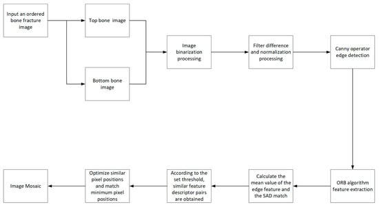
Figure 1.
Algorithm flow.
The overall algorithm implementation steps are as follows:
Input: ordered fracture edge bone tag images, divided into upper and lower parts, the number is equal, upper part , the lower part
Output: stitching complete image
Step 1: Binarize all images according to Contour edge calculation, process the horizontal and vertical directions of image pixels and perform pixel box filtering to calculate the filtering difference and normalization of image pixels, get , highlight the image edge, and facilitate image edge detection.
Step 2: Use the Canny operator to extract the edge of the binarized image , perform Gaussian smoothing on the image row and column pixels, calculate the row and column pixel gradient, distinguish weak and strong pixels, and clarify the texture information and non-texture information of the image edge.
Step 3: ORB builds an image pyramid, collects image features of different resolutions, obtains the key points of each layer of the pyramid image, summarizes the keys of all levels, assigns the direction of the key points, creates the feature vector of the key points, calculates the feature description, and facilitates the extraction of feature points.
Step 4: Use the SAD algorithm to calculate the average similarity value of the R, G, and B channels of all image edge pixels, and set the high and low thresholds; the ORB feature description point extracts the corresponding pixel position, calculates the average pixel similarity value, and judges that the pixel average similarity is within the threshold value. The range is used as a feature descriptor pair for image edge pixel splicing points.
Step 5: Extract the image edge feature points in Step 4, calculate the minimum line of pixel color and structural strength difference, and then combine the horizontal and vertical gradient operators to calculate the line-by-line, pixel-by-pixel color of the image edge and the minimum line difference of structural strength. Calculate, obtain the minimum difference, and update it as the position of the image edge breaking point. When calculating the minimum difference intensity pixel by pixel, similar pixels can be controlled and corrected downward, and finally, filled in accordance with the edge position of similar pixels, a Panoramic Mosaic image is obtained.
4. Experimental Results and Analysis
The purpose of edge detection is to detect the fracture edge of bone tag images. Figure 2 is the Canny edge detection. In addition to the contour edge texture information, the image contains too much non-edge texture information, with stray noise information, which is highly disturbing to the feature point matching. Multiple mismatch points, resulting in error effects.
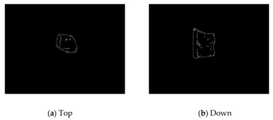
Figure 2.
Canny edge detection.
In order to highlight the edge pixels, the binarized image can reduce the pixel texture information inside the bone tag image. Figure 3 is the edge detection image of the Canny algorithm after binarization. Compared with Figure 2, the contour edge texture is more obvious, and there is not too much texture information in the image. When extracting feature points, the accuracy of matching points is improved. Reduce the impact of noisy environments.
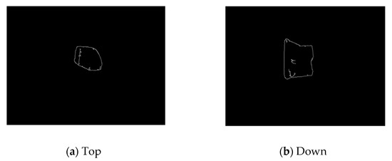
Figure 3.
Binarized Canny edge detection.
In the experiment, the position of the matching interval was adjusted for many times, so that there were more points at the edge break and the feature points were evenly distributed. The experimental results show the performance difference between the ORB method in this paper and the traditional ORB method in feature point extraction, as shown in Figure 4 and Figure 5. It is clearly evident from Figure 4 that the problem of matching the corresponding position of the feature points occurs when there is a matching situation of feature points within the edge contour.
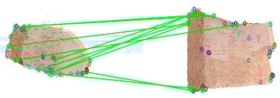
Figure 4.
ORB feature extraction.
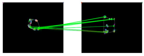
Figure 5.
Binarized ORB Feature Extraction.
As shown in Figure 5, the ORB feature point extraction has fewer feature points in the contour and is evenly distributed at the edge of the contour, which can well suppress the phenomenon of feature point aggregation, and the matching accuracy of feature points on the edge of the contour is high.
SAD is one of many similarity-matching algorithms. The implementation method of SAD is simple and has the characteristics of real-time. According to the feature obtained by the ORB algorithm, the sub-pixel position is described, and the pixel value similarity matching using SAD can improve the matching accuracy. When using feature points for matching and connection, due to the single pixel of the bone tag image, there are many cracks and traces of ancient characters in the bone tag, and the difference between the pixels on the fracture edge of the bone tag is small, which leads to the extraction of feature points, which is easy to extract errors, resulting in errors. Therefore, when extracting feature point pairs, select the 10 pairs with the highest accuracy area for comparison in order to prevent less error accuracy. It is clearly evident from Figure 6 that the 10 feature descriptor pairs with the highest accurate area range.
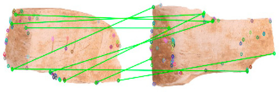
Figure 6.
Traditional ORB feature matching.
The unmatched feature descriptor pairs have large feature errors, which affect the splicing and accuracy. Figure 7 is the matching situation of the feature descriptor pair in this paper. It can be clearly seen that the image edge matching situation is better, thereby improving the image stitching accuracy. It is proved that the SAD matching algorithm used in this paper can effectively improve the matching accuracy of the edge region and improve the low matching accuracy in the solid color edge region.
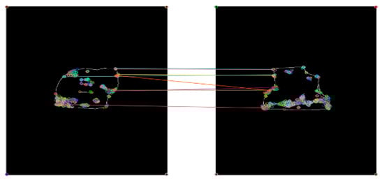
Figure 7.
Binarized ORB feature matching.
In terms of the overall splicing effect, Figure 8 uses the feature descriptor of the traditional ORB algorithm, and there is a large gap in the splicing of the image fracture edge, and there is an error in the splicing of the feature descriptor. Follow-up research has implications.(a), (b), (c), (d) are the splicing effect pictures of different fractured bone tags.
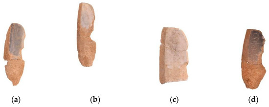
Figure 8.
Traditional ORB splicing.
In Figure 9, after the sub-pixel positions are matched in the feature description, there is a one-to-one correspondence between the pixel positions of the fracture edge and the pixel positions overlap, which significantly improves the accuracy of the stitched image. In this paper, in the case of obvious edge texture features, the matching results are better than the traditional ORB algorithm feature matching.(a), (b), (c), (d) are the splicing effect pictures of different fractured bone tags.
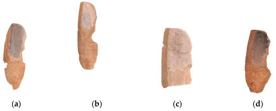
Figure 9.
ORB splicing for edge texture.
According to the order from left to right in Figure 8 and Figure 9, the splicing results of the feature descriptor pairs are a, b, c, and d in turn. Table 1 shows the matching accuracy of the feature descriptor pairs. It can be seen that the binarization in the text The accuracy of the ORB feature descriptor extraction method is higher than that of the ORB feature descriptor extraction method, but the accuracy is not above 90%. It is white, which has a certain influence on the extraction of feature descriptors, but the algorithm in this paper has a research effect on the extraction of feature descriptors.

Table 1.
Feature descriptor pair matching accuracy.
In order to compare the splicing effect between the algorithms and objectively reflect the richness of the image information, the information entropy of the pixel value of the spliced image is used to evaluate the spliced image. In general, the larger the image information entropy, the richer the information and the better the quality of the stitched image. Table 2 shows the information entropy values of the image stitching results. Compared with Table 1, it can be found that the image stitching quality of the algorithm in this paper is significantly higher than that of the traditional ORB algorithm. Due to the influence of artificial repair factors on the contour edge of the image, it has a certain impact on the image stitching quality, and there is also image information entropy. In the case of incorrect calculation, the traditional algorithm is similar to the calculation result of the information entropy of the stitched image in the algorithm in this paper. Overall comparison, the algorithm in this paper has advantages in image stitching compared with traditional algorithms.
Table 2.
Information entropy of different splicing algorithms.
In Table 3, 200 groups of valid bone tag images were extracted in the limited range of bone tag images. In each group of images, the number of extracted feature point descriptor pairs was different due to the different degrees of fracture edge. Statistical analysis was made on the feature point descriptor pairs of the whole image, and matching results of the feature descriptor pairs were analyzed according to similar pixels of bone tag. It is concluded that the matching result of the proposed algorithm is better than the feature descriptor pair extracted by the traditional ORB algorithm.
Table 3.
200 pairs of bone tag tabs match each other.
In order to fully illustrate the rationality of the algorithm, an image enhancement experiment is added. The image data enhancement operation of rotation and Gaussian blurring can be seen on Figure 10. Figure 10b shows that when the traditional Canny algorithm is used for edge detection, the internal texture information of the bone tag is more obvious, and there is a risk of matching errors in the matching of feature descriptor pairs. Figure 10c shows that the importance of bone tags’ edge texture information, and it is not easy to cause splicing errors when ORB extracts feature descriptor pairs. Because the large splicing gap leads to a large matching error, the splicing effect of Figure 10e is significantly higher than that of Figure 10d in order to narrow the splicing gap at the broken edge of the bone tag. Comparing the above edge detection and image splicing effects, the algorithm in this paper has an obvious advantage.
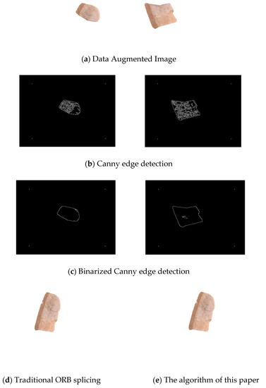
Figure 10.
Enhanced image stitching.
5. Conclusions
During the splicing process, it is interfered with by the bone tag image collection environment and method, which affects the image feature extraction and matching, and may need to be manually corrected. The algorithm proposed in this paper is based on the edge feature of the image fracture surface. The algorithm performs binary Canny operator edge extraction on the reference image and the target image, uses the ORB algorithm to extract the image features, confirms the features between the reference image and the target image, matches the image contour edge feature points with pixels, and further performs fusion processing on the stitched image. The algorithm in this paper solves the influence of noise, low brightness and low resolution on the stitching accuracy of the image contour edge, matches the similarity of the feature description sub-pixels, locally optimizes the fracture edge of the bone tag image, and improves the pixel position overlap accuracy. Good effect, splicing according to the correct fracture position, preventing pixel position splicing errors during the splicing process of bone tags, and manually repairing the error repair of the missing parts of the tiny edges of the bone tags. In the implementation of the algorithm in this paper, there are also certain errors, such as feature descriptor extraction, the image pixel color is relatively single, the background is white, the background and foreground color of the image having no obvious color contrast, and the edge of the image contour is manually repaired, causing errors. Position extraction has an impact on the image stitching effect but also provides direction for subsequent research so as to achieve a more accurate stitching effect.
Author Contributions
Conceptualization, H.W. and T.W.; methodology, T.W. and K.W.; software, T.W.; validation, T.W., K.W. and Z.Y.; formal analysis, T.W.; investigation, Z.Y.; resources, T.W.; data curation, T.W.; writing—original draft preparation, T.W.; writing—review and editing, T.W.; visualization, T.W.; supervision, K.W.; project administration, H.W.; funding acquisition, H.W. All authors have read and agreed to the published version of the manuscript.
Funding
This research was funded by the National Science Foundation of China (Grant No. Z20210506) and Natural Science Basic Research Plan in Shaanxi Province of China (Program No. 2021JQ-495).
Institutional Review Board Statement
This study did not require ethical approval for not involving humans or animals.
Informed Consent Statement
Not applicable.
Data Availability Statement
The simulation experiment data used to support the findings of this study are available from the corresponding author upon request.
Acknowledgments
This work was supported in part by the National Science Foundation of China (Grant No. Z20210506). The Project was supported by the Natural Science Basic Research Plan in Shaanxi Province of China (Program No.2021JQ-495). All individuals included in this section have consented to the acknowledgement.
Conflicts of Interest
The authors declare no conflict of interest.
References
- Di, Y.C.; Chen, Y.P.; Chen, Y.Y.; Chen, P. Survey on image mosaic algorithm of unmanned aerial vehicle. J. Comput. Appl. 2011, 31, 170–174. [Google Scholar] [CrossRef]
- Pajares, G.; De La Cruz, J.M. Wavelet-based image fusion tutorial. Pattern Recognit. 2004, 37, 1855–1872. [Google Scholar] [CrossRef]
- Wanto, A.; Rizki, S.D.; Andini, S.; Surmayanti, S.; Ginantra, N.L.W.S.R.; Aspan, H. Combination of Sobel+Prewitt Edge Detection Method with Roberts+Canny on Passion Flower Image Identification. J. Phys. Conf. Ser. 2021, 1933, 012037. [Google Scholar] [CrossRef]
- Yu, Y.; Rashidi, M.; Samali, B.; Mohammadi, M.; Nguyen, T.N.; Zhou, X. Crack detection of concrete structures using deep convolutional neural networks optimized by enhanced chicken swarm algorithm. Struct. Health Monit. 2022, 21, 2244–2263. [Google Scholar] [CrossRef]
- Feryanto, Pengenalan Pola Berdasarkan Edge Detection Operator Sobel, Isotropic, Roberts, Prewitt, Kirsch Dengan Position Based Matching dan Backpropagation, Skripsi S-1 Teknik Informatika. 2010. Available online: https://www.semanticscholar.org/paper/Pengenalan-Pola-Berdasarkan-Edge-Detection-Operator-Feryanto/ef1518a40997547b4ac1454794709b63af750ab7 (accessed on 28 December 2022).
- Canny, J. A Computational Approach to Edge Detection. IEEE Trans. Pattern Anal. Mach. Intell. 1986, 8, 679–698. [Google Scholar] [CrossRef] [PubMed]
- He, F.; Ye, Q. A Bearing Fault Diagnosis Method Based on Wavelet Packet Transform and Convolutional Neural Network Optimized by Simulated Annealing Algorithm. Sensors 2022, 22, 1410. [Google Scholar] [CrossRef] [PubMed]
- Harris, C.; Stephens, M. A combined corner and edge detector. Alvey Vis. Conf. 1988, 15, 147–152. [Google Scholar]
- Calonder, M.; Lepetit, V.; Strecha, C.; Fua, P. BRIEF: Binary Robust Independent Elementary Features. In European Conference on Computer Vision; Springer: Berlin/Heidelberg, Germany, 2010; Volume 010, pp. 778–792. [Google Scholar]
- Rublee, E.; Rabaud, V.; Konolige, K.; Bradski, G. ORB: An efficient alternative to SIFT or SURF. In Proceedings of the IEEE International Conference on Computer Vision, Barcelona, Spain, 6–13 November 2011; pp. 2564–2571. [Google Scholar]
- Wang, P.; Geng, G.; Yang, W. Fragment Splicing Method Combined with Surface Texture and Fracture Contour. Comput. Eng. 2019, 45, 315–320. [Google Scholar]
- Lin, W.Y.; Liu, S.; Matsushita, Y.; Ng, T.T.; Cheong, L.F. Smoothly varying affine stitching. In Proceedings of the CVPR 2011, Colorado Springs, CO, USA, 20–25 June 2011; pp. 345–352. [Google Scholar]
- Chen, Y.S.; Chuang, Y.Y. Natural image stitching with the global similarity prior, In European Conference on Computer Vision; Springer: Cham, Switzerland, 2016; pp. 186–201. [Google Scholar]
- Zhang, G.F.; He, Y.; Chen, W.F.; Jia, J.Y.; Bao, H.J. Multi-viewpoint panorama construction with widebaseline images. IEEE Trans. Image Process. 2016, 25, 3099–3111. [Google Scholar] [CrossRef] [PubMed]
- Lin, K.; Jiang, N.J.; Liu, S.C.; Cheong, L.F.; Minh, D.; Lu, J.B. Direct photometric alignment by mesh deformation. In Proceedings of the IEEE Conference on Computer Vision and Pattern Recognition, Honolulu, HI, USA, 21–26 July 2017; pp. 2405–2413. [Google Scholar]
- Li, N.; Xu, Y.; Wang, C. Quasi-homography warps in image stitching. IEEE Trans. Multimed. 2017, 20, 1365–1375. [Google Scholar] [CrossRef]
- Zhao, Y.Y. Image Stitching of the Target Object Based on Large Parallax Images. Mod. Comput. 2015, 11, 42–45. [Google Scholar]
- Tang, T.; Qin, X.; Yi, Z. Image Binarization Processing Method Using -Medoids Clustering. J. Front. Comput. Ence Technol. 2015, 2, 234–241. [Google Scholar]
- Zhao, Y.; Zhu, C.; Chen, Z. Boundary Artifact Reduction in View Synthesis of 3D Video: From Perspective of Texture-Depth Alignment. IEEE Trans. Broadcast. 2011, 57, 510–522. [Google Scholar] [CrossRef]
- Feng, Y.; Li, S. Research on an Image Mosaic Algorithm Based on Improved ORB Feature Combined with SURF. In Proceedings of the Chinese Control And Decision Conference, Shenyang, China, 9–11 June 2018. [Google Scholar]
- Rosten, E.; Drummond, T. Machine learning for highspeed corner detection. In European Conference on Computer Vision; Springer: Berlin/Heidelberg, Germany, 2006; Volume 1. [Google Scholar]
- Noh, M.J.; Cho, W.; Park, J.K. Affine Model for Generating Stereo Mosaic Image from Video Frames. J. Korean Soc. Geo-Spat. Inf. Sci. 2009, 17, 49–56. [Google Scholar]
- Rankov, V.; Locke, R.J.; Edens, R.J. An algorithm for image stitching and blending. In Three-Dimensional and Multidimensional Microscopy; SPIE: Bellingham, WA, USA, 2005; pp. 190–199. [Google Scholar]
- Yuan, X.; Man, P.L.; NgKa, H. Depth map misalignment correction and dilation for DIBR view synthesis. Image Commun. 2013, 28, 1023–1045. [Google Scholar]
- Jiang, R.; Xin, Y.; Chen, Z.; Zhang, Y. A medical big data access control model based on fuzzy trust prediction and regression analysis. Appl. Soft Comput. 2022, 117, 108423. [Google Scholar] [CrossRef]


Disclaimer/Publisher’s Note: The statements, opinions and data contained in all publications are solely those of the individual author(s) and contributor(s) and not of MDPI and/or the editor(s). MDPI and/or the editor(s) disclaim responsibility for any injury to people or property resulting from any ideas, methods, instructions or products referred to in the content. |
© 2023 by the authors. Licensee MDPI, Basel, Switzerland. This article is an open access article distributed under the terms and conditions of the Creative Commons Attribution (CC BY) license (https://creativecommons.org/licenses/by/4.0/).