Abstract
To overcome the instability of the traditional magnesium alloy additive process, the research on oscillating laser-arc hybrid additive manufacturing (O-LHAM) for AZ31 Mg alloy was developed first, and it focused on the effect of beam oscillation on process characteristics, such as macroscopic morphology, porosity defects, microstructure, and mechanical properties of thin-walled components. The increasing oscillation frequency was effective in suppressing the defects, including lack of fusion, wavy hump, internal porosity, etc. Compared with the case without oscillation, the average grain size of O-LHAM samples was refined from 22–32 μm to 18–20 μm at 300 Hz, while the percentage of Al8Mn5 and Mg17Al12 precipitation increased from 1.42–1.61% to 2.55–3.32%. For this reason, a stirring laminar flow was induced using the oscillating laser in the melt pool, with the ability to disrupt the grain structure and provide more nucleation sites, which is beneficial in reducing the average grain size and promoting the precipitation of the precipitated phase. Meanwhile, for the component without pores, the ultimate tensile strength is 205 MPa, slightly less than the base, but the elongation is 20.7%, twice that of the base. The tensile fracture is characterized by a large number of dimples and some ductile tearing ridges, demonstrating good ductility, which is associated with the grain refinement and precipitation strengthening induced using the oscillating laser. The results indicated that O-LHAM would be an effective method for manufacturing Mg alloy fast and well.
1. Introduction
Because of their low density, high strength ratio, and excellent electromagnetic shielding properties, magnesium alloys have been widely used in railway transportation, automotive, and aerospace industries [1,2]. Additive manufacturing is one of the most popular manufacturing technologies for metal components nowadays [3,4,5]. However, magnesium alloys are highly susceptible to macroscopic defects and internal porosity during the rapid non-equilibrium solidification process of the additive manufacturing process due to their low melting/boiling point, high thermal conductivity, high expansion coefficient, and low surface tension [6,7,8]. Therefore, how to improve the quality of magnesium alloy additive components is one of the current urgent issues to be solved.
The traditional magnesium alloy additive manufacturing methods are selective laser melting (SLM) and wire arc additive manufacturing (WAAM). Between these, the SLM process is easier to control and can manufacture precise and complex structural parts. However, limited by the volume of the forming cavity, it is difficult to meet the requirements of efficient manufacturing for large parts. In addition, magnesium alloy powder is flammable and explosive, which also results in there being little research on the SLM of magnesium alloys [9,10,11]. Relatively, WAAM has the characteristics of a high deposition efficiency and unrestricted forming size; thus, it has received wide attention [12]. However, the macroscopic morphology is poor, and grain coarsening is serious in the WAAM of magnesium alloy due to the large heat input from the arc [13]. For example, Takagi. Et al. studied WAAM using a self-developed wire, but the fabricated cubes were very rough due to the low viscosity of the liquid magnesium alloy [14]. Yang et al. used cold metal transition (CMT) to manufacture thin-walled components of magnesium alloy, and the macroscopic formation of the components was significantly improved owing to the reduction of heat input [15]. It is worth noting that the CMT arc reduces the deposition efficiency with a wire feed rate of only 3 m/min. So, a new method needs to be developed to ensure excellent forming along with high deposition efficiency.
Laser arc hybrid additive manufacturing is a new additive manufacturing technology developed in recent years, which contributes to improved component accuracy and quality with less heat accumulation and high production efficiency [16,17]. Zhang et al. have found that laser can stabilize the arc and improve the surface quality effectively in LHAM of aluminum alloy [18]. However, pores are easily formed in the component due to the instability of the laser keyhole [19,20]. To reduce the number of pores, Gong. et al. developed the oscillating laser-arc hybrid additive manufacturing process (O-LHAM), and as a result, the surface roughness of the components obtained using O-LHAM was found to be reduced by 20%, the deposition efficiency was improved by 4 times, and the internal porosity was significantly reduced compared with WAAM [21]. Obviously, O-LHAM has a positive effect on improving the quality of components.
As mentioned above, O-LHAM may have great potential in the additive manufacturing of magnesium alloys, but related studies have not been reported until now. In this paper, the feasibility of using O-LHAM to manufacture thin-walled components of high-quality AZ31 magnesium alloy was proven, and the effect of the oscillating frequency on the macroscopic defects and microstructure of the components was systematically investigated, which helps to deepen the understanding of magnesium alloy O-LHAM and expand its application scope.
2. Experimental Procedures
2.1. Materials and Equipment
The experimental material is AZ31B magnesium alloy, the most widely used at present, which has high strength, good ductility, and corrosion resistance at room temperature. The thickness of the base plate is 5 mm, the diameter of the wire is 1.6 mm, and, as shown in Table 1, its chemical composition was measured using energy-dispersive X-ray spectroscopy (EDS). Before the experiment, the oxide layer on the surface of the base plate was removed using mechanical grinding, and the surface oil was cleaned with acetone.

Table 1.
Chemical composition of the AZ31 magnesium alloy base and wire.
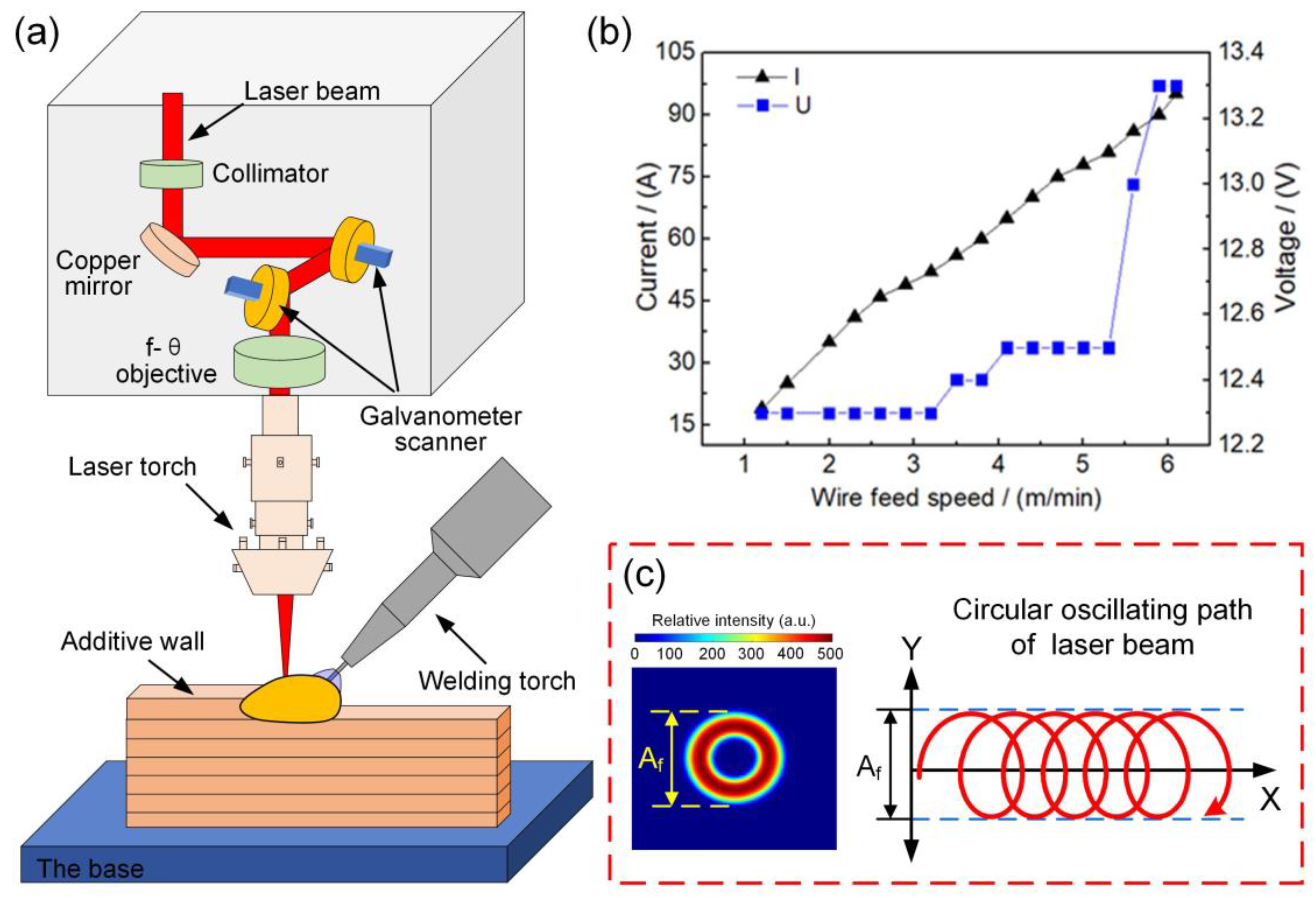
The additive manufacturing system mainly consists of a Fanuc M-710ic industrial robot, Fronius TPS4000 CMT welder, IPG YLS-6000 fiber laser, and a SCANLAB HurrySCAN30 galvanometer. Figure 1a shows the schematic diagram of the oscillating laser-arc hybrid additive manufacturing system. Among them, as shown in Figure 1b, the arc parameters are controlled in a one-dimensional control mode. The current and voltage are automatically matched according to the wire feeding speed, and the CMT arc has a very low heat input, which helps stabilize the additive manufacturing process [22,23]. The oscillation of the laser beam is achieved using the galvanometer. By controlling the motion of the two galvanometers, different oscillation modes can be realized, such as transverse, longitudinal, and circular. A circular pattern was more beneficial for stabilizing the melt pool based on the previous results [24]; therefore, the circular oscillation with a radius of 0.3 mm was used, as shown in Figure 1c. It should be noted that the relationship between the oscillation frequency f (Hz) and the oscillation speed Vf (mm/s) can be expressed by Equation (1).
where Af (mm) is the amplitude of the circular trajectory, and r (mm) is the radius of the circle. When the Af is fixed, the f is proportional to the Vf.
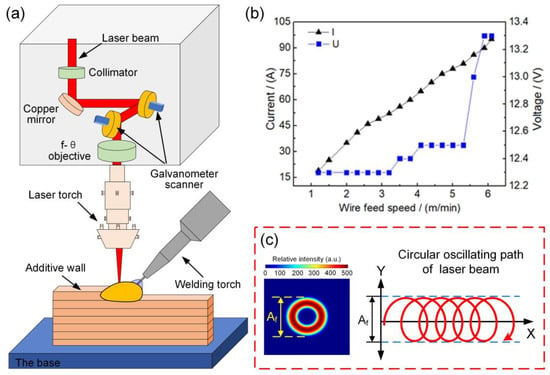
Figure 1.
(a) The schematic diagram of the oscillating laser-arc hybrid additive manufacturing system; (b) the one-dimensional control curve of CMT arc parameters; (c) the circular oscillating path of the laser beam.
The laser beam was always incident vertically during the experiment to ensure a good beam oscillation effect. The tilt angle of the welding torch was about 45 degrees. The relative position of the laser beam to the arc welding torch was always maintained. The CMT arc protective gas was Ar with 99.99% purity, and the gas flow rate was 25 L/min. As shown in Table 2, only the oscillation frequency was changed in this experiment, and other parameters were kept fixed.

Table 2.
Main processing parameters in the additive manufacturing experiment.
2.2. Microstructural Analysis and Mechanical Tests
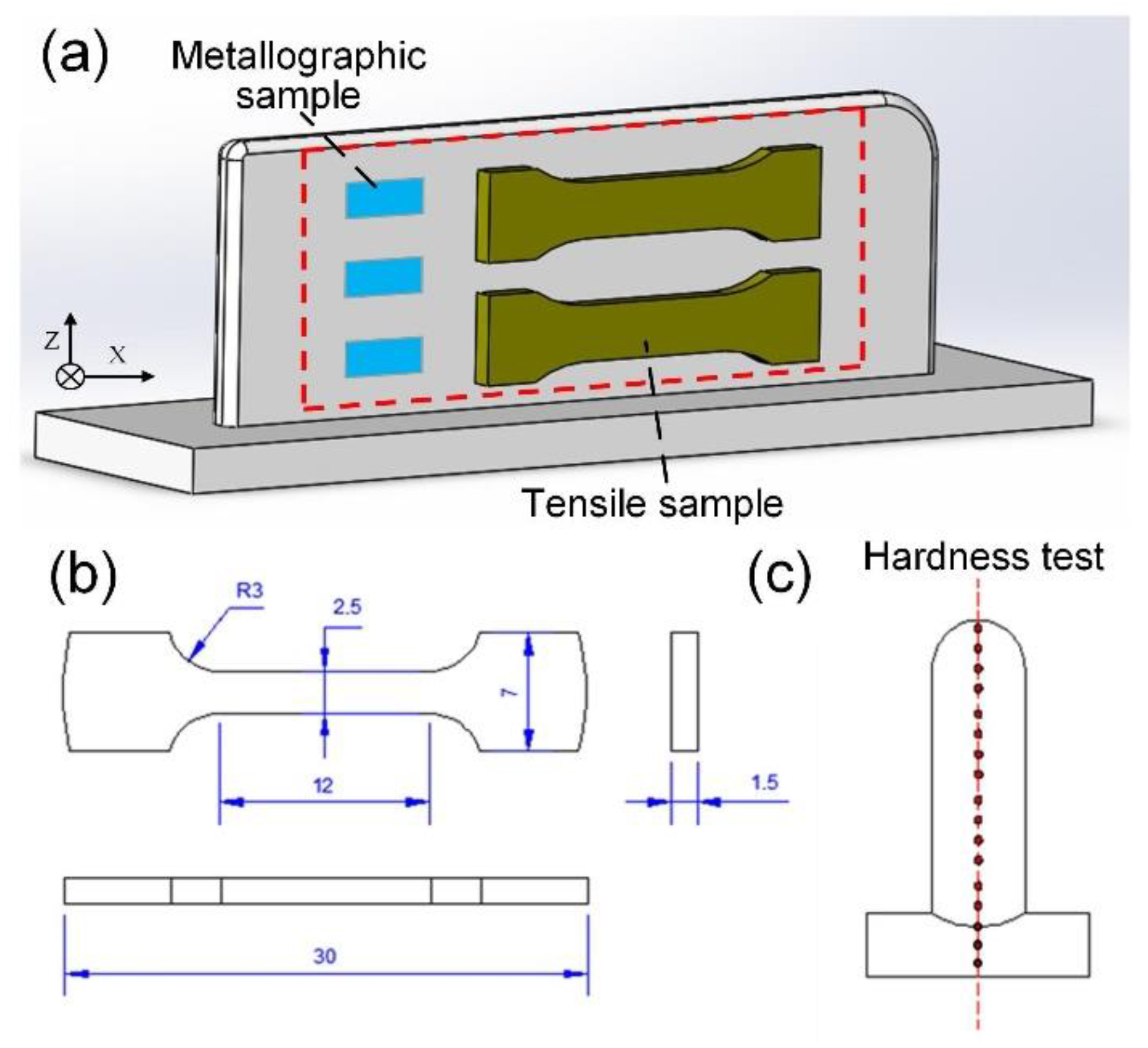
The porosity of the Mg alloy thin-wall components was measured and counted using non-destructive X-ray testing (NDT) and Image-pro plus software, respectively. As shown in Figure 2a, Metallographic samples were obtained using wire-cut electrical discharge machining (WEDM, TiZhou DK7745, Tizhou, China). The samples were pre-ground to #2000 sandpaper using the water-grinding method and then polished with #0.5 polishing paste. Finally, the polished samples were chemically etched, and the etching time was about 30 s (5 g picric acid, 5 mL acetic acid, 10 mL deionized water, 100 mL ethanol). Subsequently, the metallographic samples were scrutinized using optical microscopy (OM, ZEISS DSX968, Oberkochen, Germany) and scanning electron microscopy (SEM, ZEISS EVO18, Oberkochen, Germany) with a secondary electron sensor, and their composition was analyzed with the energy dispersive X-ray spectroscopy (EDS) and corroborated with X-ray diffraction (XRD, PANalytical B.V., Oberkochen, Germany).
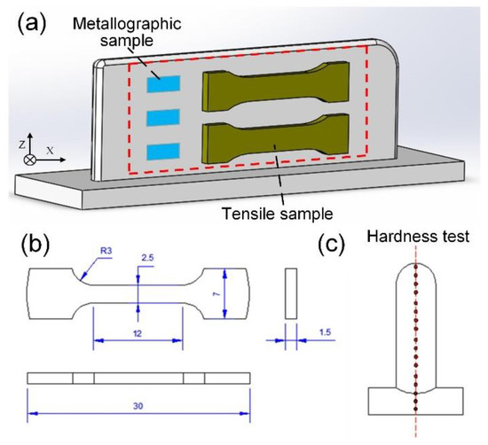
Figure 2.
(a) The position of metallographic and tensile samples; (b) the dimension of tensile test specimens; (c) the position of the hardness test.
The grain size was difficult to characterize due to the irregular shape of the observed grains. In this research, it was assumed that the grain shapes were all circles, and the average grain size could be computed with Equation (2) as follows:
where S is the area of the selected fixed rectangle in the metallographic map, and n is the number of grains (the incomplete grain intercepted on the left and lower edges of the rectangle is counted as one; the incomplete grain intercepted on the right and upper edges are not counted).
As shown in Figure 2c, the Vickers hardness test (SHYZ HV-1000P, Wuhan, China) was performed in the vertical direction of the wall with a test load of 200 g and a load time of 10 s. The AGIC series electronic universal testing machine from SHIMADZU, Japan, was used for tensile testing. The tensile test was performed under a 2 mm/min loading rate at room temperature according to the ASTM E8 standard; the sampling location is shown in Figure 2a, and the dimension is shown in Figure 2b. Lastly, the tensile fracture was observed using SEM, and the fracture morphology was analyzed to investigate the causes and mechanisms of fracture in tensile specimens.
3. Results
3.1. Macroscopic Analysis
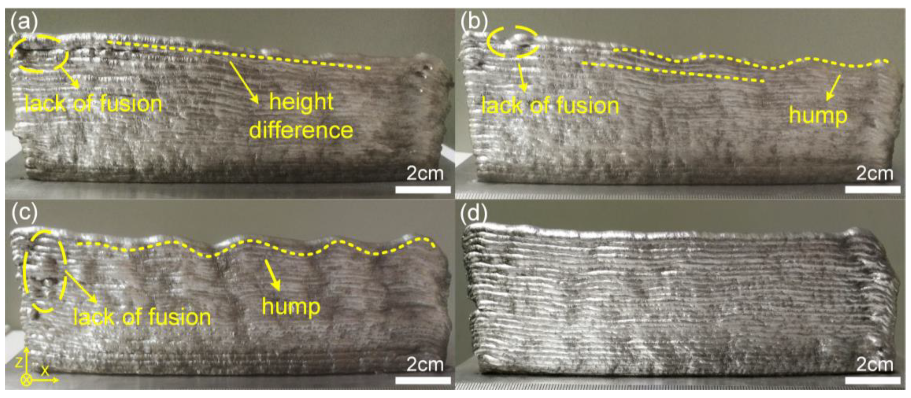
As shown in Figure 3, all of the thin-walled components had some degree of macroscopic defects, such as lack of fusion, hump, and height difference. Due to the low temperature at the arc start, it was difficult for the magnesium alloy to wet and spread, and a lack of fusion usually formed at the head of the component. As the deposition proceeded, heat accumulated in the component, the melt pool spread outward at the closing arc position, and the formed deposition layer collapsed. Therefore, as the deposited layers were stacked, the height difference between the head and the end of the component was formed. Interestingly, as shown in Figure 3a–c, the height difference defect gradually turned into a wavy hump as the oscillation frequency increased from 0 Hz to 200 Hz. Significantly, as shown in Figure 3d, the component at 300 Hz had good macroscopic properties with no collapse, good interlayer fusion, and uniform layer heights, and various macroscopic defects were effectively suppressed. The mechanism of hump defect suppression using beam oscillation is discussed in detail in later sections.
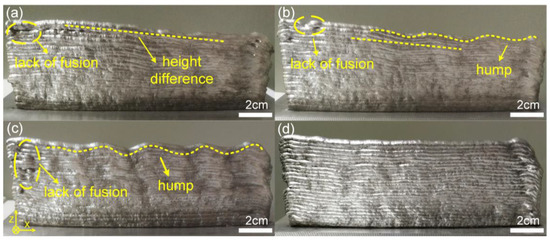
Figure 3.
Macroscopic appearance of AZ31 thin-wall components at different oscillation frequencies. (a) 0 Hz; (b)100 Hz; (c) 200 Hz; (d) 300 Hz.
3.2. X-ray NDT
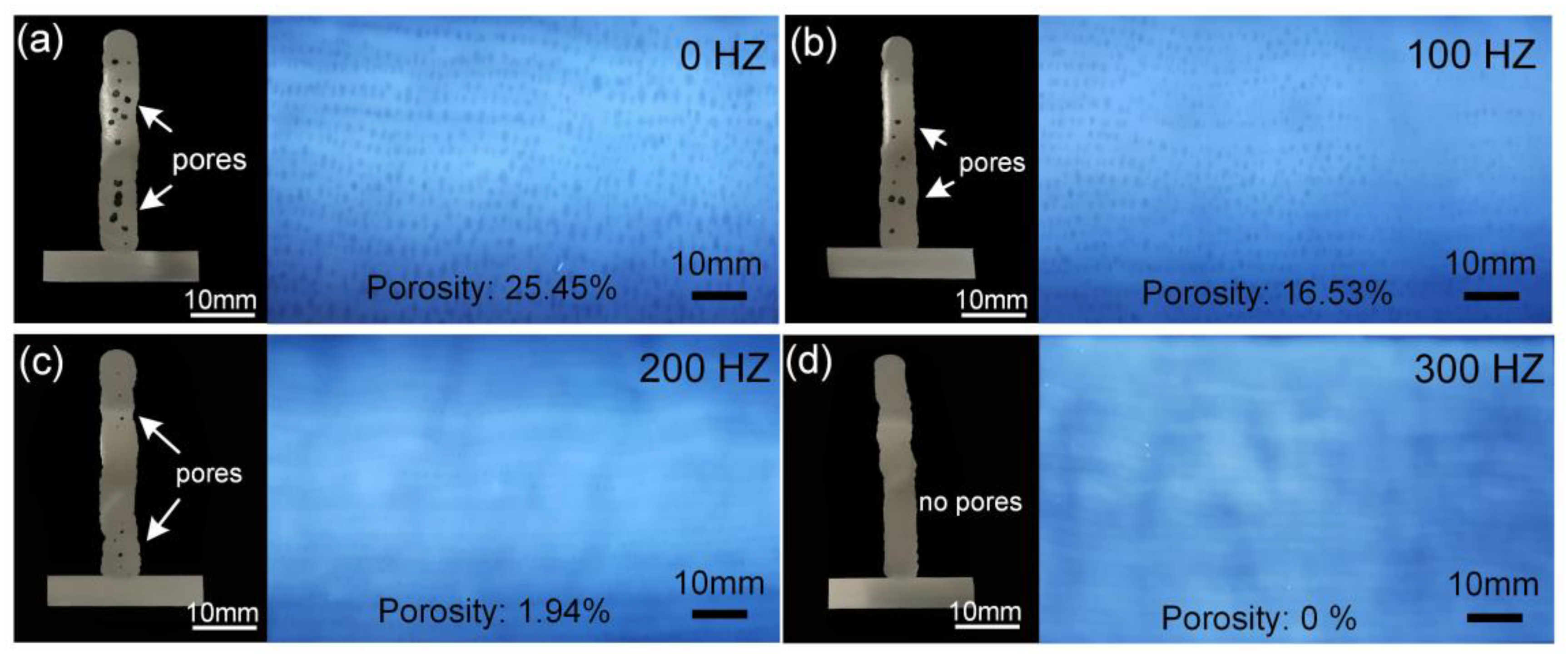
The longitudinal cross-section and transverse X-ray NDT of the thin-walled components are presented in Figure 4. By observing the longitudinal cross-section, it can be found that as the oscillation frequency increases from 0 Hz to 300 Hz, the size and number of pores decrease significantly. By comparing the NDT results, as shown in Figure 4a, it is observed that a large number of chain-like pores are uniformly and densely distributed in each deposited layer of the component without beam oscillation. As shown in Figure 4d, when the oscillation frequency is 300 Hz, there are no pores found in either the cross-section or the NDT results.
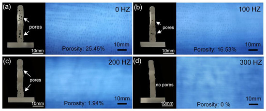
Figure 4.
The longitudinal cross-section and the transverse X-ray NDT results of the components. (a) 0 Hz; (b) 100 Hz; (c) 200 Hz; (d) 300 Hz.
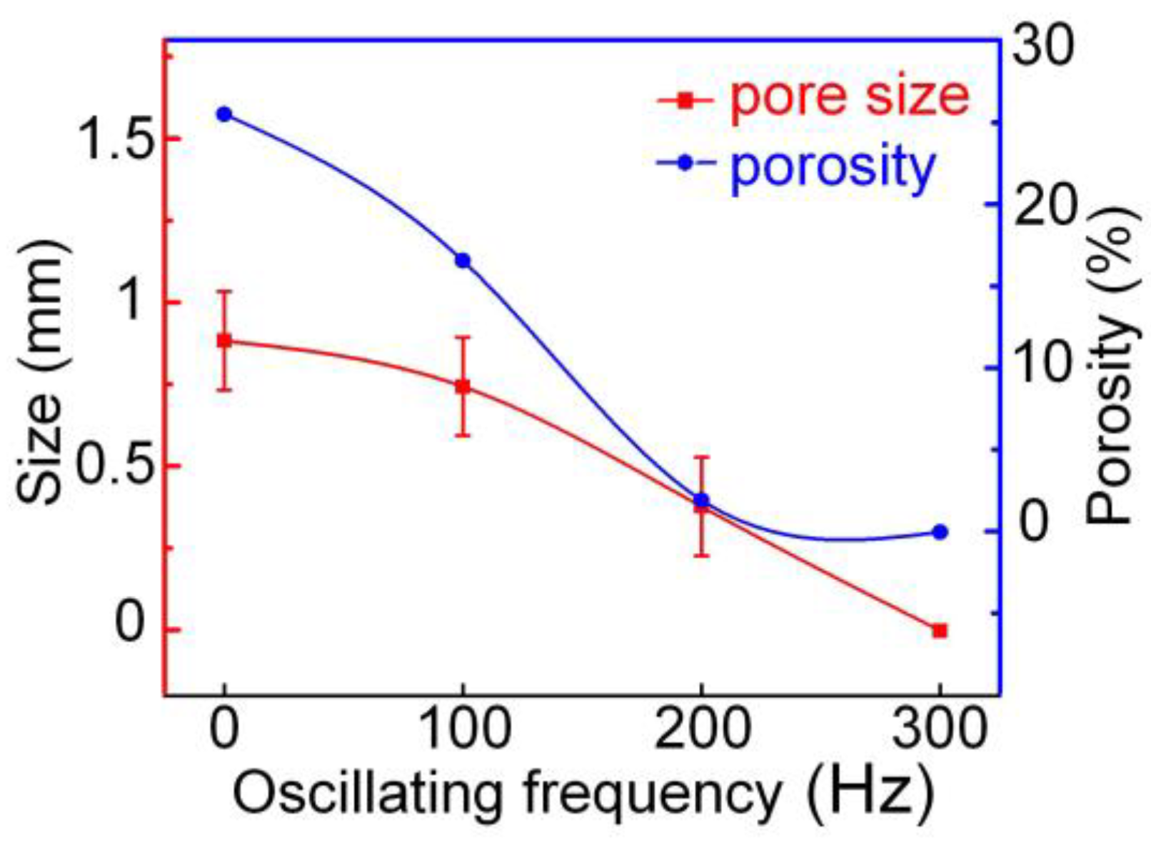
The average pore size and porosity of the thin-walled components are calculated in Figure 5. It can be found that there is a significant negative correlation between the size and number of pores and the beam oscillation frequency. As the beam oscillation frequency increases from 0 Hz to 300 Hz, the porosity decreases from 25.45% to 0%, and the average size decreases from 1.8 mm to 0 mm. The mechanism by which laser oscillation can reduce porosity is discussed later.
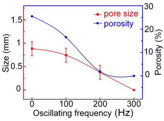
Figure 5.
The relationship curves between pore size and porosity and oscillation frequency.
3.3. Microstructural Analysis
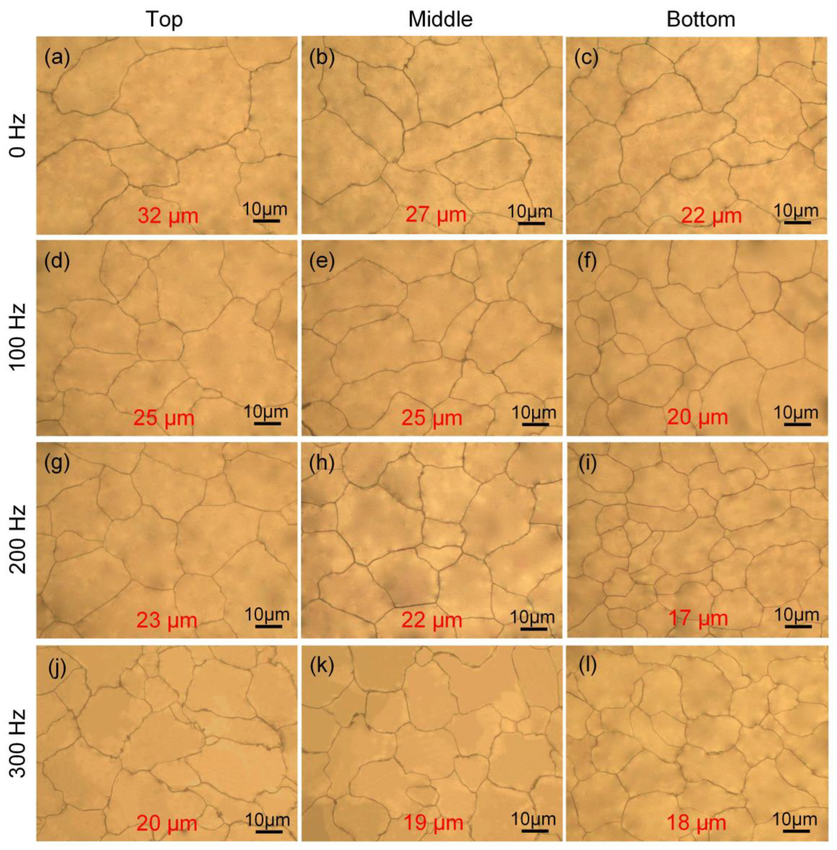
The optical microscopy images of the thin-walled components are given in Figure 6, and the average grain size is calculated. On the one hand, when the oscillation frequency is the same, it can be seen that the grain size gradually increases from the bottom to the top. The main reason is that as the deposition height rises, the heat dissipation conditions become worse, heat accumulates in the component, and the temperature gradient at the top is smaller, which is favorable to grain growth. On the other hand, when the sample position is the same, the grain size is negatively correlated with the oscillation frequency. For example, in the middle of the thin-walled component, the average grain size decreases from 27 µm to 19 µm with a 27.89% reduction as the oscillation frequency increases from 0 Hz to 300 Hz. It can be concluded that the increase in frequency helps to reduce the grain size.
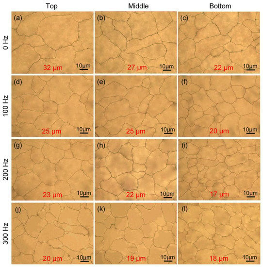
Figure 6.
OM grain size of the AZ31 alloy at various positions from 0 Hz to 300 Hz. (a–c) 0 Hz; (d–f) 100 Hz; (g–i) 200 Hz; (j–l) 300 Hz.
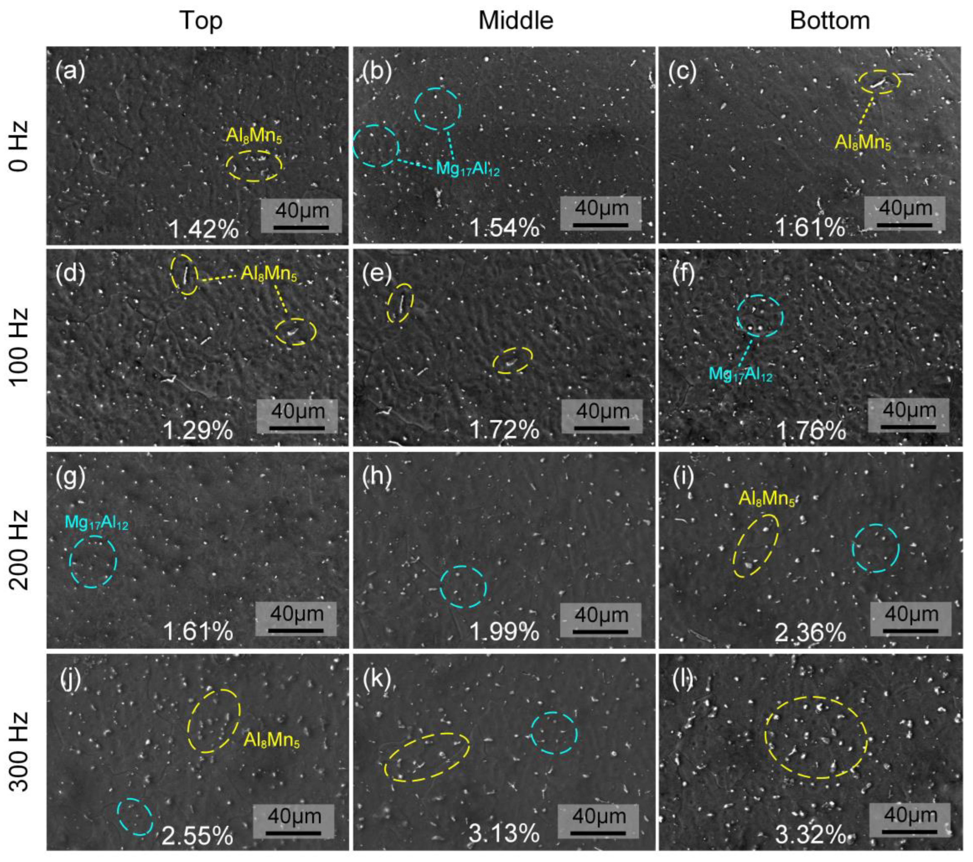
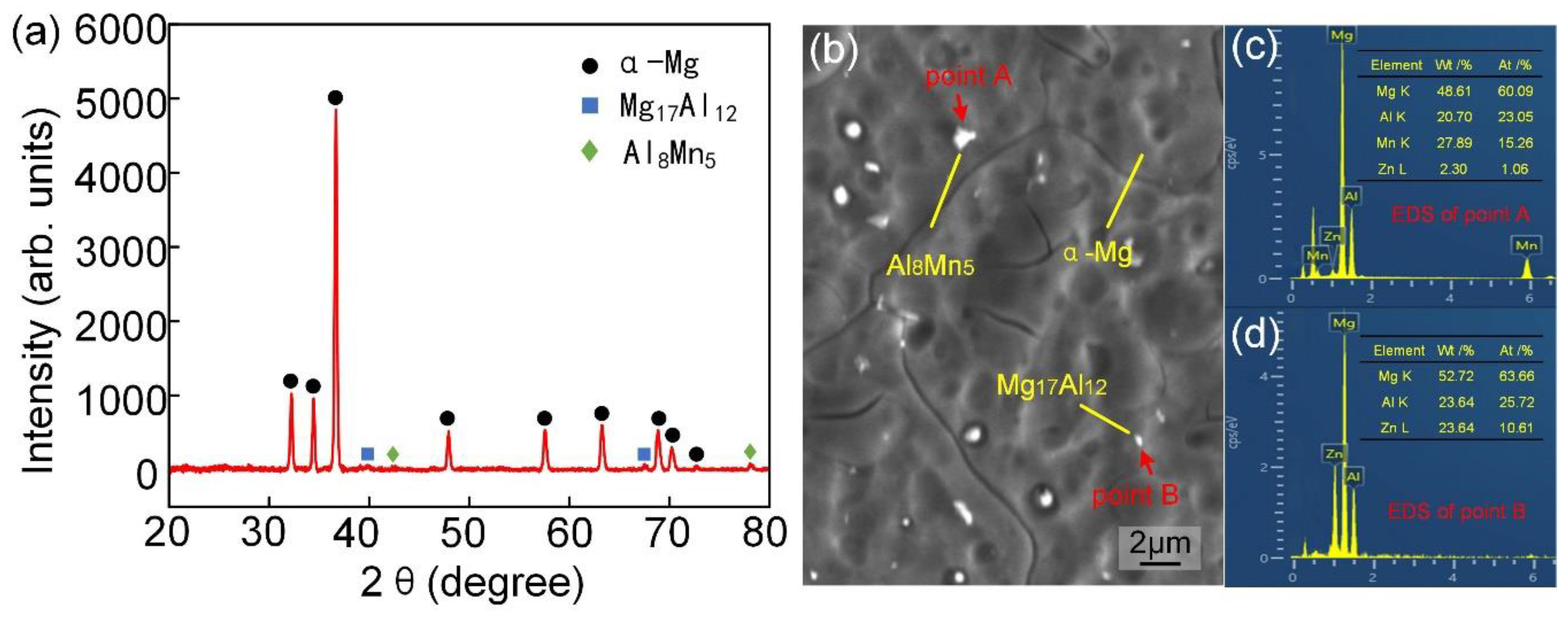
The SEM micrographs in different positions of the thin-walled components from 0 Hz to 300 Hz are given in Figure 7. It can be seen that there are white particles of different sizes distributed on the dark substrate. As shown in Figure 8a, the phase composition was tested and calibrated using XRD, and three main phases, α-Mg, Al8Mn5, and Mg17Al12, were detected. Due to the low content of Al and Mn elements in AZ31 magnesium alloy, the heights of the diffraction peaks of the Al8Mn5 and Mg17Al12 phases were very dwarfed. As shown in Figure 8b–d, the compositions of different microstructures were examined using EDS, and the detailed chemical compositions are shown in Table 3. The dark substrate is composed of α-Mg and a small amount of solidly solved Al atoms. The atomic ratio of Al and Mn elements in the large granular precipitates is about 1.51, which is similar to that of Al8Mn5. The small granular precipitation is the Mg17Al12 phase because no Mn elements are detected, but the Zn content is high for the reason that some Zn atoms can replace Al atoms to form the Mg17(AlZn)12 phase [24]. Therefore, the EDS test results confirm the XRD results. In addition, a large amount of Mg elements was detected in all of the particles, which is because the spot range of EDS is larger than the size of the precipitates. Further, the size difference between the precipitated phases is due to the direct precipitation of the Al8Mn5 phase from the liquid phase, in which Al and Mn atoms can aggregate rapidly, while the Mg17Al12 phase is precipitated from the supersaturated α-Mg solid solution, in which relatively few Al atoms can aggregate.
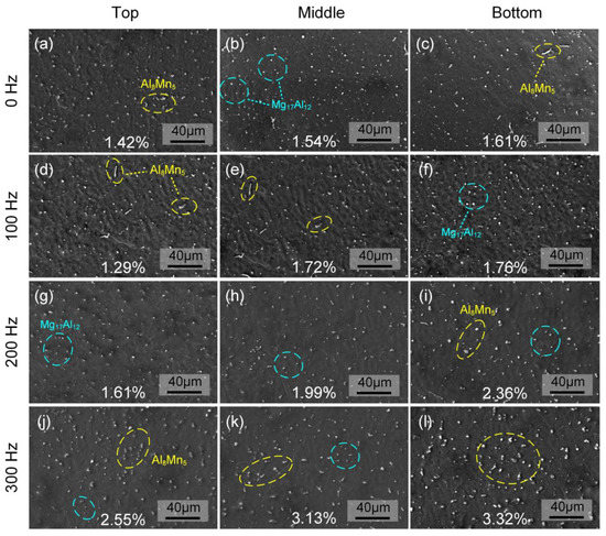
Figure 7.
SEM-SE micrographs of precipitates at various positions from 0 Hz to 300 Hz. (a–c) 0 Hz; (d–f) 100 Hz; (g–i) 200 Hz; (j–l) 300 Hz.
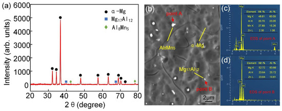
Figure 8.
Chemical composition of thin-walled components. (a) XRD phase spectral lines; (b) Test point location for EDS; (c) Composition spectral line at point A; (d) Composition spectral line at point B.

Table 3.
The EDS results for different microstructures in thin-walled components.
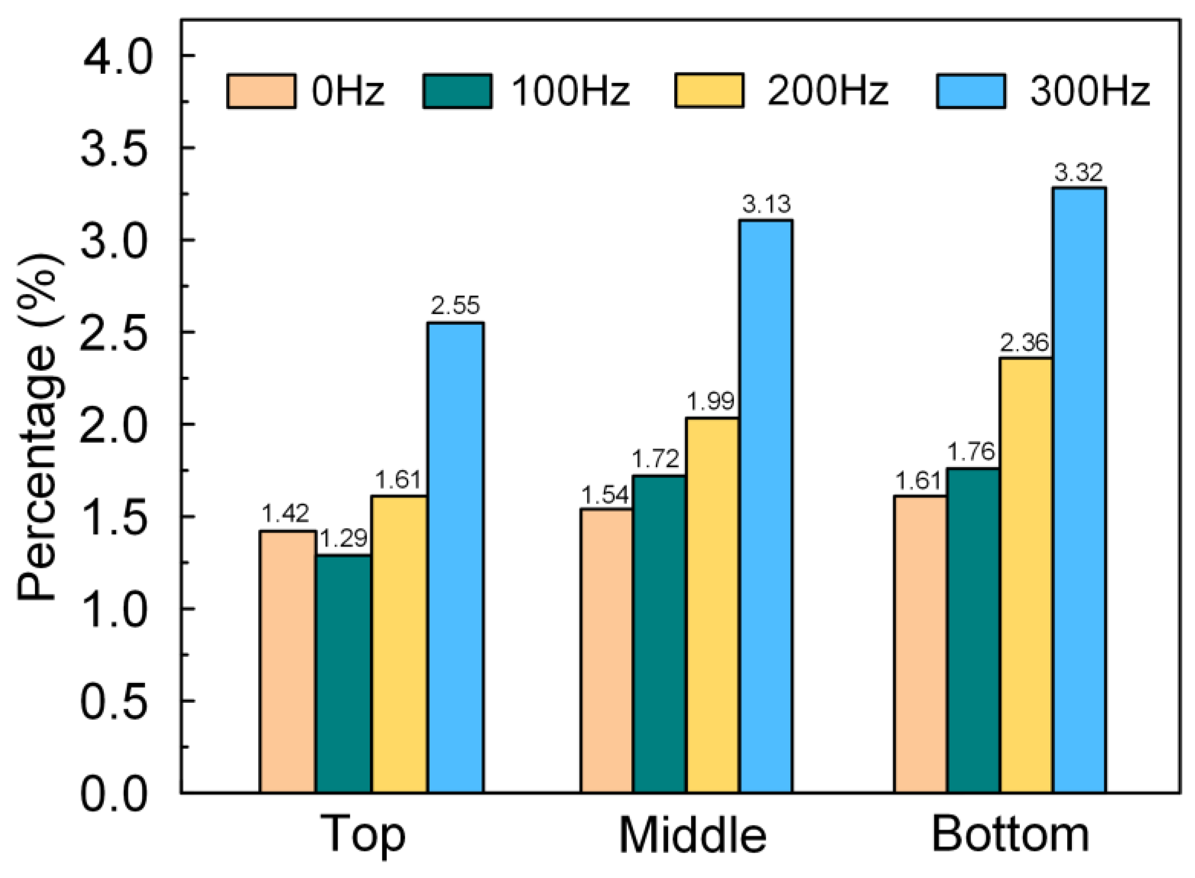
As shown in Figure 9, the granular precipitated phases in Figure 7 were counted. It can be seen that for the same component, the proportion of precipitates gradually decreases from the bottom to the top. Further, at the same position, the proportion of precipitates gradually increases with the increase in frequency. For example, as the frequency increases from 0 Hz to 300 Hz, the precipitate content increases from 1.42–1.61% to 2.55–3.32%.
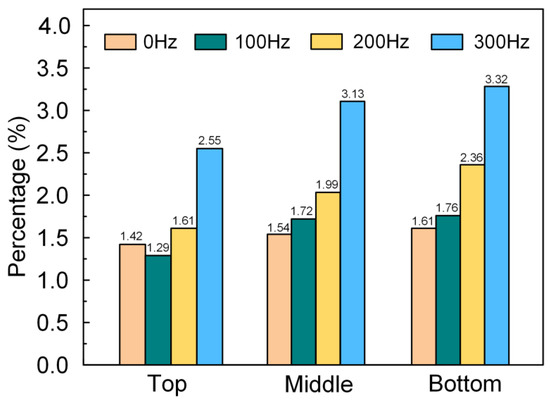
Figure 9.
Columnar statistics of precipitate content at various positions from 0 Hz to 300 Hz.
3.4. Mechanical Properties
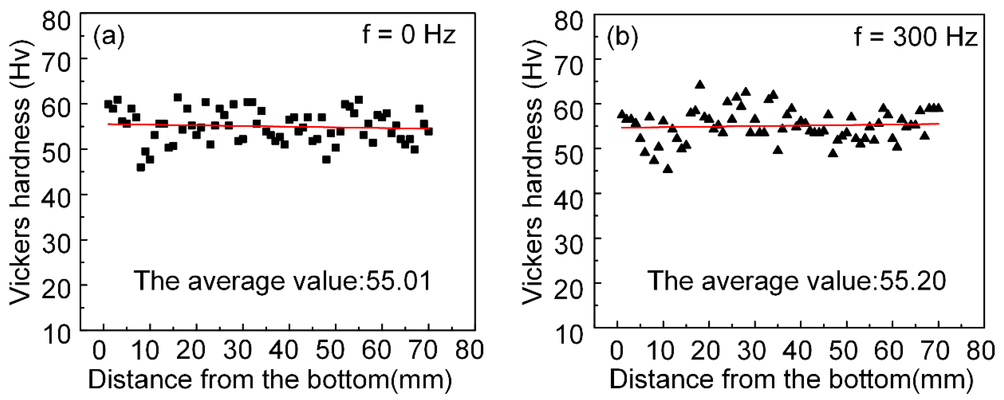
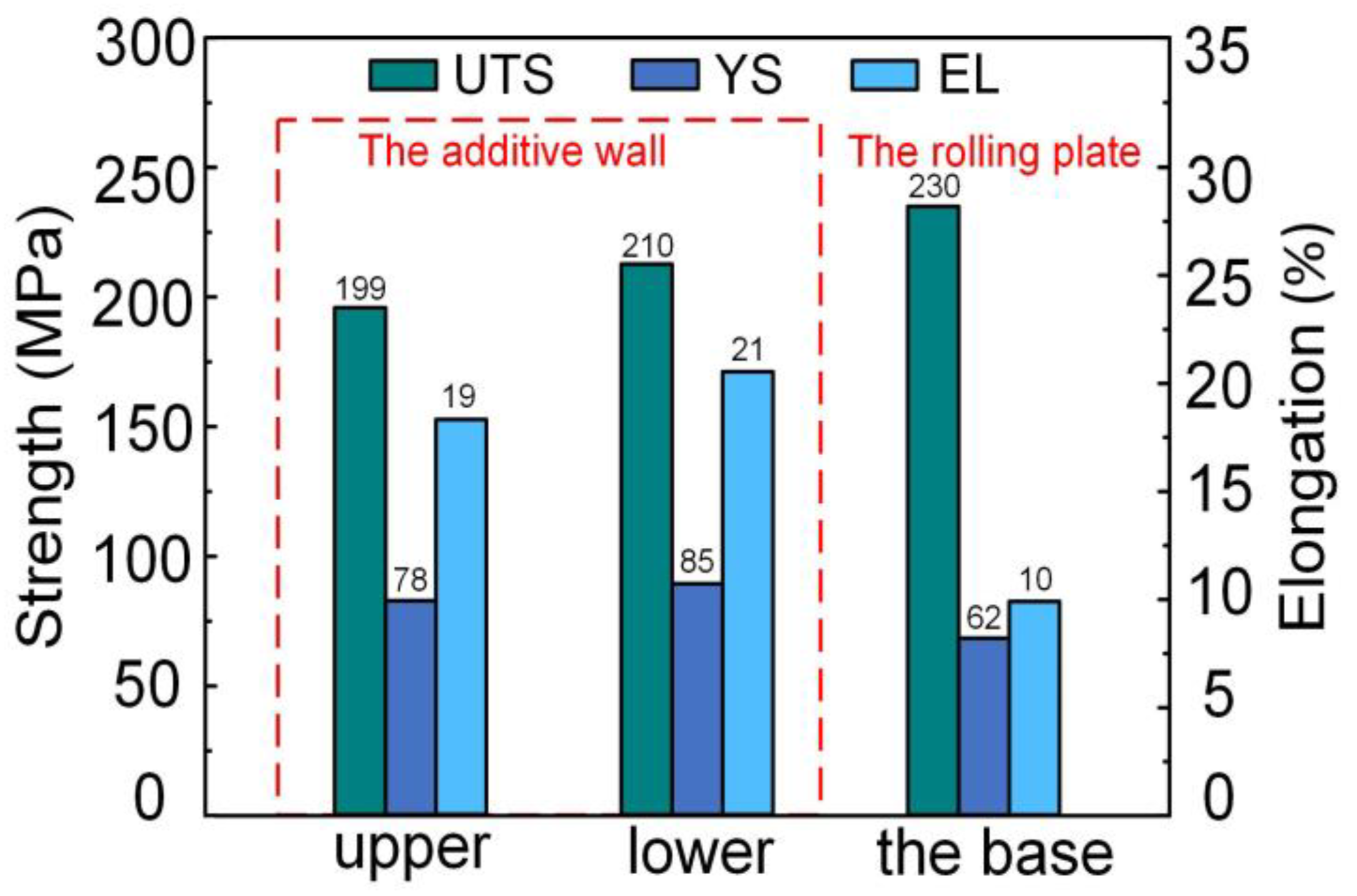
The distribution of hardness values along the height direction of the components is given for 0 Hz and 300 Hz in Figure 10. The average hardness values of the thin-walled components fluctuate in the range of 50–60 Hv without significant changes, which indicates that the beam oscillation does not affect the microhardness. Gao et al. claimed that pores in laser-MIG welded AZ31 magnesium alloy would significantly reduce tensile properties [25]. To avoid the effect of pores, as shown in Figure 11, the mechanical properties of thin-walled component (300 Hz) and the base were compared. The mechanical properties of the lower specimen are slightly higher than those of the upper because the average grain size of the lower specimen is smaller. The ultimate tensile strength (UTS) of the additive component (210 MPa) is about 91.3% of that of the rolled plate (230 MPa), but the yield strength (YS) and elongation (EL) are significantly higher. In addition, compared to the reported CMT arc additive manufacturing of AZ31 magnesium alloy (UTS = 210 MPa, YS = 132 MPa, EL = 10.55%) [15], the UTS is similar, but the EL is significantly improved, and the thin-walled component in this study exhibits better ductility, which may be related to the effective suppression of porosity and grain refinement.
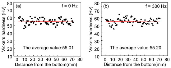
Figure 10.
Distribution of hardness values along the height direction for the component. (a) 0 Hz; (b) 300 Hz.
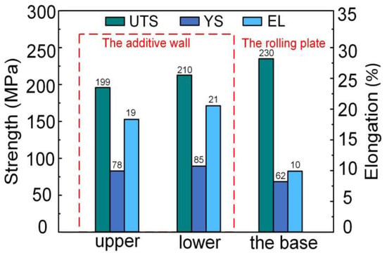
Figure 11.
Comparative histogram of mechanical properties of the additive wall and the rolling plate.
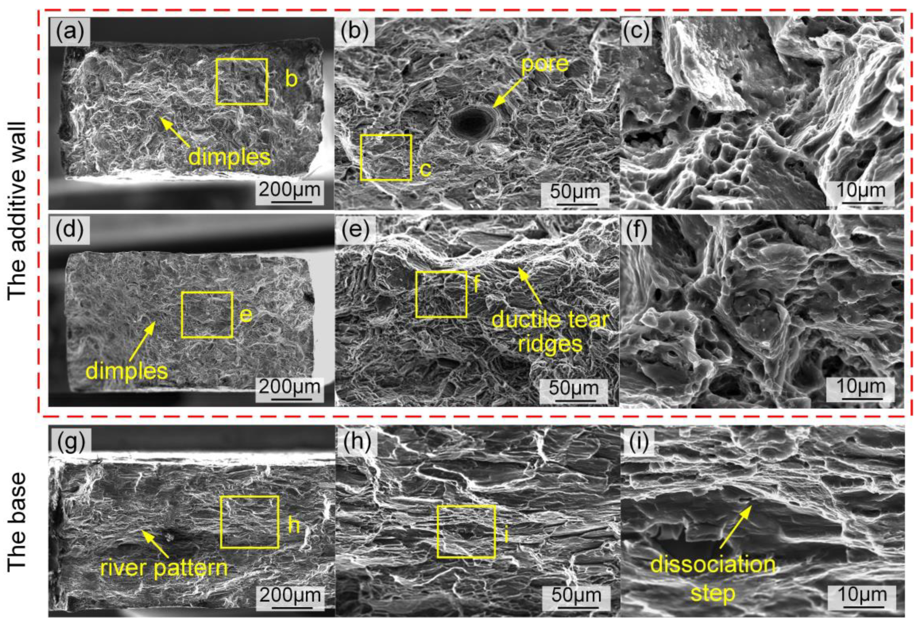
SEM micrographs of the tensile fracture are exhibited in Figure 12. It can be found that there is a significant difference in the fracture characteristics of the additive component and the rolled base. As shown in Figure 12a, the tensile fractures have typical ductile fracture characteristics, with distinct dimples and some steep ductile tearing ridges visible, which are consistent with the excellent ductility they exhibit. However, as shown in Figure 12g–i, the fracture of the rolled plate is a dissociative fracture feature with obvious river patterns and dissociative steps. As shown in Figure 12b, a micro-pore is observed in the fracture, which may be the reason why the upper tensile strength is less than the lower. The tearing ridges present a feature of ductile-brittle hybrid fracture, including dimples and a quasi-cleavage layer (Figure 12c). Further, the pit was found in the tensile fracture of the lower specimen (Figure 11f), which may be related to the escape of the precipitated phase.
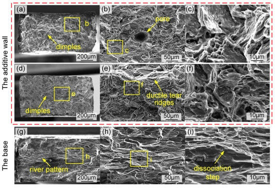
Figure 12.
SEM-SE fracture surface morphology. (a–c) the upper part of the additive wall; (d–f) the lower part of the additive wall; (g–i) the base.
The fracture morphology indicated that the AZ31 magnesium alloy component manufactured using the laser-arc hybrid process has relatively excellent mechanical properties after eliminating porosity defects. Laser oscillation improves the ductility of the component significantly; however, the small number of micropore defects and the escape behavior of the precipitated phase may inhibit the further improvement of mechanical properties.
4. Discussion
4.1. Mechanism of Hump Inhibition Using Beam Oscillation
According to the experimental results, it can be found that beam oscillation can eliminate defects such as lack of fusion, height difference, and wavy hump in the thin-walled components. Among them, unfused and height difference defects are formed because of the uneven heat accumulation at the head and tail of the components. During the deposition process, the gradual accumulation of heat and the uneven dissipation of heat at the head and tail positions lead to the formation of height differences. However, as the oscillation frequency increases, the height difference in the component gradually changes toward a hump defect. Beam oscillation can reduce the temperature gradient and decrease the local solidification rate [26] so that the melt pool at different locations can spread outward evenly. Due to better spreading of the melt pool, unfused defects are removed, and the height difference shifts toward the hump.
The formation and suppression of the hump are related to the flow state of the melt pool changed by the oscillating behavior. Further, the flow state can be characterized by a dimensionless Reynolds number Re [27] computed with Equation (3) as follows:
where ρ is the density of the melt pool, μ is the viscosity of the melt pool, f is the oscillating frequency, and r is the oscillating radius. For the magnesium alloy melt pool, the density ρ is 1.59 g/cm3, and the viscosity μ is 1.2 × 10⁻³ Pa·s [28]. The stirring theory indicates that the laminar flow shifts to turbulent flow in the molten pool when Re is higher than 103. In this experiment, the oscillating behavior could produce a stable stirred laminar flow in the molten pool (shown by the blue arrows in Figure 13) because the calculated Re = 143 is much smaller than the limit of turbulence generation.

Figure 13.
Schematic diagram of hump formation during deposition.
Therefore, the mechanism of beam oscillation to inhibit hump defects is shown in Figure 13. First, the liquid metal in the molten pool is pushed to the tail by the arc pressure and then reversed to form a reflux (shown by the red arrow in Figure 13) [29]. Nguyen et al. found that the liquid metal could build up and solidify at the tail of the melt pool to form a hump when the reflux was hindered [30], and it can be inferred that the wavy hump in this study may be related to the hindered reflux of the liquid metal. As shown in Figure 13, the effect of the laser’s oscillating frequency on the reflux of liquid metal is analyzed. As shown in Figure 13a, the thin-wall component has no hump defects when the laser does not oscillate because there is no stirred laminar flow, and the reflux of liquid metal is smooth in the molten pool. As shown in Figure 13b, the stirred laminar flow is transported backward in the same direction as the liquid metal flow and in the opposite direction of the reflux when the laser begins to oscillate so that the oscillating behavior enhances the liquid metal flow and also hinders its reflux, which leads to the formation of a hump In the thin-wall component. As shown in Figure 13c, when the frequency increases to 300 Hz, the liquid metal flow is so powerful that its reflux will be hardly hindered from flowing smoothly, and therefore, there were no wavy humps formed in the thin-wall components at 300 Hz.
In conclusion, at a lower frequency, the stirred melt flow generated using the oscillating laser in the melt pool hinders the reflow, thus forming a hump defect. However, when the frequency is increased to 300 Hz, the stirred melt flow in the melt pool is enhanced, which, in turn, promotes reflow, thus suppressing the hump. Beam oscillation enables the regulation of the melt flow in the melt pool, which affects the macroscopic morphology of the deposited layer. So, at a high oscillation frequency, the layer-by-layer stacking feature is obvious, and the molding accuracy is significantly improved.
4.2. Mechanism of Pore Elimination Using Beam Oscillation
In general, there are two main reasons for the formation of pores in deposited components: (1) hydrogen pores are formed by the absorption of hydrogen by the melt pool; (2) process pores are generated by the collapse of the laser keyhole. The pore morphology in this experiment is large in size, excluding hydrogen pores visible only at the microscopic level. Due to the low viscosity, high fluidity, and fast solidification of liquid magnesium alloy, it is extremely easy for the laser keyhole to collapse and form pores without oscillation of the beam. Process pores are more likely to form in deposited magnesium alloy components.
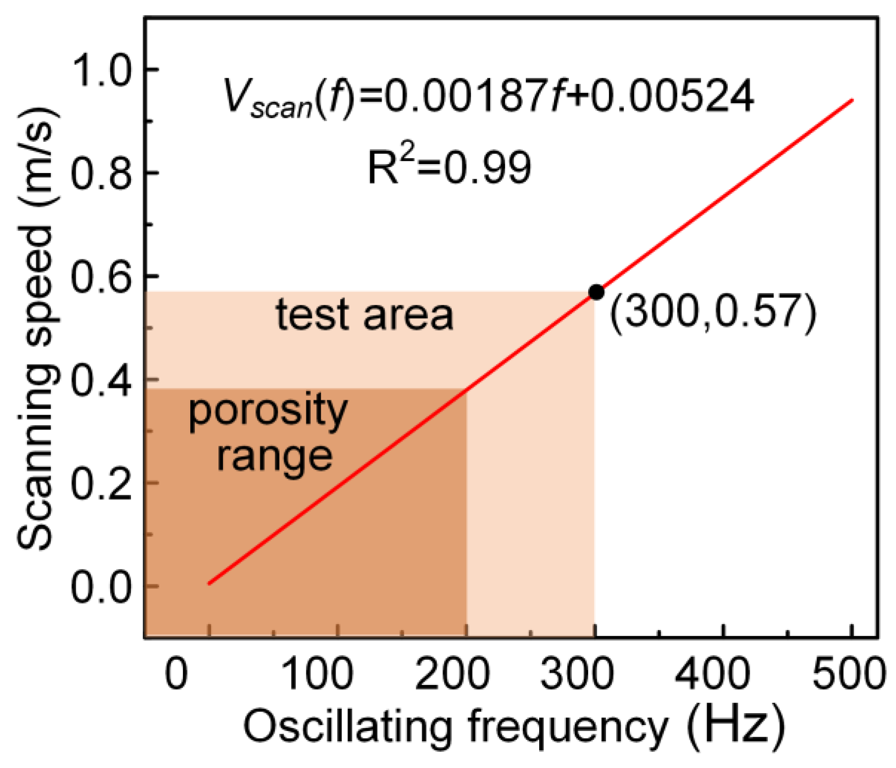
However, it is obvious from the experimental results that the beam oscillation can suppress the pores. There are two main reasons. First, pores formed by the collapse of the keyhole tip are reduced because the high-speed movement of the laser beam helps to stabilize the laser keyhole [31]. According to Equations (4) and (5), the beam scanning speed Vscan can be obtained as a function of the oscillating frequency f. As shown in Figure 14, the curve after the linear fitting of the function shows that the laser beam scanning speed increases with the increase in frequency. The calculation results of this paper show that the components are detected without porosity with the X-ray when the scanning speed of the laser beam is increased to 0.57 m/s(300 Hz). It is similar to the results (0.33 m/s) found by Katayama et al. in high-speed laser welding experiments on aluminum alloys [32]. Second, the scanning effect of the oscillating laser beam, melting the solidified part at the tail of the melt pool, not only releases the solidified porosity [33] but also helps to expand the volume and slow down the solidification rate of the melt pool, so that the bubbles have enough time to escape and reduce the porosity accordingly.
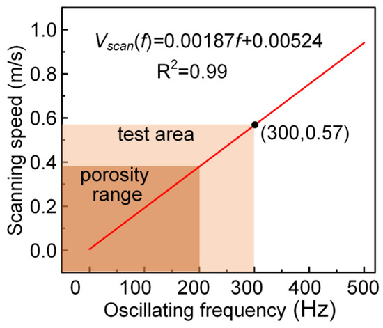
Figure 14.
Relation curve between scanning speed and oscillating frequency.
Furthermore, the stirred laminar flow generated with the beam oscillation can promote the escape of bubbles. When the beam is not oscillating, the bubbles formed by the collapse of the laser keyhole are very easily carried into the solidification front due to the temperature gradient melt flow. It follows that the pores in the component are easily affected by the state of the melt flow in the melt pool. According to the calculation of the Reynolds number in Section 4.1, the flow state in the melt pool is dominated by the high-speed stirred laminar flow. Therefore, as the oscillation frequency increases, the bubbles accelerate with the stirred laminar flow and escape from the melt pool faster. Meanwhile, the shearing effect of the stirred laminar flow will break the bubbles, thus reducing the size of the pores.
4.3. Mechanisms of Microstructure Evolution Using Beam Oscillation
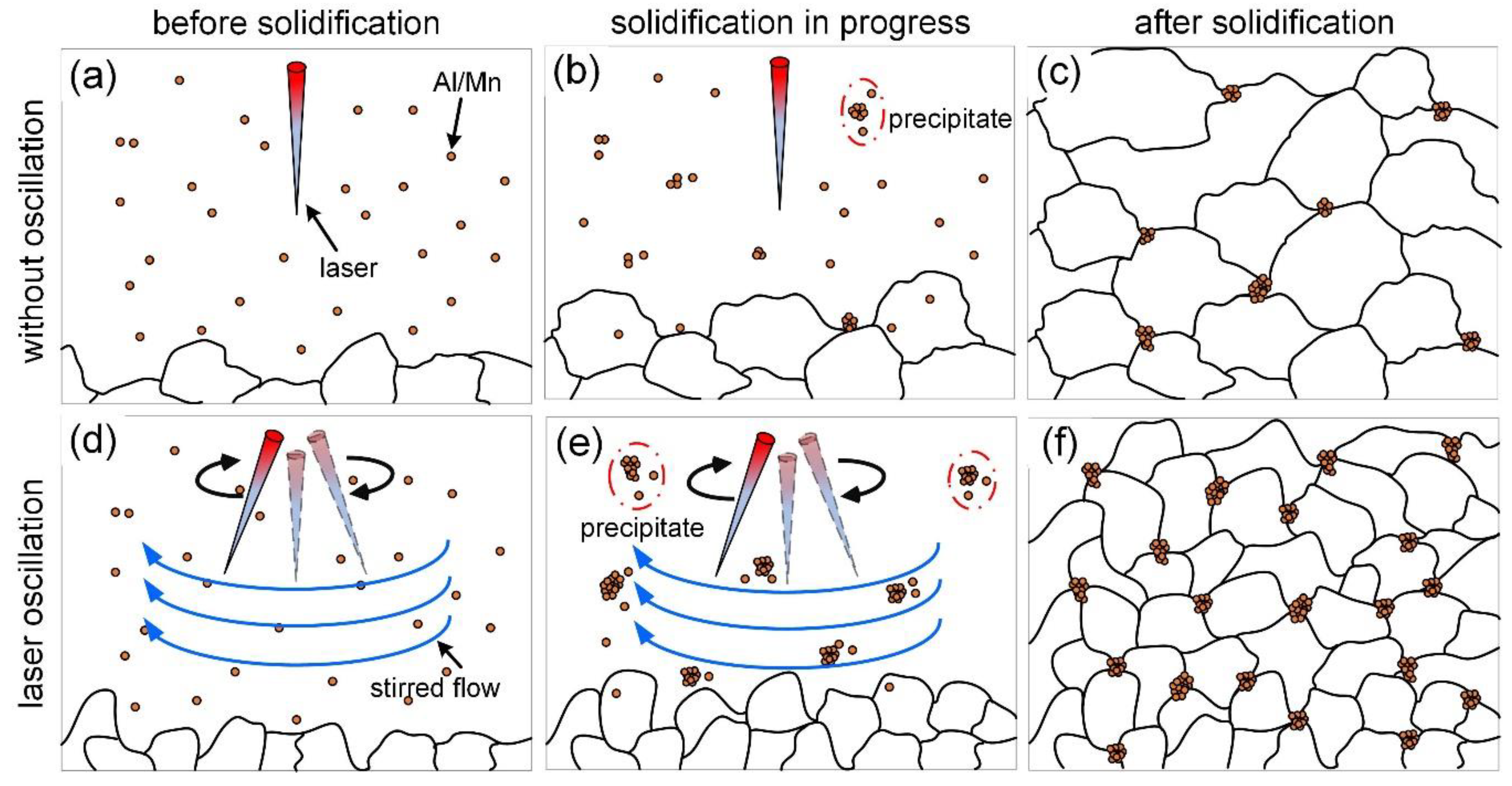
The stirring effect of beam oscillation on the molten pool is the main reason for the grain refinement, which has been studied in detail in oscillating laser welding [33] and oscillating laser cladding [34]. The fast and periodic motion of the oscillation beam generates an oscillatory shear force on the melt pool. Further, the oscillatory shear force is increased sharply as the oscillation frequency increases, driving the melt to form vortices along the oscillation trajectory. Under the effect of the rotating vortex, the initial solidified grain structure is disrupted to provide more nucleation sites for subsequent grain growth, resulting in grain refinement [35]. Therefore, the higher the oscillation frequency, the better the grain refinement effect.
In addition, according to the experimental results, the precipitated phases in the thin-walled components are Al8Mn5 and Mg17Al12, the ratio of which is affected by the Al/Mn atomic content. From the above discussion, it is clear that the stirring effect of the oscillating laser on the melt pool disrupts the crystal structure of the initial solidification to produce more nucleation sites. The nucleation sites increase with the growth of oscillation frequency, making the Al/Mn atoms easier to crystallize and, thus, improving the precipitated phase content. Meanwhile, the precipitated phase produces collision and polymerization to increase the size as a result of the accelerated flow rate of the melt pool. Further, part of the precipitated phase will be re-dissolved and diffused due to the accumulation of heat at the middle and top so that the solidified content is slightly lower.
Therefore, as shown in Figure 15, the mechanism of reducing the grain size and increasing the proportion of the precipitated phase using an oscillating laser can be summarized as follows.
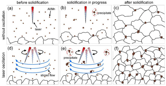
Figure 15.
Schematic diagram of microstructure evolution induced using oscillating laser. (a–c) without oscillation; (d–f) laser oscillation.
When the laser does not oscillate, there is no stirring melt flow in the melt pool, and grain growth and precipitation phase precipitation are only influenced by the temperature gradient melt flow. The probability of collision and aggregation of Al/Mn atoms is reduced, and most of them are diffusely distributed in the α-Al matrix without forming precipitation phases. Eventually, after melt pool solidification, coarse-sized grains, as well as a low percentage of precipitated phases, are obtained in the components.
When the beam oscillates, the stirred melt flow generated with the oscillating laser breaks up the grains and accelerates the melt flow. The Al/Mn atoms in the fast-moving melt flow have a higher probability of colliding and coalescing together to form precipitation phases. Because these precipitation phases are precipitated from the liquid phase, they are also able to provide nucleation sites for grain growth. Eventually, after melt pool solidification, the components produced with beam oscillation have refined grains and more precipitated phases.
5. Conclusions
To improve the macroscopic morphology and reduce the defects of Mg alloy additive components, this paper first carried out the oscillating laser-arc hybrid additive manufacturing (O-LHAM) of AZ31 Mg alloy. It focused on the effect of an oscillating laser on process characteristics such as macroscopic morphology, porosity defects, microstructure, and mechanical properties. The main conclusions obtained are as follows.
(1) The thin-walled components of Mg alloy with good macroscopic morphology and excellent performance could be obtained using the O-LHAM process. Increasing the oscillating frequency helped to suppress the lack of fusion, height difference, and humps because the spreading of the melt pool and the regulation of the reflux of liquid metal were promoted.
(2) As the oscillation frequency increased from 0 Hz to 300 Hz, the porosity decreased from 24.45% to 0. The reason for this was that the high-speed movement of the beam could stabilize the laser keyhole, and second, the oscillating effect of the oscillating behavior could melt the solidified pores.
(3) Increasing the oscillating frequency was beneficial for reducing the average grain size and promoting the precipitation of the Al8Mn5 and Mg17Al12 phases. Compared to the case without oscillation, the average grain size range at 300 Hz decreased from 22–32 μm to 18–20 μm, while the precipitation percentage increased from 1.42–1.61% to 2.55–3.32%. This was because the stirring effect of the oscillating laser was enhanced with increasing frequency.
(4) For the component without pores, the ultimate tensile strength was 205 MPa, slightly less than the base, but the elongation was 20.7%, twice that of the base. The tensile fractures presented ductile fracture characteristics, consisting mainly of dimples and some steep ductile tearing ridges. Laser oscillation had almost no effect on the hardness values of thin-wall components but could significantly improve their ductility.
Author Contributions
Conceptualization, M.G. (Ming Gao); methodology, L.C. and L.J.; writing—original draft preparation, L.C.; validation, M.G. (Mengcheng Gong); formal analysis, L.C.; investigation, L.J. and S.Z.; supervision, M.G. (Ming Gao); funding acquisition, M.G. (Ming Gao). All authors have read and agreed to the published version of the manuscript.
Funding
This research was financially supported by the National Natural Science Foundation of China (Grant No: 52275335 and Grant No: 52205465).
Institutional Review Board Statement
Not applicable.
Informed Consent Statement
Not applicable.
Data Availability Statement
The data presented in this study are available upon request from the corresponding author.
Conflicts of Interest
The authors declare no conflict of interest.
References
- Sahoo, K.; Poddar, P. Studies on Magnesium Alloys–Properties and Potential for Automotive and Aerospace Applications. In Proceedings of the Transaction of 65th Indian foundry Congress, Kolkata, India, 3–5 February 2017; Volume 2017, pp. 151–156. [Google Scholar]
- Mordike, B.; Ebert, T. Magnesium: Properties—Applications—Potential. Mater. Sci. Eng. A 2001, 302, 37–45. [Google Scholar] [CrossRef]
- Blawert, C.; Hort, N.; Kainer, K. Automotive applications of magnesium and its alloys. Trans. Indian Inst. Met. 2004, 57, 397–408. [Google Scholar]
- Mughal, M.; Fawad, H.; Mufti, R. Three-dimensional finite-element modelling of deformation in weld-based rapid prototyping. Proc. Inst. Mech. Eng. Part C 2006, 220, 875–885. [Google Scholar] [CrossRef]
- Ding, D.; Pan, Z.; Cuiuri, D.; Li, H. Wire-feed additive manufacturing of metal components: Technologies, developments and future interests. Int. J. Adv. Manuf. Technol. 2015, 81, 465–481. [Google Scholar] [CrossRef]
- Luo, A.A. Materials comparison and potential applications of magnesium in automobiles. In Essential Readings in Magnesium Technology; Springer: Berlin/Heidelberg, Germany, 2016; pp. 25–34. [Google Scholar]
- Clow, B.B. Magnesium industry overview. Adv. Mater. Process. 1996, 150, 33–35. [Google Scholar]
- Easton, M.; Beer, A.; Barnett, M.; Davies, C.; Dunlop, G.; Durandet, Y.; Blacket, S.; Hilditch, T.; Beggs, P. Magnesium alloy applications in automotive structures. Jom 2008, 60, 57. [Google Scholar] [CrossRef]
- Hu, D.; Wang, Y.; Zhang, D.; Hao, L.; Jiang, J.; Li, Z.; Chen, Y. Experimental investigation on selective laser melting of bulk net-shape pure magnesium. Mater. Manuf. Process. 2015, 30, 1298–1304. [Google Scholar] [CrossRef]
- Wei, K.; Gao, M.; Wang, Z.; Zeng, X. Effect of energy input on formability, microstructure and mechanical properties of selective laser melted AZ91D magnesium alloy. Mater. Sci. Eng. A 2014, 611, 212–222. [Google Scholar] [CrossRef]
- Wei, K.; Wang, Z.; Zeng, X. Influence of element vaporization on formability, composition, microstructure, and mechanical performance of the selective laser melted Mg–Zn–Zr components. Mater. Lett. 2015, 156, 187–190. [Google Scholar] [CrossRef]
- Knezović, N.; Topić, A. Wire and arc additive manufacturing (WAAM)—A new advance in manufacturing. In International Conference “New Technologies, Development and Applications”; Springer: Berlin/Heidelberg, Germany, 2018; pp. 65–71. [Google Scholar]
- Guo, J.; Zhou, Y.; Liu, C.; Wu, Q.; Chen, X.; Lu, J. Wire arc additive manufacturing of az31 magnesium alloy: Grain refinement by adjusting pulse frequency. Materials 2016, 9, 823. [Google Scholar] [CrossRef]
- Takagi, H.; Sasahara, H.; Abe, T.; Sannomiya, H.; Nishiyama, S.; Ohta, S.; Nakamura, K. Material-property evaluation of magnesium alloys fabricated using wire-and-arc-based additive manufacturing. Addit. Manuf. 2018, 24, 498–507. [Google Scholar] [CrossRef]
- Yang, X.; Liu, J.; Wang, Z.; Lin, X.; Liu, F.; Huang, W.; Liang, E. Microstructure and mechanical properties of wire and arc additive manufactured AZ31 magnesium alloy using cold metal transfer process. Mater. Sci. Eng. A 2020, 774, 138942. [Google Scholar] [CrossRef]
- Gao, M.; Zeng, X.; Yan, J.; Hu, Q. Microstructure characteristics of laser–MIG hybrid welded mild steel. Appl. Surf. Sci. 2008, 254, 5715–5721. [Google Scholar] [CrossRef]
- Qian, Y.P.; Huang, J.H.; Zhang, H.O.; Wang, G.L. Direct rapid high-temperature alloy prototyping by hybrid plasma-laser technology. J. Mater. Process. Technol. 2008, 208, 99–104. [Google Scholar] [CrossRef]
- Zhang, Z.; Sun, C.; Xu, X.; Liu, L. Surface quality and forming characteristics of thin-wall aluminium alloy parts manufactured by laser assisted MIG arc additive manufacturing. Int. J. Lightweight Mater. Manuf. 2018, 1, 89–95. [Google Scholar] [CrossRef]
- Zhang, L.J.; Ning, J.; Zhang, X.J.; Zhang, G.F.; Zhang, J.X. Single pass hybrid laser–MIG welding of 4-mm thick copper without preheating. Mater. Des. 2015, 74, 1–18. [Google Scholar] [CrossRef]
- Seto, N.; Katayama, S.; Matsunawa, A. Porosity formation mechanism and suppression procedure in laser welding of aluminium alloys. Weld. Int. 2001, 15, 191–202. [Google Scholar] [CrossRef]
- Gong, M.; Meng, Y.; Zhang, S.; Zhang, Y.; Zeng, X.; Gao, M. Laser-arc hybrid additive manufacturing of stainless steel with beam oscillation. Addit. Manuf. 2020, 33, 101180. [Google Scholar] [CrossRef]
- Lorenzin, G.; Rutili, G. The innovative use of low heat input in welding: Experiences on ‘cladding’and brazing using the CMT process. Weld. Int. 2009, 23, 622–632. [Google Scholar] [CrossRef]
- Hu, S.; Zhang, H.; Wang, Z.; Liang, Y.; Liu, Y. The arc characteristics of cold metal transfer welding with AZ31 magnesium alloy wire. J. Manuf. Process. 2016, 24, 298–306. [Google Scholar] [CrossRef]
- Tu, Y.F.; Chen, J.Y.; Zhang, B.P.; Li, P.X.; Suzuki, H.G. Phases and microstructure of as-cast AZ 31 magnesium alloy. Foundry 2006, 55, 509–512. [Google Scholar]
- Gao, M.; Zeng, X.Y.; Tan, B.; Feng, J.C. Study of laser MIG hybrid welded AZ31 magnesium alloy. Sci. Technol. Weld. Join. 2013, 14, 274–281. [Google Scholar] [CrossRef]
- Hagenlocher, C.; Sommer, M.; Fetzer, F.; Weber, R.; Graf, T. Optimization of the solidification conditions by means of beam oscillation during laser beam welding of aluminum. Mater. Des. 2018, 160, 1178–1185. [Google Scholar] [CrossRef]
- Sinnott, R.K.; Coulson, J.M.; Richardson, J.F. Chemical Engineering Design; Elsevier Butter-worth-Heinemann: Oxford, UK, 2005; Volume 6, p. 4. [Google Scholar]
- Culpin, M. The viscosity of liquid magnesium and liquid calcium. Proc. Phys. Soc. Sect. B 1957, 70, 1079. [Google Scholar] [CrossRef]
- Nguyen, T.C.; Weckman, D.C.; Johnson, D.A. Predicting onset of high speed gas metal arc weld bead defects using dimensional analysis techniques. Sci. Technol. Weld. Join. 2007, 12, 634–648. [Google Scholar] [CrossRef]
- Nguyen, T.C.; Weckman, D.C.; Johnson, D.A.; Kerr, H.W. The humping phenomenon during high speed gas metal arc welding. Sci. Technol. Weld. Join. 2013, 10, 447–459. [Google Scholar] [CrossRef]
- Katayama, S.; Nagayama, H.; Mizutani, M.; Kawahito, Y. Fibre laser welding of aluminium alloy. Weld. Int. 2009, 23, 744–752. [Google Scholar] [CrossRef]
- Fetzer, F.; Sommer, M.; Weber, R.; Weberpals, J.P.; Graf, T. Reduction of pores by means of laser beam oscillation during remote welding of AlMgSi. Opt. Lasers Eng. 2018, 108, 68–77. [Google Scholar] [CrossRef]
- Wang, L.; Gao, M.; Zhang, C.; Zeng, X. Effect of beam oscillating pattern on weld characterization of laser welding of AA6061-T6 aluminum alloy. Mater. Des. 2016, 108, 707–717. [Google Scholar] [CrossRef]
- Cen, L.; Du, W.; Gong, M.; Lu, Y.; Zhang, C.; Gao, M. Effect of high-frequency beam oscillation on microstructures and cracks in laser cladding of Al-Cu-Mg alloys. Surf. Coat. Technol. 2022, 447, 128852. [Google Scholar] [CrossRef]
- Wang, F.; Williams, S.; Rush, M. Morphology investigation on direct current pulsed gas tungsten arc welded additive layer manufactured Ti6Al4V alloy. Int. J. Adv. Manuf. Technol. 2011, 57, 597–603. [Google Scholar] [CrossRef]
Disclaimer/Publisher’s Note: The statements, opinions and data contained in all publications are solely those of the individual author(s) and contributor(s) and not of MDPI and/or the editor(s). MDPI and/or the editor(s) disclaim responsibility for any injury to people or property resulting from any ideas, methods, instructions or products referred to in the content. |
© 2023 by the authors. Licensee MDPI, Basel, Switzerland. This article is an open access article distributed under the terms and conditions of the Creative Commons Attribution (CC BY) license (https://creativecommons.org/licenses/by/4.0/).

