1. Introduction
Escalation of rapidly progressive heart failures inflicts considerable morbidity and mortality [
1]. As a result, this further leads to increased consumption of significant healthcare resources and affects quality of life. Left ventricular assist devices (LVAD) such as intra-aortic balloon pump, IMPELLA
® [
2], VA ECMO (e.g., [
3,
4]), POLVAD [
5], Levitronix [
6], CentriMag™ [
7], TandemHeart™ [
8], HeartMate 3™ [
7], HeartWare™ [
9], are used for advanced heart failure, when advanced conservative treatment is not sufficient to prevent further deterioration of the patients’ condition. There are two treatments for such disease, namely heart transplantation and artificial heart pumps. Heart transplantation in patients with advanced heart failure is considered the best treatment option [
10] but at the same time can be difficult because of the relatively high costs, lack of donor organs, and the growing number of patients waiting for heart transplantation [
11,
12,
13,
14] as well as organ rejection and mortality rates.
LVAD is an effective therapeutic approach as a bridge to heart transplantation [
15,
16] for patients with end-stage heart failure and are also increasingly being used for destination therapy [
17]. Two main types of LVAD can be distinguish, i.e., pulsatile and continuous flow devices. Until 2009, pulsatile flow pumps were common, whereas since 2010, continuous flow pumps have been used almost exclusively [
18,
19]. One can further distinguish centrifugal and axial blood pumps where the latter is much smaller in comparison to the former [
20]. As axial blood pumps require much higher angular velocities to increase outlet pressure, this can lead to blood damage, i.e., thrombosis [
21] and haemolysis [
22,
23]. What is more, the functioning of most currently available implantable devices is based on the mechanism of continuous blood flow, i.e., delivers a constant pressure, which contributes to the formation of arrhythmias in the heart [
24,
25]. The operation of the proposed innovative assist device is based on the strategy of pulsatile flow that is synchronized with the heart cycle which will avoid the limitations of the methods used so far. Furthermore, with chronic heart failure, residual mitral regurgitation is often present, which translates into pulmonary hypertension in the patient and right ventricular dysfunction. Implantation of available devices is characterised by elevated pulmonary pressures, poorer right ventricular function [
26,
27] and even higher mortality [
28].
Implantation of existing cardiac assist devices requires surgery using median sternotomy or pericardiotomy, which have adverse effects on patients with severe heart failure. There is a need to develop a left ventricular assist system with minimally invasive implantation. Minimally invasive surgery is a minor thoracic trauma that does not impair respiratory process. Instead, it allows early mobilization of the patient and significantly reduces hospitalization time. Moreover, the devices currently available are used to temporarily support the ailing heart, i.e., to support patients during hospitalization and are not intended for outpatient applications. HeartMate 3™ and HeartWare™, however, allow patients returning home, but battery replacement and close monitoring can nevertheless bring some difficulties. Solutions are still being sought that offer the possibility of permanent left ventricular support or replacement in patients with end-stage heart failure associated with mitral regurgitation and pulmonary hypertension, especially when patients are resistant to pharmacological treatment [
12] and cannot undergo extensive cardiac surgery due to their medical condition or other reasons. In this case, mechanical circulatory support is considered a safe and effective treatment strategy for patients with end-stage heart failure [
29,
30,
31].
The main purpose of the paper is to introduce an innovative implantable left ventricular assist device and presents its experimental performance that meets the expected functionality and overcomes the problems of the existing cardiac assist devices.
2. Innovative Assist Device
An innovative device [
32,
33] for supporting the operation of the left ventricle in the form of a flexible balloon is shown in
Figure 1a. The balloon unit is an intracardiac, expandable and contractible working chamber, which is divided into a smaller valve balloon (1) inserted into a valve (3) and a larger ventricular balloon (2) inserted into the left ventricle (5). The working chamber is thus divided into two sub-balloons, created in the patient’s heart by expanding the chamber space by gas and then contracting it. Moreover, both balloons are divided by a narrowing made between the transition of one balloon to the other. Importantly, the design ensures that the balloons expand and contracts according to the normal functioning of the left ventricle, so that in the systolic phase the valve balloon (1) and ventricular balloon (2) are inflated, thereby increasing the stroke volume of the heart. In the diastolic phase, the valve balloon (1) and the ventricular balloon (2) deflate. In this way it is possible to effectively occlude the mitral valve, i.e., assisting or replacing the left ventricle in a permanent manner in patients with end-stage heart failure, accompanied by mitral valve regurgitation and pulmonary hypertension.
Figure 1a also shows the aorta (4) and the left atrium (6) for reference. Because in the laboratory studies a rigid and elastic heart model was used, for avoidance of an influence on rheological conditions, a mechanical valve with known and measurable prosthetic parameters was used. Therefore, the aortic valve is replaced by an artificial mechanical valve and thus is not presented in
Figure 1a.
Moreover, inside the working chamber there is a pneumatic gas supply line to the balloons. Both balloons are inflated and deflated with an inert gas (e.g., helium) during use by means of a suction-discharge device. A single pneumatic line supplying both balloons has been taken into consideration see
Figure 1b. The line has at least two outlets, i.e., inside the valve balloon and furthermore has an additional outlet (or outlets) inside the ventricular balloon allowing inflation and deflation of the ventricular balloon. The correct sequential operation of the balloons is due to the difference in size of the balloons and the appropriately selected outlets (holes), i.e., their position, number and their diameters (
Figure 1b). These parameters were selected during experimental studies, where dozens of different variants were tested, and the balloons’ work was recorded with a high-speed camera and analyzed frame by frame to select the best variant. Other variants are also possible (e.g., two independent supply lines) [
32,
33]. However, the former option proved simpler and better, as it did not require synchronized operation between the pneumatic lines, was lighter and had lower power consumption.
The suction-discharge device reduces and increases the volume of gas-filled balloons in a sequential manner, i.e., first the valve balloon is inflated with gas and then the ventricular balloon is inflated in the systolic phase thus increasing the stroke volume of the heart, while in the diastolic phase the valve and ventricular balloons are deflated. A diagram explaining the principle of operation is shown in
Figure 2.
What is more, a suction-discharge device is connected to the system controlling the mode of supplying balloons in rhythm with the normal functioning of the left ventricle, which is controlled by the control system. This ensures precise control of the start and end of inflation of each balloon so that the ejection of blood into the aorta takes place at the occluded mitral exit in relation to the heart cycle determined on the basis of simultaneous ECG measurements. Importantly, changing the volume of gas, inflating the ventricular balloon in each cycle, provides a precise degree of circulatory support, enabling the regulation of haemodynamic parameters, i.e., regulation of cardiac output by changing the stroke volume. This will permit fully controlled, gradual, physiological load on the heart without increased afterload.
The volume of two balloons can be adjusted to the size of the space to individual chambers of the heart. Furthermore, the device in the folded state with the balloons deflated can be implanted in the heart chamber. After implantation at the target site, the set of balloons takes the final shape. This results in minimally invasive implantation through the aorta and removal when the function of the left ventricle improves without the need for extensive cardiac surgery which is associated with the use of extracorporeal circulation, general anesthesia and endotracheal intubation and therefore with an increased risk of complications.
3. Methods—Experimental Stand
In order to carry out realistic experiments of the performance of the implantable left ventricular assist device, an experimental stand (shown in
Figure 3) was designed. The stand consists of a flexible left heart model which is closed in a transparent cylinder (1). The two balloons are inflated and deflated with gas during use by means of a suction-discharge device. Other most important elements are: (2)—the flow reservoir that replaces the pulmonary veins, (3)—the sensor for measuring pressure in the atrium (High Precision Transmitter ATM.1ST STS Sensor Technik Sirnach), (4)—the sensor for measuring pressure in the aorta, behind the heart model (High Precision Transmitter ATM.1ST STS Sensor Technik Sirnach), (5)—the artificial blood mass flow meter (KROHNE OPTIBATCH 4011 C).
The periodic movement of the suction-discharge device ensures that the balloons expands and contracts according to the normal functioning of the left ventricle. First, the valve balloon effectively occludes the mitral valve. Subsequently, the chamber balloon is filled with gas increasing its volume, therefore pumping a certain amount of artificial blood (glycerol in water mixture) into the aorta through the valve. Moreover, the stand also consists of several tanks (flexible and fixed) to ensure that appropriate operating parameters of the hydraulic system are achieved. The main goal was to provide adequate pressures mainly in the atrium, ventricle and aorta as well as in other parts of the system. What is more, the control system with a PLC ensured the specific frequency operation of suction-discharge device as well as times of balloon inflation and the flexible left heart model.
In order to reproduce heart contractility, a special compression system of the left ventricle model (shown in
Figure 4 and
Figure 5) was designed. This was obtained by using a transparent and hermetic cylinder imposed on a heart model. A closed volume was created in this way, in which it was possible to squeeze the heart model in the planned way through cyclically supplying gas with suitable positive and negative gauge pressure. This provided the additional required flow of artificial blood in the hydraulic circuit. A gas pressure sensor placed near a set of balloons was used in a pneumatic system (i.e., suction-discharge device) together with other sensors, the positions of which are shown in
Figure 4b.
4. Results and Discussion
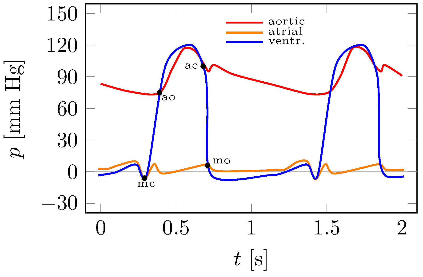
Figure 6 shows an illustrative Wiggers diagram with the characteristic points highlighted, such as the opening and closure of the mitral and aortic valves. On the
x-axis is the time
t, which in this case includes two complete heart cycles, and on the
y-axis are the aortic, atrial and ventricular pressures
p.
Figure 6 provides a reference point for the experimental plots in
Figure 7 and
Figure 8.
Experimental studies were carried out on the experimental stand in
Figure 3 for several hundred different pumping parameters of the so-called artificial blood. These tests involved different versions of the pneumatic line. Parameters such as the density and temperature of the liquid, the frequency of operation of the system (number of balloon inflation and deflation cycles), the gas pressure in the balloon, the gas pressure in the cylinder enclosing the heart model, and the pressure in the hydraulic (blood) system were varied. The hydraulic flows used the work of the balloons in the heart model from
Figure 4 and
Figure 5.
Figure 7a,c and
Figure 8a,c show pressure plots for two adjacent cycles.
Figure 7b,d and
Figure 8b,d show the average pressure values for thirty cycles with superimposed standard deviations in the form of error intervals.
Figure 7 and
Figure 8 shows the two extreme results of the left ventricular assist device performance. Using the control system, the appropriate balloon operation was achieved. First, the valve and ventricular balloons were supplied with gas from the suction-discharge device for half a second, and then the balloons were deflated of gas for another half a second. It follows that the assist device worked at a rate of 60 cycles per minute.
The plots in
Figure 7a correspond to the case where the patient has low blood pressure (hypotension). The aortic pressure took values in the range of approximately 32 to 78 mm Hg. In this case, the average flow rate of a fluid with a density of 1055
was
(
). It is known that with cardiac assist, it is possible to pump fluid (blood) into the hydraulic system when the pressure of the gas in the balloon is higher than the fluid in the left ventricle. This can be seen in
Figure 7a and
Figure 8a. The gas pressure in the ventricular balloon during blood pumping from the the ventricle exceeds the fluid pressure by approximately 90 mm Hg, while the fluid pressure in the atrium reaches maximum values of less than 11 mm Hg. Interestingly, the maximum fluid pressure in the ventricle is higher than that in the aorta (
Figure 7a). This is related to the pressure drop of the flowing fluid in the section between the sensors measuring the pressure in the ventricle (not visible in
Figure 3) and the aorta (4), see
Figure 3. This pressure difference was approximately 14 mm Hg.
For the data in
Figure 7c, the aortic pressure reached 137 mm Hg. This pressure will slightly exceed the blood pressure of a healthy person and is classified as hypertension stage 1. Atrial fluid pressure reaches a maximum of 9 mm Hg. The fluid density during the test was 1050
at the average flow rate
(
). This time, the gas pressure in the ventricular balloon during the pumping of fluid from the heart chamber exceeds the fluid pressure by approximately 100 mm Hg (see
Figure 8c). In the results shown in
Figure 7c the maximum fluid pressure in the ventricle was approximately 23 mm Hg higher than that of the artificial blood in the aorta (sensor (4) in
Figure 3). In both results (
Figure 7a,c), there were slight pressure pulsations due to the action of the valves (pneumatic mitral and mechanical aortic) located in the hydraulic system.
On the basis of the experiments carried out, it can be concluded that the actual measurements in
Figure 7a,c correspond to the illustrative Wiggers diagram in
Figure 6. In addition to the obvious qualitative correspondence, it is also possible to reproduce quantitatively different cases such as normal blood pressure, hypotension or hypertension. Importantly, pulsatile flow in the left ventricle, aorta and lack of flow during systole through the mitral valve is the essence of the treatment of end-stage left ventricular failure accompanied by mitral regurgitation and pulmonary hypertension. This type of heart failure is currently the greatest challenge for heart failure clinicians, and the problem affects 200,000 patients in the European Union alone.
Moreover, the ease of implantation of the proposed device may not only reduce the periprocedural risk and may shorten the time spent in the postoperative ward but also may give a chance for quick and effective rehabilitation of the patient. Importantly, the device will be implanted intraventricularly and therefore it offers the possibility of supporting the systolic function of the heart, in contrast to the devices implanted intra-aortally, the operation of which is based on intra-aortic counterpulsation, i.e., supporting the circulation in the diastolic phase.
5. Conclusions
The presented experimental results of the innovative assist device show that it may be capable of supporting by increasing the ejection volume of blood and even replacing the left ventricle in a permanent manner for patients with end-stage heart failure accompanied by mitral valve regurgitation and pulmonary hypertension. The above statement is true at least on a laboratory scale on a specially designed experimental stand and should therefore be understood as an in vitro proof of concept. This experimental stand permits realistic reproductions of heart pressures over a wide range: from hypotension to hypertension.
Importantly, the functioning of the proposed assist device is based on the strategy of pulsatile flow that can be easily synchronized with the heart cycle. Meanwhile, most of the available devices is based on the mechanism of continuous flow, which can contribute to the formation of arrhythmias.
As the implantation of the presented assist devices may require less invasive implantation, there is no need to perform median sternotomy. This may be beneficial for frail patients with unstable circulation, which is an additional advantage of the proposed device. This also means that the proposed experimental stand can be used to test the safest method of implanting the device with continuous monitoring of flow rates and pressures in the heart cavities, which will be the subject of further publications in due time.
Importantly, the introduced device is the only solution that can be used in the presence of mitral regurgitation, which is not achievable with other known devices. Finally, it may also be possible to increase the ejection volume of blood as well as to reduce the wedge and pulmonary trunk pressure in order to reduce the systolic pressure in the right ventricle and to reduce the triple feedback wave which leads to an improvement in the hemodynamic conditions of the heart and its efficiency.
Author Contributions
Conceptualization, K.T., L.D., R.J. and J.R.; methodology, K.T., L.D., R.J. and J.R.; validation, R.J.; formal analysis, K.T.; investigation, K.T., L.D. and R.J.; data curation, L.D. and R.J.; writing—original draft preparation, K.T.; visualization, R.J. and L.D.; supervision, K.T. and J.R.; project administration, K.T. All authors have read and agreed to the published version of the manuscript.
Funding
This work was supported by the National Centre for Research and Development, Poland, POIR.01.01.01-00-1026/18.
Institutional Review Board Statement
Not applicable.
Informed Consent Statement
Not applicable.
Data Availability Statement
The data presented in this study are available on request from the corresponding author.
Acknowledgments
Not applicable.
Conflicts of Interest
The authors declare that they have no known competing financial interest or personal relationships that could have appeared to influence the work reported in this article.
Abbreviations
| ECG | Electrocardiogram |
| LVAD | Left ventricular assist devices |
| PLC | Programmable logic controller |
| VA ECMO | Venoarterial extracorporeal membrane oxygenation |
References
- Maddox, T.M.; Januzzi, J.L., Jr.; Allen, L.A.; Breathett, K.; Butler, J.; Davis, L.L.; Fonarow, G.C.; Ibrahim, N.E.; Lindenfeld, J.; Maddox, T.M.; et al. 2021 update to the 2017 ACC expert consensus decision pathway for optimization of heart failure treatment: Answers to 10 pivotal issues about heart failure with reduced ejection fraction: A report of the American College of Cardiology Solution Set Oversight Committee. J. Am. Coll. Cardiol. 2021, 77, 772–810. [Google Scholar] [CrossRef] [PubMed]
- Available online: https://www.abiomed.com/products-and-services/impella (accessed on 29 October 2022).
- Abrams, D.; Combes, A.; Brodie, D. Extracorporeal membrane oxygenation in cardiopulmonary disease in adults. J. Am. Coll. Cardiol. 2014, 63, 2769–2778. [Google Scholar] [CrossRef] [PubMed] [Green Version]
- Takayama, H.; Truby, L.; Koekort, M.; Uriel, N.; Colombo, P.; Mancini, D.M.; Jorde, U.P.; Naka, Y. Clinical outcome of mechanical circulatory support for refractory cardiogenic shock in the current era. J. Heart Lung Transplant. 2013, 32, 106–111. [Google Scholar] [CrossRef]
- Sarna, J.; Kustosz, R.; Major, R.; Lackner, J.M.; Major, B. Polish artificial heart—New coatings, technology, diagnostics. Bull. Pol. Acad. Sci. Tech. Sci. 2010, 58, 329–335. [Google Scholar] [CrossRef] [Green Version]
- Available online: https://www.levitronix.com/ (accessed on 29 October 2022).
- Available online: https://www.cardiovascular.abbott/ (accessed on 29 October 2022).
- Available online: http://www.cardiacassist.com (accessed on 29 October 2022).
- Available online: https://global.medtronic.com/ (accessed on 29 October 2022).
- Mancini, D.; Colombo, P.C. Left ventricular assist devices: A rapidly evolving alternative to transplant. J. Am. Coll. Cardiol. 2015, 65, 2542–2555. [Google Scholar] [CrossRef] [PubMed] [Green Version]
- Berk, Z.B.K.; Zhang, J.; Chen, Z.; Tran, D.; Griffith, B.P.; Wu, Z.J. Evaluation of in vitro hemolysis and platelet activation of a newly developed maglev LVAD and two clinically used LVADs with human blood. Artif. Organs 2019, 43, 870–879. [Google Scholar] [CrossRef]
- Garbade, J.; Bittner, H.B.; Barten, M.J.; Mohr, F.-W. Current trends in implantable left ventricular assist devices. Cardiol. Res. Pract. 2011, 2011, 290561. [Google Scholar] [CrossRef] [Green Version]
- Kafagy, D.H.; Dwyer, T.W.; McKenna, K.L.; Mulles, J.P.; Chopski, S.G.; Moskowitz, W.B.; Throckmorton, A.L. Design of axial blood pumps for patients with dysfunctional fontan physiology: Computational studies and performance testing. Artif. Organs 2015, 39, 34–42. [Google Scholar] [CrossRef]
- Ward, S.T.; Liang, Q.; Pagani, F.D.; Zhang, M.; Kormos, R.L.; Aaronson, K.D.; Althouse, A.D.; Nallamothu, B.K.; Likosky, D.S. A roadmap for evaluating the use and value of durable ventricular assist device therapy. J. Heart Lung Transplant. 2018, 37, 146–150. [Google Scholar] [CrossRef]
- Farrar, D.J.; Hill, J.D.; Gray, L.A., Jr.; Pennington, D.G.; McBride, L.R.; Pierce, W.S.; Pae, W.E.; Glenville, B.; Ross, D.; Ross, D.; et al. Heterotopic prosthetic ventricles as a bridge to cardiac transplantation. N. Engl. J. Med. 1988, 318, 333–340. [Google Scholar] [CrossRef]
- Sawa, Y. Current status of third-generation implantable left ventricular assist devices in Japan, Duraheart and HearWare. Surg. Today 2015, 45, 672–681. [Google Scholar] [CrossRef] [PubMed]
- Hrobowski, T.; Lanfear, D.E. Ventricular assist devices: Is destination therapy a viable alternative in the non-transplant candidate? Curr. Heart Fail. 2013, 10, 101–107. [Google Scholar] [CrossRef] [PubMed] [Green Version]
- Kirklin, J.K.; Naftel, D.C.; Pagani, F.D.; Kormos, R.L.; Stevenson, L.W.; Blume, E.D.; Miller, M.A.; Baldwin, J.T.; Young, J.B. Sixth INTERMACS annual report: A 10,000-patient database. J. Heart Lung Transplant. 2014, 33, 555–564. [Google Scholar] [CrossRef] [PubMed]
- Walther, C.P.; Niu, J.; Winkelmayer, W.C.; Cheema, F.H.; Nair, A.P.; Morgan, J.A.; Fedson, S.E.; Deswal, A.; Navaneethan, S.D. Implantable ventricular assist device use and outcomes in people with end-stage renal disease. J. Am. Heart Assoc. 2018, 7, e008664. [Google Scholar] [CrossRef] [Green Version]
- Tesch, K.; Kaczorowska, K. The discrete-continuous, global optimisation of an axial flow blood pump. Flow Turbul. Combust. 2019, v104, 777–793. [Google Scholar] [CrossRef] [Green Version]
- Li, Y.; Xi, Y.; Wang, H.; Sun, A.; Deng, X.; Chen, Z.; Fan, Y. A new way to evaluate thrombotic risk in failure heart and ventricular assist devices. Med. Nov. Technol. Devices 2022, 16, 100135. [Google Scholar] [CrossRef]
- Rogers, J.; Pagani, F.D.; Tatooles, A.J.; Bhat, G.; Slaughter, M.S.; Birks, E.J.; Boyce, S.W.; Najjar, S.S.; Jeevanandam, V.; Anderson, A.S.; et al. Intrapericardial left ventricular assist device for advanced heart failure. N. Engl. J. Med. 2017, 376, 451–460. [Google Scholar] [CrossRef]
- Aaronson, K.D.; Naftel, D.C.; Pagani, F.D.; Kormos, R.L.; Stevenson, L.W.; Blume, E.D.; Miller, M.A.; Baldwin, J.T.; Young, J.B. Use of an intrapericardial, continuous-flow, centrifugal pump in patients awaiting heart transplantation. Circulation 2012, 125, 3191–3200. [Google Scholar] [CrossRef] [Green Version]
- Shi, J.; Yu, X.; Liu, Z. A review of new-onset ventricular arrhythmia after left ventricular assist device implantation. Cardiology 2022, 147, 315–327. [Google Scholar] [CrossRef]
- Vollkron, M.; Voitl, P.; Ta, J.; Wieselthaler, G.; Schima, H. Suction events during left ventricular support and ventricular arrhythmias. J. Heart Lung Transplant. 2007, 26, 819–825. [Google Scholar] [CrossRef]
- Kapur, N.K.; Esposito, M.L.; Bader, Y.; Morine, K.J.; Kiernan, M.S.; Pham, D.T.; Burkhoff, D. Mechanical circulatory support devices for acute right ventricular failure. Circulation 2017, 136, 314–326. [Google Scholar] [CrossRef] [PubMed] [Green Version]
- Kormos, R.L.; Teuteberg, J.J.; Pagani, F.D.; Russell, S.D.; John, R.; Miller, L.W.; Massey, T.; Milano, C.A.; Moazami, N.; Sundareswaran, K.S.; et al. Right ventricular failure in patients with the Heart-Mate II continuous-flow left ventricular assist device: Incidence, risk factors, and effect on outcomes. J. Thorac. Cardiovasc. Surg. 2010, 139, 1316–1324. [Google Scholar] [CrossRef] [PubMed] [Green Version]
- Kassis, H.; Cherukuri, K.; Agarwal, R.; Kanwar, M.; Elapavaluru, S.; Sokos, G.G.; Moraca, R.J.; Bailey, S.H.; Murali, S.; Benza, R.L.; et al. Significance of residual mitral regurgitation after continuous flow left ventricular assist device implantation. JACC Heart Failure 2017, 5, 81–88. [Google Scholar] [CrossRef] [PubMed]
- Han, J.J.; Acker, M.A.; Atluri, P. Left ventricular assist devices: Synergistic model between technology and medicine. Circulation 2018, 138, 2841–2851. [Google Scholar] [CrossRef] [PubMed]
- Rose, E.A.; Gelijns, A.C.; Moskowitz, A.J.; Heitjan, D.F.; Stevenson, L.W.; Dembitsky, W.; Long, J.W.; Ascheim, D.D.; Tierney, A.R.; Levitan, R.G.; et al. Long-term use of a left ventricular assist device for end-stage heart failure. N. Engl. J. Med. 2001, 345, 1435–1443. [Google Scholar] [CrossRef]
- Slaughter, M.S.; Rogers, J.G.; Milano, C.A.; Russell, S.D.; Conte, J.V.; Feldman, D.; Sun, B.; Tatooles, A.J.; Delgado, R.M., 3rd; Long, J.W.; et al. Advanced heart failure treated with continuous-flow left ventricular assist device. N. Engl. J. Med. 2009, 361, 2241–2251. [Google Scholar] [CrossRef]
- National Patent Application P.432906. Available online: https://patentscope.wipo.int/search/en/detail.jsf?docId=PL337655402 (accessed on 29 October 2022).
- PCT Application, Implantable Left Ventricular Assist Device and System for Ventricular-Assist for Use in Patients with End-Stage Heart Failure PCT/PL2021/050004. Available online: https://patentscope.wipo.int/search/en/detail.jsf?docId=WO2021162564 (accessed on 29 October 2022).
Figure 1.
(a) Left ventricular assist device in the left heart: (1)—valve balloon, (2)—ventricular balloon, (3)—mitral valve, (4)—aorta, (5)—left ventricle, (6)—left atrium; (b) single pneumatic line.
Figure 1.
(a) Left ventricular assist device in the left heart: (1)—valve balloon, (2)—ventricular balloon, (3)—mitral valve, (4)—aorta, (5)—left ventricle, (6)—left atrium; (b) single pneumatic line.
Figure 2.
Principle of operation diagram.
Figure 2.
Principle of operation diagram.
Figure 3.
Experimental stand: (1)—flexible left heart model closed in a transparent cylinder, (2)—flow reservoir replacing the pulmonary veins, (3)—atrium pressure sensor, (4)—aorta pressure sensor, (5)—artificial blood flow meter.
Figure 3.
Experimental stand: (1)—flexible left heart model closed in a transparent cylinder, (2)—flow reservoir replacing the pulmonary veins, (3)—atrium pressure sensor, (4)—aorta pressure sensor, (5)—artificial blood flow meter.
Figure 4.
Flexible left heart model in a transparent cylinder—CAD model cross-section: (1)—valve balloon, (2)—ventricular balloon, (3)—mitral valve, (4)—aorta, (5)—left ventricle, (6)—left atrium, (7)—pneumatic line, (8)—mechanical aortic valve location, (9)—closed volume for air, (10)—atrial pressure sensor, (11)—balloon pressure sensor, (12)—ventricular pressure sensor, (13)—aortic pressure sensor.
Figure 5.
Flexible left heart model in a transparent cylinder—experimental stand.
Figure 5.
Flexible left heart model in a transparent cylinder—experimental stand.
Figure 6.
Reference Wiggers diagram: mo—mitral valve opening, ao—aortic valve opening, mc—mitral valve closure, ac—aortic valve closure.
Figure 6.
Reference Wiggers diagram: mo—mitral valve opening, ao—aortic valve opening, mc—mitral valve closure, ac—aortic valve closure.
Figure 7.
Experimental results—aortic, atrial and ventricular pressure distributions.
Figure 7.
Experimental results—aortic, atrial and ventricular pressure distributions.
Figure 8.
Experimental results—balloon pressure.
Figure 8.
Experimental results—balloon pressure.
| Disclaimer/Publisher’s Note: The statements, opinions and data contained in all publications are solely those of the individual author(s) and contributor(s) and not of MDPI and/or the editor(s). MDPI and/or the editor(s) disclaim responsibility for any injury to people or property resulting from any ideas, methods, instructions or products referred to in the content. |
© 2023 by the authors. Licensee MDPI, Basel, Switzerland. This article is an open access article distributed under the terms and conditions of the Creative Commons Attribution (CC BY) license (https://creativecommons.org/licenses/by/4.0/).


