Article

Study of the Effect of Friction Time and Preheating on the Joint Mechanical Properties of Friction Welded SS 316-Pure Zn

by
Hendery Dahlan
1,*,
Ahmad Kafrawi Nasution
2,
Sulthan Asyraf Zuhdi
1 and
Meifal Rusli
1
1
Department of Mechanical Engineering, Faculty of Engineering, Universitas Andalas, Kampus Limau Manis, Padang 25163, Indonesia
2
Department of Mechanical Engineering, Faculty of Engineering, Universitas Muhammadiyah Riau, Pekanbaru 28294, Indonesia
*
Author to whom correspondence should be addressed.
Appl. Sci. 2023, 13(2), 988; https://doi.org/10.3390/app13020988
Submission received: 30 November 2022 / Revised: 24 December 2022 / Accepted: 7 January 2023 / Published: 11 January 2023
(This article belongs to the Section Mechanical Engineering)

Abstract

:
Friction Welding (FRW) is a solid-state welding method. This technology also permits the connecting of dissimilar and similar materials while consuming less electricity than conventional electric welding. Friction welding is frequently used to join a variety of components because it generates high-quality joints and is capable of joining a wide range of materials and their complexity. This research examined the friction welding of stainless steel and pure zinc. The investigation concentrated on the welding parameters, specifically the effect of friction time and provision of preheating on parameters with high joint strength, as well as the mechanical properties, microstructure, and characterization of the joint material. The results of the experimental research indicated that the welding settings had a significant impact on the friction welding process. The tensile strength increased as a result of the reduced friction duration during the welding process, as demonstrated by the experimental findings. The longer the friction period, the more an oxide layer will form on the surface of the metal, preventing the diffusion process and impacting the production of the intermetallic phase for the joint’s strength.

1. Introduction

Friction welding is a solid-state welding technique that does not require external heat but generates heat to raise temperatures by mechanical friction between the relative motion of the contact surface of the workpiece. With the addition of external force, the workpieces are subsequently plastically deformed to combine the materials. Extreme plastic deformation makes it possible to combine dissimilar and similar materials without melting the workpiece. Because no melting occurs, friction welding is a solid-state welding technology that does not relate to the fusion welding process. This method is different from intermetallic bonding/compound where intermetallic compounds are formed from electropositive and electronegative metals which chemically bond to form compounds with a specific composition and crystalline structure.
Friction welding minimizes the likelihood of welding failures and influences the material over a small surface area, hence reducing stresses, flaws, and material loss [1]. Friction welding has a minor effect on the heat-affected zone because the heat generated by friction is below the melting point of the base metals [2] and has low residual strains and deformations [3,4]. This approach also allows the connecting of similar and differing material qualities [5,6,7] and consumes less electricity than conventional electric welding. These benefits make FRW useful for a number of applications [1,8,9].
Thereafter, several varieties of friction welding are created, such as continuous or direct drive friction welding [8,10,11], inertia-friction welding [12,13], linear friction welding [10,14,15], and orbital friction welding [16,17]. Reviewing the present research, several advantages and downsides of the methodologies were outlined and analyzed. Continuous or direct drive friction welding, usually referred to as rotary friction welding (RFW) and linear friction welding (LFW), are two prevalent friction welding processes. A number of metallic structural joints with comparable and dissimilar materials have been successfully welded by using RFW and LFW. These well-established procedures with diverse applications have been widely utilized to link a wide variety of components [10,14,15].
Reviewing the present research, besides having several advantages which are mentioned above, friction welding methods still have some downsides and limitations, which were outlined and analyzed. The welding of parts needs relatively large cross-sectional areas due to the limited available power input of the spindle motor; therefore, welding of thin-wall structures such as tubes and plates remains a challenge. Moreover, the process of welding is successful for the material of at least one of the components to be plastically deformable.
The fundamental idea of rotary friction welding is to separate the two components to be welded into one component that is held stationary and then pushes in the normal direction to rub against the other component that is rotating at a specified speed. In general, friction pressure comprises two stages: the friction stage, in which the two materials undergo an increase in temperature due to friction, and the forging phase, which consolidates the weld. As a result of the hot work, a flash is produced and the grain structure is polished at the contact interface. This is because heat is only created at the interface of the joints.
Researchers have been studying the numerous factors influencing the properties of friction welding joints, such as pressure and friction time, pressure and forging time, rotational speed, oscillation frequency, oscillation amplitude, friction pressure, and their correlation with microstructure characterization, microhardness fluctuation, interfacial phase formation, and optimal welding parameters and mechanical properties [1,10,18,19]. The choice of these welding parameters will have a significant impact on the manner of heat generation and material flow during the friction welding process, as well as the microstructure, residual stress, and structural integrity of the weld. The influence of each parameter of friction welding is greatly dependent on the type of material being connected.
The friction welding process can accommodate a wide range of materials and their complexity. The application of this method to distinct materials yields particular effects. Researchers investigated the properties of FRW through the weld center zone (WCZ), thermomechanically heat-affected zones (TMAZ), and the heat-affected zone (HAZ). At certain material joints, the WCZ area may undergo dynamic recrystallization (DRX), although this did not occur at the TMAZ or HAZ. On another condition, when dissimilar materials are joined, the high temperature at the weld line combined with the severe deformation is also likely to promote the formation of intermetallic compounds [10]. The microstructure and mechanical properties of each zone are highly dependent on the base material and process conditions [11].
The effect of each process parameter on the quality of the connection, including mechanical qualities, microstructure, and other chemical properties, varies with the type of material being connected. Optimization of the process parameters has always been vital in the friction welding process. By the optimization of friction welding parameters, the materials’ weld quality can be increased; however, not all effects of these factors are not fully understood. These optimization studies are yet to be completed.
Friction welding has been employed and developed in the production of components for the automotive, power generation, aerospace, marine, oil sectors, nuclear systems, and numerous engineering applications [9,20,21,22,23] due to its advantages. Some examples of components that apply friction welding include engine blades and disks, cylinder tubes for hydraulic cylinders, drive shafts, pipes and nozzles, drill pipes, marine engine valves, and impellers for the turbo-supercharger of a diesel engine.
Friction welding has been used to connect a variety of related materials, including superalloys and various steels, such as mild steel to mild steel, stainless steel to stainless steel, and mild steel to stainless steel [24,25], aluminum alloys, copper alloys, and titanium alloys [7,26,27]. This method has also been applied to a variety of dissimilar material combinations, including aluminum and magnesium alloy [13], pure aluminum and copper [7], dissimilar steel alloys, superalloy-steel, steel-aluminum [6], tungsten-mild steel [28], tungsten and aluminum alloy [29], aluminum-titanium [22], magnesium alloy and stainless steel [30]. In addition, FRW is used to link metal and non-metallic materials [11,31], including Al6061 alloy with alumina-YSZ composite [32], steel and ceramics [33], and copper and alumina [34]. Joining these materials using friction welding has yielded different amount of success and advantages. To make use of the benefits of this friction welding, it is therefore possible for numerous researchers to continue developing and analyzing the welding of various sorts of diverse materials. In addition, zinc is a relatively active metal whose compounds are stable. It was discovered considerably later than other less reactive metals, such as gold, copper, iron, silver, and lead. However, it is not found in nature. Zinc is typically regarded as a rather weak metal; but, when alloyed with stronger materials and subjected to a particular treatment, its impact strength can be increased. Pure zinc has a tensile strength ranging from 28 MPa (cast) to 246 MPa (hard temper), an elasticity modulus of 70 MPa, a melting point of 419.5 °C, and excellent corrosion-resistance [35]. According to the industry, zinc alloys were employed in a variety of ways. The quality of zinc will also decide whether it could be used for automotive, medical, or construction purposes. In the creation of products and components, the development of production processes for zinc-based materials, including joining, is an issue.
So far, zinc has been used as an interlayer material to strengthen the attachment of friction stir welding between dissimilar materials, such as the interlayer between Cu and Al joints, whereby the assisted Zn interlayer improved the joint quality by regulating the interfacial microstructure [36,37,38]. Zn is also used as an interlayer for joints between Al and Steel, whereby the lap joints with zinc foil as a filler metal showed better strength than joints without a filler metal [39]. Friction welding has also been carried out to join Zn conductors [40]. However, the utilization of friction welding between Zn and other metals has yet to be known.
This paper discussed friction welding between stainless steel and pure zinc. The two materials were joined by rotary friction welding. The analysis focused on the effect of friction time on mechanical properties of friction welded 316 stainless steel and pure zinc by using direct or continuous drive friction welding. This investigation analyzed the mechanical parameters, microstructure, and material characterization which were also compared with the preheating effect of the friction welding method.

2. Experimental Procedure

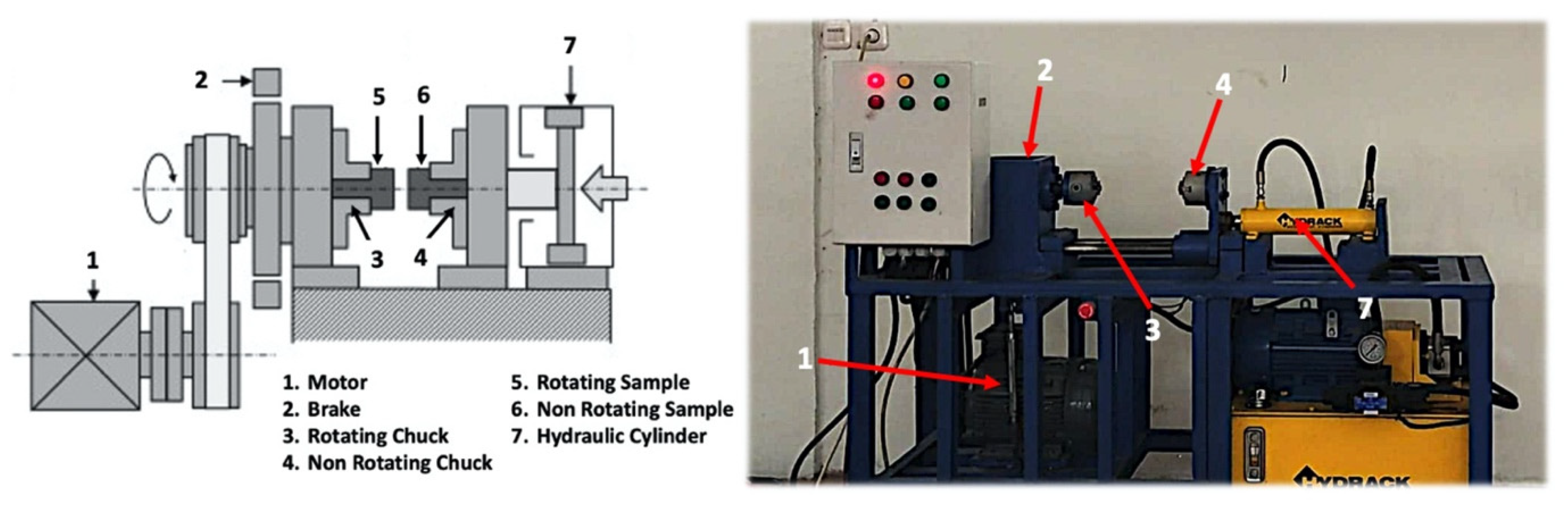
2.1. Materials and Friction Welding Method

In the present experiment, 60 mm in length and 10 mm in cross-sectional diameter SS 316 and zinc rods were utilized. Table 1 contains the chemical constituents of SS 316. All bar surfaces were polished with abrasive paper of #1000-grit and cleaned with ethanol prior to welding. For friction welding of various materials, continuous drive friction welding with capacity of 25 MPa and spindle speed of 1450 rpm were utilized (Figure 1). Stainless steel 316 was held in a revolving chuck by zinc that was held stationary. At the start of the friction welding, the revolving spindle immediately reached a certain speed (spindle speed). The specimen was then forced in the direction of rotation under high pressure (friction pressure). Under pressure, the interface between two specimens generated heat due to their relative motion. The parameters for friction welding included rotation speed, friction time, friction pressure, and forging pressure. Previous studies have employed friction times ranging from 30 s to 80 s for friction welding. This study conducted further experiments by focusing on friction time and narrowing its coverage (35 s, 40 s, and 45 s). On another occasion, friction welding was also carried out with a friction time of 35 s and an SS 316 rod was preheated at temperatures of 100 °C, 150 °C, and 200 °C. Preheating was provided to reduce the time (shortened processing time) required to complete the splice. The friction welding parameter used in this study (sample rotation speed at 1450 rpm) was according to the specification of the friction welding machine used. The friction pressure (3.9 MPa) and forging pressure (6.9 MPa) used were the results of welding experiments from previous studies.

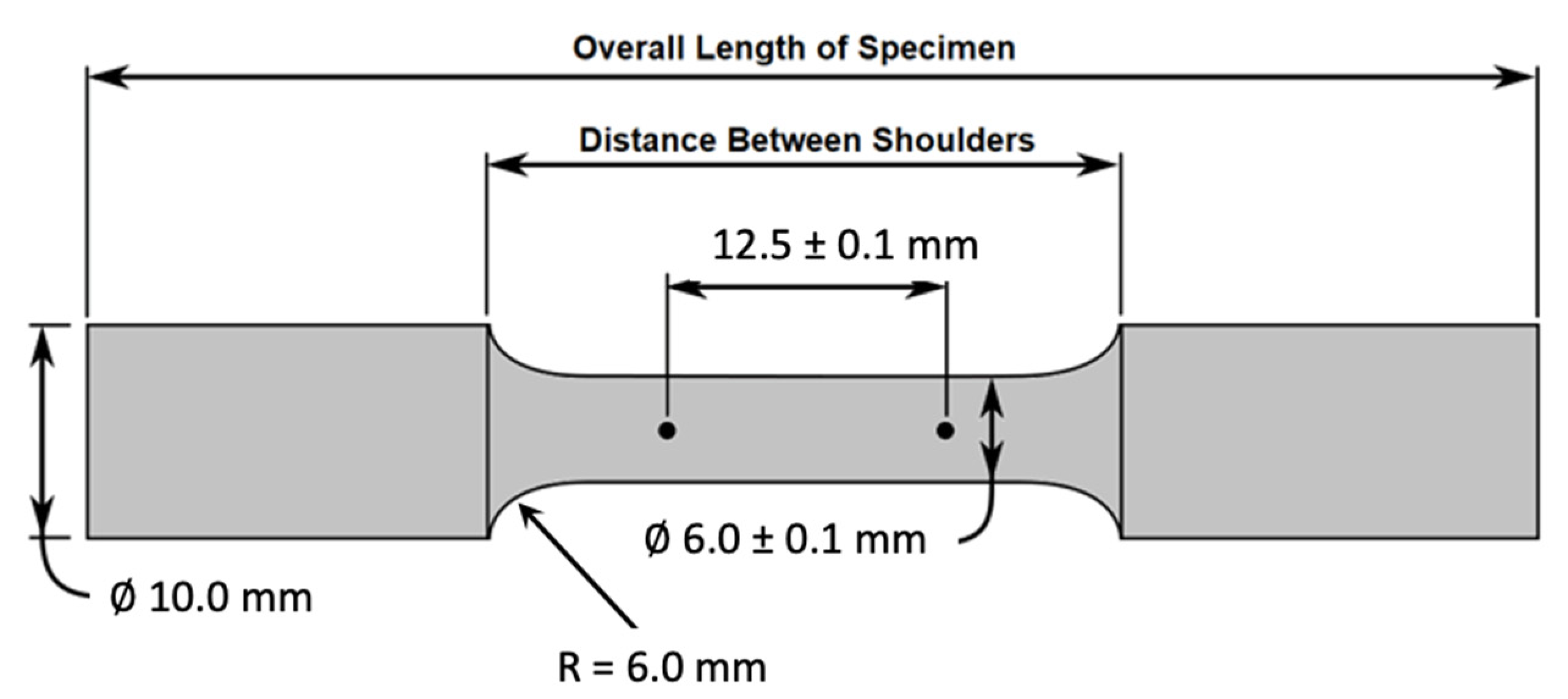
2.2. Mechanical Testing

All samples from friction welding must be cleaned using a lathe machine before the samples were made according to the standards for each test. The specimens for tensile testing were produced in accordance with the ASTM E8-2016 standard [41]. The geometry of the tensile test specimen is depicted in Figure 2. At room temperature, three sets of tensile testing were performed on a universal testing machine (TIME WDW-100E, Guiyang City, China) at a loading rate of 1.5 kN/min, and the average results were determined. A typical engineering stress-strain curve for SS 316 and a pure zinc joint is depicted in Figure 3. The readings of the three-point bending test performed on the welds adhered to the ASTM E 290-2014 standard [42]. The microhardness of welded specimens was measured in accordance with ASTM E 384-2017 [43] (West Conshohocken, PA, USA) by using a diamond pyramid indenter under 1000 gf for 10 s in a horizontal direction at 0.5 mm intervals throughout the whole weld region (Future-Tech FM-810, Kanagawa, Japan).

2.3. Characterization Analyses

The fracture specimens and fracture surface morphology were studied by using a scanning electron microscope according to the tensile testing standard (SEM-EDS, JEOL-6510 LA, Tokyo, Japan). An element mapping analysis was performed on the fracture surface of the welded joint tensile test to observe the element diffusion that happens in the welded joint as a result of each parameter. During SEM investigation, images generated on a computer screen demonstrated how the microstructure of the tensile test specimen cracks on the zinc side. The specimen microstructure and elemental percentages can be investigated by using scanning electron microscopy (SEM). The information collected from this examination permits the diffusion of elements to affect the mechanical characteristics of the specimens being welded. This section also showed data collected by scanning electron microscopy and was compared with the results of tensile testing to confirm the findings of the welded specimens’ tensile strength.

3. Results and Discussion

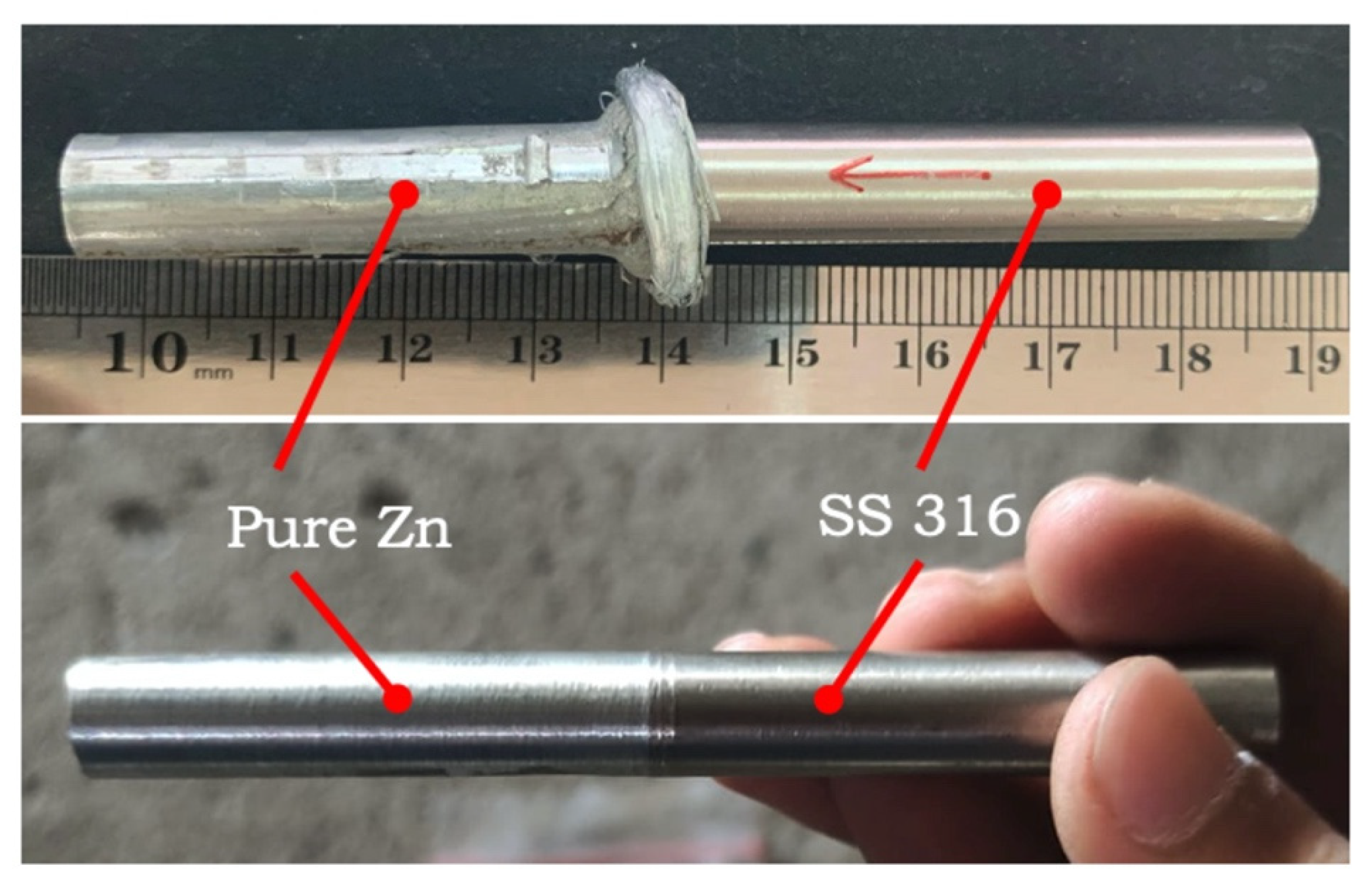
3.1. Morphology of Joint

Figure 4 depicts the typical morphology of joints between SS 316 and pure zinc. Flash was created at all joints over the full length of the weld edge direction, indicating that the forging pressure was responsible for the given deformation. The SS 316 rod ends were subjected to sufficient forging pressure so that the welding flash formed solely on the zinc side. Friction between materials with varying thermal conductivity generated non-uniform heat [29].
The flash size and form were influenced by the friction welding parameters. The size and shape of the flash were determined by the parameters of friction welding. The friction welding results: a significant deformation (large forging pressure) caused a lengthy burn-off, or a minor deformation (small forging pressure) produced a short burn-off. Next, all samples were cleaned in the flash section by using a lathe machine before proceeding to the mechanical testing stage.

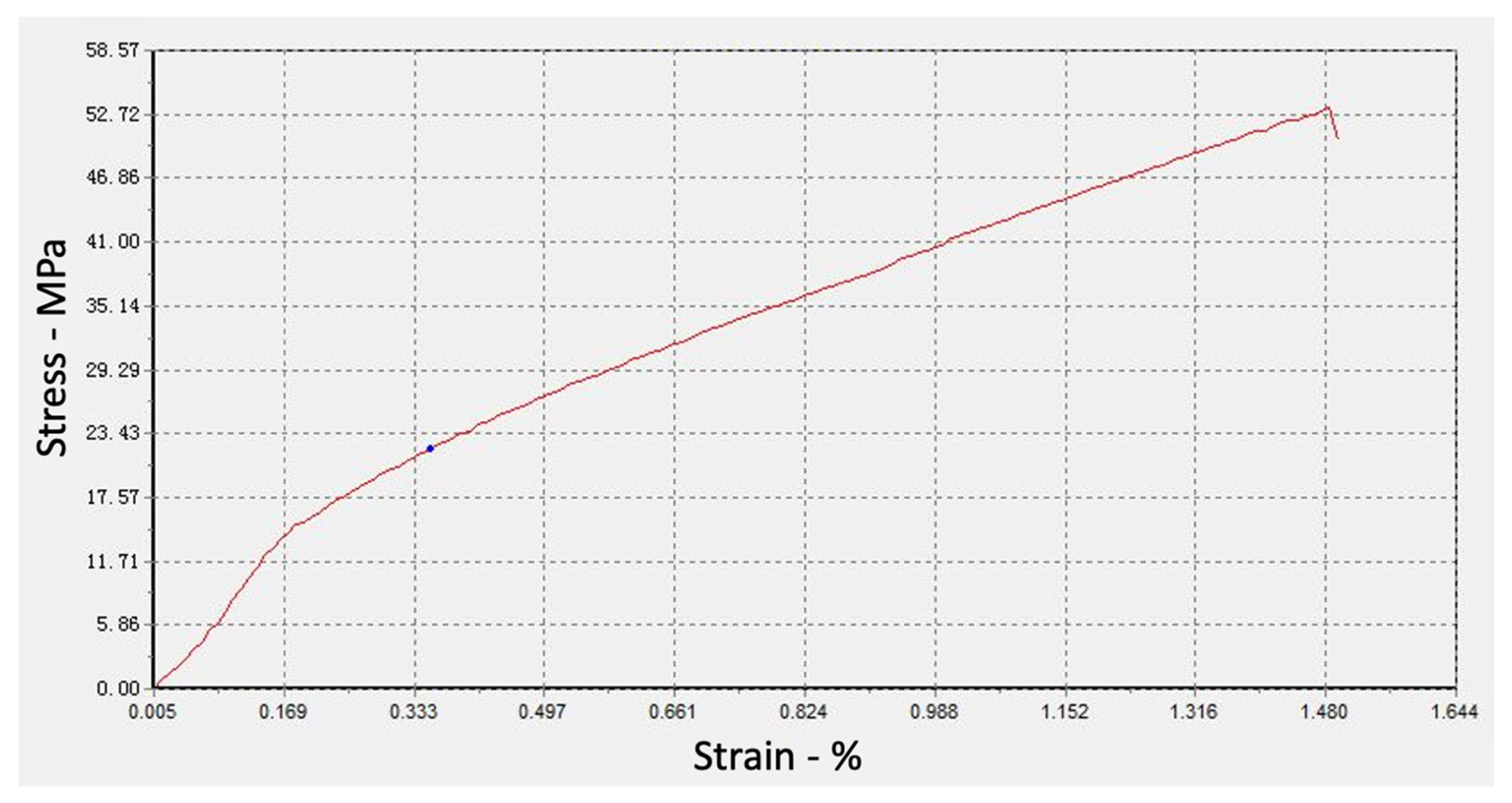
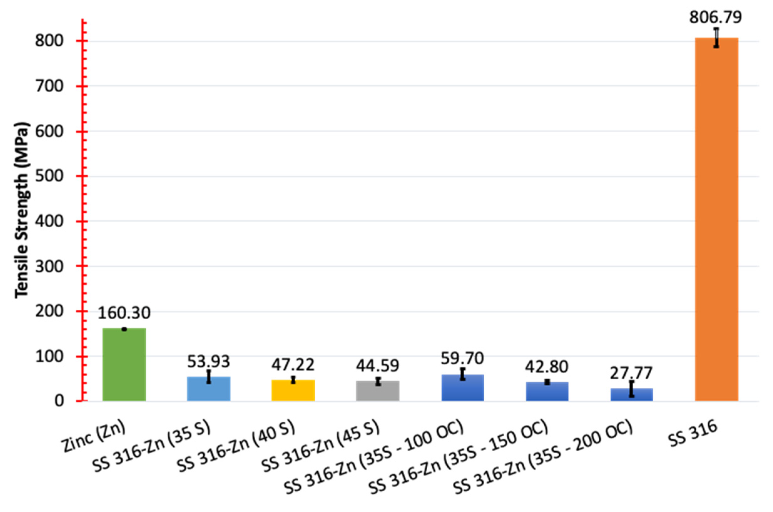
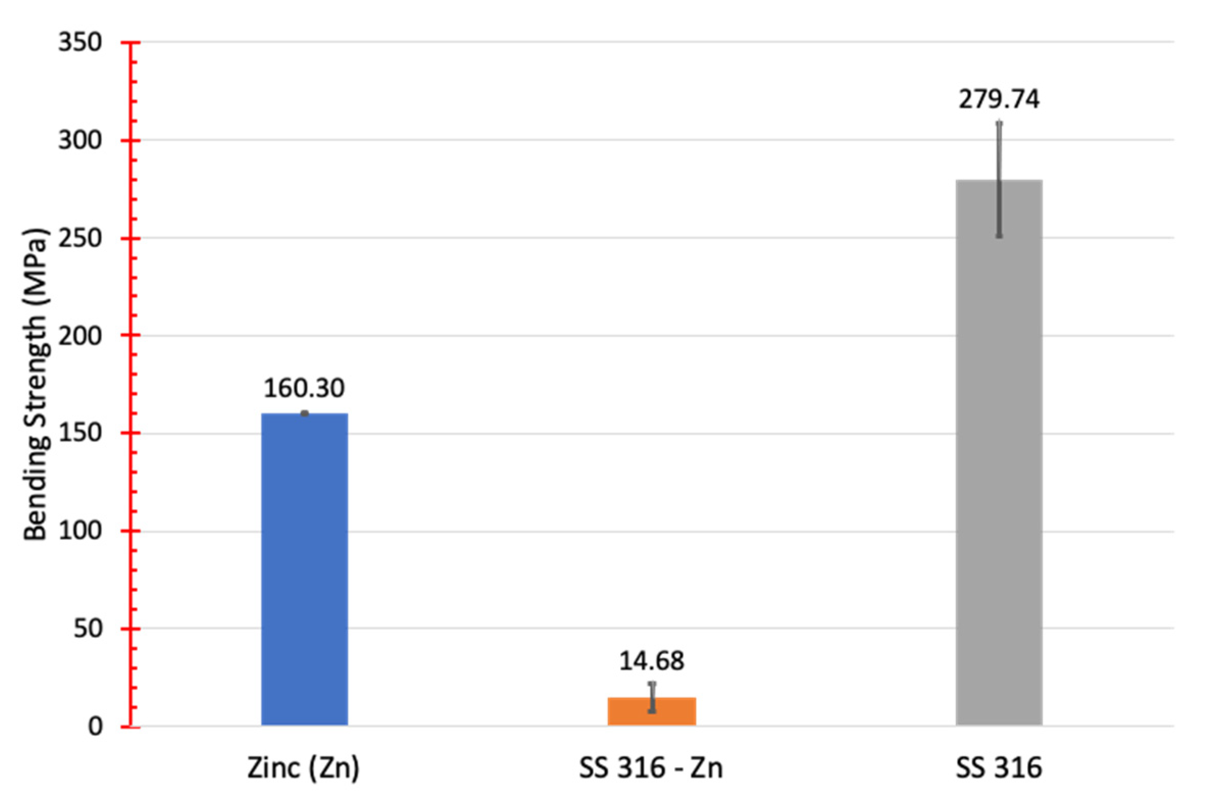
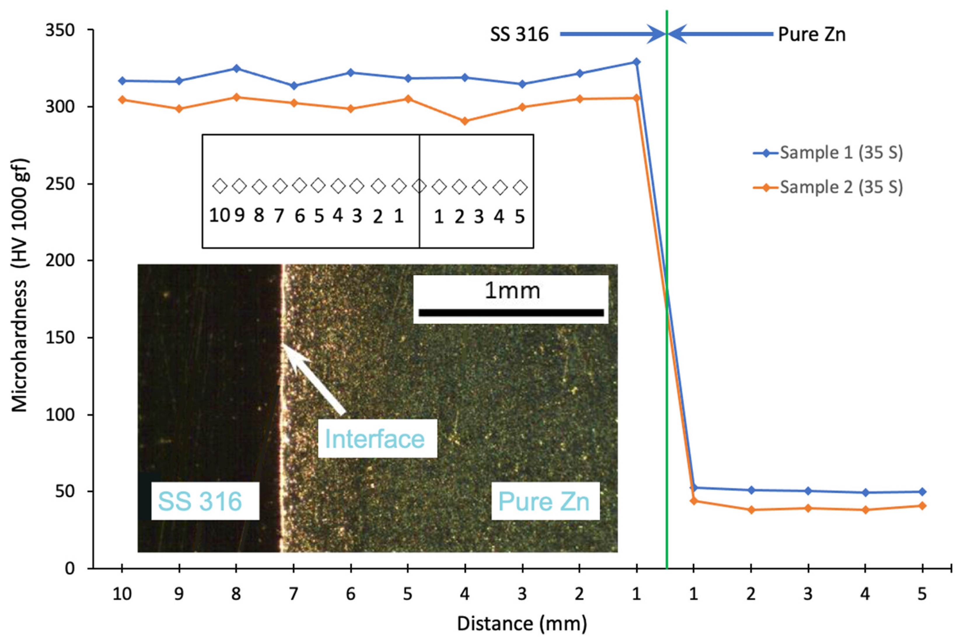
3.2. Mechanical Properties of Joint

Figure 5 compares the tensile strength of the welded joints for friction times of 35 s, 40 s, and 45 s with the base metals. Comparison of tensile strength of welded joints for friction time of 35 s with preheating of 100 °C, 150 °C, and 200 °C with base metals. Increased welding friction time diminished the joint strength. With a friction time of 35 s, a rotational speed of 1450 rpm, a friction pressure of 3.9 MPa, and a forging pressure of 6.9 MPa, the maximum tensile strength of the joint achieved was 53.93 MPa. For a friction time of 35 s with preheating of 100 °C, a rotational speed of 1450 rpm, a friction pressure of 3.9 MPa, and a forging pressure of 6.9 MPa, the maximum tensile strength of the joint achieved was 59.70 MPa.
All joints were fractured at the interface of the welds. The identical situation occurred with the AZ31-SS 316L welded junction. The fracture on the Al alloy side of the AA 6103-SS 202 joint was documented by authors in a prior work [30]. Kimura M. et al. (2016) described three types of failure for friction-welded joints, of which this is one [44].
As demonstrated in Figure 8, based on the SEM picture of the fracture surface, there is still diffusion of Fe and Cr elements on the zinc side. As friction duration increased, heat deformation occurred, resulting in the creation of a layer on the joint surface. The reason is that when friction time increases, excessive heat input occurs on the material surface, forming a coating of oxide and carbon, which reduces the joint tensile strength. The same results were achieved for a friction time of 35 s at preheating of 100 °C to increase the weld strength. In particular, higher preheating lowered the weld strength. Preheating also affected the increase of Fe, Cr, O, and C elements which caused the formation of layers at the interface. According to Senkov et al. (2016), oxide and carbide particles are defects that form a film at the interface [45].
To clarify the joint properties in detail, bending tests were used to determine the bond strength of friction-welded joints [46]. Bond strength measurements provided information on the mechanical quality and integrity of joints between base metals. The welded joints’ bending strength evaluations were conducted utilizing a three-point bending test on a Universal Testing Machine (TIME WDW-100E, China). Figure 6 shows the results of the three-point bending test for three replicates of specimens made by using friction-welded joints. The friction welded joints' maximum bending strength values were achieved with a friction time of 35 s. The friction welded joint bending strength values were insignificant with friction times of 40 s and 45 s (unreadable on the test machine) and they were not included on the graph. The obtained bending strength of 14.68 MPa was significantly lower than the base metal bending strength (Figure 6). The joints’ low bending strength may be attributed to the poor bond quality and non-diffusion bonding between base metals. The research found that friction time was an essential criterion for determining the quality of welded joints and their strength. According to Ahmad Fauzi et al. (2010), the increase in bending strength is related to heat input and high plastic deformation that occurred at the components’ interface as a result of the increased rotational speed and axial pressure [46]. Increasing the temperature of the base metal by providing preheating is expected in the sense that it can accelerate the heating of SS 316 material. Preheating can also be intended to ensure an adequate supply of additional heat energy to complete the connection. This effort was made to improve the quality of welded joint between SS 316 and pure zinc.
Figure 7 depicts the hardness values dispersion of dissimilar metal welded connections between SS 316 and pure zinc. Using the Vickers method with 1000 gf load, the hardness was determined of a number of samples. This result described a restricted interface region. The weld zones of friction-welded joints were typically split into five zones for dissimilar metals based on earlier research [4]. Originally known as the undeformed zone (UZ), this zone was unaffected by heat (base metal). The second zone was known as a partially deformed zone (PDZ) or a heat affected zone (HAZ) (HAZ). This zone was the second diffusion region of the material [4,30,47]. The third zone was called a plasticized zone (PZ).
The study results produced a narrow interface area so that only three weld zones were produced. This weld zone consists of undeformed zone (UZ) for each base metal and plasticizing zone (PZ). The plasticizing zone (PZ) was also called an intermetallic zone (IMZ). However, in this study the intermetallic zone (IMZ) was not formed, and the narrow interface area can be seen in Figure 7 (microstructure of welded joints). Previous work [30] has shown that there are three main regions visible in the interface zone of all friction-welded joints for AZ31—SS 316L.
Specifically for the plastic zone (PZ), which represents the second diffusion activity of the linked materials. If this zone is narrow, it can be claimed that the diffusion that occurs is extremely limited; conversely, if the diffusion that occurs is very vast, this zone can become wide. According to Elikyürek et al. (2011), each of these zones’ widths are dependent on the welding parameter [48]. Each of these zones’ breadths depend on the thermal conductivity of the material being welded [49], according to Kurt A. et al. (2011). This (narrow zone) was also discovered by Nasution et al. (2019) while welding AZ31 to SS 316L [30].

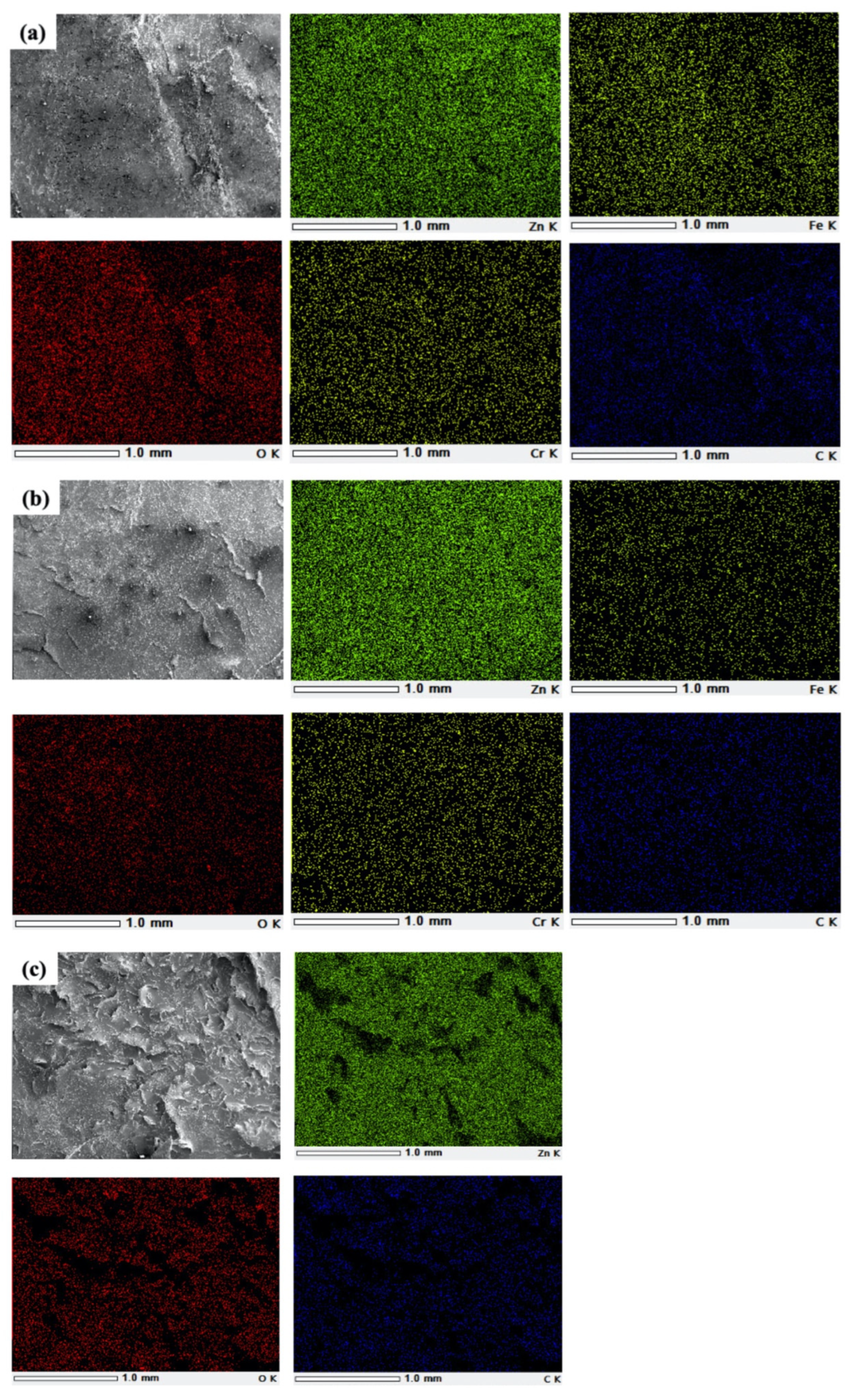
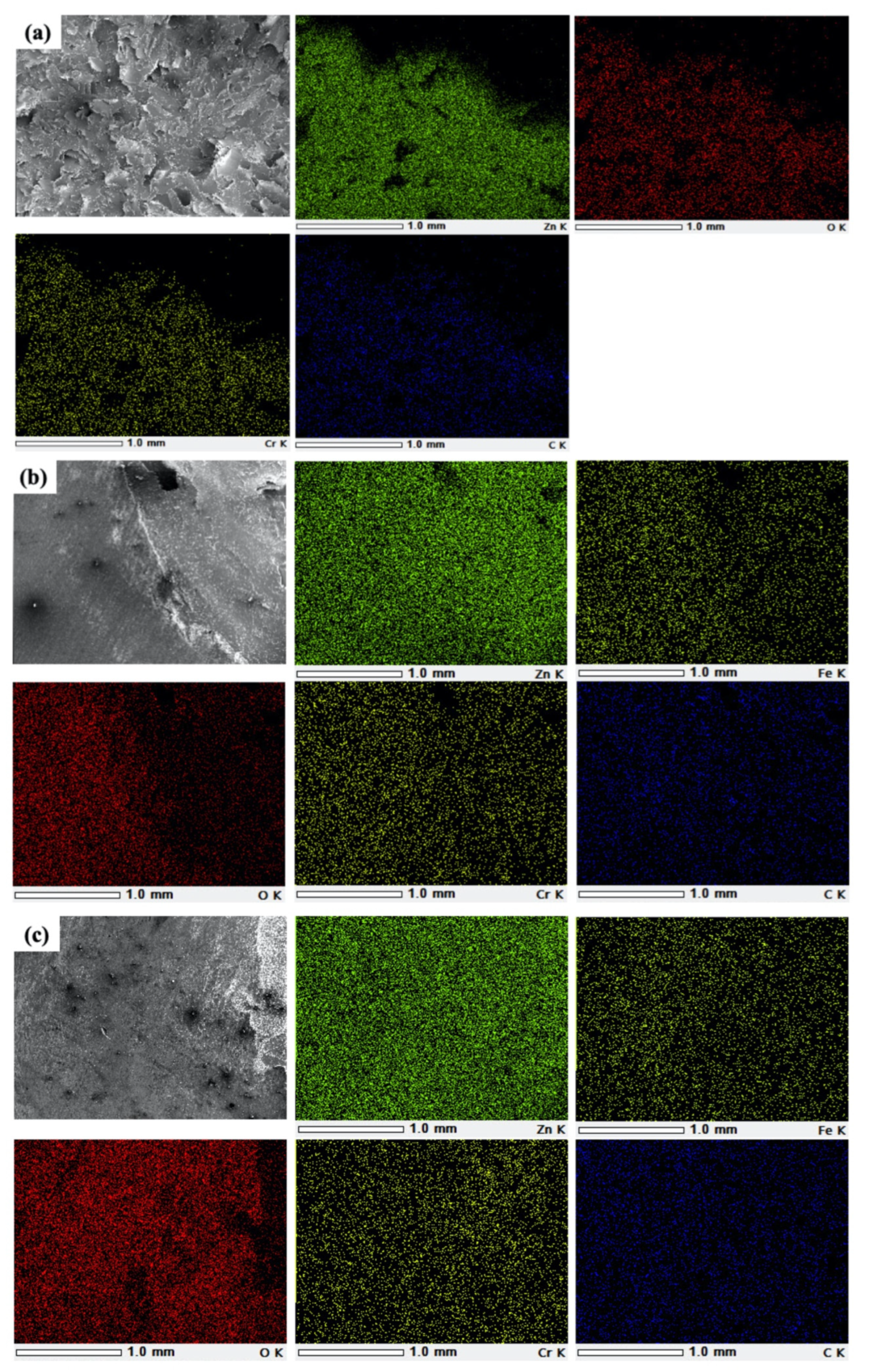
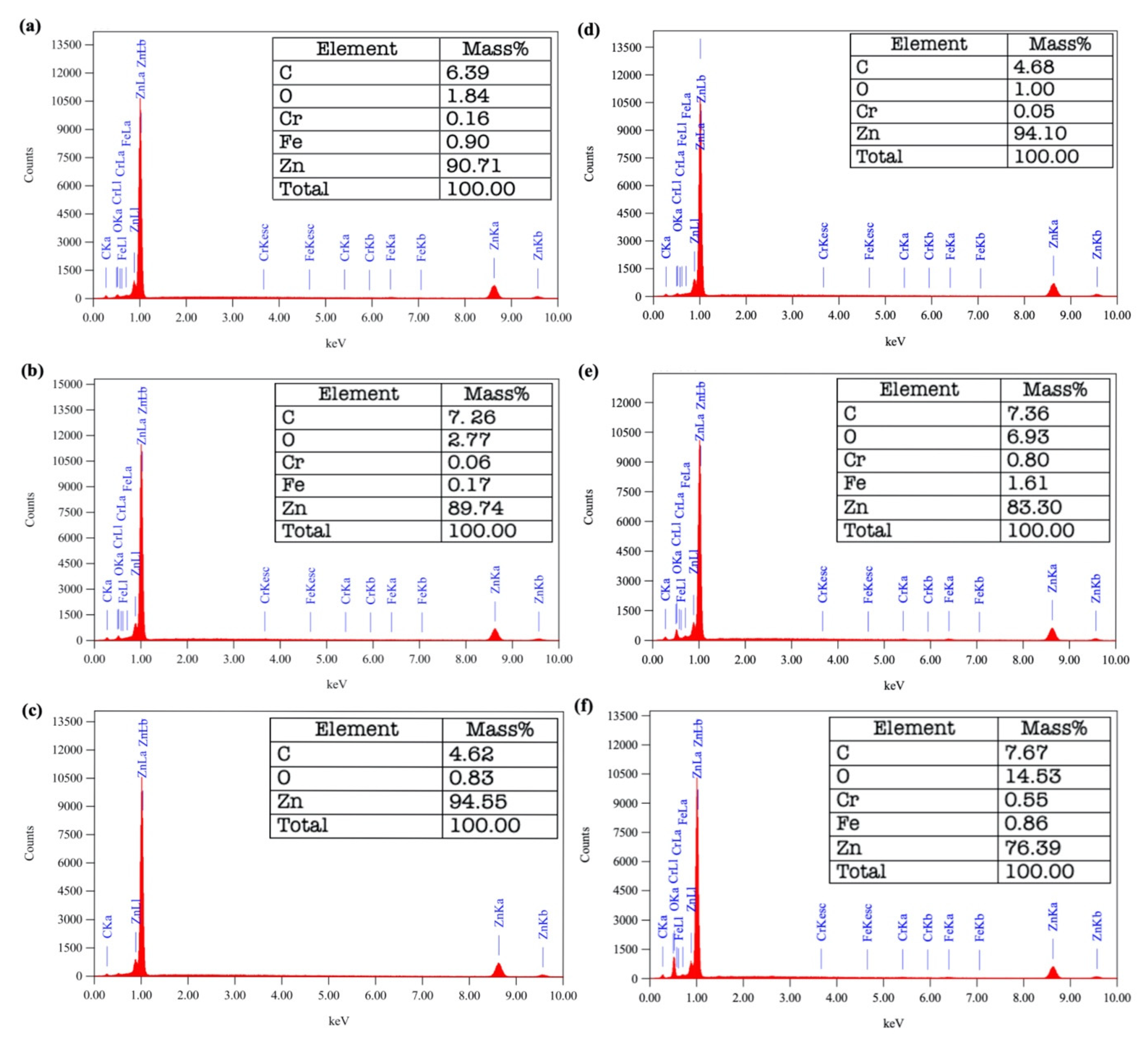
3.3. Microstructure of Joint

The formation of a PZ zone at the weld interface has occurred. It cannot be validated using an optical microscope due to its thinness (Figure 7). As demonstrated in Figure 8 and Figure 9, based on the SEM picture of the fracture surface, there was still residual of SS 316 on the zinc-only side. To ensure that the interface between SS 316 and pure zinc is formed in the PZ zone as a result of the solid-state reaction between SS 316 and pure zinc during welding. Figure 8 and Figure 9 illustrate the mapping of pure zinc SS 316 connector elements. At the weld interface, elements Fe and Cr diffused to form the PZ zone; whereas, O and C were measured through oxidation caused by the contact between two metals. To ensure that the interface between SS 316 and pure zinc formed in PZ zone as a result of the solid-state reaction between SS 316 and pure zinc during welding. Figure 8 and Figure 9 depict the mapping of pure zinc SS 316 connector elements. At the weld interface, elements Fe and Cr diffused to form the PZ zone. O and C were measured through oxidation caused by the contact between the two metals. According to Senkov et al. [45], the induction of friction between the two base metals resulted in larger carbide and oxide particles. At the interface of the pure zinc fracture side for the 35 s sample (Figure 8a) and 40 s sample (Figure 8b), the dark yellow, red, light yellow, and blue curves were scattered, respectively. The 45 s sample (Figure 8c) contained only the red and blue curves. For the fracture side interface of pure zinc in the preheat-treated sample at 35 s—100 °C (Figure 9a), red, light yellow, and blue curves can be observed. The 35 s—150 °C sample (Figure 9b) and the 35 s—200 °C sample (Figure 9c) showed scattered dark yellow, red, light yellow, and blue curves. Figure 10 is a point analysis (EDS) of the fracture surface resulting from the tensile test.
For the 35 s and 40 s samples, EDS analysis (Table 2) showed the presence of approximately Zn, Fe, O, Cr, and C. On the other hand, EDS analysis for the 45 s sample only detected Zn, O, and C. This meant that with an increase in friction time, more oxide formed on the surface of the metal and prevented the diffusion process. As for the preheated samples, which showed 35 s—100 °C samples, EDS analysis showed the presence of Zn, O, Cr, and C. Meanwhile, for the 35 s—150 °C sample and 35 s—200 °C sample, EDS analysis detected all (Fe, Cr, O, and C). Table 2 also shows that by increasing the preheating temperature, there was a significant increase in O and C elements. The preheating process increased the interfacial bond strength by promoting film growth. Fuji A. et al. (1997) stated that the formation of an intermetallic phase at the weld interface is a necessary condition for achieving an adequate bond formation during friction welding of dissimilar materials [50]. This intermetallic phase is produced by the diffusion of the elements present in the welded metal. However, many of the weld strength qualities that resulted from the combination of alloy components are unacceptable. This occurs during friction welding of metals with a low affinity for oxygen. Meanwhile, metals with a strong affinity for oxygen will develop an oxide layer to prevent diffusion. The strength of the welded joint, according to Liu Y. et al. (2020) is greatly influenced by the formation of a hard and brittle intermetallic phase at the interface [51]. Recent research from Liu, F.C. et al. (2020) on forming nanoscale amorphous alloys at the Al-Fe interface is one of the offers for development in the design of amorphous new alloys and dissimilar metal joining techniques [52]. Good joints are also found in AA 6103–SS 202 with an average intermetallic zone width of 0.4 mm [30].

4. Conclusions

The experimental examination of friction-welded SS 316-pure zinc joints demonstrated that the welding parameters have a significant impact on the friction welding process. The findings of experiments involving the short friction time during the friction welding process led to an increase in tensile strength. Preheat treatment at 100 °C can encourage film growth which increases the interfacial bond strength. The fracture surface of SS 316-pure zinc tensile test results indicated that an oxide layer will form on the metal surface with increasing of friction time. Increasing the preheating temperature can also increase the amount of O and C elements significantly so it inhibits the diffusion process. In addition, the diffusion process is very important because it allows the production of an intermetallic phase for joint strength. This investigation could also lead to additional research into the multilayer friction welding techniques or could design new alloy amorphization and joining techniques for dissimilar metals.

Author Contributions

M.R., H.D. and A.K.N. conceived and designed the experiments; S.A.Z. carried out the experiments; M.R., H.D. and A.K.N. analyzed the experimental data and wrote the manuscript. All authors have read and agreed to the published version of the manuscript.

Funding

The authors would like to thank the financial support from The Ministry of Education, Culture, Research, and Technology of The Republic of Indonesia through contract number: 086/E5/PG.02.00.PT/2022.

Conflicts of Interest

The authors declare that there are no conflict of interest.

References

  1. Kumar Rajak, D.; Pagar, D.D.; Menezes, P.L.; Eyvazian, A. Friction-based welding processes: Friction welding and friction stir welding. J. Adhes. Sci. Technol. 2020, 34, 2613–2637. [Google Scholar] [CrossRef]
  2. Ananda Rao, G.; Ramanaiah, N. Dissimilar metals AISI 304 steel and AA 2219 aluminium alloy joining by friction welding method. Mater. Today Proc. 2019, 19, 902–907. [Google Scholar] [CrossRef]
  3. Rafi, H.K.; Ram, G.D.J.; Phanikumar, G.; Rao, K.P. Microstructure and tensile properties of friction welded aluminum alloy AA7075-T6. Mater. Des. (1980–2015) 2010, 31, 2375–2380. [Google Scholar] [CrossRef]
  4. Nasution, A.K.; Murni, N.S.; Sing, N.B.; Idris, M.H.; Hermawan, H. Partially degradable friction-welded pure iron–stainless steel 316L bone pin. J. Biomed. Mater. Res. Part B Appl. Biomater. 2015, 103, 31–38. [Google Scholar] [CrossRef] [PubMed]
  5. Sathishkumar, G.B.; Sethuraman, P.; Chanakyan, C.; Sundaraselvan, S.; Joseph Arockiam, A.; Alagarsamy, S.V.; Elmariung, A.; Meignanamoorthy, M.; Ravichandran, M.; Jayasathyakawin, S. Friction welding of similar and dissimilar materials: A review. Mater. Today Proc. 2021. [Google Scholar] [CrossRef]
  6. Basmaci, A.N.; Filiz, S.; Şahin, M. Experimental Analysis of Welded Rods with a Functionally Graded Material Approach. Appl. Sci. 2020, 10, 3908. [Google Scholar] [CrossRef]
  7. Pratyusha, M.; Ramana, P.V.; Prasanthi, G. Evaluation of tensile strength of dissimilar metal pure aluminium and pure copper friction welds. Mater. Today Proc. 2021, 38, 2271–2274. [Google Scholar] [CrossRef]
  8. Nasution, A.K.; Gustami, H.; Suprastio, S.; Fadillah, M.A.; Octavia, J.; Saidin, S. Potential use of Friction Welding for Fabricating Semi-Biodegradable Bone Screws. Int. J. Automot. Mech. Eng. 2022, 19, 9660–9667. [Google Scholar] [CrossRef]
  9. Ramesh Kumar, R.; Babu, J.M.; Saleh, B.; Fayaz, H.; Chandrashekar, A.; Gera, T.; Nisar, K.S.; Saleel, C.A. Experimental and analytical investigation on friction welding dissimilar joints for aerospace applications. Ain Shams Eng. J. 2023, 14, 101853. [Google Scholar] [CrossRef]
  10. Li, W.; Vairis, A.; Preuss, M.; Ma, T. Linear and rotary friction welding review. Int. Mater. Rev. 2016, 61, 71–100. [Google Scholar] [CrossRef]
  11. Ahmad Mir, F.; Zaman Khan, N.; Noor Siddiquee, A.; Parvez, S. Friction based solid state welding—A review. Mater. Today Proc. 2022, 62, 55–62. [Google Scholar] [CrossRef]
  12. Tiley, J.S.; Mahaffey, D.W.; Alam, T.; Rojhirunsakool, T.; Senkov, O.; Parthasarthy, T.; Banerjee, R. Strengthening mechanisms in an inertia friction welded nickel-base superalloy. Mater. Sci. Eng. A 2016, 662, 26–35. [Google Scholar] [CrossRef]
  13. Guo, W.; You, G.; Yuan, G.; Zhang, X. Microstructure and mechanical properties of dissimilar inertia friction welding of 7A04 aluminum alloy to AZ31 magnesium alloy. J. Alloys Compd. 2017, 695, 3267–3277. [Google Scholar] [CrossRef]
  14. Mogami, H.; Matsuda, T.; Sano, T.; Yoshida, R.; Hori, H.; Hirose, A. High-frequency linear friction welding of aluminum alloys. Mater. Des. 2018, 139, 457–466. [Google Scholar] [CrossRef]
  15. Matsuda, T.; Adachi, H.; Sano, T.; Yoshida, R.; Hori, H.; Ono, S.; Hirose, A. High-frequency linear friction welding of aluminum alloys to stainless steel. J. Mater. Process. Technol. 2019, 269, 45–51. [Google Scholar] [CrossRef]
  16. Craine, R.E.; Francis, A. Frictional heat generated in the early stages of an orbital friction welding process. Wear 1987, 114, 355–365. [Google Scholar] [CrossRef]
  17. Raab, U.; Levin, S.; Wagner, L.; Heinze, C. Orbital friction welding as an alternative process for blisk manufacturing. J. Mater. Process. Technol. 2015, 215, 189–192. [Google Scholar] [CrossRef]
  18. Shanjeevi, C.; Arputhabalan, J.; Pavithran, E.; Raju, B. Prediction of Optimized Friction Welding Parameter for Joining of Dissimilar Material using Friction Welding. Mater. Today Proc. 2019, 16, 838–842. [Google Scholar] [CrossRef]
  19. Paventhan, R.; Lakshminarayanan, P.R.; Balasubramanian, V. Optimization of Friction Welding Process Parameters for Joining Carbon Steel and Stainless Steel. J. Iron Steel Res. Int. 2012, 19, 66–71. [Google Scholar] [CrossRef]
  20. Hiroshi, K. Application of Linear Friction Welding Technique to Aircraft Engine Parts. IHI Eng. Rev. 2014, 47, 40–43. [Google Scholar]
  21. Banerjee, A.; Ntovas, M.; Da Silva, L.; Rahimi, S. Microstructure and mechanical properties of dissimilar inertia friction welded 316L stainless steel to A516 ferritic steel for potential applications in nuclear reactors. Manuf. Lett. 2022, 33, 33–37. [Google Scholar] [CrossRef]
  22. Anant Sagar, D.B.; Pardhu, Y.; Rao, M.S.K.; Narasaiah, N. Strain hardening behavior of friction welded beta titanium alloy Titan 1023 used for aeronautical applications. Mater. Today Proc. 2022, 57, 687–692. [Google Scholar] [CrossRef]
  23. Rehman, A.U.; Kishore Babu, N.; Talari, M.K.; Anwar, S.; Usmani, Y.; Al-Samhan, A.M. Dissimilar Rotary Friction Welding of Inconel 718 to F22 Using Inconel 625 Interlayer. Appl. Sci. 2021, 11, 10684. [Google Scholar] [CrossRef]
  24. Verma, G.; Kumar, S.; Bundel, B.R. A Research paper on the Comparison of Weld Strength of Friction Welding of Different Materials at two Different RPM. Int. J. Mech. Eng. Technol. 2016, 7, 123–127. [Google Scholar]
  25. Handa, A.; Chawla, V. Experimental study of mechanical properties of friction welded AISI 1021 steels. Sadhana 2013, 38, 1407–1419. [Google Scholar] [CrossRef] [Green Version]
  26. Zulu, M.C.; Mashinini, P.M. Process optimization of rotary friction welding of Ti-6Al-4V alloy rods. IOP Conf. Ser. Mater. Sci. Eng. 2018, 430, 012012. [Google Scholar] [CrossRef]
  27. Ramesh, A.P.; Subramaniyan, M.; Eswaran, P. Review on Friction Welding of Similar/Dissimilar Metals. J. Phys. Conf. Ser. 2019, 1362, 012032. [Google Scholar] [CrossRef]
  28. Skowrońska, B.; Bober, M.; Kołodziejczak, P.; Baranowski, M.; Kozłowski, M.; Chmielewski, T. Solid-State Rotary Friction-Welded Tungsten and Mild Steel Joints. Appl. Sci. 2022, 12, 9034. [Google Scholar] [CrossRef]
  29. Winiczenko, R.; Goroch, O.; Krzyńska, A.; Kaczorowski, M. Friction welding of tungsten heavy alloy with aluminium alloy. J. Mater. Process. Technol. 2017, 246, 42–55. [Google Scholar] [CrossRef]
  30. Nasution, A.K.; Nawangsari, P.; Junaidi, A.; Hermawan, H. Friction welding of AZ31-SS316L for partially-degradable orthopaedic pins. IOP Conf. Ser. Mater. Sci. Eng. 2019, 532, 012014. [Google Scholar] [CrossRef]
  31. Mir, F.A.; Khan, N.Z.; Parvez, S. Recent advances and development in joining ceramics to metals. Mater. Today Proc. 2021, 46, 6570–6575. [Google Scholar] [CrossRef]
  32. Uday, M.B.; Ahmad-Fauzi, M.N.; Noor, A.M.; Rajoo, S. An insight into microstructural evolution during plastic deformation in AA6061 alloy after friction welding with alumina-YSZ composite. Mech. Mater. 2015, 91, 50–63. [Google Scholar] [CrossRef]
  33. Rombaut, P.; De Waele, W.; Faes, K. Friction welding of steel to ceramic. In Sustainable Construction and Design 2011 (SCAD); Ghent University, Laboratory Soete: Ghent, Belgium, 2011; Volume 2011. [Google Scholar]
  34. Li, P.; Li, J.; Dong, H.; Ji, C. Metallurgical and mechanical properties of continuous drive friction welded copper/alumina dissimilar joints. Mater. Des. 2017, 127, 311–319. [Google Scholar] [CrossRef]
  35. Goodwin, F.E. Zinc and Zinc Alloys. In Springer Handbook of Materials Data; Warlimont, H., Martienssen, W., Eds.; Springer International Publishing: Cham, Switzerland, 2018; pp. 431–442. [Google Scholar] [CrossRef]
  36. Liu, H.; Zuo, Y.; Ji, S.; Dong, J.; Zhao, H. Friction stir solid–liquid spot welding of Cu to Al assisted by Zn interlayer. J. Mater. Res. Technol. 2022, 18, 85–95. [Google Scholar] [CrossRef]
  37. Khajeh, R.; Jafarian, H.R.; Jabraeili, R.; Eivani, A.R.; Seyedein, S.H.; Park, N.; Heidarzadeh, A. Strength-ductility synergic enhancement in friction stir welded AA2024 alloy and copper joints: Unravelling the role of Zn interlayer's thickness. J. Mater. Res. Technol. 2022, 16, 251–262. [Google Scholar] [CrossRef]
  38. Delgado-Pamanes, M.; Alvarez-Montufar, J.; Reyes-Osorio, L.; Garza, C.; Suárez-Rosales, M.; Chávez-Alcalá, J. Evaluation of optimal processing parameters for a Zn-based eutectoid alloy processed by friction-stir welding. J. Mater. Res. Technol. 2022, 18, 3256–3265. [Google Scholar] [CrossRef]
  39. Zheng, Q.; Feng, X.; Shen, Y.; Huang, G.; Zhao, P. Dissimilar friction stir welding of 6061 Al to 316 stainless steel using Zn as a filler metal. J. Alloys Compd. 2016, 686, 693–701. [Google Scholar] [CrossRef]
  40. Triouleyre, J. Friction welding of zinc. Mater. Des. 1984, 5, 107–111. [Google Scholar] [CrossRef]
  41. ASTM E8; Standard Test Methods for Tension Testing of Metallic Materials. ASTM International: West Conshohocken, PA, USA, 2016.
  42. ASTM E290-14; Standard Test Methods for Bend Testing of Material for Ductility. ASTM International: West Conshohocken, PA, USA, 2014.
  43. ASTM E384; Standard Test Method for Microindentation Hardness of Materials. ASTM International: West Conshohocken, PA, USA, 2017.
  44. Kimura, M.; Kusaka, M.; Kaizu, K.; Nakata, K.; Nagatsuka, K. Friction welding technique and joint properties of thin-walled pipe friction-welded joint between type 6063 aluminum alloy and AISI 304 austenitic stainless steel. Int. J. Adv. Manuf. Technol. 2016, 82, 489–499. [Google Scholar] [CrossRef]
  45. Senkov, O.N.; Mahaffey, D.W.; Semiatin, S.L. Effect of Preheating on the Inertia Friction Welding of the Dissimilar Superalloys Mar-M247 and LSHR. Metall. Mater. Trans. A 2016, 47, 6121–6137. [Google Scholar] [CrossRef]
  46. Ahmad Fauzi, M.N.; Uday, M.B.; Zuhailawati, H.; Ismail, A.B. Microstructure and mechanical properties of alumina-6061 aluminum alloy joined by friction welding. Mater. Des. 2010, 31, 670–676. [Google Scholar] [CrossRef]
  47. Sathiya, P.; Aravindan, S.; Noorul Haq, A. Effect of friction welding parameters on mechanical and metallurgical properties of ferritic stainless steel. Int. J. Adv. Manuf. Technol. 2007, 31, 1076–1082. [Google Scholar] [CrossRef]
  48. Çelikyürek, İ.; Torun, O.; Baksan, B. Microstructure and strength of friction-welded Fe–28Al and 316 L stainless steel. Mater. Sci. Eng. A 2011, 528, 8530–8536. [Google Scholar] [CrossRef]
  49. Kurt, A.; Uygur, I.; Paylasan, U. Effect of Friction Welding Parameters on Mechanical and Microstructural Properties of Dissimilar AISI 1010-ASTM B22 Joints. Weld. J. 2011, 90, 102–106. [Google Scholar]
  50. Fuji, A.; Kimura, M.; North, T.H.; Ameyama, K.; Aki, M. Mechanical properties of titanium-5083 aluminium alloy friction joints. Mater. Sci. Technol. 1997, 13, 673–678. [Google Scholar] [CrossRef]
  51. Liu, Y.; Zhao, H.; Peng, Y. Metallurgical reaction and joining phenomena in friction welded Al/Fe joints. Int. J. Adv. Manuf. Technol. 2020, 107, 1713–1723. [Google Scholar] [CrossRef]
  52. Liu, F.C.; Dong, P.; Zhang, J.; Lu, W.; Taub, A.; Sun, K. Alloy amorphization through nanoscale shear localization at Al-Fe interface. Mater. Today Phys. 2020, 15, 100252. [Google Scholar] [CrossRef]
Figure 1. The image of experimental equipment and rotary friction welded SS 316-pure Zn.
Applsci 13 00988 g001
Figure 2. The schematic diagram of tensile specimen.
Applsci 13 00988 g002
Figure 3. Typical engineering stress-strain curve of SS 316-pure Zn joint (friction time at 35 s, rotation speed at 1450 rpm, friction pressure at 3.9 MPa, and forging pressure at 6.9 MPa).
Applsci 13 00988 g003
Figure 4. The morphology of the welded joint and removal of flash on sample after friction welding process.
Applsci 13 00988 g004
Figure 5. Tensile strength of SS 316-pure Zn joints rotary friction-welding (friction time of 35 s, 40 s, 45 s, 35 s—100 °C, 35 s—150 °C, and 35 s—200 °C, rotation speed at 1450 rpm, friction pressure at 3.9 MPa, and forging pressure at 6.9 MPa) with base metals.
Applsci 13 00988 g005
Figure 6. Bending strength of SS 316-pure Zn joints (friction time of 35 s) with base metals.
Applsci 13 00988 g006
Figure 7. Hardness distribution across the weld of SS 316-pure Zn from two samples with friction time of 35 s.
Applsci 13 00988 g007
Figure 8. EDS map analysis: (a) 35 s sample, (b) 40 s sample, and (c) 45 s sample.
Applsci 13 00988 g008
Figure 9. EDS map analysis: (a) 35 s—100 °C sample, (b) 35 s—150 °C sample, and (c) 35 s—200 °C sample.
Applsci 13 00988 g009
Figure 10. Spot analysis (EDS) at the fracture surface of tensile test results: (a) 35 s sample, (b) 40 s sample, (c) 45 s sample, (d) 35 s—100 °C sample, (e) 35 s—150 °C sample, and (f) 35 s—200 °C sample.
Applsci 13 00988 g010
Table 1. Chemical composition of 316 stainless steel (wt.%).
C.MnPSSiCrNiNMoFe
0.0802.0000.0450.0300.75016.00–18.0010.00–14.000.1002.000–3.000Bal.
Table 2. The composition of position in Figure 8 and Figure 9 (wt.%).
SampleZnFeOCrC
35 s Sample90.710.901.840.166.39
40 s Sample89.740.172.770.067.26
45 s Sample94.55-0.83-4.62
35 s—100 °C Sample94.10-1.000.054.68
35 s—150 °C Sample83.301.616.930.807.36
35 s—200 °C Sample76.390.8614.530.557.67
Disclaimer/Publisher’s Note: The statements, opinions and data contained in all publications are solely those of the individual author(s) and contributor(s) and not of MDPI and/or the editor(s). MDPI and/or the editor(s) disclaim responsibility for any injury to people or property resulting from any ideas, methods, instructions or products referred to in the content.

