
Creep Analysis of Rotating Thick Cylinders Subjected to External and Internal Pressure: Analytical and Numerical Approach


Abstract
:1. Introduction
2. Mathematical Formulation
2.1. Analytical Analysis
- (i)
- Incompressible and isotropic cylinder material with uniform distribution of silicon carbide in aluminum matrix.
- (ii)
- Gradual increase in applied pressure but remains constant during loading history.
- (iii)
- Steady-state condition of stress at any point in the cylinder.
- (iv)
- Small elastic deformations can be neglected in comparison with creep deformations.
2.2. Von Mises Criterion
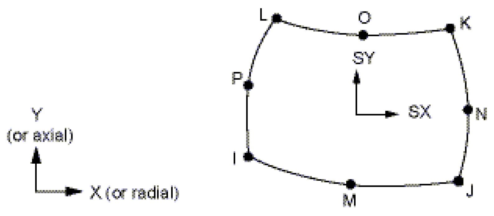
3. Numerical Analysis and FEA Model
4. Analytical and Numerical Solutions
5. Conclusions
- Analytical and numerical solutions, using FEA, of the creep problem in rotating thick cylinders made of Al-SiCp composite and subjected to internal and external pressures were successfully achieved.
- All results of the stresses, strains, and strain rates distributions obtained are found to be in full agreement with the published data.
- All plotted results of the stresses, strains, and strain rate distributions obtained through the analytical approach were found to be in excellent compliance with those solutions obtained using finite element analysis (FEA).
- FEA Model was verified through a calculated model from exact analytical analysis.
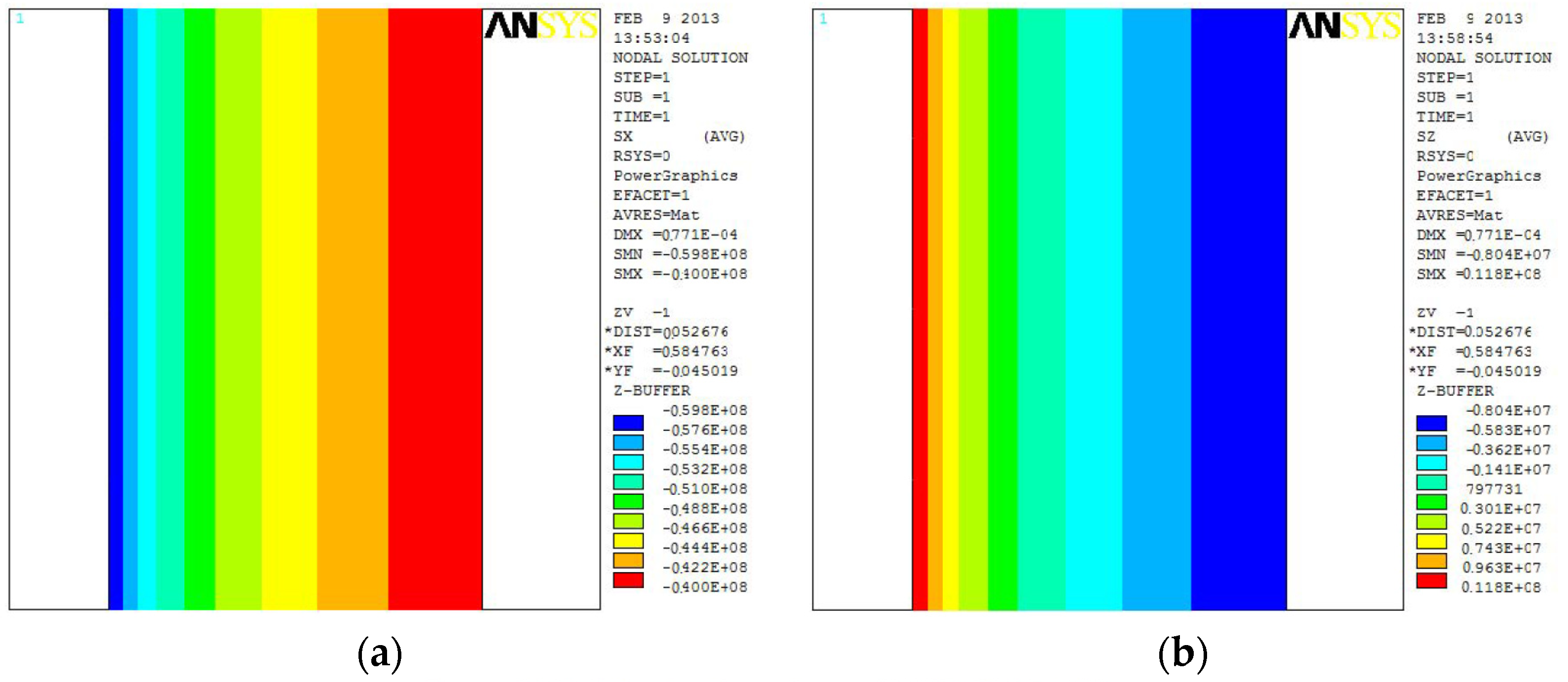
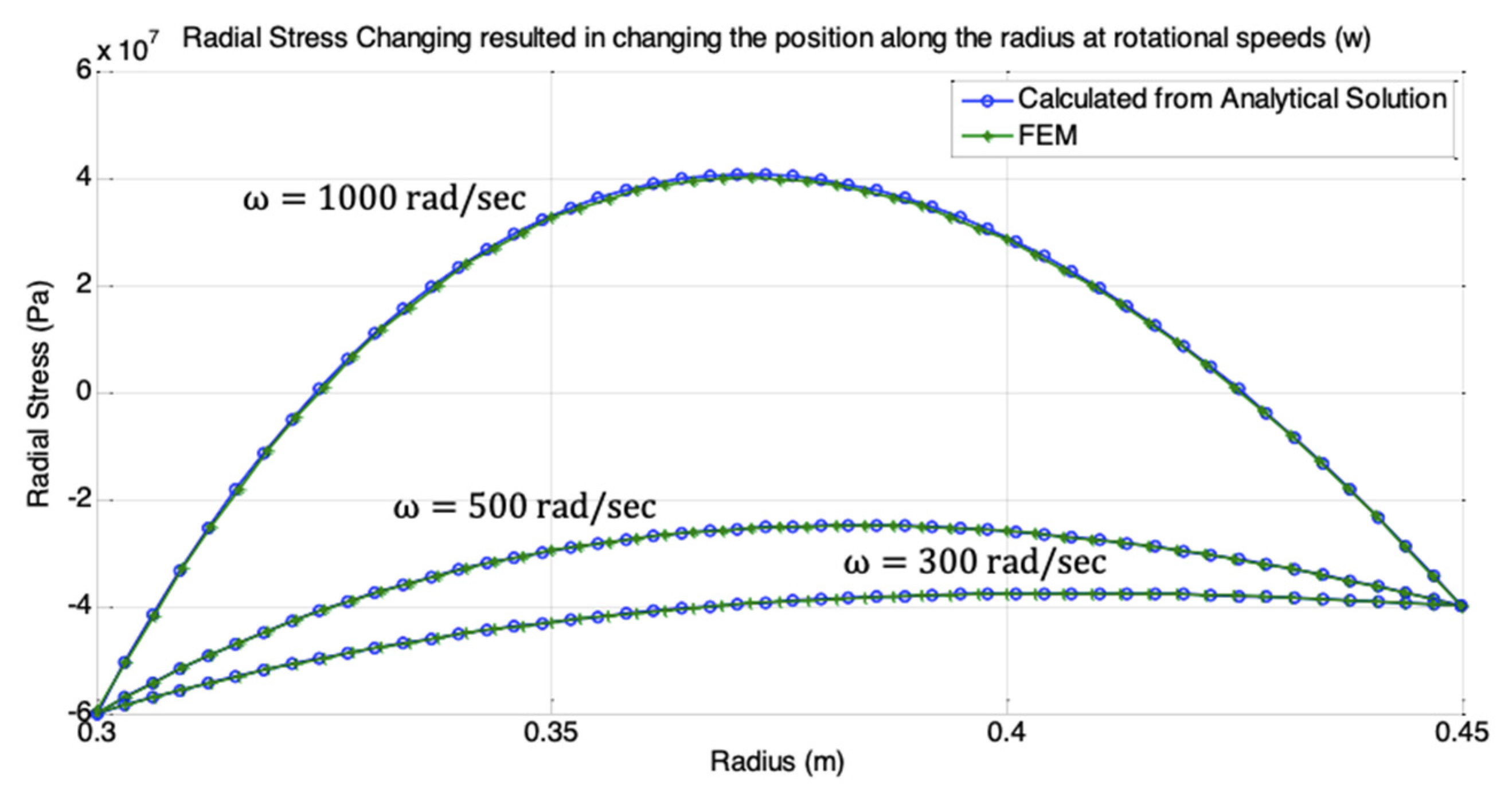
- The radial stresses obtained from analytical and numerical solutions are constant at the inner and outer surfaces, but they are higher at radius for .
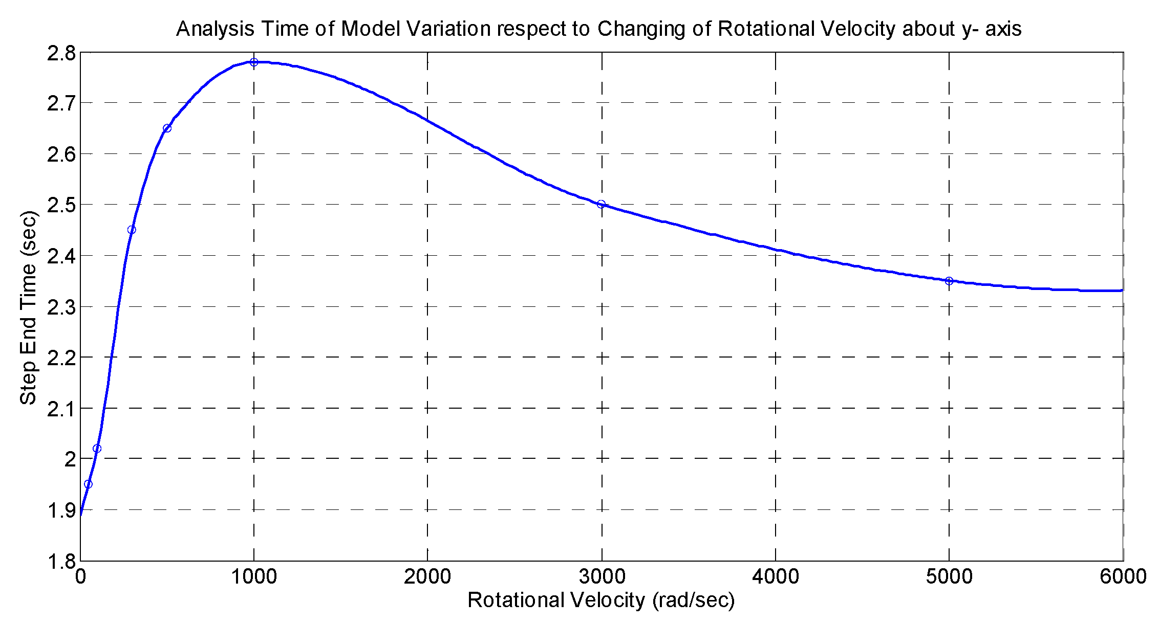
- The radial stresses obtained from analytical and numerical solutions, increase gradually with an increase in the rotational velocity .
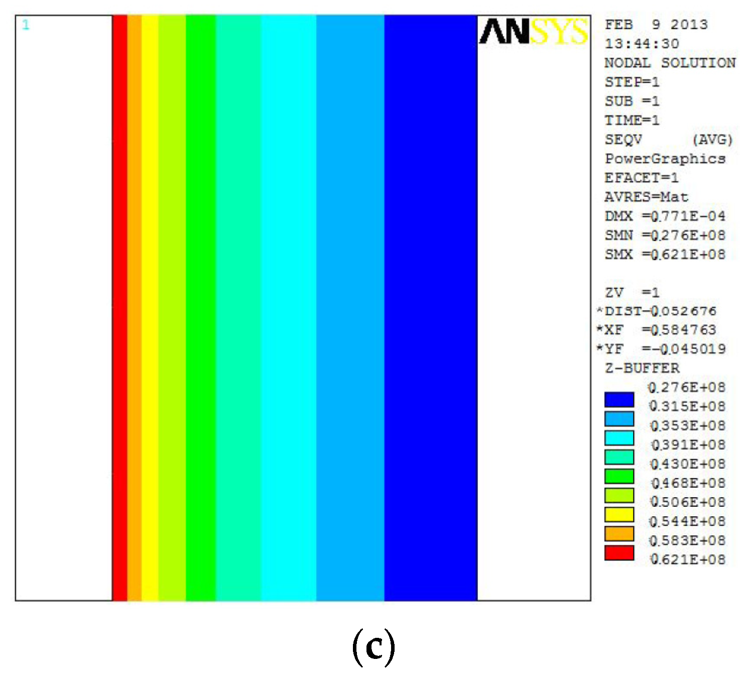
- The variations of tangential stresses decrease gradually at the outer surface and increase very little at the inner surface with increasing rotational velocity .
- The tangential stresses are also higher at the inner surface than those at the outer surface.
- Tangential stresses attained nearly constant values in the radial direction of the cylinder for = 300 rad/sec and low rotational velocities.
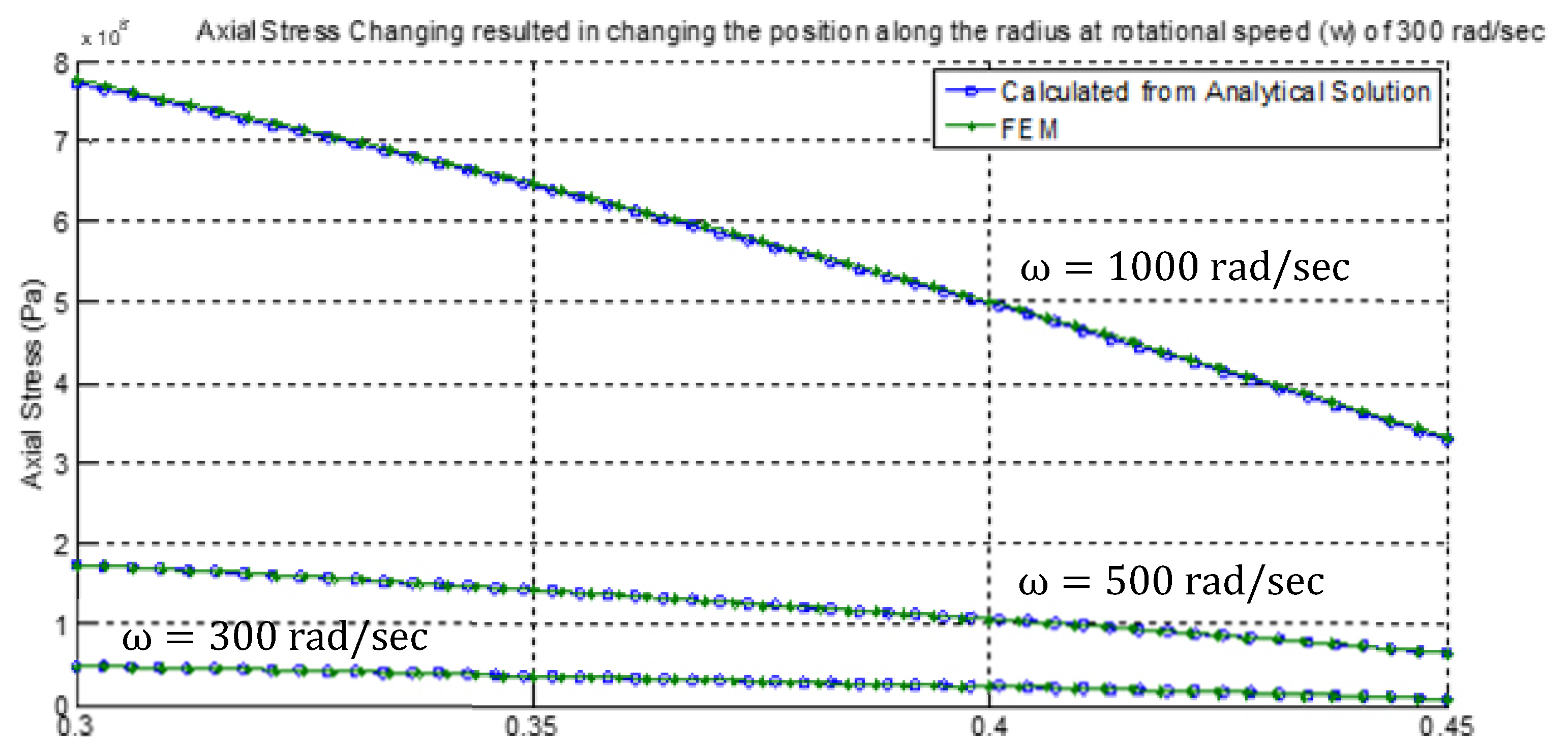
- Variations of Axial stresses have the same behavior as tangential stresses .
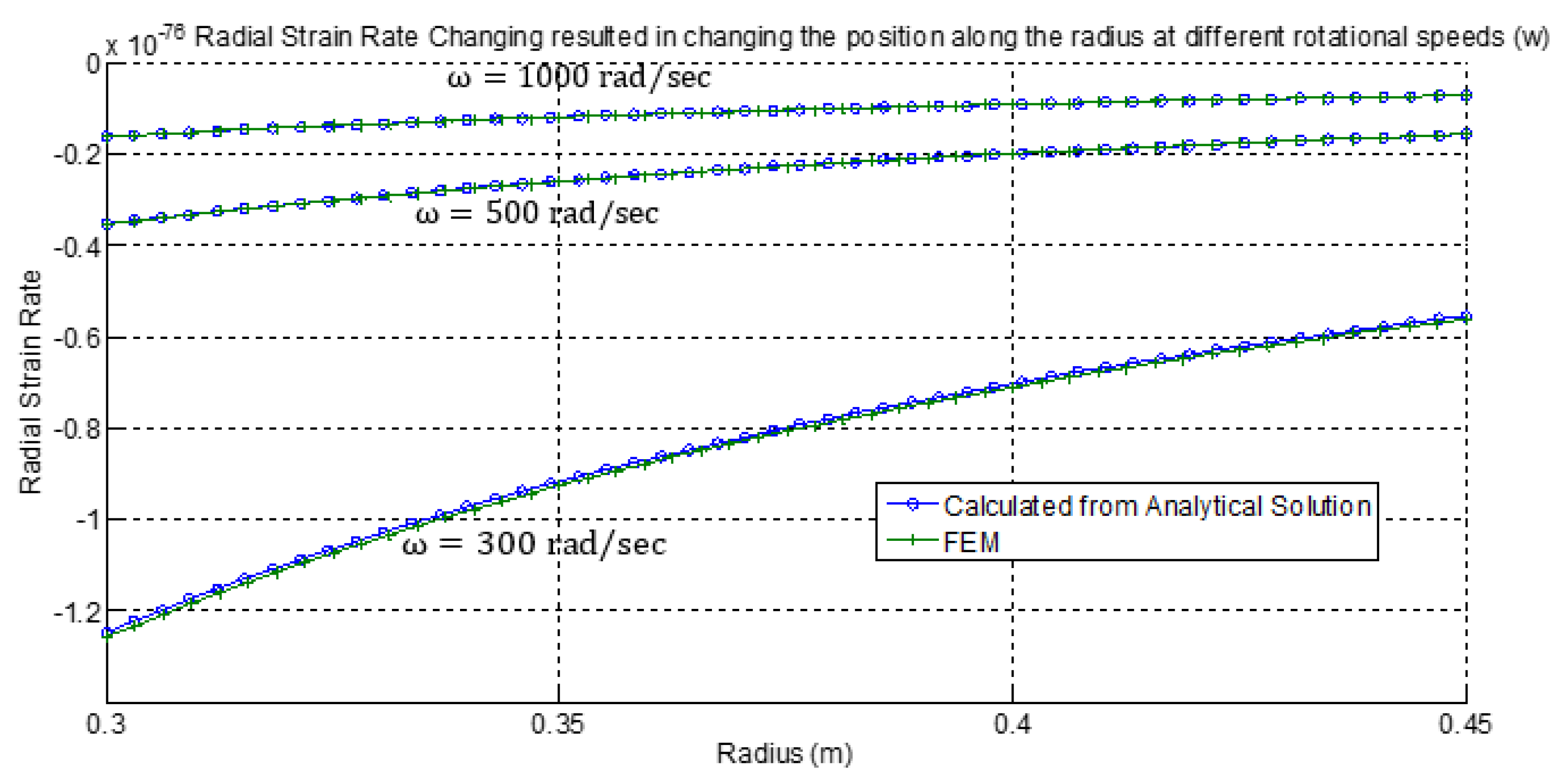
- All radial strain rate values are higher (in magnitude) at the inner surface and vary with parallel curves in the radial direction of the cylinder.
- All radial strain rates decrease gradually with an increase in the rotational velocity.
- All tangential strain rates and equivalent creep strain rates have the same behavior as radial strain rates.
Author Contributions
Funding
Institutional Review Board Statement
Informed Consent Statement
Data Availability Statement
Conflicts of Interest
Nomenclature
| FEA/M | Finite Element Analysis/Method |
| FGM | Functionally Graded Material |
| (Si-C) | Silicon Carbide |
| Al-SiCp | Aluminum Silicon Carbide composite |
| Inner radius | |
| Outer radius | |
| Internal pressure | |
| External pressure | |
| Material density | |
| ras/sec | Angular/Rotational velocity |
| Radial stress | |
| ) | Tangential stress |
| Axial stress | |
| Radial strain rate | |
| Tangential strain rate | |
| Axial strain rate | |
| effective stress | |
| Effective strain rate | |
| and | Creep materials constants |
| Radial displacement | |
| and | Boundary constants |
References
- Arya, V. Large strain creep analysis of composite thick-walled anisotropic cylinders. J. Mech. Eng. Sci. 2023, 17, 9395–9409. [Google Scholar] [CrossRef]
- Bhatta, L.; Pesin, A.; Zhilyaev, A.P.; Tandon, P.; Kong, C.; Yu, H. Recent Development of Superplasticity in Aluminum Alloys: A Review. Metals 2020, 10, 77. [Google Scholar] [CrossRef]
- Zheng, J.-H.; Jin, Y.; Xu, L.; Fan, C.; Song, W.; Chen, Y. Comparative Study of Creep and Stress Relaxation Behaviour during Ageing of 7050 Aluminum Alloy. Metals 2023, 13, 778. [Google Scholar] [CrossRef]
- Abdulsahib, A.D.; Al-Farhany, K. Review of the Effects of Stationary/Rotating Cylinder in a Cavity on the Convection Heat Transfer in Porous Media with/without Nanofluid. Math. Model. Eng. Probl. 2021, 8, 356–364. [Google Scholar] [CrossRef]
- Lao, S.; Zhan, L.; Qian, W.; Xu, Y.; Ma, B.; Liu, C.; Huang, M.; Yang, Y.; Chen, K.; Peng, N.; et al. Creep Aging Behavior of a Thermo-Mechanical Treated 7B04 Aluminum Alloy. Metals 2023, 13, 182. [Google Scholar] [CrossRef]
- Azeem, M.; Ya, H.H.; Alam, M.A.; Kumar, M.; Stabla, P.; Smolnicki, M.; Gemi, L.; Khan, R.; Ahmed, T.; Ma, Q.; et al. Application of Filament Winding Technology in Composite Pressure Vessels and Challenges: A Review. J. Energy Storage 2022, 49, 103468. [Google Scholar] [CrossRef]
- Jayaraman, P.; Pandey, A. Mechanical Design and Analysis of CNT Modified Carbon Fibre Composite Pressure Vessel. In Proceedings of the AIAA AVIATION 2022 Forum, Chicago, IL, USA, 27 June–1 July 2022. [Google Scholar]
- Heugue, P.; Larouche, D.; Breton, F.; Martinez, R.; Chen, X.-G.; Massinon, D. Modelling of Strain-Controlled Thermome-chanical Fatigue Testing of Cast AlSi7Cu3.5Mg0.15 (Mn, Zr, V) Alloy for Different Aging Conditions. Metals 2022, 12, 1258. [Google Scholar] [CrossRef]
- Smaisim, G.F.; Bidgoli, M.O.; Goh, K.L.; Bakhtiari, H. Review of thermoelastic, thermal properties and creep analysis of functionally graded cylindrical shell. Aust. J. Mech. Eng. 2022, 1–12. [Google Scholar] [CrossRef]
- Orozco-Caballero, A.; Álvarez-Leal, M.; Carreño, F.; Ruano, O.A. Superplastic Behavior of Overaged 2024 Aluminum Alloy after Friction Stir Processing. Metals 2022, 12, 1880. [Google Scholar] [CrossRef]
- Qiao, K.; Zhu, A.; Wang, B.; Di, C.; Yu, J.; Zhu, B. Characteristics of Heat Resistant Aluminum Alloy Composite Core Conductor Used in overhead Power Transmission Lines. Materials 2020, 13, 1592. [Google Scholar] [CrossRef]
- Sahni, M.; Mehta, P.D.; Sahni, R.; León-Castro, E.; Espinoza-Audelo, L.F. Secondary Creep Analysis of FG Rotating Cylinder with Exponential, Linear and Quadratic Volume Reinforcement. Materials 2022, 15, 1803. [Google Scholar] [CrossRef] [PubMed]
- Zhang, X.-C.; Gong, J.-G.; Xuan, F.-Z. A deep learning based life prediction method for components under creep, fatigue and creep-fatigue conditions. Int. J. Fatigue 2021, 148, 106236. [Google Scholar] [CrossRef]
- Almeida, J.H.S.; Lisbôa, T.V.; Spickenheuer, A.; St-Pierre, L. A sequential finite element model updating routine to identify creep parameters for filament wound composite cylinders in aggressive environments. Comput. Struct. 2023, 276, 106939. [Google Scholar] [CrossRef]
- Liu, Y.; Wang, Y.; Wei, D.; Jiang, X.; Tao, Q. Modeling of Creep Deformation Behavior of DZ411 and Finite Element Simulation of Turbine Blade. Metals 2023, 13, 1389. [Google Scholar] [CrossRef]
- Katouzian, M.; Vlase, S.; Scutaru, M.L. Finite Element Method-Based Simulation Creep Behavior of Viscoelastic Carbon-Fiber Composite. Polymers 2021, 13, 1017. [Google Scholar] [CrossRef]
- Bansal, S.; Singh, S.B. Steady-State Creep Deformation In Rotating Discs And Cylinders: For Macro To Micro/Nano-Scale Systems. In Nanotechnology-Enhanced Solid Materials: Design, Synthesis, Properties, Applications, and Perspectives; Apple Academic Press: Cambridge, MA, USA, 2023; p. 259. [Google Scholar] [CrossRef]
- Bansal, S.; Singh, S.; Haghi, A. Investigations of Flow Behavior in Cylinder and Disc Made of Monolithic and Composite Materials. In Materials Modeling for Macro to Micro/Nano Scale Systems; Apple Academic Press: Cambridge, MA, USA, 2022; pp. 269–306. [Google Scholar]
- Arya, V.K. Effect of anisotropy on the large strain creep behavior of composite thick-walled spherical vessels. J. Braz. Soc. Mech. Sci. Eng. 2022, 44, 473. [Google Scholar] [CrossRef]
- Madani, K.; Houari, A.; Bouchikhi, A.; Mokhtari, M. Numerical analysis of the elastic-plastic behavior of a tubular structure in FGM under pressure and defect presence. Frat. Ed Integrità Strutt. 2022, 16, 212–231. [Google Scholar] [CrossRef]
- Lei, C.; Li, H.; Fu, J.; Shi, N.; Zheng, G.; Bian, T. Damage in Creep Aging Process of an Al-Zn-Mg-Cu Alloy: Experiments and Modeling. Metals 2018, 8, 285. [Google Scholar] [CrossRef]
- Rakhmonov, J.U.; Bahl, S.; Shyam, A.; Dunand, D.C. Cavitation-resistant intergranular precipitates enhance creep performance of θ′-strengthened Al-Cu based alloys. Acta Mater. 2022, 228, 117788. [Google Scholar] [CrossRef]
- Michi, R.A.; Sisco, K.; Bahl, S.; Yang, Y.; Poplawsky, J.D.; Allard, L.F.; Dehoff, R.R.; Plotkowski, A.; Shyam, A. A creep-resistant additively manufactured Al-Ce-Ni-Mn alloy. Acta Mater. 2022, 227, 117699. [Google Scholar] [CrossRef]
- Yang, Q.; Yan, Z.; Lv, S.; Guan, K.; Qiu, X. Abnormal creep stress exponents in a high-pressure die casting Mg–Al−RE alloy. Mater. Sci. Eng. A 2022, 831, 142203. [Google Scholar] [CrossRef]
- Frankberg, E.J.; Lambai, A.; Zhang, J.; Kalikka, J.; Khakalo, S.; Paladino, B.; Cabrioli, M.; Mathews, N.G.; Salminen, T.; Hokka, M.; et al. Exceptional Microscale Plasticity in Amorphous Aluminum Oxide at Room Temperature. Adv. Mater. 2023, 142, e2303142. [Google Scholar] [CrossRef] [PubMed]
- Zhang, M.; Lewis, R.; Gibeling, J. Mechanisms of creep deformation in a rapidly solidified Al–Fe–V–Si alloy. Mater. Sci. Eng. A 2021, 805, 140796. [Google Scholar] [CrossRef]
- Manjunath, R.; Kumar, D.; Kumar, A. A Review on the Significance of Hybrid Particulate Reinforcements on the Mechanical and Tribological Properties of Stir-Casted Aluminum Metal Matrix Composites. J. Bio-Tribo-Corros. 2021, 7, 122. [Google Scholar] [CrossRef]
- Sohag, A.Z.; Gupta, P.; Kondal, N.; Kumar, D.; Singh, N.; Jamwal, A. Effect of ceramic reinforcement on the microstructural, mechanical and tribological behavior of Al-Cu alloy metal matrix composite. Mater. Today Proc. 2020, 21, 1407–1411. [Google Scholar] [CrossRef]
- Singh, L.; Kumar, S.; Raj, S.; Shivam; Badhani, P. Development and characterization of aluminium silicon carbide composite materials with improved properties. Mater. Today Proc. 2021, 46, 6733–6736. [Google Scholar] [CrossRef]
- Arya, R.K.; Kumar, R.; Telang, A. Influence of Microstructure on Tribological Behaviors of Al6061 Metal Matrix Composite Reinforced with Silicon Nitride (Si3N4) and Silicon Carbide (SiC) Micro Particles. Silicon 2023, 15, 3987–4001. [Google Scholar] [CrossRef]
- Gouda, S.; Gouda, S.; Kumar, G.B.V.; Kumar, G.B.V.; Pramod, R.; Pramod, R.; Prasanna, N.D.; Prasanna, N.D.; Balasubramanya, H.S.; Balasubramanya, H.S.; et al. Fabrication, Mechanical and Wear Properties of Aluminum (Al6061)-Silicon Carbide-Graphite Hybrid Metal Matrix Composites. Frat. Ed Integrità Strutt. 2022, 16, 134–149. [Google Scholar] [CrossRef]
- Ziaei-Asl, A.; Saviz, M.R.; Pourabdollah, J. Creep and Stress Redistribution Analysis of Thick-Wall FGM Spheres Subjected to Mechanical Load and Heat Flux–An Analytical Approach. J. Adv. Mater. Process. 2020, 8, 53–64. [Google Scholar]
- Temesgen, A.G.; Singh, S.B.; Pankaj, T. Modeling of Creep Deformation in an Internally Pressurized Transversely Isotropic Spherical Shell Subjected to a Thermal Gradient. Mech. Solids 2022, 57, 937–948. [Google Scholar] [CrossRef]
- Zhang, N.; Lu, A.; Li, C.C.; Zhou, J.; Zhang, X.; Wang, S.; Chen, X.; Mohammadi, M.; Saha, G.; Akbarzadeh, A.; et al. Optimal Design of Functionally Graded Incompressible Linear Elastic Cylinders and Spheres. AIAA J. 2008, 46, 2050–2057. [Google Scholar] [CrossRef]
- Benslimane, A.; Benchallal, R.; Mammeri, S.; Methia, M.; Khadimallah, M.A. Investigation of displacements and stresses in thick-walled FGM cylinder subjected to thermo-mechanical loadings. Int. J. Comput. Methods Eng. Sci. Mech. 2020, 22, 138–149. [Google Scholar] [CrossRef]
- Gupta, V.; Kumar, V.; Ray, S. Modeling creep in a rotating disc with linear and quadratic composition gradients. Eng. Comput. 2009, 26, 400–421. [Google Scholar] [CrossRef]
- Nie, G.; Zhong, Z.; Batra, R. Material tailoring for functionally graded hollow cylinders and spheres. Compos. Sci. Technol. 2011, 71, 666–673. [Google Scholar] [CrossRef]
- Ansys®. Academic Research Mechanical, Release 18.1, Help System, Coupled Field Analysis Guide, Help System, Mechanical APDL, Theory Reference; ANSYS, Inc.: Canonsburg, PA, USA; Available online: https://www.ansys.com/academic/terms-and-conditions (accessed on 9 February 2013).
- Jin-Feng, Z.; Wang, F.; Wei, A. A semi-analytical solution for shallow tunnels with radius-iterative-approach in semi-infinite space. Appl. Math. Model. 2019, 73, 285–302. [Google Scholar] [CrossRef]
- Feng, G.; Zhu, C.; Wang, X.; Tang, S. Thermal effects on prediction accuracy of dense granite mechanical behaviors using modified maximum tangential stress criterion. J. Rock Mech. Geotech. Eng. 2023, 15, 1734–1748. [Google Scholar] [CrossRef]
- Lyu, F.; Li, Y.; Huang, X.; Shi, Z.; Zeng, Y.; Lin, J. An investigation of creep age forming of AA7B04 stiffened plates: Experiment and FE modelling. J. Manuf. Process. 2019, 37, 232–241. [Google Scholar] [CrossRef]
- Eggers, F.; Almeida Jr, J.H.S.; Lisbôa, T.V.; Amico, S.C. Creep and Residual Properties of Filament-Wound Composite Rings under Radial Compression in Harsh Environments. Polymers 2020, 13, 33. [Google Scholar] [CrossRef]
- Dharmendra, C.; Rao, K.P.; Suresh, K.; Hort, N. Hot Deformation Behavior and Processing Map of Mg-3Sn-2Ca-0.4Al-0.4Zn Alloy. Metals 2018, 8, 216. [Google Scholar] [CrossRef]


Disclaimer/Publisher’s Note: The statements, opinions and data contained in all publications are solely those of the individual author(s) and contributor(s) and not of MDPI and/or the editor(s). MDPI and/or the editor(s) disclaim responsibility for any injury to people or property resulting from any ideas, methods, instructions or products referred to in the content. |
© 2023 by the authors. Licensee MDPI, Basel, Switzerland. This article is an open access article distributed under the terms and conditions of the Creative Commons Attribution (CC BY) license (https://creativecommons.org/licenses/by/4.0/).
Share and Cite
Es-Saheb, M.H.; Fouad, Y. Creep Analysis of Rotating Thick Cylinders Subjected to External and Internal Pressure: Analytical and Numerical Approach. Appl. Sci. 2023, 13, 11652. https://doi.org/10.3390/app132111652
Es-Saheb MH, Fouad Y. Creep Analysis of Rotating Thick Cylinders Subjected to External and Internal Pressure: Analytical and Numerical Approach. Applied Sciences. 2023; 13(21):11652. https://doi.org/10.3390/app132111652
Chicago/Turabian StyleEs-Saheb, Mahir H., and Yasser Fouad. 2023. "Creep Analysis of Rotating Thick Cylinders Subjected to External and Internal Pressure: Analytical and Numerical Approach" Applied Sciences 13, no. 21: 11652. https://doi.org/10.3390/app132111652