Article

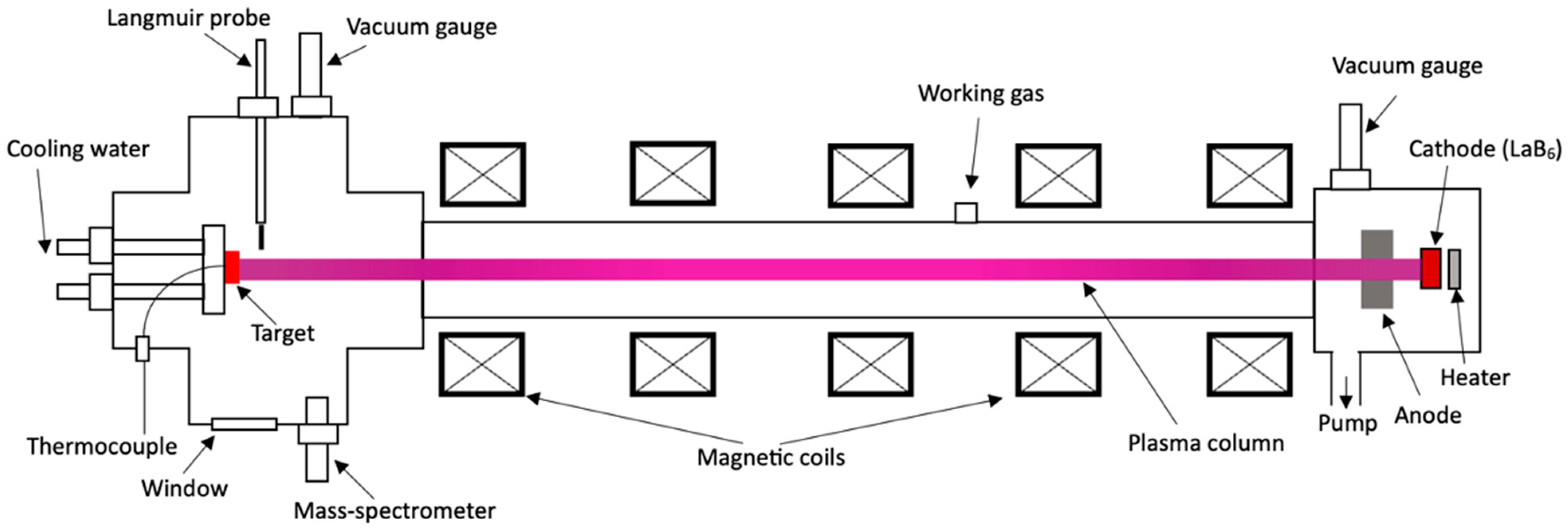
Linear Plasma Device for the Study of Plasma–Surface Interactions

by
Bauyrzhan Rakhadilov
1,
Zarina Satbayeva
1,*,
Arystanbek Kusainov
1,
Erasyl Naimankumaruly
1,
Riza Abylkalykova
2 and
Laila Sulyubayeva
2
1
“PlasmaScience” LLP, Ust-Kamenogorsk 070000, Kazakhstan
2
Research Center “Surface Engineering and Tribology”, S. Amanzholov East Kazakhstan University, Ust-Kamenogorsk 070000, Kazakhstan
*
Author to whom correspondence should be addressed.
Appl. Sci. 2023, 13(21), 11673; https://doi.org/10.3390/app132111673
Submission received: 27 September 2023 / Revised: 20 October 2023 / Accepted: 23 October 2023 / Published: 25 October 2023

Abstract

:
At the research and production company “PlasmaScience” (Ust-Kamenogorsk, Kazakhstan), a linear plasma generator installation, KAZ-PSI (Kazakhstan Plasma Generator for Plasma Surface Interactions), has been developed and constructed for the study of the interaction of plasma and materials. This article outlines some features of the developed experimental installation designed for the investigation of surface–plasma interactions. The primary components of the linear plasma installation include an electron-beam gun with a LaB6 cathode, a plasma-beam discharge chamber, an interaction chamber, a target device, and an electromagnetic system comprising electromagnetic coils. The KAZ-PSI unit enables continuous plasma generation using hydrogen, deuterium, helium, argon, and nitrogen. The electron density of the plasma is in the range of about 1017–1018 m−3 and the electron temperature is in the range of 1 to 20 eV. The incident ion energy is regulated by applying a negative potential of up to 2 kV to the target. Experiments on the irradiation of tungsten with helium plasma were carried out using the KAZ-PSI installation for the first time. This article presents the research findings on the structure and properties of tungsten relative to the temperature of helium plasma irradiation. Alterations in roughness, microstructure, hardness, modulus of elasticity, and erosion of the tungsten’s surface following helium plasma irradiation at varying temperatures were examined. The study’s results indicate that helium plasma irradiation induces changes in the morphology of the tungsten’s surface, creating surface relief due to sputtering by helium ions, as well as the formation of blisters. Mechanical testing revealed that after irradiation at T = 500 °C, there was an increase in hardness of up to 10%, and a slight decrease in modulus of elasticity. And after irradiation at T = 900 °C and T = 1300 °C, both hardness and elastic modulus decreased with rising temperature. The tungsten surface erosion evaluation results showed that the degrees of surface erosion increase with increasing target temperature.

1. Introduction

The plasma-facing material (PFM) serves as the primary interface between the fusion plasma and the reactor structure, making it highly susceptible to severe irradiation conditions [1]. This susceptibility could constrain the availability of a fusion device utilizing magnetic confinement, such as the International Thermonuclear Experimental Reactor (ITER). Tungsten (W) is the primary material employed in the ITER divertor [2]. Additionally, producers of next-generation devices like the China Fusion Engineering Test Reactor (CFETR) [3] are considering the utilization of a fully tungsten first-wall, owing to its distinct advantages, which include high thermal conductivity, a high melting point, low tritium retention, and a low erosion rate [4]. Nevertheless, tungsten’s brittleness poses a limitation as a PFM, leading to challenges in component manufacturing and the potential for operational failure at elevated temperatures and under high thermal loads [5]. Critical factors influencing tungsten’s performance encompass mechanical properties such as plasticity and the ductile-to-brittle transition temperature (DBTT) [5].
Furthermore, severe irradiation conditions, including the impact of high-flux particles, thermal loads, and neutron damage, degrade the mechanical properties of W and increase its DBTT [6]. Advanced materials, based on W, with high operational characteristics that can maintain their structure even under severe irradiation conditions are needed [7]. Therefore, the study of plasma–surface interaction characteristics is a key focus of modern thermonuclear research, as it directly affects the performance, lifespan, and safety of future thermonuclear power installations. Linear plasma generators make a significant contribution to these studies, as they enable the systematic solution of complex physical problems related to plasma–wall interaction, have controllable plasma parameters and flexible target geometries, and provide good diagnostic access [8,9,10]. Linear plasma generators are highly effective tools for testing candidate materials for fusion reactors, and for contributing to the database on various aspects of plasma–surface interaction [11]. Interest in simulating the interactions of plasma and fusion reactor materials within simulations of gas discharge using plasma generators emerged in the last century, in the early nineteen-eighties. Ion beam facilities have already provided fundamental insights into elementary processes occurring when ions interact with the surface of a solid material, such as material sputtering, capture, and reflection of particles. With the commissioning of the full-scale ITER tokamak reactor, where all damaging factors will be thoroughly combined, the emergence of new synergistic phenomena and effects can be expected. The study of these phenomena can heavily rely on the database and physical models developed in simulation experiments.
Among linear plasma generators, linear plasma installations with plasma generation controlled by an electron beam [12,13,14] have certain advantages as devices that allow the combination of plasma impacts and electron beams in tests with high thermal flux. In connection with this, a new laboratory linear plasma installation, KAZ-PSI, was developed and built for testing divertor candidate materials and conducting research on plasma–surface interactions.
This study aims to assess the experimental capabilities of the developed linear plasma installation KAZ-PSI, and to investigate the irradiation of tungsten with helium plasma using this installation.

2. Materials and Methods

The developed experimental plasma installation, KAZ-PSI, is versatile and allows for materials testing under the combined influence of both plasma flux and high thermal loads generated by an electron beam. The use of this plasma installation provides the capability to promptly obtain preliminary experimental data on the behavior of materials under conditions associated with their interaction with plasma at high thermal loads [15]. The overall appearance of the linear plasma installation KAZ-PSI is shown in Figure 1a.
The main elements of the plasma installation shown in Figure 1b consist of a plasma-beam discharge chamber, an interaction chamber, an electron-beam gun, a target assembly, and a system of magnetic coils. The electron-beam gun consists of a cylindrical cathode (LaB6) and an anode ring, separated by a ceramic insulator. The cathode is heated in a resistive way, with a constant current source providing up to 25 kW of power. The vacuum chamber consists of a discharge chamber and an interaction chamber. The discharge chamber is made in the form of a narrow cylinder 1 m long and 0.15 m in diameter. The interaction chamber is designed as a complex assembly with six ISO160 flanges. The target assembly contains a holder in which retaining elements in the form of spouts are installed to place the target in them. The target holder is a hollow cylinder with a diameter of 80 mm which has pipe connections for water cooling.
The vacuum pumping system comprises a backing pump and a turbomolecular pump, and is capable of maintaining residual gas pressure in the chamber at a level of 5·10−8 Pa. The typical base working pressure is on the order of 5·10−4–5·10−5 Pa. The gas injection system consists of vacuum-leak valves designed to introduce gas into the vacuum chamber with a controlled flow rate within a strictly specified small range, allowing for smooth adjustment.
The power supply system encompasses power units for electromagnetic coils, vacuum pumping means, diagnostics, cooling, parameter monitoring, and the source providing negative potential to the target. It also includes a complex set of power supplies for the electron beam gun, comprising a DC power supply for the heater unit and an adjustable high-voltage unit for shaping the primary beam of the plasma-beam discharge. The diagnostic system comprises a quadrupole mass spectrometer, a Langmuir probe, and pyrometers. The control system incorporates computer programs for remote control of the installation components.
In Figure 2, a schematic representation of the linear plasma installation KAZ-PSI is depicted. The operation of the plasma installation unfolds as follows. The electron gun forms an axially symmetric electron beam. The gun’s cathode is heated using a tungsten filament. The cathode heating power regulates the power of the gun. Upon the introduction of the working gas into the discharge chamber, the electron beam interacts with the working gas, giving rise to a plasma-beam discharge.
The working gases employed include hydrogen, deuterium, helium, and others. The focusing of the plasma beam is achieved through the use of electromagnetic coils which generate a longitudinal magnetic field in the discharge chamber. The magnetic field strength is adjusted by varying the electric current flowing through the electromagnetic coils. The plasma beam impinges upon the target (test material) positioned in the plasma receptacle located within the interaction chamber. To ensure a high ion concentration and attain the maximum power of the plasma flow without disruptions, a negative accelerating potential of up to 2 kV is applied to the target using the PCH6000-20H power supply.
The Langmuir probe is used to determine the parameters of the plasma flow. An electric conductor is placed in the plasma, depending on its potential [16]. The probe method of diagnostics is based on active probing of the plasma under study with a current of low intensity. During diagnostics, a probe is placed in the plasma and discrete step voltage pulses are applied to it. Then, registering the volt–ampere characteristics, the plasma space potential is measured [16]. The environment in the interaction chamber is monitored using an XT-100 quadrupole mass spectrometer produced by “Extorr Inc” (Columbia, New Kensington, USA). The key parameters of the plasma in the KAZ-PSI installation are provided in Table 1.
Currently, several linear plasma generators are being used to simulate the peripheral plasma of tokamaks and nuclear fusion reactors. However, widely recognized and frequently cited results have primarily been obtained from the following installations: PSI-2 [17], STEP [18], PISCES-B [19], PREFACE [20], VEHICLE-1 [21], NAGDIS-II [22], Pilot-PSI [23], Magnum-PSI [24,25], and PSIEC [26]. Table 2 provides the technical specifications of these linear plasma generators, and the key characteristics of the KAZ-PSI installation are compared with the characteristics of existing linear plasma devices.
From the analysis of Table 2, it can be concluded that our developed KAZ-PSI installation is competitive with many of its foreign counterparts in terms of various characteristics. Moreover, it fully meets the requirements for a simulation modeling the interaction between plasma and materials in a nuclear fusion reactor.

3. Experimental Procedure

Before irradiation, tungsten samples of 99.95% purity in the form of cylinders with a diameter of 6.3 mm and a height of 5 mm were ground and polished. During irradiation of tungsten with helium plasma, the pressure in the interaction chamber was 5·10−4 Torr. The tungsten samples were exposed to helium plasma at T = 500 °C, T = 900 °C, and T = 1300 °C. The duration of irradiation was 1 h.
The characteristics of the microstructure were determined using a scanning electron microscope (SEM) JSM-6390 (Jeol, Tokyo, Japan) combined with an energy-dispersive spectrometer (EDS) Oxford INCAEnergy (Oxford Instrument, Abingdon, UK). X-ray structural analysis was performed using the X’PertPRO X-ray diffractometer (Almelo, Netherlands) with Cu Kα radiation. The diffractometer was calibrated using the Si standard. Surface roughness was measured using the Precise Roughness Tester HY 230 profilometer. Surface erosion after irradiation was assessed by weighing the samples before and after irradiation using analytical scales designated VL-224V. To determine hardness and modulus of elasticity during indentation, a microhardness tester (Fischerscope HM2000 by Helmut Fischer GmbH, Sindelfingen, Germany) was used. This instrument performs instrumental indentation testing following DIN EN ISO 14577-1. The loading rate was 2 μm/s, and the applied load was 1.96 N. The results of the tests were initially processed using the WIN-HCU 7.1 instrument software. A Vickers diamond pyramid indenter with an angle of 136° was used.

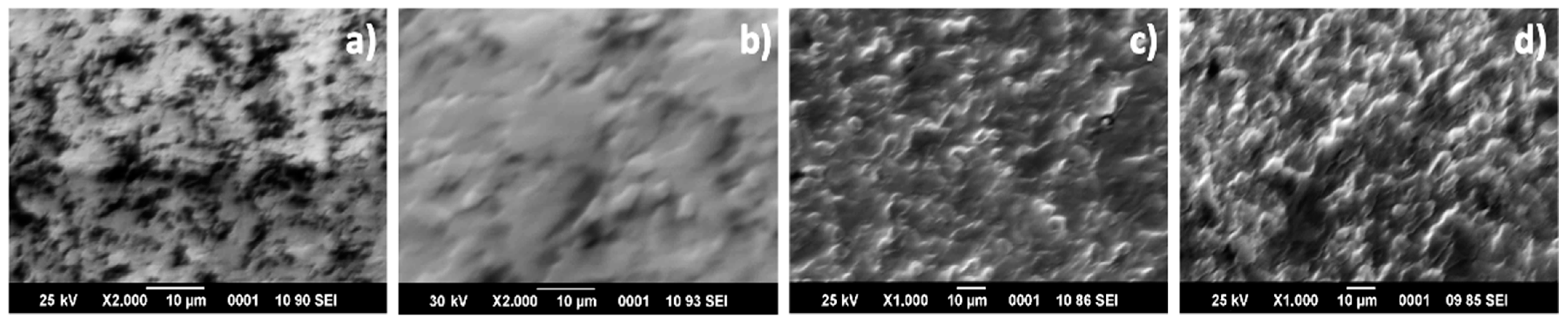
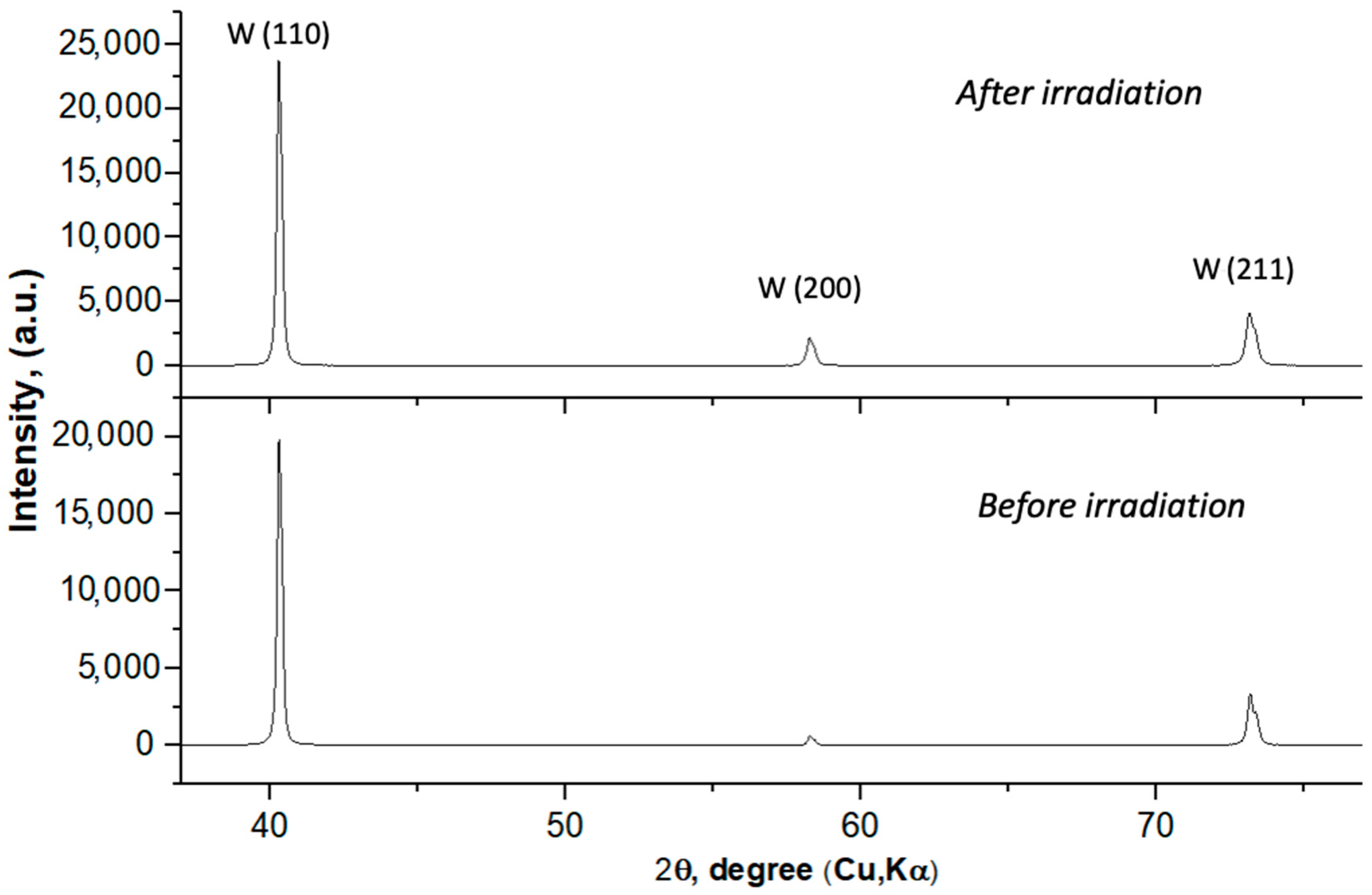
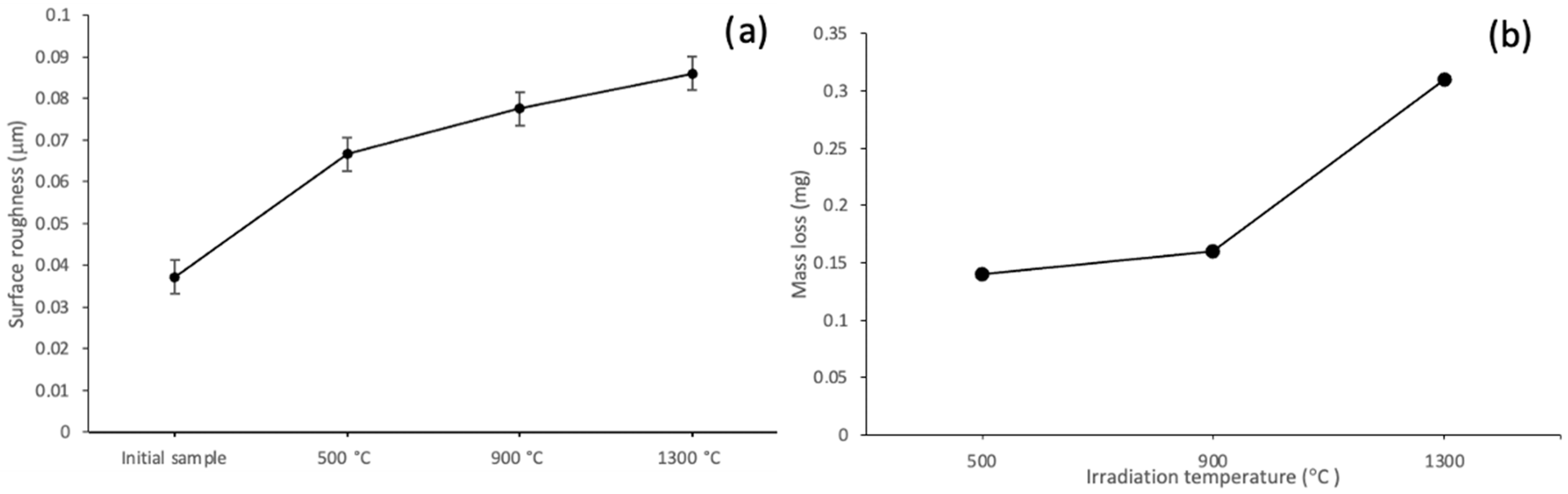
4. Results and Discussion

In Figure 3, SEM images of tungsten samples before (Figure 3a) and after exposure to helium plasma at temperatures of T = 500 °C (Figure 3b), T = 900 °C (Figure 3c), and T = 1300 °C (Figure 3d) are presented. The research results indicate that exposure to helium plasma leads to changes in the surface morphology of tungsten. Relief areas are formed on the surface due to the sputtering by helium ions, as well as the accumulation of helium ions in the near-surface layer, which leads to the formation of blisters. In the case of tungsten samples irradiated at T = 500 °C (Figure 3b), etching areas are observed on the surface due to the sputtering by helium ions. For tungsten samples irradiated at T = 900 °C and T = 1300 °C, a highly relieved morphology forms on the surface. Blisters and eroded areas on the surface can be observed. The formation of blisters is attributed to the creation of high-pressure regions within the lattice due to the accumulation of helium atoms, causing localized expansion of the material and resulting in blister formation on the surface.
The X-ray structural phase analysis showed that there is no change in the phase composition of tungsten after exposure to helium plasma (Figure 4). From the diffractogram, we can observe a change in the shape of the diffraction peaks. Broadening of the diffraction peaks (110) and (211) is observed on the diffractogram. This indicates the emergence of mechanical stresses after exposure at T = 1300 °C. Mechanical stresses in tungsten during exposure to helium plasma can arise due to several factors. When helium ions are implanted into the material, they can create lattice defects such as vacancies and interstitials. Accumulation of these defects can lead to the generation of internal stresses in the material. Additionally, this may be associated with the formation of bubbles. Helium ions have a high affinity for forming helium bubbles (or voids) within the material as they accumulate. These bubbles can exert pressure on the surrounding material, leading to swelling and the emergence of mechanical stresses.
The hardness and elastic modulus of the tungsten samples were measured before and after irradiation with helium plasma (Figure 5). After irradiation at T = 500 °C, an increase in hardness by 10% and a slight decrease in elastic modulus was observed. The increase in hardness may be attributed to the development of mechanical stress due to helium accumulation in the near-surface layer of tungsten. It is known that the accumulation of helium in the near-surface layer leads to compressive stresses which reduce the elastic modulus and increase the hardness of the metal. After irradiation at T = 900 °C and T = 1300 °C, hardness and elastic modulus decrease depending on the temperature. This might be associated with structural changes, increased roughness, and an increase in the volume fraction of voids.
The erosion of tungsten samples was assessed by weighing the samples before and after irradiation. Surface roughness was also evaluated. Figure 6a shows the dependence of surface roughness and mass loss of tungsten on the irradiation temperature of helium plasma. From Figure 6a, it can be observed that surface roughness increases after irradiation. The increase in roughness is associated with surface sputtering by helium ions, as well as the formation of blisters. The graph indicates that the surface roughness of tungsten increases with increasing irradiation temperature. As revealed by microstructural analysis, defects such as etching pits and blisters increase with temperature. These changes are reflected in the surface roughness. At the same time, the primary role in changing the relief is played by the sputtering of the surface with helium ions. It is known that in the case of irradiation of metals and alloys with ions and plasma of inert gases at temperatures above the annealing temperature of elementary defects created by irradiation, the formation of reliefs occurs primarily due to surface sputtering, due to the kinetic energy of ions arising through a cascade mechanism.
The assessment of surface erosion rate based on the loss of sample mass during irradiation is a commonly used technique in materials science. In this study, the weights of the samples were measured before and after irradiation, and the dependencies of the mass losses of the samples on the irradiation temperatures were obtained (Figure 6b). From Figure 6b, it is evident that the mass loss of tungsten increases with the rise in irradiation temperature. Moreover, the mass loss is negligible after irradiation at 500 °C and 900 °C. The degree of erosion increases after irradiation at 1300 °C, which is entirely expected. At high temperatures, tungsten atoms in the target undergo more thermal vibrations, making them more mobile. This increased mobility can influence the sputter yield and the behavior of sputtered atoms.
The surface roughness of the coatings’ Ra was evaluated using a profilometer, model 130 (JSC “Plant PROTON”, Moscow, Russia). The Ra value, which represents the arithmetical mean deviation of the profile, was chosen as the main parameter for evaluating the coatings’ surface roughness. The obtained results have shown that as the target temperature increases, the degree of surface erosion also increases. However, within the studied temperature range, the degree of tungsten surface erosion is insignificant. Due to its thermophysical properties, noticeable erosion of tungsten from plasma exposure simulating steady-state plasma conditions only occurs at higher irradiation temperatures.

5. Conclusions

Based on analysis of the literature and the experimental results, it can be stated that the developed experimental plasma installation KAZ-PSI is not inferior to many foreign analogs and fully complies with the requirements of simulations modeling the interaction of plasma and the materials of a fusion reactor. Studying plasma–surface interactions using a simulated plasma installation creates the possibility of justifying the selection of materials for the energetic fusion reactor, expanding the database of various aspects of plasma–surface interaction, verifying computational models, refining diagnostic techniques, etc. Therefore, the creation of simulation-plasma installations for studying the materials of fusion reactors holds paramount importance. These installations, by simulating plasma, enable scientists to replicate and study these conditions on a smaller scale, providing insights into how materials will behave in a real fusion reactor.
The experiments conducted to investigate the changes in the microstructure of tungsten revealed that after exposure to helium plasma, the surface morphology of tungsten is changed. A relief is formed on the surface due to the sputtering by helium ions, as well as the accumulation of helium ions in the near-surface layer, leading to the formation of blisters. In the case of tungsten samples irradiated at 500 °C, regions of etching are observed on the surface due to the sputtering by helium ions. Meanwhile, in samples irradiated at 900 °C and 1300 °C, a significant high-relief morphology is formed on the surface, which is attributable to the blister formation and the appearance of eroded areas caused by sputtering. The formation of blisters is attributed to the creation of high-pressure regions in the lattice due to the accumulation of helium atoms, resulting in local expansions of the material and the formation of blisters on its surface. X-ray structural analysis confirmed the occurrence of mechanical stresses in tungsten after exposure to helium plasma. The results of mechanical tests showed that after irradiation at 500 °C, there is an increase in hardness of up to 10% and a slight decrease in elastic modulus. However, after irradiation at 900 °C and 1300 °C, both hardness and elastic modulus decrease, depending on the temperature. The results of the surface-erosion assessment for tungsten indicated that the degree of surface erosion increases with higher irradiation temperatures.

Author Contributions

Conceptualization, B.R.; methodology, B.R.; investigation, Z.S., A.K. and E.N.; data curation, R.A. and L.S.; writing—original draft preparation, B.R., A.K. and E.N.; writing—review and editing, B.R., Z.S., R.A. and L.S.; supervision, B.R.; project administration, B.R. All authors have read and agreed to the published version of the manuscript.

Funding

This research has been funded by the Science Committee of the Ministry of Science and Higher Education of the Republic of Kazakhstan (Grant no. AP09058568).

Institutional Review Board Statement

Not applicable.

Informed Consent Statement

Not applicable.

Data Availability Statement

Not applicable.

Conflicts of Interest

The authors declare no conflict of interest.

References

  1. Kallenbach, A.; Bernert, M.; Dux, R.; Casali, L.; Eich, T.; Giannone, L.; Herrmann, A.; McDermott, R.; Mlynek, A.; Müller, H.; et al. Impurity seeding for tokamak power exhaust: From present devices via ITER to DEMO. Plasma Phys. Control. Fusion 2013, 55, 124041. [Google Scholar] [CrossRef]
  2. Zinkle, S.J.; Blanchard, J.P.; Callis, R.W.; Kessel, C.E.; Kurtz, R.J.; Lee, P.J.; McCarthy, K.A.; Morley, N.B.; Najmabadi, F.; Nygren, R.E.; et al. Fusion materials science and technology research opportunities now and during the ITER era. Fusion Eng. Des. 2014, 89, 1579. [Google Scholar] [CrossRef]
  3. Wan, Y.; Li, J.; Liu, Y.; Wang, X.; Chan, V.; Chen, C.; Duan, X.; Fu, P.; Gao, X.; Feng, K.; et al. Overview of the present progress and activities on the CFETR. Nucl. Fusion 2017, 57, 102009. [Google Scholar] [CrossRef]
  4. Malizia, A.; Poggi, L.A.; Ciparisse, J.-F.; Rossi, R.; Bellecci, C.; Gaudio, P. A Review of Dangerous Dust in Fusion Reactors: From Its Creation to Its Resuspension in Case of LOCA and LOVA. Energies 2016, 9, 578. [Google Scholar] [CrossRef]
  5. Yin, C.; Terentyev, D.; Zhang, T.; Nogami, S.; Antusch, S.; Chang, C.-C.; Petrov, R.H.; Pardoen, T. Ductile to brittle transition temperature of advanced tungsten alloys for nuclear fusion applications deduced by miniaturized three-point bending tests. Int. J. Refract. Met. Hard Mater. 2021, 95, 105464. [Google Scholar] [CrossRef]
  6. Ren, C.; Fang, Z.Z.; Koopman, M.; Butler, B.; Paramore, J.; Middlemas, S. Methods for improving ductility of tungsten—A review. Int. J. Refract. Met. Hard Mater. 2018, 75, 170–183. [Google Scholar] [CrossRef]
  7. Li, Y.G.; Zheng, Q.R.; Wei, L.M.; Zhang, C.G.; Zeng, Z. A review of surface damage/microstructures and their effects on hydrogen/helium retention in tungsten. Tungsten 2020, 2, 34–71. [Google Scholar] [CrossRef]
  8. Miyamoto, M.; Mikami, S.; Nagashima, H.; Iijima, N.; Nishijima, D.; Doerner, R.; Yoshida, N.; Watanabe, H.; Ueda, Y.; Sagara, A. Systematic investigation of the formation behavior of helium bubbles in tungsten. Nucl. Mater. 2015, 463, 333–336. [Google Scholar] [CrossRef]
  9. Qin, W.; Ren, F.; Doerner, R.P.; Wei, G.; Lv, Y.; Chang, S.; Tang, M.; Deng, H.; Jiang, C.; Wang, Y. Nanochannel structures in W enhance radiation tolerance. Acta Mater. 2018, 153, 147–155. [Google Scholar] [CrossRef]
  10. Thompson, M.; Doerner, R.; Ohno, N.; Kirby, N.; Kluth, P.; Riley, D.; Corr, C. Measuring temperature effects on nano-bubble growth in tungsten with grazing incidence small angle X-ray scattering. Nucl. Mater. Energy 2017, 12, 1294–1297. [Google Scholar] [CrossRef]
  11. Rakhadilov, B.K.; Skakov, M.; Tulenbergenov, T.; Zhurerova, L.; Kurbanbekov, S. Plasma installation for research of plasma-surface interaction. Eurasian Phys. Tech. J. 2019, 16, 36–42. [Google Scholar] [CrossRef]
  12. Yang, H.H.; Wu, Z.X.; Huang, R.J.; Huang, C.J.; Li, S.P.; Li, L.F. Stress-induced martensitic transformation during tensile test of full-size TF conductor jacket tube at 4.2 K. CEC-ICMC 2013, 1574, 48–53. [Google Scholar] [CrossRef]
  13. Yang, H.H.; Huang, C.J.; Wu, Z.X.; Huang, R.J.; Li, L.F. Analysis on the structural transformation of ITER TF conductor jacket tube. Adv. Eng. Mater. 2014, 17, 305–310. [Google Scholar] [CrossRef]
  14. Hirai, T.; Pintsuk, G.; Linke, J.; Batilliot, M. Cracking failure study of ITER-reference tungsten grade under single pulse thermal shock loads at elevated temperatures. J. Nucl. Mater. 2009, 390–391, 751–754. [Google Scholar] [CrossRef]
  15. Rakhadilov, B.K.; Miniyazov, A.Z.; Skakov, M.K.; Sagdoldina, Z.B.; Tulenbergenov, T.R.; Sapataev, E.E. Structural Modification and Erosion of Plasma-Irradiated Tungsten and Molybdenum Surfaces. Tech. Phys. 2020, 65, 382–391. [Google Scholar] [CrossRef]
  16. Orlov, K.E. Diagnostics of Low-Temperature Plasma: Textbook; allowance; Publishing House Polytechnic, University, St. Petersburg, Russian Federation: St. Petersburg, Russia, 2005; 110p. [Google Scholar]
  17. Kreter, A.; Brandt, C.; Huber, A.; Kraus, S.; Möller, S.; Reinhart, M.; Schweer, B.; Sergienko, G.; Unterberg, B. Linear plasma device PSI-2 for plasma- material interaction studies. Fusion Sci. Technol. 2015, 68, 8–14. [Google Scholar] [CrossRef]
  18. Lu, G.-H.; Cheng, L.; Arshad, K.; Yuan, Y.; Wang, J.; Qin, S.; Zhang, Y.; Zhu, K.; Luo, G.N.; Zhou, H.; et al. Development and optimization of STEP-A linear plasma device for plasma-material interaction studies. Fusion Sci. Technol. 2017, 71, 177–186. [Google Scholar] [CrossRef]
  19. Hirooka, Y.; Conn, R.W.; Sketchley, T.; Leung, W.K.; Chevalier, G.; Doerner, R.; Elverum, J.; Goebel, D.M.; Gunner, G.; Khandagle, M.; et al. A new plasma-surface interactions research facility: PISCES-B and first materials erosion experiments on bulk- boronized graphite. J. Vac. Sci. Technol. 1990, A8, 1790–1797. [Google Scholar] [CrossRef]
  20. Zhou, H.-S.; Liu, H.-D.; An, Z.-Q.; Li, B.; Xu, Y.-P.; Liu, F.; Zhao, M.-Z.; Xu, Q.; Ding, F.; Luo, G.-N. Deuterium permeation and retention in copper alloys. J. Nucl. Mater. 2017, 493, 398–403. [Google Scholar] [CrossRef]
  21. Hirooka, Y.; Ohgaki, H.; Ohtsuka, Y.; Nishikawa, M. A new versatile facility: Vehicle-1 for innovative PFC concepts evaluation and its first experiments on hydrogen recycling from solid and liquid lithium. J. Nucl. Mater. 2005, 337–339, 585–589. [Google Scholar] [CrossRef]
  22. Ohno, N.; Nishijima, D.; Takamura, S.; Uesugi, Y.; Motoyama, M.; Hattori, N.; Arakawa, H.; Ezumi, N.; Krasheninnikov, S.; Pigarov, A.; et al. Static and dynamic behaviour of plasma detachment in the divertor simulator experiment NAGDIS-II. Nucl. Eng. 2001, 41, 1055–1065. [Google Scholar] [CrossRef]
  23. De Temmerman, G.; Zielinski, J.J.; van Diepen, S.; Marot, L.; Price, M. ELM simulation experiments on Pilot-PSI using simultaneous high flux plasma and transient heat/particle source. Nucl. Eng. 2011, 51, 073008. [Google Scholar] [CrossRef]
  24. De Temmerman, G.; van den Berg, M.A.; Scholten, J.; Lof, A.; van der Meiden, H.J.; van Eck, H.J.N.; Morgan, T.W.; de Kruijf, T.M.; van Emmichoven, P.A.Z.; Zielinski, J.J. High heat flux capabilities of the Magnum-PSI linear plasma device. Fusion Eng. Des. 2013, 88, 483–487. [Google Scholar] [CrossRef]
  25. Hvan Eck, J.N.; Akkermans, G.R.A.; van der Westen, S.A.; Aussems, D.; van Berkel, M.; Brons, S.; Classen, I.; van der Meiden, H.; Morgan, T.; van de Pol, M.; et al. High-fluence and high-flux performance characteristics of the superconducting Magnum-PSI linear plasma facility. Fusion Eng. Des. 2019, 142, 26–32. [Google Scholar] [CrossRef]
  26. Xu, Y.; Xu, Y.; Wu, Z.; Luo, L.; Zan, X.; Yao, G.; Xi, Y.; Wang, Y.; Ding, X.; Bi, H.; et al. Plasma-surface interaction experimental device: PSIEC and its first plasma exposure experiments on bulk tungsten and coatings. Fusion Eng. Des. 2021, 164, 112198. [Google Scholar] [CrossRef]
Figure 1. General view and essential elements of the linear plasma installation KAZ-PSI. (a) General view of the installation; (b) Installation diagram.
Applsci 13 11673 g001
Figure 2. Schematic representation of the KAZ-PSI linear plasma installation.
Applsci 13 11673 g002
Figure 3. SEM images of tungsten sample surface before (a) and after helium plasma irradiation at T = 500 °C (b), T = 900 °C (c) and T = 1300 °C (d).
Applsci 13 11673 g003
Figure 4. Diffractograms of tungsten before and after helium plasma irradiation at T = 1300 °C.
Applsci 13 11673 g004
Figure 5. Hardness and elastic modulus of tungsten samples before and after irradiation with helium plasma.
Applsci 13 11673 g005
Figure 6. Roughness (a) and mass loss (b) of tungsten samples before and after irradiation with helium plasma.
Applsci 13 11673 g006
Table 1. Main plasma parameters in the KAZ-PSI installation.
CharacteristicsSignificance
Operating modeStationary
Working gasHe, Ar, H2
Magnetic field, TlUp to 0.3
Working gas pressure, Torr5·10−5
Residual gas pressure, Torr5·10−8
Injected electron beam power, kW Up to 5
Generated plasma density, m−3Up to 1018
Electron temperature, eVUp to 20
Negative displacement at the cathode relative to the grounded anode, kV0–2
Table 2. Technical characteristics of existing linear plasma installations and the KAZ-PSI plasma installation [26].
PSI ParametersPSIEC [26]PSI-2 [5]STEP [6]PISCES-B [7]PREFACE [8]VEHICLE-1 [9]NAGDIS-II [10]Pilot-PSI [11]Magnum-PSI [12,13]KAZ-PSI
Ion source hot cathodehot cathodehot cathodereflex arcmicrowavemicrowavecusp arccascaded arccascaded archot cathode
Plasma speciesH, D, He, Ar, NH, D, He, Ar, N, NeH, D, He, Ar, NH, D, He, Ar, NH, D, He, ArH, D, He, ArH, D, He, Ar, N, Ne, KrH, D, He, Ar, NH, D, He, Ar, N, NeH, D, He, Ar, N
Pulse duration (s)steady-statesteady-statesteady-statesteady-statesteady-statesteady-statesteady-state3–10steady-statesteady-state
Electron temperature (eV)1–401–40<403–512–61–5<101–5<4.71–20
Electron density (m−3)1017·10181016·10191016·10181017·10191016·10171015·1016~10201019·1021~10211017·1018
Ion bombarding energy (eV)<11010–300<15010–500<100<35010–2001–1001–3001–2000
Ion flux (m−2 s−1)1021·10221020·10231020·10221021·10231019·10211019·1020~1023~1025~10251021·1022
Magnetic field (T)0.280.10.260.040.20.030.250.4–1.62.50.2–0.3
Discharge power (kW)0.5–6.5<260.5–5-<2<1---<5
Diameter of plasma column (mm)406050504070201510025
Base pressure (Pa)3 × 10⁻⁵-5 × 10−510−610−55 × 10−5--2 × 10−45 × 10−5
Disclaimer/Publisher’s Note: The statements, opinions and data contained in all publications are solely those of the individual author(s) and contributor(s) and not of MDPI and/or the editor(s). MDPI and/or the editor(s) disclaim responsibility for any injury to people or property resulting from any ideas, methods, instructions or products referred to in the content.

