Technical Note

Development of Numerical Modelling Techniques for a Firefighting Water Tank with an Anti-Wave Plate under Seismic Loads

1
Department of Mechatronics Convergence Engineering, Changwon National University, Changwon 51140, Republic of Korea
2
Korea Testing Laboratory, Future Integrated Technology Division, Mechanical & Material, Technology Center, Jinju 52852, Republic of Korea
*
Author to whom correspondence should be addressed.
Appl. Sci. 2023, 13(21), 11689; https://doi.org/10.3390/app132111689
Submission received: 18 July 2023 / Revised: 13 September 2023 / Accepted: 24 October 2023 / Published: 25 October 2023

Abstract

:
A structure located in seismic regions must have a resistance capacity based on current seismic design codes and maintain this capacity for its design life. However, the responses of structures to several major earthquakes worldwide over the past decade have demonstrated the inadequacy of current seismic design codes. Thus, there is a need for an accurate method for assessing the strength of structures under seismic loads. Accordingly, this study aimed to numerically review the structural performance of a typical firefighting water tank equipped with an anti-wave plate under seismic loads. Quasi-static and transient structural analysis methods were developed to determine the structural strength of the water tank. In addition, a one-way fluid–structure interaction (FSI) method was developed to analyse the effect of the anti-wave plate on the liquid-sloshing motion in and the structural strength of the water tank. Moreover, convergence tests were performed to aid the development of mesh models and grid models for finite element method and finite volume method analyses, respectively. Subsequently, the structural responses of the water tank were determined via quasi-static, transient, and one-way FSI analyses. Finally, the effectiveness of the anti-wave plate for mitigating the sloshing pressure in the water tank and the structural responses according to the pressure change were analyzed. The commercial software ANSYS Workbench (ver. 2020R2) was used.

1. Introduction

Earthquakes are a natural phenomenon resulting from sudden movement of the Earth’s crust generated by plate movement or volcanic activity. The frequency of earthquakes above 6 on the Richter scale did not increase during 2000–2021 in comparison with previous decades (Figure 1); however, the United Nations estimated that earthquakes caused the deaths of 750,000 people in 1998–2017 (Figure 2). Therefore, earthquakes are more deadly and destructive than other types of disasters.
Earthquakes can involve strong shaking of the ground and generate seismic loads in structures that may cause enormous damage to buildings. This is the main reason why people become trapped in buildings or are injured or killed by falling buildings during earthquakes. Moreover, damage to water tanks during earthquakes is a major problem, as it can decrease supplies of water for drinking and for firefighting. Therefore, firefighting water tanks must remain functional after earthquakes.
In recent years, countries worldwide have endeavoured to improve the strength of buildings to reduce loss of life and property during earthquakes. As a result, new design standards have been introduced in engineering to ensure that buildings exhibit good seismic performance, especially firefighting facilities. In line with this global trend, in 2021, the National Fire Agency in the Republic of Korea announced the adoption of the ‘Amendment to Seismic Design Standards for Fire Facilities’, which encompasses requirements that have been continually promulgated since January 2016. In addition, in 2022, the ‘Korean Building and Structure Code’ was revised. Both of the aforementioned documents require the structural integrity of firefighting water tanks to be assured via assessment of their seismic performance.
Under seismic loads, the principal modes of water tanks include a short-period impulsive mode and several long-period convective (sloshing) modes. In most water tanks, the former mode dominates the loading on the tank wall and the latter modes are much less prominent. A short-period impulsive mode often severely damages a water tank by causing shell buckling, roof warping, and supporting system and foundation failure. Thus, there is a need for a method that can numerically model firefighting facilities, including water tanks, under seismic loads and in accordance with the revised design codes, thereby allowing the design of devices to mitigate the pressure on water tank walls during earthquakes.
The aim of this study was to develop numerical modelling methods to simulate the effect of an anti-wave plate on liquid sloshing in and the strength of a firefighting water tank. Three numerical modelling methods were developed: a quasi-static structural modelling method, a transient structural modelling method, and a one-way fluid–structure interaction (FSI) modelling method. The quasi-static and transient structural modelling methods simulate the structural responses of a water tank under zero period acceleration and seismic time histories of acceleration, respectively, and treat the fluid in the tank as a solid volume. The one-way FSI method simulates the effect of the anti-wave plate in a water tank on liquid sloshing in the tank. Here, the pressure induced by liquid sloshing in a tank was numerically calculated and directly applied to the inner wall of the tank. The effect of the anti-wave plate on the pressure acting on the water tank wall was simulated in three scenarios: without an anti-wave plate, with a 50%H anti-wave plate, and with a 70%H anti-wave plate (where ‘x%H’ means the anti-wave plate height was x% of the tank height). The scenarios examined in the numerical simulations are summarised in Table 1.

2. Literature Review

Inevitably, liquid sloshing occurs in partially filled tanks subjected to external excitation. Therefore, effective engineering design of a sloshing-mitigation device is crucial for various applications of water tanks. A variety of mitigation devices, such as baffles and floating foam layers, have been introduced, with baffles regarded as the most effective.
The mitigation performance of baffles in water tanks has been investigated by experimental and numerical simulation methods. From the early days of this field, researchers have conducted various sloshing experiments, both with and without baffles, and, in the past 20 years, several important studies have been published on the anti-sloshing effectiveness of baffles. Akyildiz and Ünal [3] examined the non-linear behaviour and damping characteristics of sloshing in a partially filled three-dimensional (3D) rectangular tank. Specifically, they examined pressure distributions at different locations and the 3D effects of sloshing with and without baffles, respectively. They found that a side horizontal baffle mimicked shallow-water effects in a deep-water scenario, and thus could enhance the travelling characteristics of a sloshing wave. Their conclusion was that baffles significantly reduce fluid motion. Panigraphy et al. [4] performed a series of experiments to estimate the pressure on a rectangular tank wall and the free surface displacement under various excitation frequencies, various filling levels, and with and without baffles. They determined that the presence of baffles in the tank decreased the sloshing effect, as the sharp-edged baffles created turbulence in the flow field, such that excess kinetic energy was dissipated onto the tank’s walls. Jin et al. [5] investigated the efficiency and characteristics of a rectangular tank system equipped with a horizontal perforated plate under various excitation amplitudes and frequencies. They obtained the best results with a plate that had a perforated area less than or equal to the total surface area between the tank compartments and that was placed beneath the water surface. Xue et al. [6] studied sloshing in a tank with one of four types of vertical baffle, namely perforated, flushing with a free surface, surface-piercing bottom-mounted, and immersed bottom-mounted vertical baffles. They identified the sloshing pressure distribution on the baffles and the tank wall, and identified the sloshing-damping effects of the baffles when the tank was subjected to various frequencies of forced horizontal excitation. They concluded that the ability of the vertical baffles to decrease sloshing pressure depended on the relationship between the forcing and natural frequencies and the baffles’ configuration and location. Kim et al. [7] invented a moving baffle that contained a spring system and examined its effectiveness in a series of sloshing experiments in a rectangular tank under swaying motion. They found that the ability of spring-connected horizontal baffles with high spring stiffness to reduce sloshing was similar to that of fixed baffles. Yu et al. [8] examined the effect of vertical baffles on parametric sloshing and observed that as the distance between the baffles and the nodes of sloshing modes decreased, the damping effectiveness of the baffles increased.
Advancements in the computational performance of numerical algorithms have led to numerical methods, such as the boundary element method (BEM), the finite element method (FEM), and the finite volume method (FVM), becoming popular in this field. For example, Isaacson and Premasiri [9] developed a BEM-based theoretical model of damping for horizontal and vertical baffles. They validated the theoretical model and investigated the effectiveness of various baffle configurations by experimentally measuring hydrodynamic damping in terms of total energy and the average rate of energy dissipation. This revealed that the characteristics of hydrodynamic damping were affected by the baffle configuration, such as relative depth, baffle elevation, baffle length, and fluid surface elevation. Specifically, they found that relative baffle length and its variation with relative depth could be adjusted to maximise the baffle damping coefficient, and that baffles close to the free surface were more damping than those at other locations. In addition, they noted that horizontal baffles were most effective for tall tanks, whereas vertical baffles were most effective for shallow tanks. Gedikli and Ergüven [10] developed a variational BEM and used it to investigate the effect of a rigid baffle on the natural frequencies of the liquid in a cylindrical rigid container. They validated the applicability of the variational BEM to liquid sloshing problems and found that a baffle could decrease the natural frequencies of liquids. Wang et al. [11] developed a mode superposition method based on modal analysis and applied this method to the sloshing response of a liquid in a rigid cylindrical container with multiple rigid annular baffles under both harmonic- and seismic-lateral excitation. This revealed that optimisation of the inner radius ratio and position minimised the resultant hydrodynamic force and moment under harmonic excitation. Sun et al. [12] proposed an equivalent mass–spring mechanical model to replace continuous fluid analysis in a rigid cylindrical tank with a rigid annular baffle under horizontal excitation. They found that a baffle in a high position and/or with a small inner radius effectively reduced the convective shear force but increased the impulsive shear force. In addition, they identified that as a baffle’s inner radius increased, the convective overturning moment monotonically decreased but the impulsive overturning moment increased.
Studies have also developed FVM-based flow analysis methods. Liu and Lin [13] developed two 3D FVM modelling methods based on the large eddy simulation approach and the volume of fluid (VOF) method for a tank with baffles, and conducted a validation study for a two-dimensional (2D) liquid sloshing in a tank with and without baffles. They found that a vertical baffle was more effective than a horizontal baffle in reducing the sloshing amplitude. Jung et al. [14] used 3D FVM modelling methods with the VOF scheme to investigate the effect of vertical baffle height on sloshing in a laterally moving 3D rectangular tank. They identified that as the baffle height increased, sloshing was more suppressed, due to augmentation of the blockage effect of the baffle. This resulted in additional viscosity and energy dissipation, i.e., hydrodynamic damping. Yu et al. [15] developed numerical modelling methods based on the FVM approach with the VOF method and experimentally investigated the effect of floating plates on sloshing in a membrane-type liquefied natural gas at three different filling ratios under purely harmonic roll excitation. They found that when the excitation frequency approached the lowest natural frequency, the U-tube mode, which played a significant role in decreasing sloshing, was operative in a tank with two floating plates. They concluded that the floating plates not only reduced wave run-up along the longitudinal bulkhead but also decreased impact loads on the bulkhead at low excitation amplitudes at a 70% filling ratio. Sanapala et al. [16] numerically investigated the sloshing dynamics of a partially filled rectangular tank that was subjected to vertical harmonic and seismic excitations. They developed a numerical model based on the FVM and the VOF method and validated this in experiments, and analysed the free surface displacement, magnitude of velocity, vorticity, pressure distribution, and forces on the side walls. They identified the optimal baffle position and width for controlling the total response from the resultant slosh-wave amplitude under coupled seismic excitation. Wang et al. [17] developed a numerical model based on the VOF method and employed this model to analyse sloshing in a partially filled cylindrical tank with and without various baffle arrangements under harmonic acceleration excitations. They determined that conventional baffles only suppressed sloshing in the longitudinal direction, whereas combined baffles suppressed sloshing in both the longitudinal and lateral directions. As such, they concluded that combined baffles reduced the impact strength of liquid against the tank structures, and thus substantially reduced the free surface deformation of the liquid.
Various studies have developed methods that take FSI into account. Biswal et al. [18] developed a coupled finite element formulation to compute the natural frequencies of liquid and a liquid-filled tank–baffle system. They evaluated the sloshing frequencies when an annular circular baffle of various dimensions was attached to various positions of the tank wall and found that the slosh frequencies were reduced by the baffle. This reduction was greatest when the baffle was placed near to the liquid’s free surface and gradually decreased as the baffle was moved towards the bottom of the tank. Cho and Lee [19] developed velocity–potential-based nonlinear FEM computation methods for analysing large-amplitude liquid sloshing in a 2D baffled tank subjected to horizontal forced excitation. They used these methods to investigate the effect of the relative installation height and opening width of the baffles on the hydrodynamic characteristics of large-amplitude liquid sloshing. They determined that the maximum dynamic force and moment were lowest when the relative opening width of baffles was 0.40–0.50 and the relative installation height of baffles was 0.65–0.70. Cho et al. [20] further developed FEM computation methods by adding an artificial damping term into the kinematic free surface condition to reflect the eminent dissipation effect of resonant sloshing. They identified that the effect of four parameters—the number of baffles, the installation height of baffles, the extent of the reduction in the opening width of baffles, and the liquid fill height—on the resonant sloshing response weakened as the resonance frequency increased, with the installation height showing the maximum sensitivity. Eswaran et al. [21] studied the effect of baffles on sloshing in a partially filled cubic tank by developing fully coupled FSI modelling methods based on the arbitrary Lagrangian–Eulerian formulation and the VOF method. They experimentally validated these methods in terms of hydrodynamic pressure and free surface displacement. Iranmanesh and Nikbakhti [22] used the coupled Eulerian–Lagrangian method to numerically investigate the ability of moving baffles linked to a spring system to suppress liquid sloshing in a container under harmonic and seismic excitation. They found that the moving baffles suppressed the kinetic energy of sloshing by absorbing it and by dissipating it, with the latter occurring via the recirculation zones generated in the liquid domain.

3. Numerical Modelling

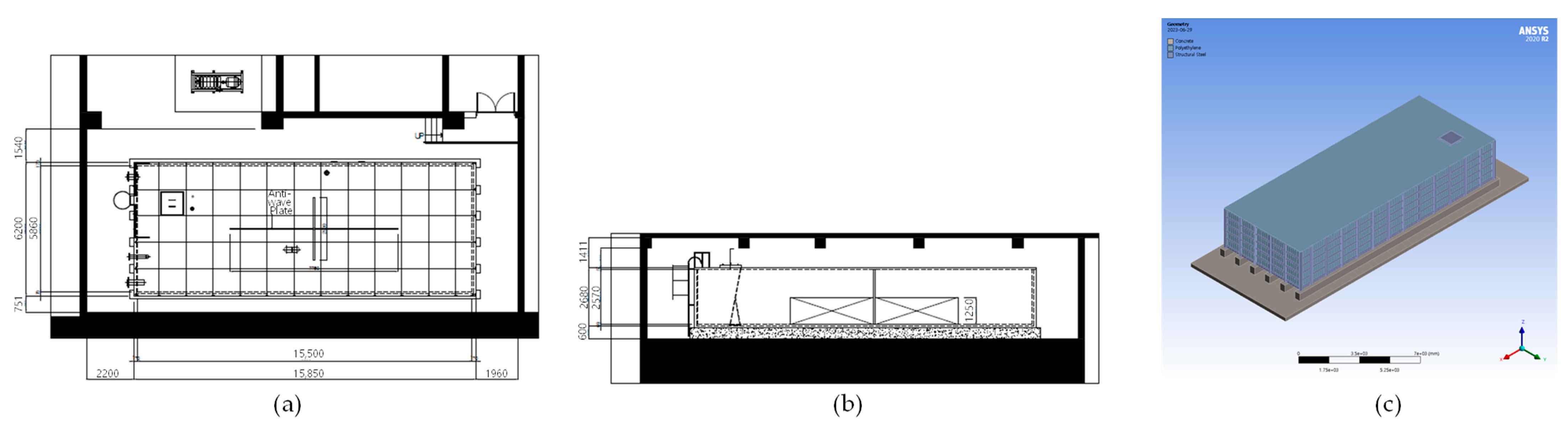
3.1. Target Structure

The target structure shown in Figure 3 was a firefighting water tank located in an underground mechanical room. Its total capacity was 218.4 ton and its dimensions were Length × Breadth × Depth = 15,500 × 5860 × 2570 mm. The design capacity was 170 ton, 77.8% of the total capacity. The anti-wave plate was installed in the form of a cross at the centre. The dimensions of the two sizes of plate, i.e., 50%H and 70%H, were Length × Breadth × Height = 7750 × 2950 × 1250 mm and 7750 × 2950 × 1750 mm, respectively. The tank sat on a concrete pad foundation and was covered with a polyethylene double frame (PDF) panel lid.

3.2. Material Model

The target structures consisted of three materials: the concrete pad, the PDF panel, and steel beam frames. Figure 4 depicts the parts of each material, which are highlighted in green. Table 2 summarises the mechanical properties of each material. Material models for both quasi-static and transient analyses were elastic conditions.

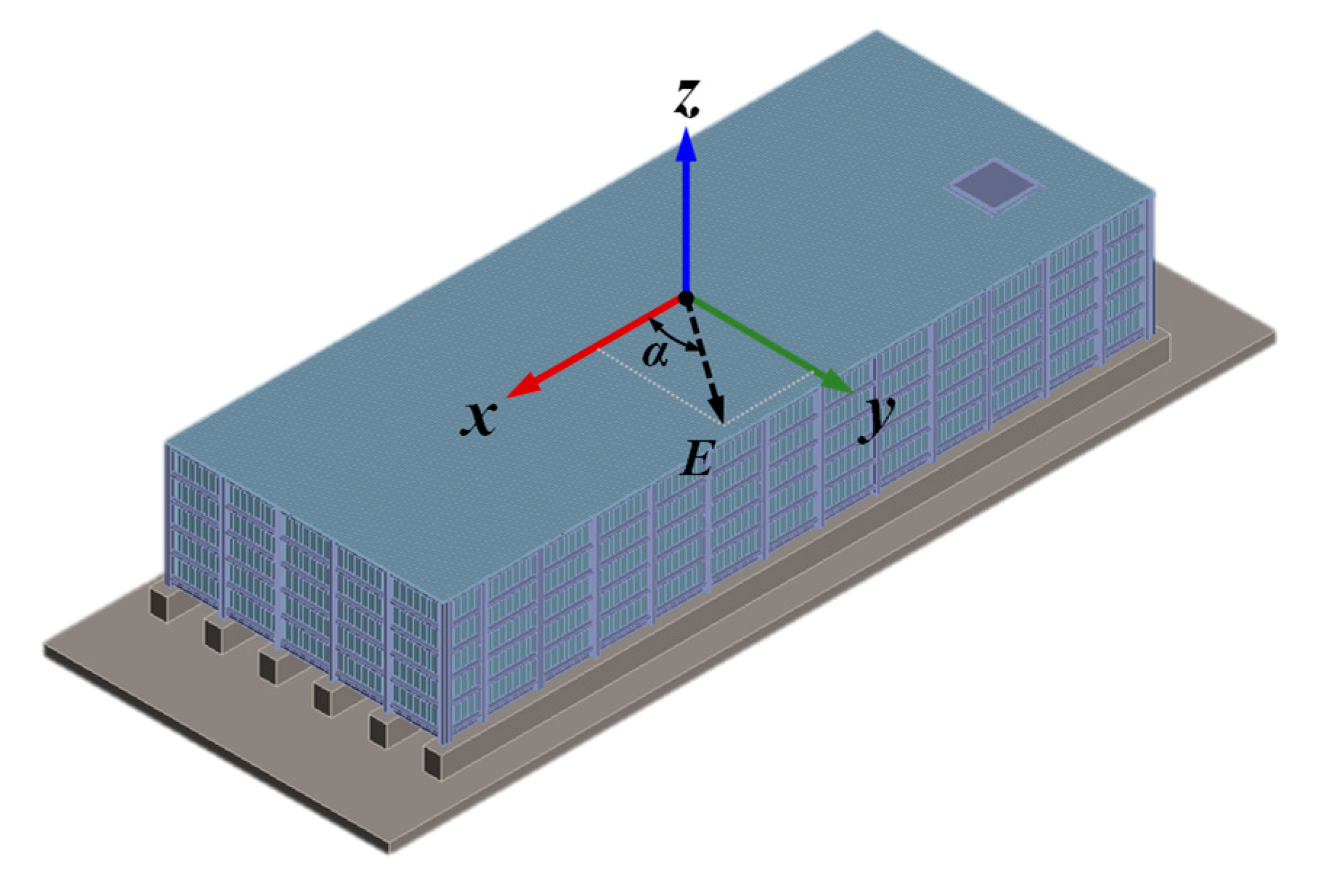
3.3. Loading and Boundary Conditions
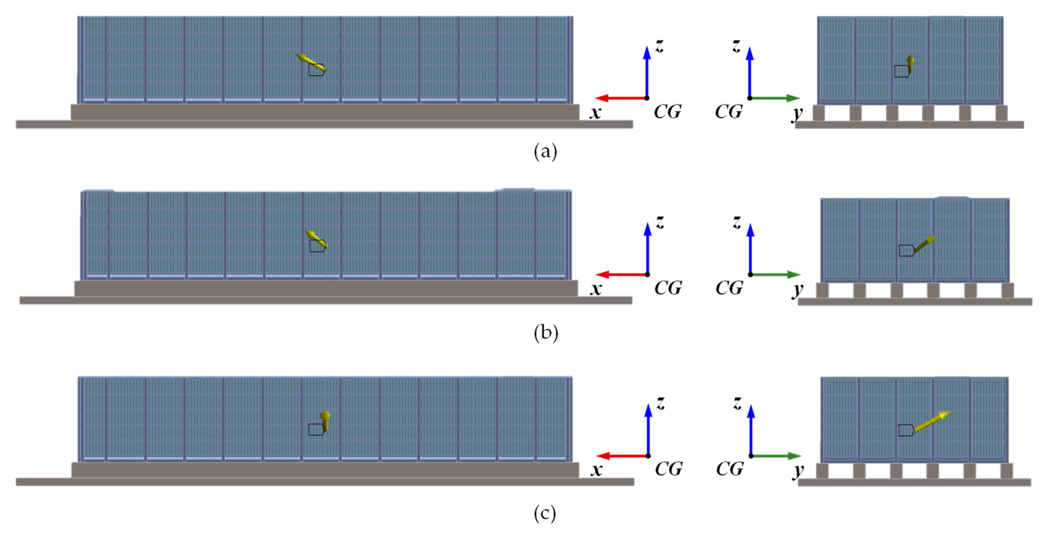
3.3.1. Loading

The loading used two conditions. The first condition was zero period acceleration, which was used for the quasi-static analysis. The second condition consisted of the time histories of the earthquake, which were calculated from the design standard and used for the transient and one-way FSI analyses.
In the quasi-static analysis, the zero period acceleration was determined based on the results of the response spectrum of the seismic load. The accelerations on the x-, y-, and z-axes at the zero period were 0.205× g, 0.236× g, and 0.101× g, respectively Therefore, the accelerations of the quasi-static analysis in the horizontal and vertical directions were 1.5 and 0.8 times the maximum values, respectively.
The seismic loads in the transient and one-way FSI analyses are shown in Figure 5. Their response spectra were compared with the required level suggested by the Korea Building and Structure Code (2022). This revealed that the seismic loads were in accordance with the design criteria. The maximum acceleration occurred at 16.9 s.

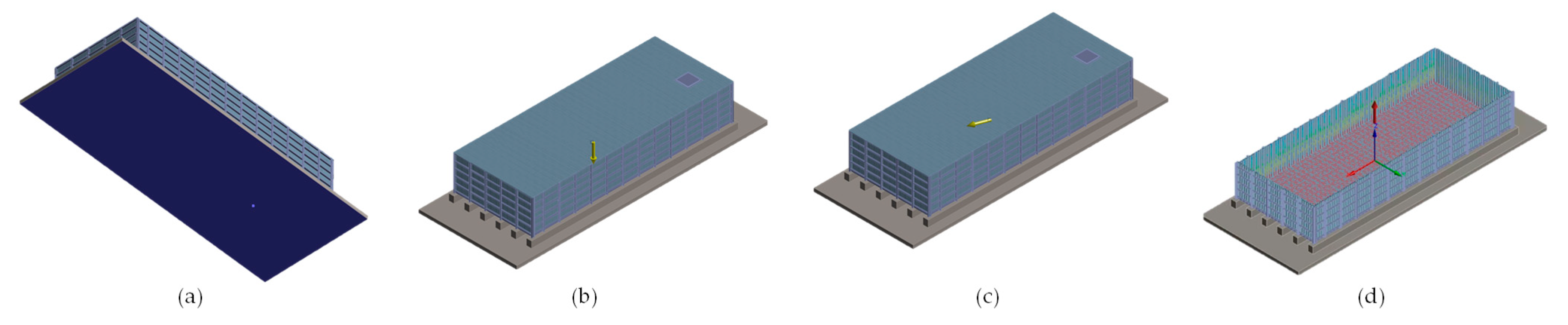
3.3.2. Boundary Conditions
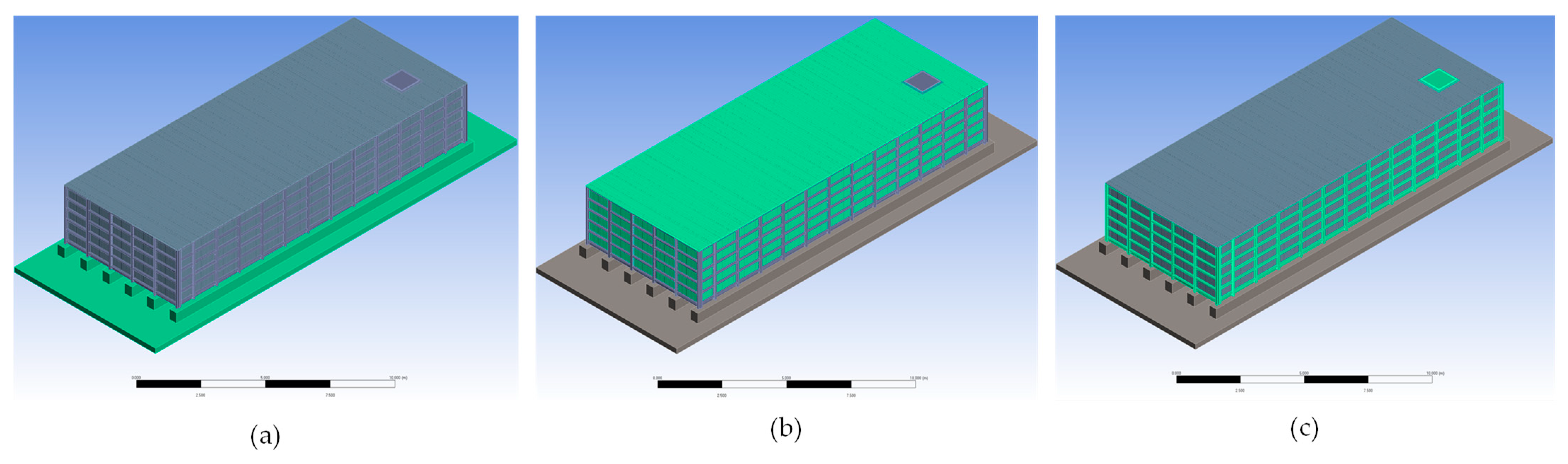
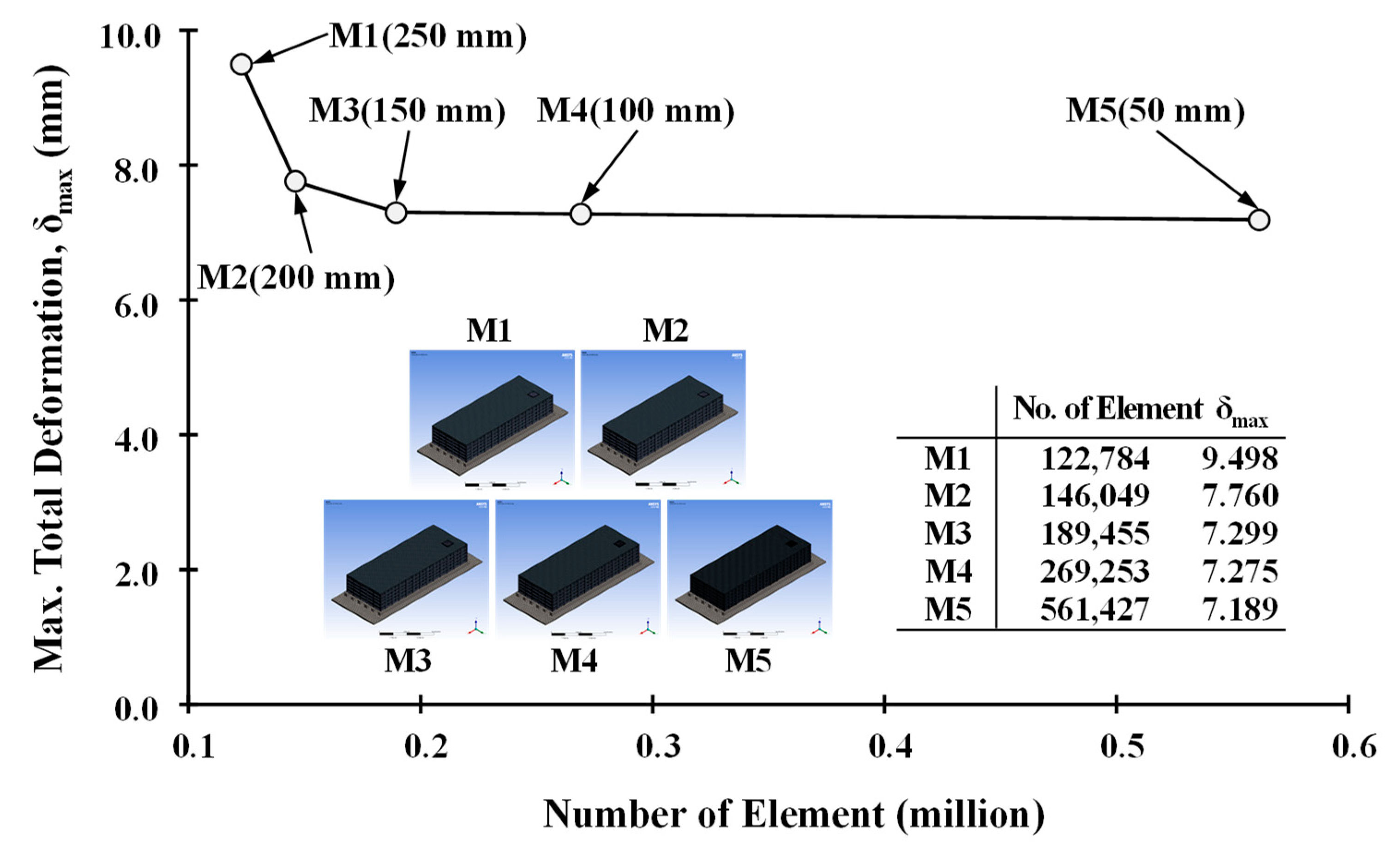
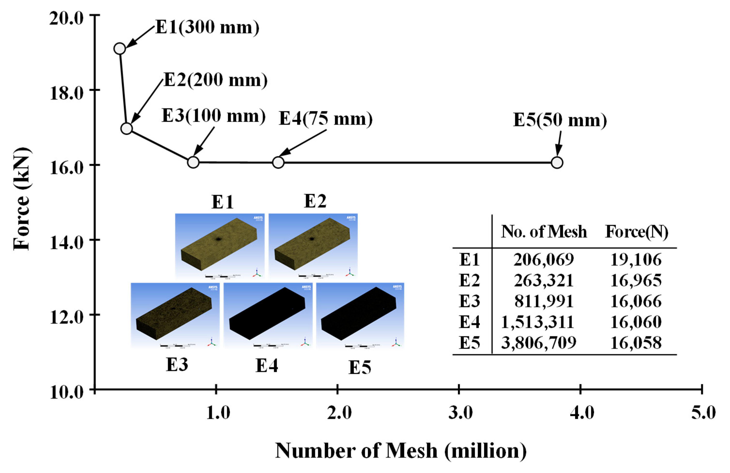
The boundary conditions between components were defined as shown in Figure 6. A fixed condition was applied to the bottom of the concrete pad. The connection between the concrete pad and the steel beam frame was assumed to be fixed. Between the PDF panel and the steel frame, contact conditions that allowed sliding were applied. It was assumed that the main members of the steel beam frame were completely fixed.
To quantify the dead load, D, gravitational acceleration was set for the whole structure. Seismic acceleration, E, was applied to the centre of gravity in the water tank. The hydrostatic pressure, H, inside the water tank was modelled according to the coordinates on the z-axis from the bottom of the tank. Furthermore, a no-separation contact condition was applied between the steel beam frame and the PDF panel. This condition linked the target and contact surface, thereby allowing the contacting nodes to move in a tangential direction. Figure 6 shows the definitions of the boundary conditions used in the FEM analysis.
In the quasi-static structural analysis, zero period acceleration was applied in three directions, with the maximum derived zero period acceleration being 0.236× g on the y-axis. According to the design criteria, the factors in the horizontal and vertical directions were defined as 1.5 and 0.8. Figure 7 gives the schematic definitions of the seismic loads, based on the magnitude, E, and the angle, α, from the x-axis. Table 3 summarises the detail of seismic load cases shown in Figure 8.
In the transient structural and one-way FSI analyses, the seismic acceleration time histories shown in Figure 5 were directly applied at the centre of gravity for 30 s. The total simulation time was 45 s, as this allowed the post behaviour of the whole structure to be captured. The size of time step in FEM was 0.05 s.
In the quasi-static and transient structural analyses, the fluid in the tank was assumed to be a solid body. In contrast, in the one-way FSI analysis, the calculated pressure—which was caused by the sloshing in the tank—was applied to the tank wall.

3.4. Mesh Model

In a numerical analysis, the size of a generated mesh affects the accuracy of the solution. Therefore, prior to a series of numerical analyses, a mesh dependency test should be performed to reduce mesh-induced analysis errors. This section describes the mesh dependency tests carried out via the FEM and FVM, respectively.

3.4.1. Finite Element Method

The target structure consisted of three components: the concrete pad, the PDF panel, and the steel beam frame. SOLID186 is a high-order 3D 20-node element with three degrees of freedom per node, and was defined and generated for modelling the concrete pad and steel beam frame. SHELL181 is a four-node element with six degrees of freedom at each node, and was defined and generated for modelling the PDF panel.
The mesh dependency of the FEM model was determined via linear quasi-static analysis. Five element sizes (50, 100, 150, 200, 250 mm) were tested for the steel beam frame, which was the primary structural component of the water tank. Figure 9 depicts the results of the mesh dependency test of the maximum total deformation in terms of the mesh size. As can be seen, the proper element size was determined by M3, and was 150 mm.

3.4.2. Finite Volume Method

In the liquid sloshing simulation, a k-ε turbulence model for fluid and the VOF method for the free surface were applied to the water tank model and simulated using ANSYS CFX (ver. 20R2) at full scale. Incompressible flow was assumed for the sloshing simulation. The time step was 0.01 s, which was sufficient to capture the pressure on the wall and to simulate the behaviour of the free surface in the water tank. In the mesh convergence study, the total simulation time was only 5.0 s.
Five mesh sizes (50, 75, 100, 200, 300 mm) were tested to examine the effect of the mesh size on the free surface profile in the longitudinal direction (i.e., on the x-axis) under seismic loads. Figure 10 shows comparisons of the forces acting on the water tank wall in terms of the free surface profile with various mesh sizes. As can be seen, the force converged as the mesh size decreased. Therefore, the proper mesh size for the sloshing simulation was 100 mm. The total number of mesh elements was approximately 3.8 million.

4. Numerical Results

This section summarises the numerical results obtained using the conditions presented in Table 1. First, the structural response in the quasi-static condition under zero period acceleration is presented and compared with the results in the transient condition under seismic load time histories. Subsequently, the three cases of one-way FSI analysis results are presented. Finally, the effect of the anti-wave plate on the structural response is discussed.

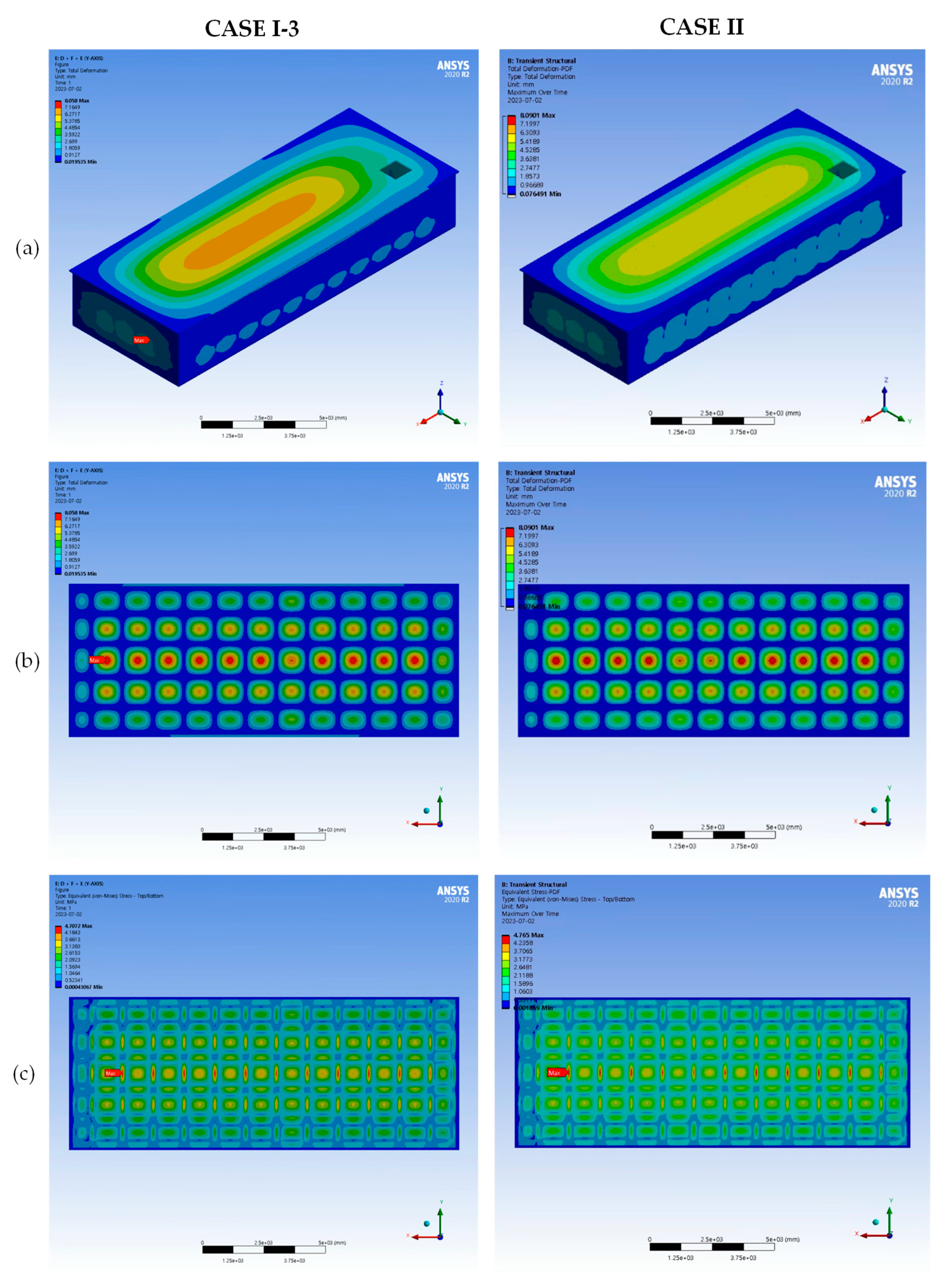
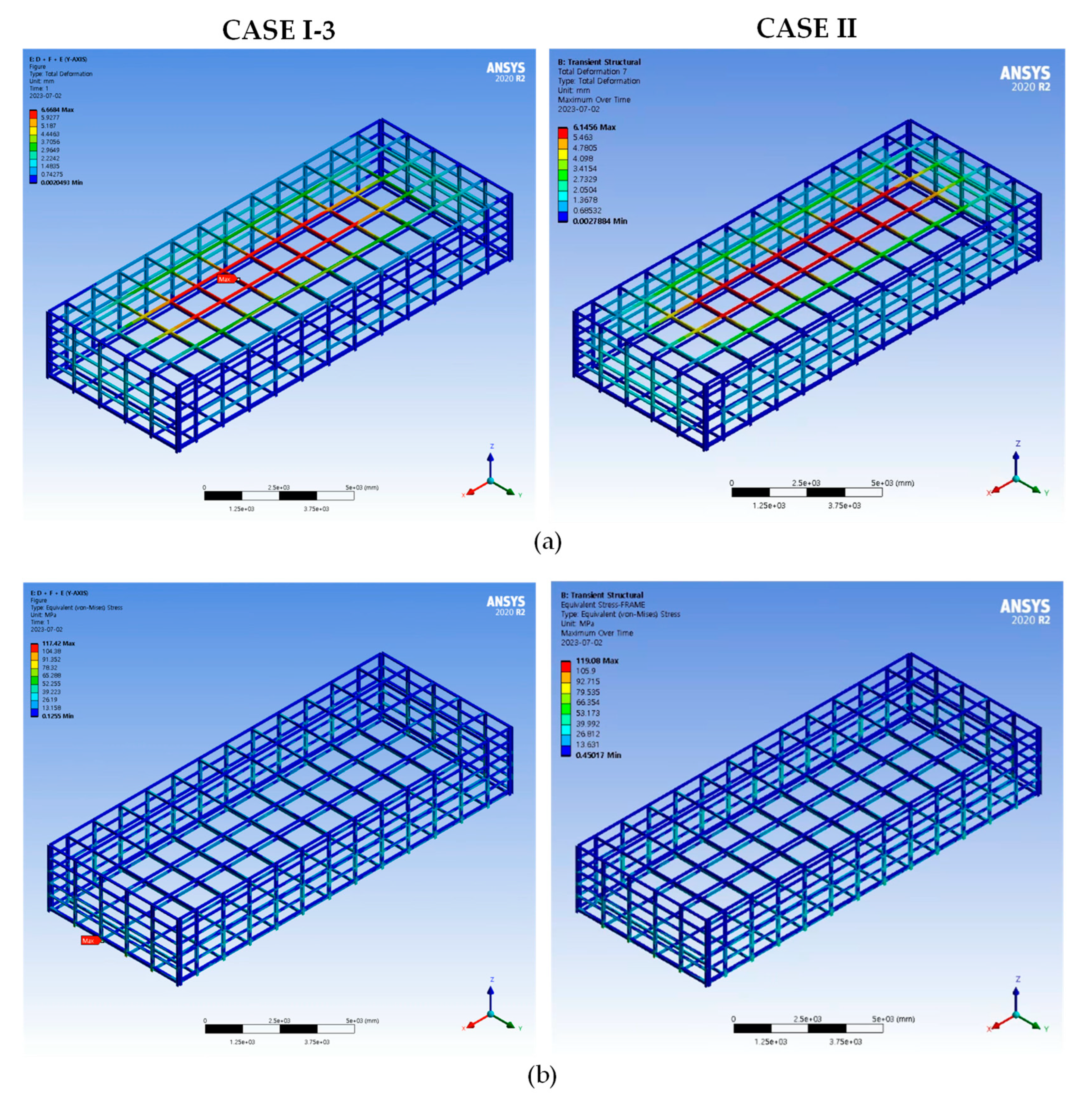
4.1. Quasi-Static Structural Analysis

Table 4 shows the maximum total deformation, von Mises, and shear stress results generated by the FEMs of the three structural components. CASE I-3 showed the largest response, although the structural response under the three load conditions was very similar. The largest deformation occurred in the PDF, and the maximum von Mises stress occurred in the steel beam frame near the bottom of the water tank. The structural response of the concrete pad was considerably smaller than those of the other structures, and thus it was not considered in the following calculations. As an example, Figure 11 illustrates the total deformation and von Mises stress of the concrete pad, the PDF panel, and the steel beam frame in the quasi-static structural analysis of CASE I-3.

4.2. Transient Structural Analysis

Figure 12 compares the total deformation and von Mises stress of the components of the water tank in the quasi-static and transient structural analyses. CASE I-3 represents the final step of the quasi-static analysis, whereas CASE II shows the structural response at the time of maximum total deformation and von Mises stress.
Figure 13 describes the structural responses for the steel beam frame in terms of the analysis method. From Figure 12, a pattern of total deformation appeared in the side wall of the PDF panel due to the difference of the loads, i.e., the zero period acceleration and the time histories of acceleration. However, there was no significant difference between the applied numerical methods’ level of structural responses. Table 5 shows the maximum total deformation and von Mises stress results of the FEM analyses of the three structural components in the transient structural analysis.

4.3. One-Way FSI Analysis

Next, a one-way FSI analysis method was developed using the ANSYS Workbench (ver. 2020R2). Using the System Coupling module, the transient structural and CFX analyses were coupled. This section reviews the effect of the anti-wave plate on the free surface motion in the water tank and its structural consequences. The results of the sloshing and the transient structural analysis are also discussed.
In this section, FVM modelling methods were developed to supplement the FEM modelling methods used in the transient analysis. Interaction interfaces were set and used to transfer the calculated pressure on the tank wall from the flow analysis. The convergence of the sloshing analysis in FVM was defined as the root mean square of the residual coefficients falling to less than 1 × 10⁻⁴, and the size of time step was 0.01 s.
The developed analysis process of the one-way FSI analysis is as follows. Initially, sloshing analysis in FVM was performed until the solution converged under seismic loads. Second, pressure results for the tank wall were transferred from the FVM to the FEM model to be mapped. Finally, the transient structural analysis was performed at the mapped pressure on the tank wall to obtain a structural response.

4.3.1. Sloshing Analysis

There are two types of anti-wave plates, 50%H and 70%H, considered in Section 3.1. The detailed settings of the flow analysis were the same as those mentioned in Section 3.4.2.
Figure 14 illustrates the change in the free surface of the tank under seismic loads with and without the anti-wave plate. A change in the free surface in the presence of the anti-wave plate began at 15 s and became significant by 35 s, when the seismic loading ended.
Figure 15 compares the forces acting on the tank wall under seismic loads with and without the anti-wave plate. It was confirmed that the force acting on the tank wall started to decrease at approximately 20 s. The effectiveness of the anti-wave plate was evident after 30 s, when the seismic loading ended. However, the difference between CASE III-2 and CASE III-3 was not significant. This indicates that the anti-wave plate mitigated both the free surface motion and the forces generated by the sloshing, but it is not recommended to design a greater height of the plate.

4.3.2. Transient Structural Analysis

This section examines the one-way FSI analysis, which applied the pressure calculated by the sloshing analysis to the FEM model under seismic loads.
Figure 16 and Figure 17 compare the total deformation and von Mises stress, respectively, for the components of the water tank in the one-way FSI analysis. CASE I-3 represents the final step of the quasi-static analysis, whereas CASE II and CASE III show the structural response at the times of maximum total deformation and von Mises stress. Table 6 summarises the maximum values of the total deformation and von Mises stress over the entire analysis.
Figure 16 describes the contour of structural responses for the PDF panel in the one-way FSI analysis. CASE III took fluid interactions into account and showed a significantly greater maximum level of both total deformation and von Mises stress than CASE II, as shown in Figure 13. This indicates that fluid interactions are essential for determining high-accuracy structural responses under seismic loads.
Comparing CASEs III-1, -2, and -3 shows that the anti-wave plate clearly decreased the structural responses in the PDF panel. In particular, the total deformation at the bottom of the PDF panel was decreased as the size of the anti-wave plate increased. However, the maximum von Mises stress occurred near the connection between the bottom of the PDF panel and the anti-wave plate, as shown in Figure 17b. Therefore, while the anti-wave plate mitigated structural responses, a systematic design process is needed to prevent a significant increase in stress at the connection.
Figure 17 shows the contour of structural responses for the steel beam frame in the one-way FSI analysis. The structural responses decreased from CASE III-1 to CASEs III-2 to CASE III-3, due to the anti-wave plate increasingly mitigating the free surface motion.

5. Conclusions

This study developed three numerical methods—a quasi-static structural method, a transient structural method, and a one-way FSI analysis method, based on convergence studies from FEM and FVM—for modelling a firefighting water tank. These methods were used to assess the structural integrity of the tank under seismic loads. The following conclusions can be drawn.
(1)
There was no significant difference in the level of structural responses between the quasi-static (CASE I-3) and transient (CASE II) structural analysis. However, the one-way FSI (CASE III-1) analysis, which took fluid interactions into account, exhibited a significantly larger maximum total deformation and von Mises stress than the CASE I-3 and CASE II analyses. It was found that the amount of the total deformation and von Mises stress for the PDF panel at CASE III-1 increased by 85.8% and 87.2% against CASE I-3 and 85.1% and 84.3% against CASE II. This indicates that fluid interactions must be considered to obtain high-accuracy estimates of structural responses of water tanks under seismic loads.
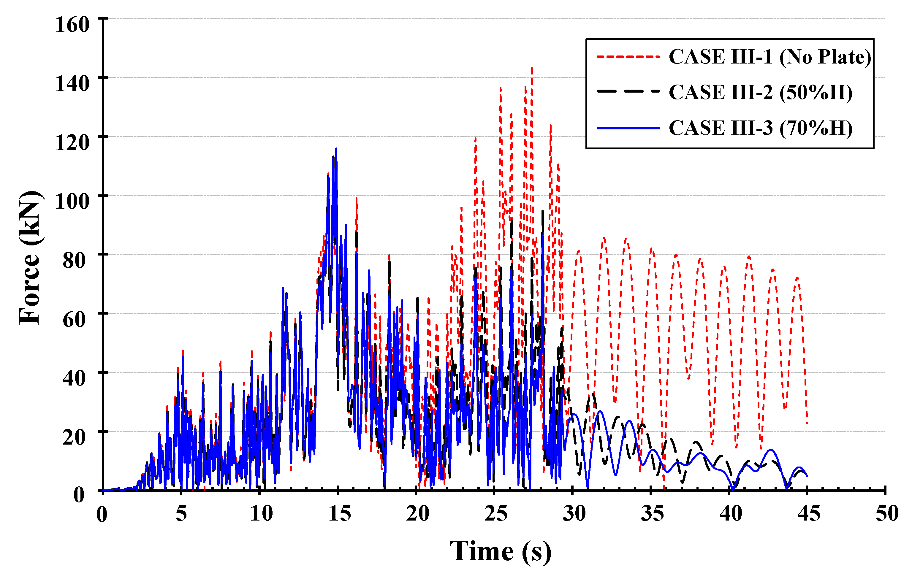
(2)
The anti-wave plate affected both the free surface behaviour and the force generated by the sloshing in the tank wall, as demonstrated by the CASE III-1 and CASE III-2 analyses. However, the effect of the anti-wave plate height was not significantly appeared between CASE III-2 and CASE III-3. This demonstrates that the anti-wave plate is capable of mitigating both the free surface motions and the forces, but a higher anti-wave plate does not guarantee a more significant effect. Therefore, the optimal height of an anti-wave plate must be systematically assessed.
(3)
The anti-wave plate clearly decreased the structural responses in the PDF panel, as was shown by comparing the CASE III-1, III-2, and III-3 analyses. However, the maximum von Mises stress occurred near the connection between the bottom of the PDF panel and the anti-wave plate. Therefore, while the anti-wave plate effectively mitigated structural responses, a systematic design process should be employed when using an anti-wave plate, such that a significant increase in stress at the connection is prevented.
We hope that the numerical modelling methods developed in this study will aid engineers and designers in the construction industries. We note that to improve the accuracy of the developed numerical modelling methods, a two-way FSI should be considered.

Author Contributions

Conceptualization, D.-M.L. and S.-E.L.; methodology, D.-M.L. and S.-E.L.; ANSYS Workbench (ver. 2020R2), S.-E.L.; formal analysis, S.-E.L.; investigation, D.-M.L. and S.-E.L.; resources, S.-E.L.; data curation, S.-E.L.; writing—original draft preparation, S.-E.L.; writing—review and editing, S.-E.L.; visualization, S.-E.L.; supervision, S.-E.L.; project administration, D.-M.L. and S.-E.L.; funding acquisition, S.-E.L. All authors have read and agreed to the published version of the manuscript.

Funding

This research was also supported by the Basic Science Research Program through the National Research Foundation of Korea (NRF), funded by the Ministry of Education (NRF-2015R1A6A3A01060166, NRF-2017R1A6A3A03003742).

Conflicts of Interest

The authors declare no conflict of interest.

References

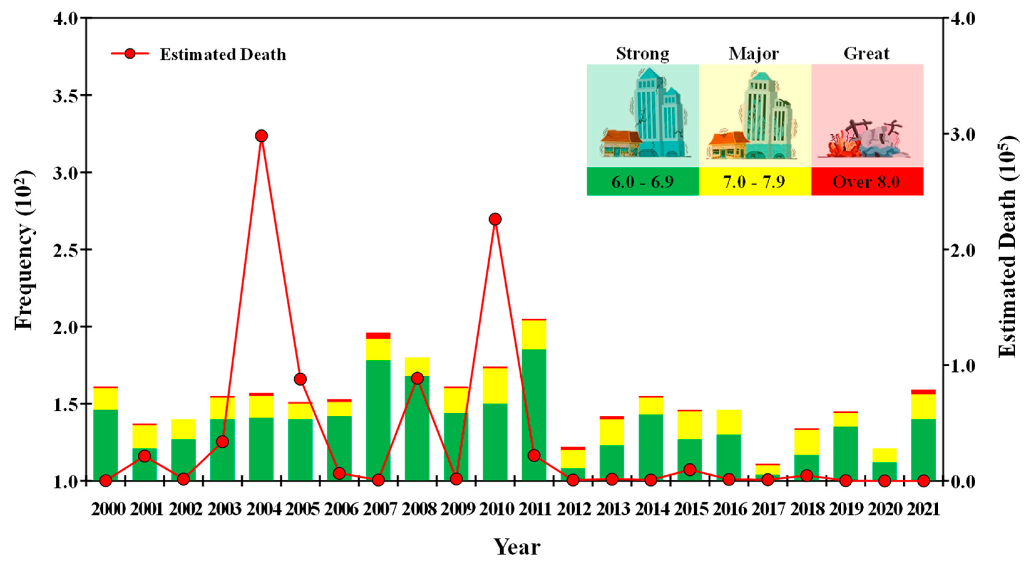
  1. World Wide Earthquake 2000–2021. Available online: www.usgs.gov (accessed on 26 April 2023).
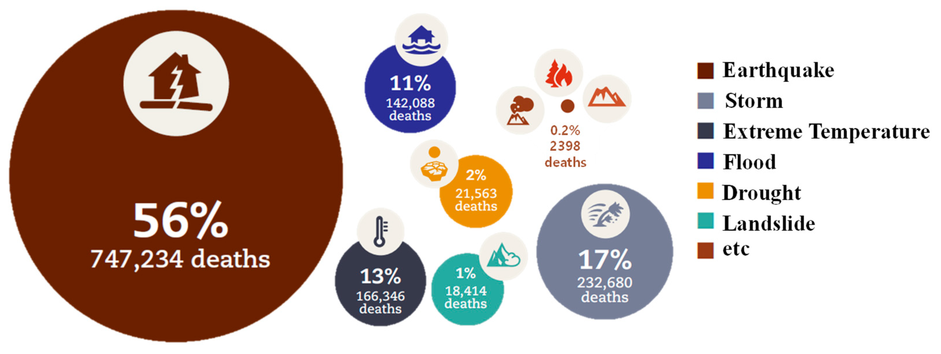
  2. Mizutori, M.; Guha-Sapir, D. Economic Losses, Poverty & Disasters 1998–2017; Centre for Research on the Epidemiology of Disasters CRED: Brussels, Belgium; United Nations Office for Disaster Risk Reduction: Geneva, Switzerland, 2018. [Google Scholar]
  3. Akyildiz, H.; Unal, E. Experimental investigation of pressure distribution on a rectangular tank due to the liquid sloshing. Ocean Eng. 2005, 32, 1503–1516. [Google Scholar] [CrossRef]
  4. Panigrahy, P.K.; Saha, U.K.; Maity, D. Experimental studies on sloshing behavior due to horizontal movement of liquids in baffled tanks. Ocean Eng. 2009, 36, 213–222. [Google Scholar] [CrossRef]
  5. Jin, H.; Liu, Y.; Li, H.J. Experimental study on sloshing in a tank with an inner horizontal perforated plate. Ocean Eng. 2014, 82, 75–84. [Google Scholar] [CrossRef]
  6. Xue, M.A.; Zheng, J.; Lin, P.; Yuan, X. Experimental study on vertical baffles of different configurations in suppressing sloshing pressure. Ocean Eng. 2017, 136, 178–189. [Google Scholar] [CrossRef]
  7. Kim, S.P.; Chung, S.M.; Shin, W.J.; Cho, D.S.; Park, J.C. Experimental study on sloshing reduction effects of baffles linked to a spring system. Ocean Eng. 2018, 170, 136–147. [Google Scholar] [CrossRef]
  8. Yu, L.; Xue, M.A.; Jiang, Z. Experimental investigation of parametric sloshing in a tank with vertical baffles. Ocean Eng. 2020, 213, 107783. [Google Scholar] [CrossRef]
  9. Isaacson, M.; Premasiri, S. Hydrodynamic damping due to baffles in a rectangular tank. Can. J. Civ. Eng. 2001, 28, 608–616. [Google Scholar] [CrossRef]
  10. Gedikli, A.; Erguven, M.E. Evaluation of sloshing problem by variational boundary element method. Eng. Anal. Bound. Elem. 2003, 27, 935–943. [Google Scholar] [CrossRef]
  11. Wang, J.D.; Lo, S.H.; Zhou, D. Sloshing of liquid in rigid cylindrical container with multiple rigid annular baffles: Lateral excitations. J. Fluids Struct. 2013, 42, 421–436. [Google Scholar] [CrossRef]
  12. Sun, Y.; Zhou, D.; Wang, J. An equivalent mechanical model for fluid sloshing in a rigid cylindrical tank equipped with a rigid annular baffle. Appl. Math. Model. 2019, 72, 569–587. [Google Scholar] [CrossRef]
  13. Liu, D.; Lin, P. Three-dimensional liquid sloshing in a tank with baffles. Ocean Eng. 2009, 36, 202–212. [Google Scholar] [CrossRef]
  14. Jung, J.H.; Yoon, H.S.; Lee, C.Y.; Shin, S.C. Effect of the vertical baffle height on the liquid sloshing in a three-dimensional rectangular tank. Ocean Eng. 2012, 44, 79–89. [Google Scholar] [CrossRef]
  15. Yu, Y.M.; Ma, N.; Fan, S.M.; Gu, X.C. Experimental and numerical studies on sloshing in a membrane-type LNG tank with two floating plates. Ocean Eng. 2017, 129, 217–227. [Google Scholar] [CrossRef]
  16. Sanapala, V.S.; Velusamy, R.M.K.; Patnaik, B.S.V. Numerical simulation of parametric liquid sloshing in a horizontally baffled rectangular container. J. Fluids Struct. 2018, 76, 229–250. [Google Scholar] [CrossRef]
  17. Wang, Q.Y.; Lin, G.M.; Jiang, L.; Zheng, G.F.; Chen, J.J. Numerical and experimental study of anti-slosh performance of combined baffles in partially filled tank vehicles. Int. J. Press. Vessel. Pip. 2022, 196, 104555. [Google Scholar] [CrossRef]
  18. Biswal, K.C.; Bhattacharyya, S.K.; Sinha, P.K. Dynamic response analysis of a liquid-filled cylindrical tank with annular baffle. J. Sound Vib. 2004, 274, 13–37. [Google Scholar] [CrossRef]
  19. Cho, J.R.; Lee, H.W. Numerical study on liquid sloshing in baffled tank by nonlinear finite element method. Comput. Methods Appl. Mech. Eng. 2004, 193, 2581–2598. [Google Scholar] [CrossRef]
  20. Cho, J.R.; Lee, H.W.; Ha, S.Y. Finite element analysis of resonant sloshing response in a 2D baffled tank. J. Sound Vib. 2005, 228, 829–845. [Google Scholar] [CrossRef]
  21. Eswaran, M.; Saha, U.K.; Maity, D. Effect of baffles on a partially filled cubic tank: Numerical simulation and experimental validation. Comput. Struct. 2009, 87, 198–205. [Google Scholar] [CrossRef]
  22. Iranmanesh, A.; Nikbakhti, R. Numerical study on suppressing liquid sloshing of a rectangular tank using moving baffles linked to a spring system. Ocean Eng. 2021, 229, 109002. [Google Scholar] [CrossRef]
Figure 1. Statistics of worldwide earthquake 2000–2021 [1].
Applsci 13 11689 g001
Figure 2. Number of deaths per disaster type 1998–2017 [2].
Applsci 13 11689 g002
Figure 3. Drawing and geometry of the firefighting water tank. (a) Drawing in top view; (b) Drawing in side view; (c) Generated geometry model in ANSYS Workbench.
Applsci 13 11689 g003
Figure 4. Material definition of the target structure (highlighted in green colour). (a) Concrete pad; (b) PDF panel; (c) Steel beam frame.
Applsci 13 11689 g004
Figure 5. Calculated acceleration and its response spectrum of the seismic load. (a) Time histories of acceleration in x-axis; (b) Response spectrum of acceleration in x-axis; (c) Time histories of acceleration in y-axis; (d) Response spectrum of acceleration in y-axis; (e) Time histories of acceleration in z-axis; (f) Response spectrum of acceleration in z-axis.
Applsci 13 11689 g005
Figure 6. Definition of boundary conditions in the quasi-static the transient structural analysis. (a) Fixed boundary condition applied at the bottom of the concrete pad; (b) Dead load (yellow arrow), D, applied to the firefighting water tank; (c) Applied seismic load (yellow arrow), E, at the centre of the tank; (d) An example of the hydrostatic pressure (red arrow) applied to the inside of the tank.
Applsci 13 11689 g006
Figure 7. Schematic definition of the seismic loading in the quasi-static structural analysis.
Applsci 13 11689 g007
Figure 8. Applied zero period acceleration (yellow arrow) in quasi-static structural analysis. (a) CASE I-1; (b) CASE I-2; (c) CASE I-3.
Applsci 13 11689 g008
Figure 9. Results of the mesh dependency test on the steel frame for total deformation.
Applsci 13 11689 g009
Figure 10. Results of mesh convergence test for the force acting on the water tank wall.
Applsci 13 11689 g010
Figure 11. Structural responses of the firefighting water tank in the quasi-static structural analysis under CASE I-3. (a) Total deformation of the concrete pad; (b) Total deformation of the PDF panel; (c) Total deformation of the steel beam frame; (d) von Mises stress of the concrete pad; (e) von Mises stress of the PDF panel at the bottom; (f) von Mises stress of the steel beam frame.
Applsci 13 11689 g011
Figure 12. Structural response comparison of the PDF panel between the quasi-static (CASE I-3) and transient (CASE II) structural analysis. (a) Total deformation; (b) Total deformation at the bottom; (c) von Mises stress at the bottom.
Applsci 13 11689 g012
Figure 13. Structural response comparison of the steel beam frame between the quasi-static (CASE I-3) and transient (CASE II) structural analysis. (a) Total deformation; (b) von Mises stress.
Applsci 13 11689 g013
Figure 14. Comparison of free surface motion amongst CASE III-1, -2, and -3. (a) CASE III-1, no plate; (b) CASE III-2, 50%H; (c) CASE III-3, 70%H.
Applsci 13 11689 g014
Figure 15. Comparison of forces acting on the tank wall amongst CASE III-1, -2, and -3.
Applsci 13 11689 g015
Figure 16. Structural response comparison of the PDF panel amongst CASE III-1, -2 and -3. (a) Total deformation; (b) Total deformation at the bottom; (c) von Mises stress.
Applsci 13 11689 g016
Figure 17. Structural response comparison of the steel beam frame amongst CASE III-1, -2 and -3. (a) Total deformation; (b) von Mises stress.
Applsci 13 11689 g017
Table 1. Cases of numerical simulations. (■ means the applied conditions in the present study).
CaseStructureFluidAnti-Wave Plate
StaticTransientNo Plate50%H70%H
CASE I-1,2,3
CASE II
CASE III-1
CASE III-2
CASE III-3
Table 2. Mechanical properties.
MaterialDensity
(kg/m3)
Modulus of Elasticity
(MPa)
Poisson’s
Ratio
(−)
Yield Strength(MPa)Ultimate Strength
(MPa)
Concrete230030,0000.18-24
PDF Panel98011000.422533
Carbon Steel7850200,0000.30250460
Table 3. Load case in the quasi-static structural analysis.
Load CaseFactor
(-)
α (deg) Load
(g)
CASE I-1x-axis1.50.00.3540
y-axis1.50.0000
z-axis0.80.1888
CASE I-2x-axis1.545.00.2440
y-axis1.50.2440
z-axis0.80.1888
CASE I-3x-axis1.590.00.0000
y-axis1.50.3540
z-axis0.80.1888
Table 4. Comparison of structural response in quasi-static analysis.
CaseItemConcrete
Foundation
PDF PanelSteel Beam Frame
CASE I-1
(No Plate)
Total Deformation (mm)0.0288.0566.595
von Mises Stress (MPa)8.8834.761110.970
Shear Stress (MPa)XY-Plane0.5940.78525.228
YZ-Plane1.6951.46640.429
ZX-Plane1.4690.31135.760
CASE I-2
(No Plate)
Total Deformation (mm)0.0288.0576.631
von Mises Stress (MPa)8.7314.745112.100
Shear Stress (MPa)XY-Plane0.5860.77423.922
YZ-Plane1.6941.46637.589
ZX-Plane1.4690.31236.599
CASE I-3
(No Plate)
Total Deformation (mm)0.0278.0586.668
von Mises Stress (MPa)8.3974.707117.420
Shear Stress (MPa)XY-Plane0.5670.77923.227
YZ-Plane1.6931.46635.695
ZX-Plane1.4690.31338.363
Table 5. Comparison of structural response in the transient analysis.
CaseItemPDF PanelSteel Beam Frame
CASE II
(Transient,
No Plate)
Total Deformation (mm)8.0906.146
von Mises Stress (MPa)4.779119.080
Shear Stress (MPa)XY-Plane-24.089
YZ-Plane-40.425
ZX-Plane-38.739
Table 6. Comparison of structural response in quasi-static, transient, and one-way FSI analysis.
CaseItemPDF PanelSteel Beam Frame
CASE III-1
(1-way FSI,
No Plate)
Total Deformation (mm)14.9717.268
von Mises Stress (MPa)8.810228.780
Shear Stress (MPa)XY-Plane-50.049
YZ-Plane-83.310
ZX-Plane-76.143
CASE III-2
(1-way FSI, 50%H)
Total Deformation (mm)12.4815.622
von Mises Stress (MPa)7.556183.040
Shear Stress (MPa)XY-Plane-36.514
YZ-Plane-62.819
ZX-Plane-61.154
CASE III-3
(1-way FSI, 70%H)
Total Deformation (mm)12.4795.367
von Mises Stress (MPa)9.462179.140
Shear Stress (MPa)XY-Plane-38.640
YZ-Plane-67.177
ZX-Plane-59.614
Disclaimer/Publisher’s Note: The statements, opinions and data contained in all publications are solely those of the individual author(s) and contributor(s) and not of MDPI and/or the editor(s). MDPI and/or the editor(s) disclaim responsibility for any injury to people or property resulting from any ideas, methods, instructions or products referred to in the content.

