Abstract
High switching frequency and fast switching speed of wide bandgap power semiconductor device-based power converters may increase radiated emissions more than conventional silicon-power device-based power converters. Based on the background, this article experimentally investigates radiated emission sources in buck converters. The experimental system constructed in this article has two common-mode noise paths, the primary common-mode and the secondary common-mode. First, this article outlines that a secondary common-mode voltage source is caused by a primary common-mode current and an imbalance of power supply side impedances, and the secondary common-mode current path acts as a monopole antenna. The common-mode currents and the radiated emissions are measured in an anechoic chamber when the common-mode inductor for each mode is connected. The measurement results show that the primary common-mode current generates the secondary common-mode noise, and the secondary common-mode noise is the dominant source of radiated emission in the experimental system.
1. Introduction
Due to their high efficiency and controllability, power electronics technologies based on power semiconductor devices continue to expand their range of applications [1,2]. State-of-the-art wide-bandgap power semiconductor devices realize high power density because their fast-switching speed can increase the switching frequency of power converters [3]. However, as a side effect of using wide-bandgap semiconductors such as silicon carbide and gallium nitride, electromagnetic emission increases significantly even above several tens of MHz [4,5,6,7]. Thus, the practical use of wide-bandgap power devices raises concern about increased radiated emissions in power converters. In general, excessive design of electromagnetic interference (EMI) filters can be avoided by applying countermeasures based on the appropriate knowledge of noise sources.
For example, the common-mode (CM) voltage of a pulse-width-modulation (PWM) inverter is known as a conducted emission source in three-phase motor drive systems [8]. The CM voltage varies with the inverter’s switching, and CM current flows to the ground through stray capacitance between the motor windings and the frame. Various techniques have been proposed to suppress CM emissions in motor drive systems [7,9,10,11,12,13,14,15]. Ref. [9] has investigated the floating filter in which the neutral point of the sine wave filter connects to the DC midpoint of the inverter to bypass the CM current. Ref. [10] has proposed the cancellation method of CM voltage using active components such as bipolar transistors. Moreover, the CM voltage-reduction methods by changing the structure of power converters have been proposed [13,14,15,16,17,18]. On the other hand, there have been fewer studies on the source of radiated emission in power converters than on conducted emission [19,20,21,22,23,24,25,26]. As shown in Figure 1, power cables of power converters are known to act as antennas for radiated emission, and previous studies have analyzed radiated emission in power converters by applying antenna theory [23,24,25,26].
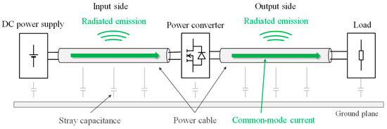
Figure 1.
Radiated emission from power cables of power converters.
Research has also addressed the use of the loss resistance of magnetic cores to suppress radiated emission from cables [20]. Moreover, an active-filtering technique for reducing radiated emission from power cables has been investigated [22]. On the other hand, power converters with ground wires and shielded cables form the secondary common-mode (SCM), in addition to the conventionally defined primary common-mode (PCM). Electromagnetic noise propagating through the SCM has been investigated for shielded cables of signal transmission systems [27,28,29]. However, the relationship between the SCM noise and radiated emission in power converters has yet to be investigated.
This article investigates the generation mechanism of radiated emission in power converters with ground wires, experimentally. The contribution of this article is to clarify that the SCM noise is a radiated emission source in power converters with ground wires and that the PCM current and an unbalance of the power supply side impedances cause the SCM noise. The rest of this article is composed as follows. First, Section 2 shows that an experimental system has two major noise propagation paths, PCM and SCM. Section 3 describes the generation mechanism of the SCM noise in the experimental system. Section 4 clarifies that the PCM current and unbalance of impedances of the power supply side causes the SCM voltage source, based on the measurement results of CM and SCM currents. Moreover, measurements of radiated emission from the experimental system are performed in a semi-anechoic chamber. The measurement results verify that the SCM noise is the source of radiated emissions in the experimental system. Note that this article is not intended to meet radiated-EMI standards in any particular power conversion system. This article aims to experimentally clarify the generation mechanism of radiated emission in power converters with the ground wire. The radiated emission generation mechanism demonstrated in this article widely applies to power converters using ground wires or shielded cables. By applying effective radiated emission suppression techniques based on this article’s result, the time and cost spent for suppressing radiated emissions are expected to be reduced.
2. Configuration of Experimental System
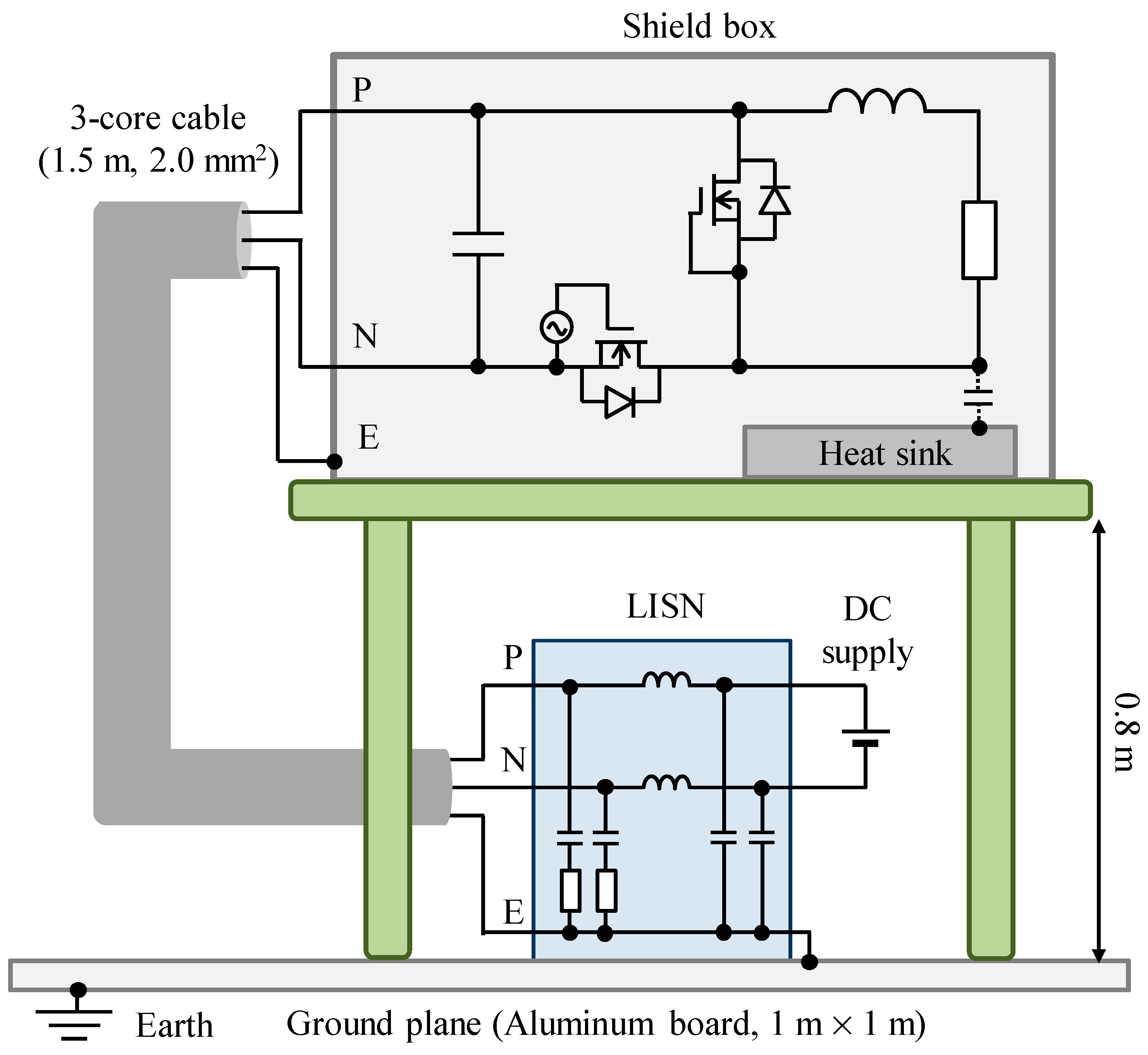
Figure 2 shows a configuration of the experimental system under evaluation in this article.

Figure 2.
Configuration of the experimental system.
A buck converter based on SiC-MOSFETs (SCT3120AL, Rohm, Kyoto, Japan) and load resister are housed inside a metal box to block radiated noise from the power converter itself. The metal box is placed on a wooden desk of which the height is about 0.8 m from a ground plane. An aluminum board (1 m × 1 m × 5 mm), which is placed on the laboratory’s floor and is grounded through LISNs, imitates the ground plane. The buck converter and a DC power supply are connected via LISNs (LI-325C, COM-POWER [30]) to stabilize an impedance of the power supply side in the frequency range under evaluation. A 1.5 m three-core cable of which cross section area of conductor is 2.0 mm2 is used for the connection between the buck converter and LISNs. Note that the metal box is connected to the ground plane via LISNs.
This article defines the following three noise propagation modes in the experimental system. First, differential-mode (DM) of which noise circulates between phases of the power converter. The noise path in which the noise propagates through the ground line E via stray capacitance, and returns through the power lines P and N, is defined as primary common-mode (PCM). Furthermore, there is another propagation path in which the noise propagates through the power lines P and N and ground line E as a whole [27,28,29]. This noise propagation path is defined as the secondary common-mode (SCM) in this article.
3. Generation Mechanism of the SCM Noise in the Experimental System
This section describes the generation mechanism of the SCM noise in the experimental system. First, the impedances of the noise sources and noise propagation paths in the experimental system shown in Figure 2 are represented as shown in Figure 3.
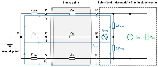
Figure 3.
Simple representation of noise sources and noise paths in the experimental system.
Here, the buck converter is represented as the behavioral model [31,32,33], where IDM is the DM current source; VPCM is the PCM voltage source; and IPCM is the PCM current. The impedance between terminals P’–N’ when the three-core cable is disconnected near the input terminal of the buck converter is denoted as ZDM. Moreover, the impedance between the input terminals of the buck converter and the metal box is ZPCM, and it is equally distributed to each phase of the buck converter. ZLISN represents the impedance of LISNs, and ZP, ZN, and ZE represent the impedances of the power lines P, N, and ground line E of the three-core cable, respectively. The impedance between the terminal E and the ground plane near LISNs is represented as ZG (ZG is depicted by a dotted line in Figure 2 because it is very small).
First, in Figure 3, assuming that each phase impedance of the three-core cable is balanced (ZP = ZN = ZE), the following Equation (1) for the PCM is derived as
Thus, the PCM current IPCM is given using
Next, assuming the PCM currents that flow through each phase are balanced, voltage potentials of the terminals P, N, and E for the ground (VP, VN, and VE) are represented as
From Equations (3)–(5), the average voltage of VP, VN, and VE, which is the CM voltage of the three-core cable as a whole VSCM, is given with
Since the impedance of the ground wire should be as small as possible for safety reasons, ZG and ZLISN are not equal, and the right side of Equation (6) is not zero. Thus, it can be considered that the SCM voltage, which is the average voltage given with Equation (6), is caused by the PCM current and the unbalance of the power supply side impedances (ZLISN ≠ ZG) in this experimental system.
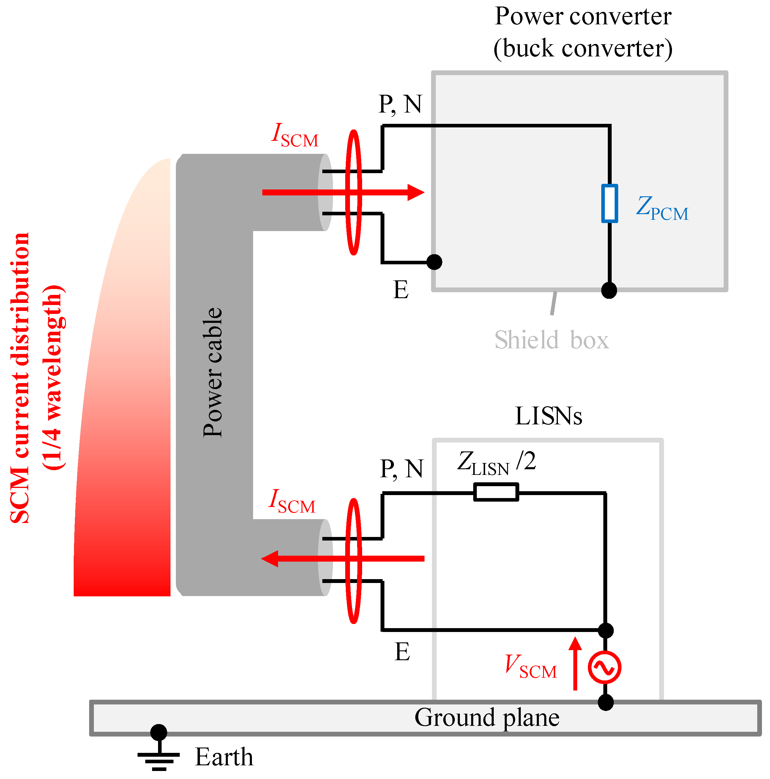
The SCM voltage VSCM causes the SCM current ISCM to flow through the entire three-core cable. The buck converter, which is housed in the metal box, is placed on the wooden table whose height is 0.8 m from the floor. Thus, the power converter side has a large SCM impedance to the ground plane. In this case, a standing wave of the SCM current with the power supply side as the antinode and the power converter side as the node is generated depending on the cable length, as shown in Figure 4.

Figure 4.
Secondary common-mode of the experimental system.
In other words, the three-core cable, which is the SCM noise propagation path, constitutes a monopole antenna and is one of the dominant sources of radiated noise in the experimental system under investigation in this article.
Equation (6) shows that suppressing the PCM current IPCM or balancing the power supply side impedances (ZLISN = ZG) effectively reduces the SCM noise. For the experimental system in this article, it is necessary to connect an artificial impedance network between the ground line terminal E and the ground plane to achieve the balance of power supply side impedances. However, in practice, the power supply side impedance is not constant over a wide bandwidth. Generally, it is difficult to accurately simulate the frequency characteristics of a power supply side impedance over wide-band frequencies. Moreover, from the viewpoint of preventing electric shock, it is undesirable to connect an impedance balancing component to the ground line of power converters. On the other hand, the PCM current can be suppressed using CM inductors (CMIs) to increase the impedance of the PCM propagation path [20,34]. The following section demonstrates the above-mentioned radiated noise generation mechanism by connecting CMIs to the experimental system and evaluating the impact of CMIs on each CM current and radiated noise based on the experimental results.
4. Noise Measurements in the Experimental System
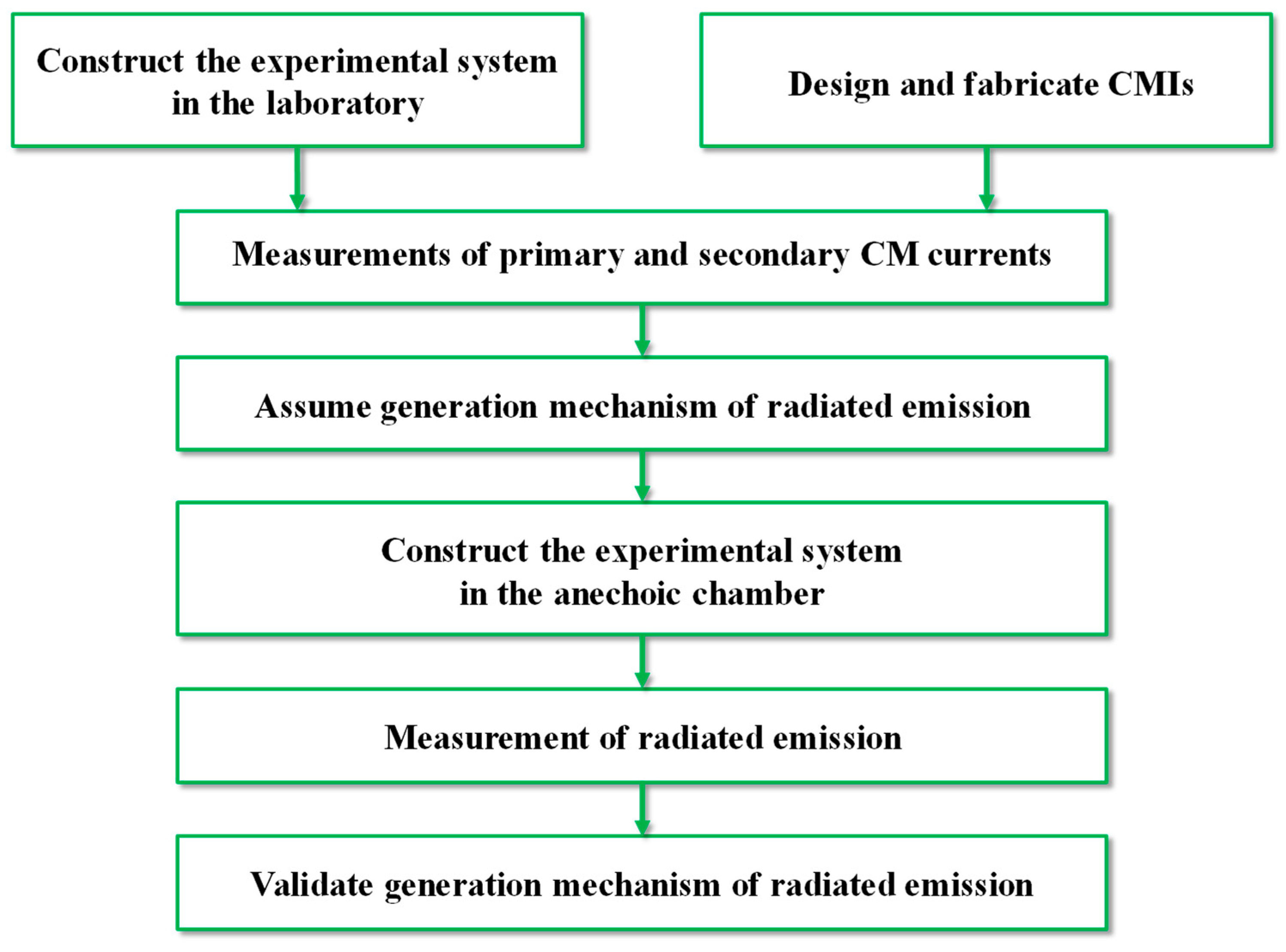
Figure 5 shows a process flow to validate the radiated emission generation mechanism in power converters with ground wires. First, an experimental system for measurement of CM currents is constructed in the laboratory. Moreover, CMIs for each noise propagation mode are designed and fabricated. Next, measurements of CM currents are performed, and impacts of CMIs on CM currents are evaluated. The generation mechanism of radiated emission from the power cable is assumed based on the measured results of CM currents. Finally, the experimental system for measurements of radiated emission is constructed in an anechoic chamber. Measurements of radiated emission are performed, and the generation mechanism of radiated emission is validated.
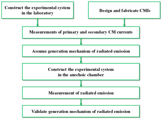
Figure 5.
Process flow to validate the generation mechanism of radiated emission.
4.1. Common-Mode Currents
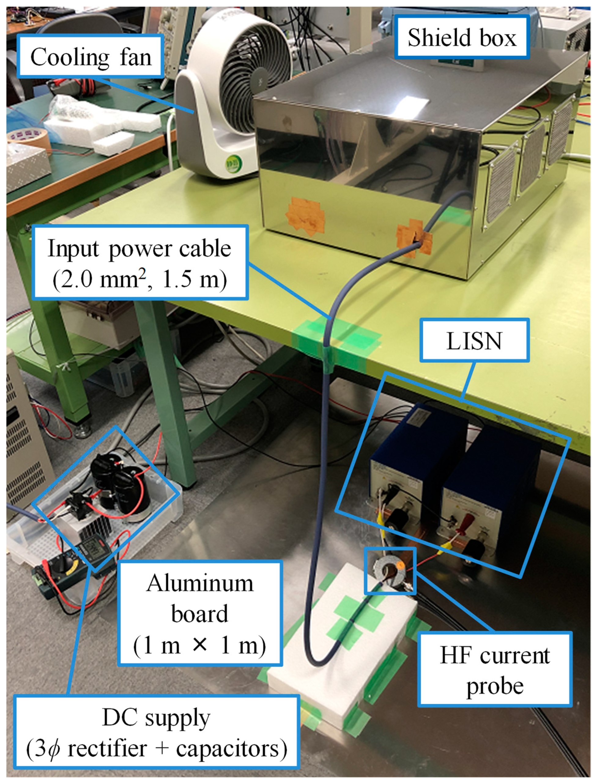
To validate the generation mechanism of the SCM noise, measurements of the CM currents were performed in the laboratory. The configuration of the experimental system for CM current measurements has already been shown in Figure 2. Figure 6 is a picture of the constructed experimental system.

Figure 6.
Experimental setup for measurement of the CM currents in the laboratory.
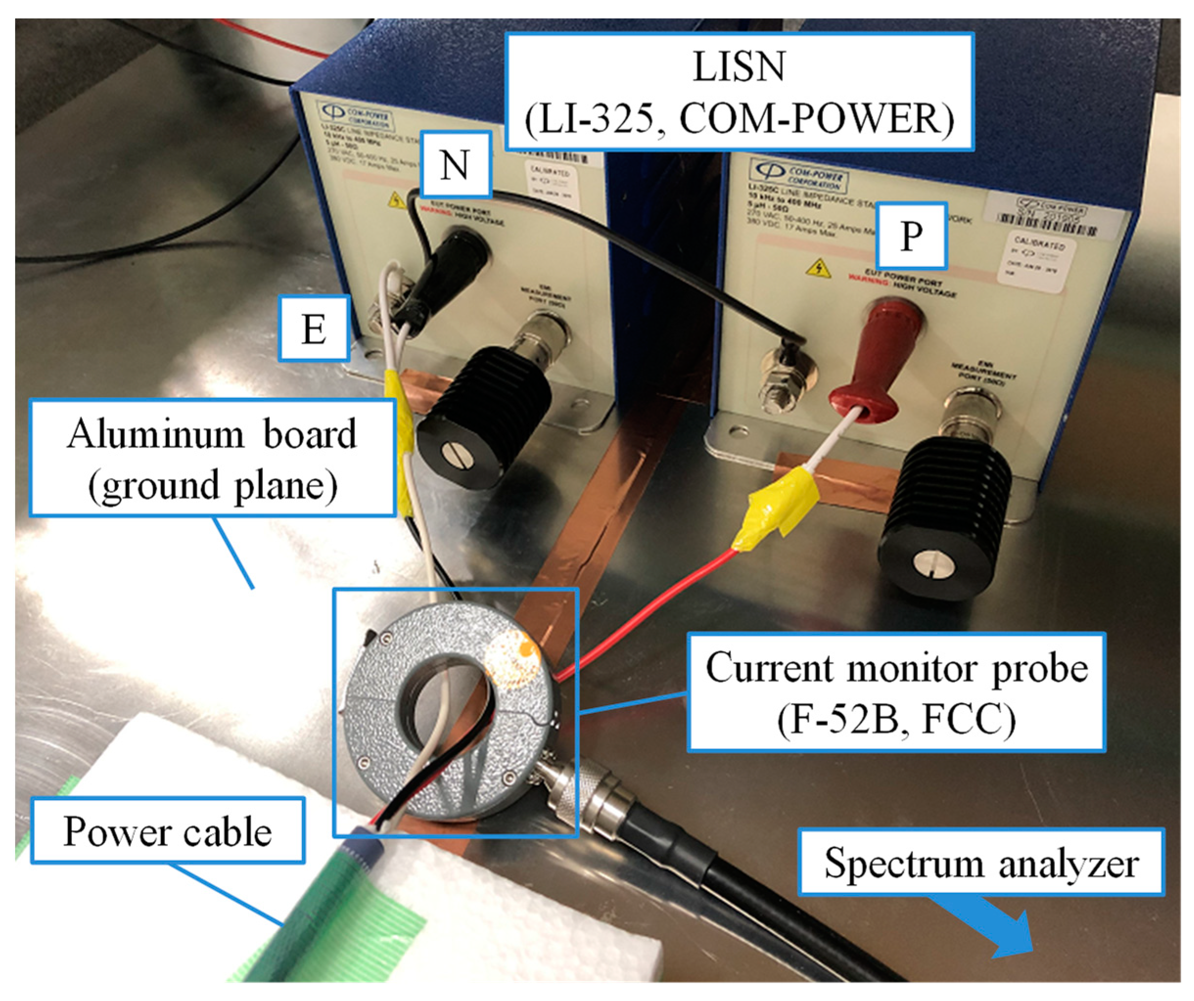
Every measurement in this article was performed when the input DC voltage was 200 V; the switching frequency was 100 kHz; the duty was 0.5; and the output power was 100 W. Dry cell batteries were used to supply the control circuit for preventing the radiated emission from the power supply of the control circuit. A spectrum analyzer (FPL1003, ROHDE&SCHWARZ, Munich, Germany) and current-monitor probe (F-52B, Fischer Custom Communications, Torrance, CA, USA) were used to measure the CM currents. The measured CM current is displayed on the spectrum analyzer as the voltage value. Thus, the measured value is transferred to the current value based on the frequency characteristics of the transfer impedance obtained from the datasheet of the probe. As shown in Figure 7, the PCM current was measured by clamping the power lines P and N together near the LISN with the probe, and the SCM current was measured by clamping the power lines and the ground line E together.

Figure 7.
Measurement point of the CM currents.
Since the measured results were obtained as voltage values in the spectrum analyzer, the measured results were converted to current based on the transformer impedance of the current-monitor probes provided by the developer. Here, the two-winding CMI connected to the PCM is called the primary common-mode inductor (P-CMI), and the three-winding CMI connected to the SCM is called the secondary common-mode inductor (S-CMI). The measurements of CM currents were performed in the frequency range from 30 to 300 MHz when no CMI was connected; the P-CMI was connected; and the S-CMI was connected near the power converter.
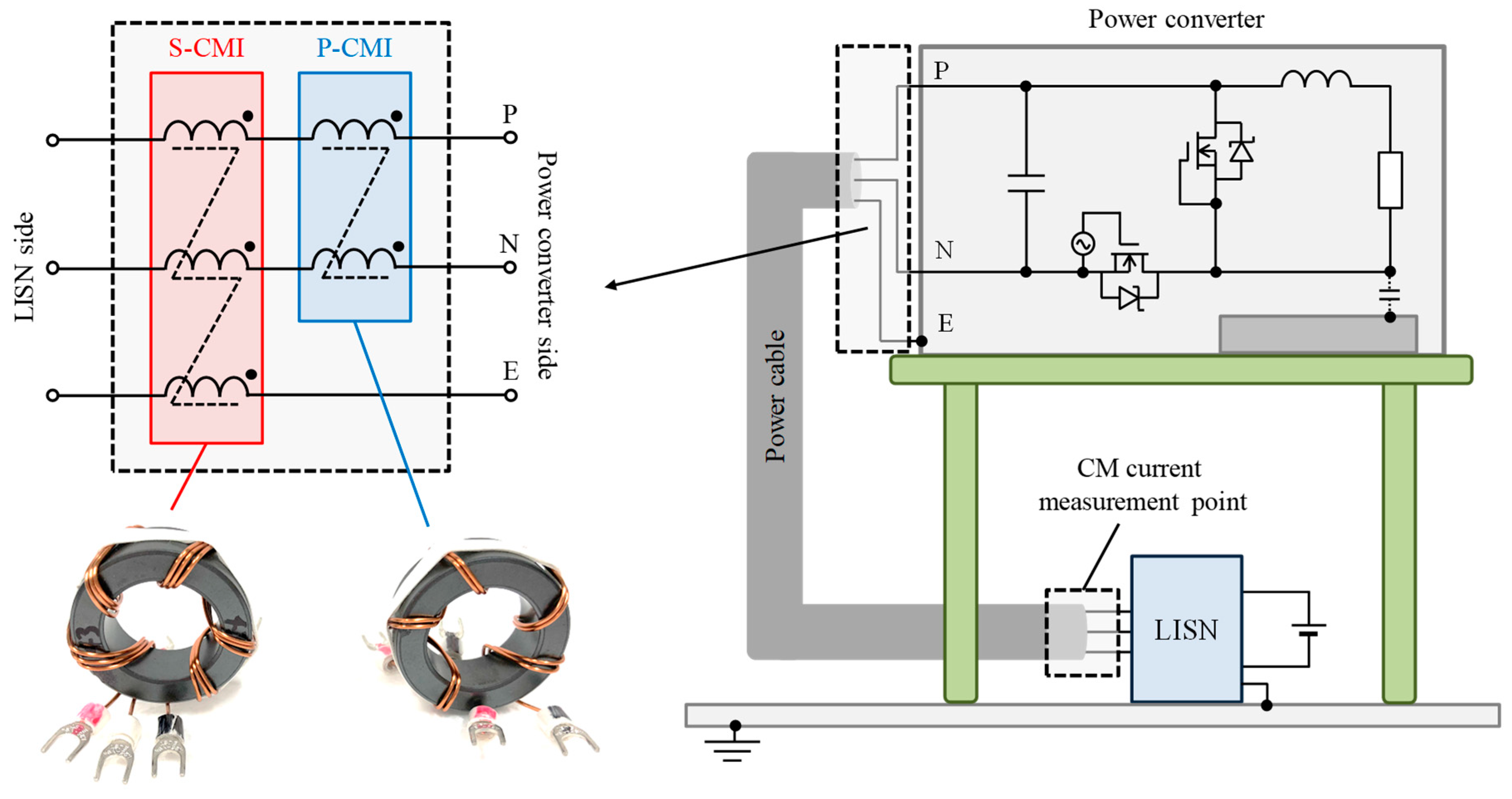
Each CMI was fabricated by applying five turns of multiple windings of the same polarity to a nickel–zinc ferrite core (43 material, model number: 5943002701, Fair-Rite, Singapore) for each noise propagation mode. Figure 8 shows each CMI and a configuration of the entire experimental system when the CMIs are connected.
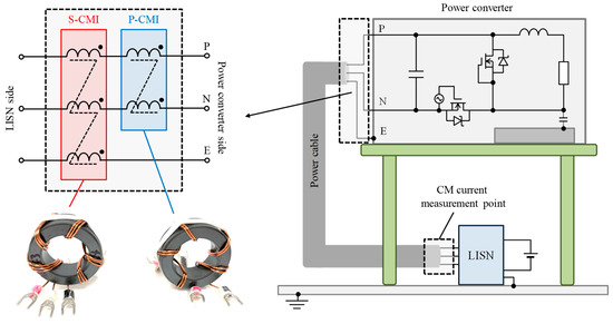
Figure 8.
Configuration of the experimental system when the CMIs are connected.
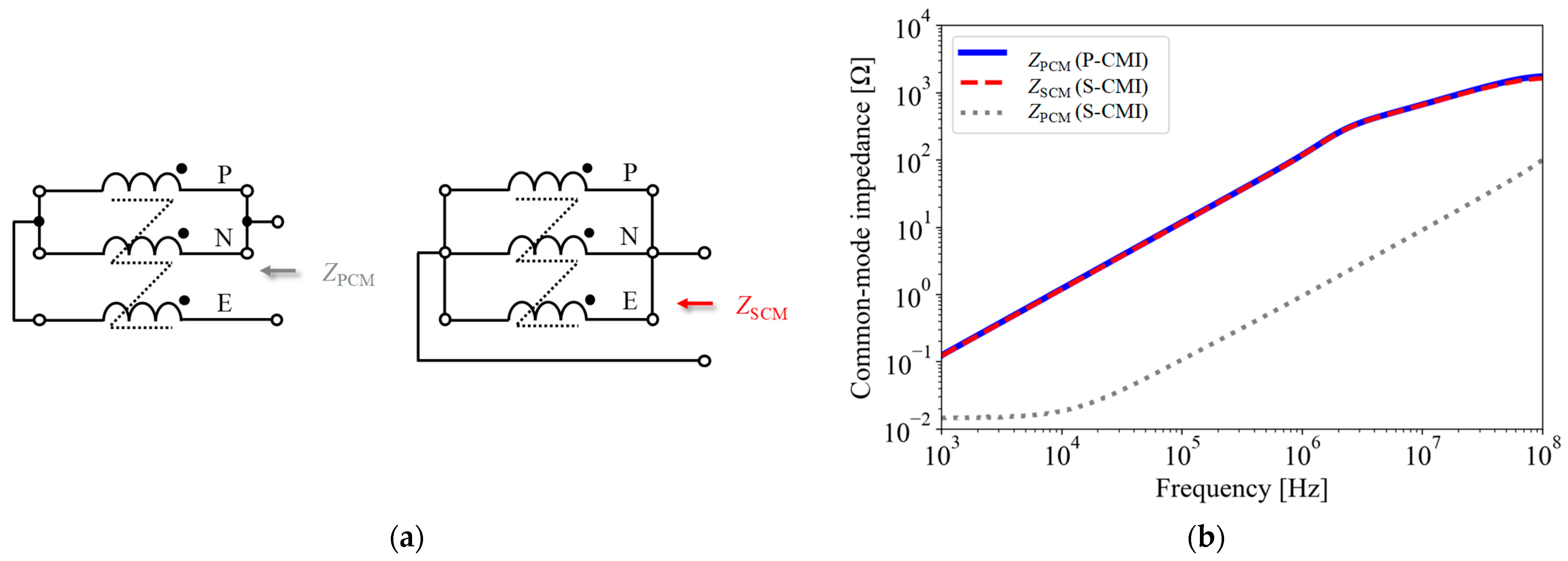
Figure 9 shows the measured frequency characteristics of the PCM and SCM impedances (ZPCM and ZSCM) of each fabricated CMI. The measurements were performed using an impedance analyzer (E4990A, Keysight, Santa Rosa, CA, USA) in the frequency range from 1 kHz to 100 MHz. For the P-CMI, ZPCM was measured by connecting the terminals of the two windings shorted together to the measurement terminals of the impedance analyzer. ZPCM and ZSCM of the fabricated S-CMI were measured according to the connections, as shown in Figure 9a. Figure 9b confirms that the PCM impedance of the P-CMI and the SCM impedance of the S-CMI show similar frequency characteristics due to the equal turn numbers of the two CMIs. Up to about 2 MHz, the impedance increases with a +20 dBΩ/dec slope. Above 2 MHz, the slopes of impedance increase are about +10 dB/Ω due to the complex permeability of the NiZn ferrite core. Note that the PCM impedance of the S-CMI corresponds to the leakage inductance of the S-CMI. The PCM impedance of S-CMI is very small compared to the SCM impedance because of the winding arrangement’s high coupling between the windings. Moreover, it can be confirmed that the winding resistance is dominant from 1 kHz to 10 kHz in the measured PCM impedance of S-CMI.
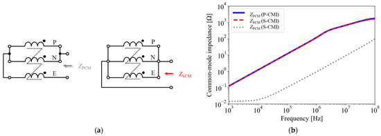
Figure 9.
CM impedance measurements of the fabricated CMIs. (a) Measurement configurations of the S-CMI; (b) measured CM impedances.
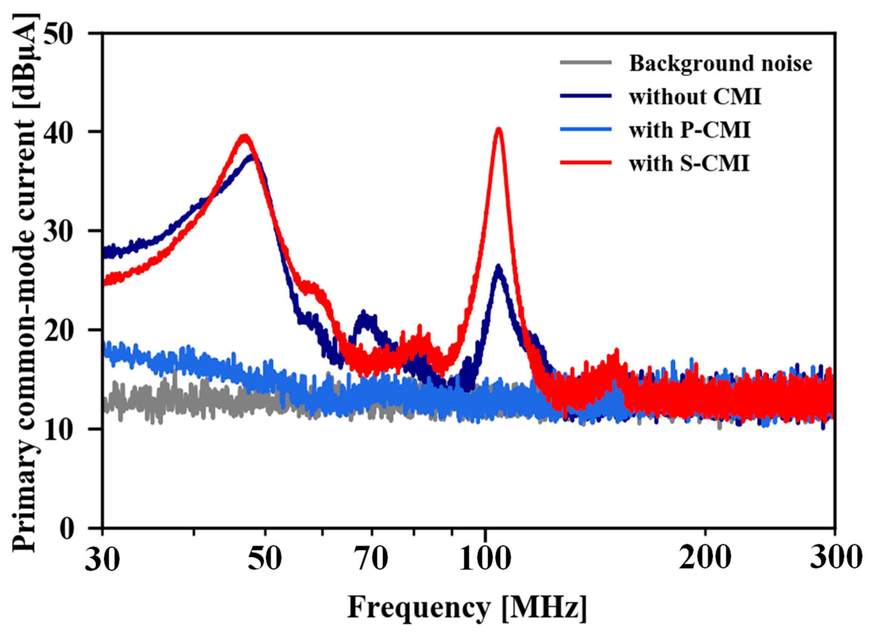
Figure 10 and Figure 11 show the measured PCM and SCM currents. The background noise shown in Figure 10 and Figure 11 was measured when only the cooling fan of the buck converter was operating.

Figure 10.
Measured primary common-mode currents.

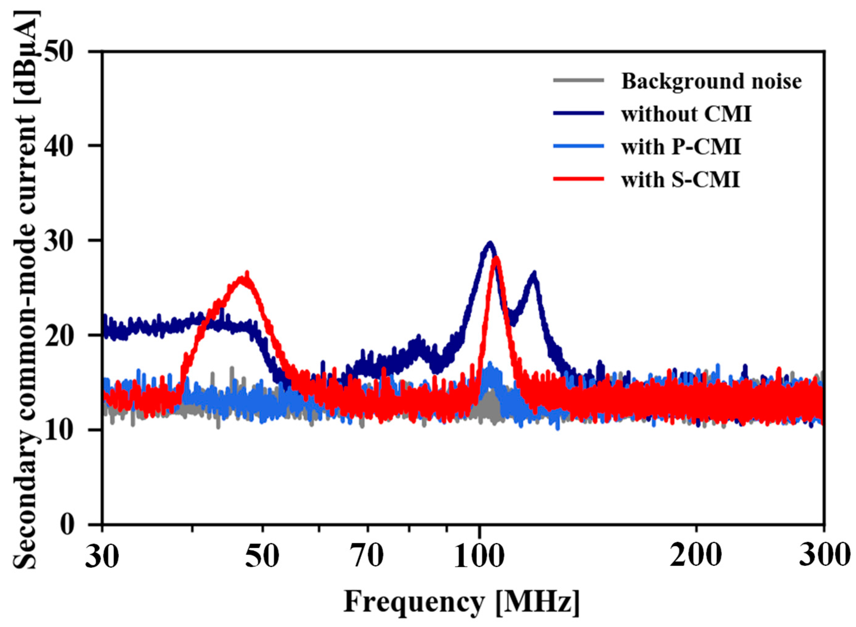
Figure 11.
Measured secondary common-mode currents.
First, Figure 10 shows that the PCM current is almost suppressed to the background noise level over the measured frequency range by connecting the P-CMI near the power converter. This result is because the P-CMI has high impedance for PCM as shown in Figure 9b. On the other hand, since the S-CMI has an insignificant impedance for PCM due to high coupling between the windings, the PCM current was not reduced when the S-CMI was connected. A peak of PCM current is observed at 110 MHz when the CMI is not connected which is possibly caused by the standing wave of the PCM current. The 3/4 wavelength of the 1.5 m power cable is 150 MHz. Considering that the shortening coefficient of the wavelength depends on the cable material, 110 MHz is almost equal to 3/4 wavelength of the power cable. Moreover, an increase in the PCM current at around 110 MHz is confirmed when S-CMI is connected. This is possibly due to the resonance of the leakage inductance and winding stray capacitance of the S-CMI.
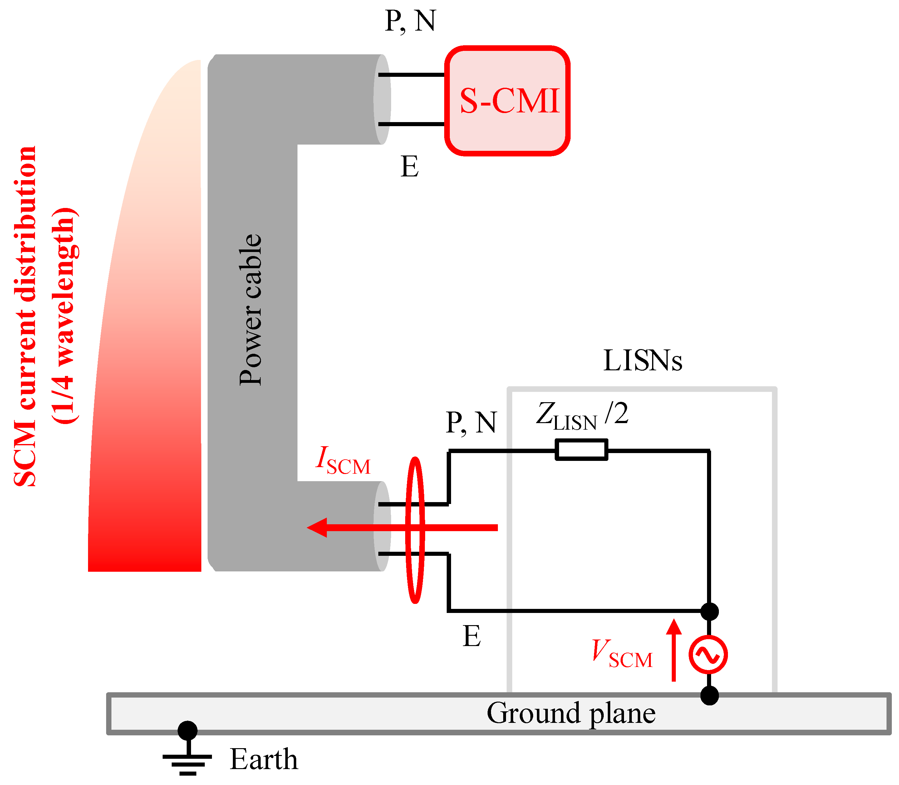
As shown in Figure 4, the power converter side is open to the ground plane and has a significant SCM impedance. Therefore, the standing wave of SCM current is generated in the three-core cable with the power supply side as the antinode and the power converter side as the node. In this case, even if the S-CMI is connected near the power converter, insignificant attenuation is obtained on the SCM current at the frequencies where the power converter side is the node of the SCM current. Therefore, even when the S-CMI is connected near the power converter, as shown in Figure 12, a standing wave of the SCM current similar to those shown in Figure 4 is generated in the three-core cable. Furthermore, the power cable functions as a monopole antenna for the SCM. Therefore, the radiated emission is possibly very large at the frequencies where the standing wave peaks of the SCM current appear. Based on the above discussion, the position of the S-CMI installed and the radiated emissions from the power cable are strongly related. This relationship will be studied in detail in future work.

Figure 12.
Configuration of a monopole antenna constructed when the S-CMI is connected to the three-core cable.
Since the length of the three-core cable connecting the power converter and the LISNs is 1.5 m, the SCM current near the LISN is at maximum at 50 MHz (1/4 wavelength) and 150 MHz (3/4 wavelength). These frequencies are almost equal to 45 MHz and 110 MHz, where large SCM currents were observed in Figure 11, considering the cable’s shortening coefficient of wavelength. As the cable length increases, peaks of SCM current may shift to lower frequencies. Thus, when the buck converter is connected to LISNs with a long cable, the measured peaks of radiated emission may be shifted to lower frequencies.
4.2. Radiated Emission
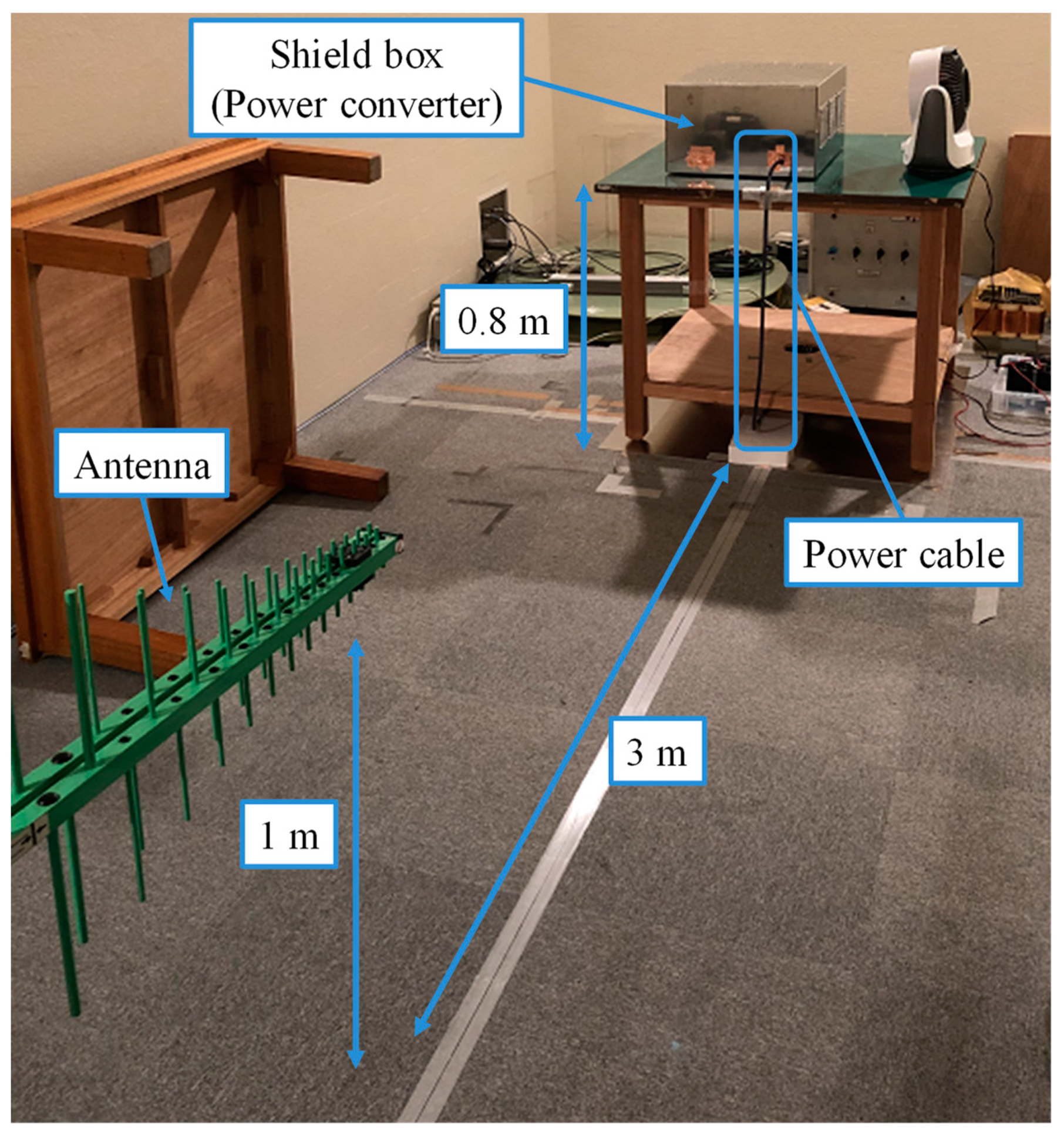
Radiated emission from the experimental system was measured in a semi-anechoic chamber. Figure 13 shows a picture of the experimental setup for radiated emission measurements. The experimental system has the same configuration and layout as the setup for the CM current measurement. As shown in Figure 2, the buck converter and the load are housed in the metal box to prevent radiated emission from the power converter itself. The three-core power cable is placed perpendicular to the ground plane, and the electrical field intensity is measured with a log-periodic antenna 3 m away from the cable. In this experimental setup, the vertical polarization dominates the radiated emission from the cable. Thus, this subsection evaluates only the vertical polarization.

Figure 13.
Experimental setup for measurement of radiated emission in an anechoic chamber.
Figure 14 shows the measured results of radiated emission. Every measurement was performed in the frequency range from 30 MHz to 300 MHz when no CMI was connected; the P-CMI was connected; and the S-CMI was connected near the power converter. Note that the background noise was measured when only the cooling fan was operating.
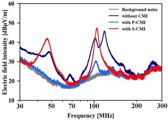
Figure 14.
Measured radiated emission.
Figure 14 shows that the measured radiated emission indicates a similar tendency to the measured result of the SCM current shown in Figure 11. This result clarifies that the SCM current is the dominant source of radiated emission in the experimental system. It can be confirmed from Figure 14 that the radiated emission is suppressed to almost the background noise level when the P-CMI is connected. As described in Section 3, the PCM current and unbalance of the power supply side impedances generate the SCM voltage. The SCM voltage is suppressed because the P-CMI reduces the PCM current effectively. Thus, the connection of the P-CMI can suppress the radiated emission from the cable.
When the S-CMI is connected near the power converter, the significant radiated emissions are measured at around 45 MHz and 110 MHz, where the large SCM current is observed in Figure 11. This result indicates that the S-CMI connected near the power converter cannot suppress the radiated noise significantly at frequencies where the SCM current is the node at the power converter side. On the other hand, the measured radiated emission is almost equal to the background noise at other frequencies. These results correlate very well with the measured result of the SCM current, as shown in Figure 11, and demonstrate the generation mechanism of radiated emission described in Section 4.1.
5. Conclusions
In this article, the generation mechanism of radiated emission was experimentally investigated for the simple experimental system consisting of the buck converter. The contribution of this article is to clarify that the SCM noise is the radiated emission source in power converters with ground wires, and that the PCM current and the unbalance of the power supply side impedances experimentally cause the SCM noise.
The radiated emission generation mechanism demonstrated in this article is widely applicable to power converters with ground wires or shielded cables. By applying effective radiated emission suppression techniques, based on the result of this article, the time and cost of suppressing radiated emission are expected to be reduced. For example, clamp-type ferrite cores have been widely used to suppress radiated emissions from power cables. Based on the results obtained in this article, it is difficult to suppress the radiated emission at frequencies where the SCM current is the node when the cable, including the ground wire, is clamped together near the PCM noise source. In other words, when using clamp-type ferrite cores, it is essential to consider the appropriate insertion position for each noise propagation mode. Future studies will investigate effective CMI placement and supply side impedance balancing to suppress radiated emissions.
Funding
This research received no external funding.
Institutional Review Board Statement
Not applicable.
Informed Consent Statement
Not applicable.
Data Availability Statement
Not applicable.
Acknowledgments
The author would like to thank S. Ogasawara of Hokkaido University, for supporting this article through providing his expertise in the electromagnetic compatibility of power electronics.
Conflicts of Interest
The author declares no conflict of interest.
Nomenclature
| IDM | Differential-mode current |
| IPCM | Primary common-mode current |
| ISCM | Secondary common-mode current |
| VE | Voltage potential of the terminal E for the ground |
| VN | Voltage potential of the terminal N for the ground |
| VP | Voltage potential of the terminal P for the ground |
| VPCM | Primary common-mode voltage |
| VSCM | Secondary common-mode voltage |
| ZDM | Differential-mode impedance |
| ZE | Impedance of the ground wire E |
| ZG | Impedance between the terminal E and the ground plane |
| ZLISN | Impedance of the line impedance stabilization network |
| ZN | Impedance of the power line N |
| ZP | Impedance of power the line P |
| ZPCM | Primary common-mode impedance |
| ZSCM | Secondary common-mode impedance |
References
- Sengupta, S.; Kumar, A.; Tiwari, S. Transient stability enhancement of a hybrid Wind-PV farm incorporating a STATCOM. In Proceedings of the 2018 3rd IEEE International Conference on Recent Trends in Electronics, Information & Communication Technology (RTEICT), Bangalore, India, 18–19 May 2018; pp. 1574–1580. [Google Scholar]
- Sinha, S.; Chandel, S.S.; Malik, P. Investigation of a building-integrated solar photovoltaic-wind-battery hybrid energy system: A case study. Int. J. Energy Res. 2021, 45, 21534–21539. [Google Scholar] [CrossRef]
- Biela, J.; Schweizer, M.; Waffler, S.; Kolar, J.W. SiC versus Si—Evaluation of Potentials for Performance Improvement of Inverter and DC–DC Converter Systems by SiC Power Semiconductors. IEEE Trans. Ind. Electron. 2011, 58, 2872–2882. [Google Scholar] [CrossRef]
- Han, D.; Li, S.; Wu, Y.; Sarlioglu, B. Comparative Analysis on Conducted CM EMI Emission of Motor Drives: WBG Versus Si Devices. IEEE Trans. Ind. Electron. 2017, 64, 8353–8363. [Google Scholar] [CrossRef]
- Engelmann, D.G.; Sewergin, A.; Neubert, M.; De Doncker, R.W. Design Challenges of SiC Devices for Low- and Medium-Voltage DC-DC Converters. IEEJ J. Ind. Appl. 2019, 8, 505–511. [Google Scholar] [CrossRef]
- Zhang, B.; Wang, S. A Survey of EMI Reserch in Power Electronics Systems with Wide-Bandgap Semiconductor Devices. IEEE J. Emerg. Sel. Topics Powe Electron. 2020, 8, 626–643. [Google Scholar] [CrossRef]
- Takahashi, S.; Wada, K.; Ayano, H.; Ogasawara, S.; Shimizu, T. Review of Modeling and Suppression Techniques for Electromagnetic Interference in Power Conversion Systems. IEEJ J. Ind. Appl. 2022, 11, 7–19. [Google Scholar] [CrossRef]
- Ogasawara, S.; Akagi, H. Modeling and Damping of High-Frequency Leakage Currents in PWM Inverter-Fed AC Motor Drive Systems. IEEE Trans. Ind. Appl. 1996, 32, 1105–1114. [Google Scholar] [CrossRef]
- Akagi, H.; Hasegawa, H.; Doumoto, T. Design and Performance of a Passive EMI Filter for Use with a Voltage-Source PWM Inverter Having Sinusoidal Output Voltage and Zero Common-Mode Voltage. IEEE Trans. Power Electron. 2004, 19, 1069–1076. [Google Scholar] [CrossRef]
- Ogasawara, S.; Ayano, H.; Akagi, H. An Active Circuit for Cancellation of Common-Mode Voltage Generated by a PWM Inverter. IEEE Trans. Power Electron. 1998, 13, 835–841. [Google Scholar] [CrossRef]
- Takahashi, S.; Maekawa, S. Attenuation Characteristics of the Input/Output Coupling Passive EMI Filter on Conducted Emission in Motor Drive Systems. IEEJ J. Ind. Appl. 2022, 11, 709–710. [Google Scholar] [CrossRef]
- Wang, A.; Zhang, F.; Gao, T.; Wu, Z.; Li, X. Integrated CM Inductor for Both DC and AC Noise Attenuation in DC-Fed Motor Drive Systems. IEEE Trans. Power Electron. 2023, 38, 510–522. [Google Scholar] [CrossRef]
- Julian, A.L.; Oriti, G.; Lipo, T.A. Elimination of Common-Mode Voltage in Three-Phase Sinusoidal Power Converters. IEEE Trans. Power Electron. 1999, 14, 982–989. [Google Scholar] [CrossRef]
- Han, D.; Morris, C.T.; Sarlioglu, B. Common-Mode Voltage Cancellation in PWM Motor Drives With Balanced Inverter Topology. IEEE Trans. Ind. Electron. 2017, 64, 2683–2688. [Google Scholar] [CrossRef]
- Han, D.; Lee, W.; Li, S.; Sarlioglu, B. New Method for Common Mode Voltage Cancellation in Motor Drives: Concept, Realization, and Asymmetry Influence. IEEE Trans. Power Electron. 2018, 33, 1188–1201. [Google Scholar] [CrossRef]
- Xie, L.; Yuan, X. Common-Mode Current Reduction at DC and AC Sides in Inverter Systems by Passive Cancellation. IEEE Trans. Power Electron. 2021, 36, 9069–9079. [Google Scholar] [CrossRef]
- Xie, L.; Yuan, X.; Zhu, H.; Lo, Y.-K. Common-Mode Voltage Cancellation for Reducing the Common-Mode Noise in DC–DC Converters. IEEE Trans. Ind. Electron. 2021, 68, 3887–3897. [Google Scholar] [CrossRef]
- Xie, L.; Yuan, X. Non-Isolated DC-DC Converters With Low Common-Mode Noise by Using Split-Winding Configuration. IEEE Trans. Power Electron. 2022, 37, 452–461. [Google Scholar] [CrossRef]
- Hockanson, D.M.; Drewniak, J.L.; Hubing, T.H.; Van Doren, T.P.; Fei, S.; Wilhelm, M.J. Investigation of Fundamental EMI Source Mechanisms Driving Common-Mode Radiation from Printed Circuit Boards with Attached Cables. IEEE Trans. Electromagn. Compat. 1996, 38, 557–566. [Google Scholar] [CrossRef]
- Roc’h, A.; Leferink, F. Nanocrystalline Core Material for High-Performance Common Mode Inductors. IEEE Trans. Electromagn. Compat. 2012, 54, 785–791. [Google Scholar] [CrossRef]
- Laour, M.; Tahmi, R.; Vollaire, C. Modeling and Analysis of Conducted and Radiated Emissions due to Common Mode Current of a Buck Converter. IEEE Trans. Electromagn. Compat. 2017, 59, 1260–1267. [Google Scholar] [CrossRef]
- Takahashi, S.; Ogasawara, S.; Orikawa, K.; Takemoto, M.; Tamate, M. An Active Common-Mode Filter for Reducing Radiated Noise from Power Cables. In Proceedings of the 2017 IEEE 3rd International Future Energy Electronics Conference and ECCE Asia (IFEEC 2017—ECCE Asia), Kaohsiung, Taiwan, 3–7 June 2017; pp. 1753–1758. [Google Scholar]
- Yao, J.; Li, Y.; Zhao, H.; Wang, S.; Wang, Q.; Lu, Y.; Fu, D. Modeling and Reduction of Radiated Common Mode Current in Flyback Converters. In Proceedings of the 2018 IEEE Energy Conversion Congress and Exposition (ECCE), Portland, OR, USA, 23–27 September 2018; pp. 6613–6620. [Google Scholar]
- Zhang, Y.; Wang, S.; Chu, Y. Investigation of Radiated Electromagnetic Interference for an Isolated High-Frequency DC–DC Power Converter With Power Cables. IEEE Trans. Power Electron. 2019, 34, 9632–9643. [Google Scholar] [CrossRef]
- Yao, J.; Wang, S.; Luo, Z. Modeling, Analysis, and Reduction of Radiated EMI Due to the Voltage Across Input and Output Cables in an Automotive Non-Isolated Power Converter. IEEE Trans. Power Electron. 2022, 37, 5455–5465. [Google Scholar] [CrossRef]
- Ma, Z.; Wang, S.; Sheng, H.; Lakshmikanthan, S. Modeling, Analysis and Mitigation of Radiated EMI Due to PCB Ground Impedance in a 65 W High-Density Active-Clamp Flyback Converter. IEEE Trans. Ind. Electron. 2023, 70, 12267–12277. [Google Scholar] [CrossRef]
- Nobunaga, T.; Toyota, Y.; Iokibe, K.; Koga, L.R.; Watanabe, T. Evaluation of Pigtail Termination of STP Cable Using Model Equivalent Circuit of Four-Conductor Transmission Systems. In Proceedings of the 2013 International Symposium on Electromagnetic Theory, Hiroshima, Japan, 23–24 May 2013; pp. 222–225. [Google Scholar]
- Vincent, M.; Klingler, M.; Riah, Z.; Azzouz, Y. Influence of Car Body Materials on the Common-Mode Current and Radiated Emissions Induced by Automotive Shielded Cables. In Proceedings of the 2015 IEEE International Symposium on Electromagnetic Compatibility (EMC), Dresden, Germany, 16–22 August 2015; pp. 726–731. [Google Scholar]
- Zhang, N.; Kim, J.; Nah, W. Novel Extended Mixed-Mode S-Parameters and Mode Conversion of Four-Conductor Lines. In Proceedings of the 2015 Asia-Pacific Symposium on Electromagnetic Compatibility (APEMC), Taipei, Taiwan, 25–29 May 2015; pp. 712–715. [Google Scholar]
- Instruction Manual for Line Impedance Stabilization Network Model LI-325C 10 kHz to 400 MHz. Available online: https://documentation.com-power.com/pdf/LI-325C-2.pdf (accessed on 22 October 2023).
- Foissac, M.; Schanen, J.; Vollaire, C. “Black Box” EMC Model for Power Electronics Converter. In Proceedings of the 2009 IEEE Energy Conversion Congress and Exposion, San Jose, CA, USA, 20–24 September 2009; pp. 3609–3615. [Google Scholar]
- Bishnoi, H.; Baisden, A.C.; Mattavelli, P.; Boroyevich, D. Analysis of EMI Terminal Modeling of Switched Power Converters. IEEE Trans. Power Electron. 2012, 27, 3924–3933. [Google Scholar] [CrossRef]
- Amara, M.; Vollaire, C.; Ali, M.; Costa, F. Black Box EMC Modeling of a Three Phase Inverter. In Proceedings of the 2018 International Symposium on Electromagnetic Compatibility (EMC EUROPE), Amsterdam, The Netherlands, 27–30 August 2018; pp. 642–647. [Google Scholar]
- Yao, J.; Li, Y.; Zhao, H.; Wang, S. Design of CM Inductor Based on Core Loss for Radiated EMI Reduction in Power Converters. In Proceedings of the 2019 IEEE Applied Power Electronics Conference and Exposition (APEC), Long Beach, CA, USA, 25–29 February 2019; pp. 2673–2680. [Google Scholar]


Disclaimer/Publisher’s Note: The statements, opinions and data contained in all publications are solely those of the individual author(s) and contributor(s) and not of MDPI and/or the editor(s). MDPI and/or the editor(s) disclaim responsibility for any injury to people or property resulting from any ideas, methods, instructions or products referred to in the content. |
© 2023 by the author. Licensee MDPI, Basel, Switzerland. This article is an open access article distributed under the terms and conditions of the Creative Commons Attribution (CC BY) license (https://creativecommons.org/licenses/by/4.0/).