Abstract
To verify the dynamic model of a paddy-field laser grader and solve the problem of the unstable high-speed operation of the grader, a method for measuring the absolute pose parameters of a moving rigid body using a monocular camera is proposed. The proposed method does not require calibration beforehand. Using more than six non-coplanar control points symmetrically arranged in the rigid-body and world coordinate systems, the matrices of rotation and translation between the camera and two coordinate systems are obtained and the absolute pose of the rigid body is measured. In this paper, formulas of the absolute pose measurement of a moving rigid body are deduced systematically and the complete implementation is presented. Position and attitude measurement experiments carried out on a three-axis precision turntable show that the average absolute error in the attitude angle of a moving rigid body measured by an uncalibrated camera at different positions changes by no more than 0.2 degrees. An analysis of the three-dimensional coordinate errors of the centroid of a moving rigid body shows little deviation in measurements taken at the three camera positions, with the maximum deviation of the average absolute error being 0.53 cm and the maximum deviation of the standard deviation being 0.66 cm. The proposed method can measure the absolute pose of a rigid body and is insensitive to the position of the camera in the measurement process. This work thus provides guidance for the repeated measurement of the absolute pose of a moving rigid body using a monocular camera.
1. Introduction
A laser grader faces the problem of unstable high-speed operation during the actual promotion process in a paddy field. Specifically, when the grader is operating at high speed, the leveling accuracy and overall smoothness of the machine are poor [1]. Starting from the basic structure of paddy-field graders, studying their dynamic models, improving the accuracy of control algorithms, and optimizing the design of mechanical structures are effective ways to solve this problem. The laser grader in a paddy field is a rigid flexible coupling multibody system, and the verification of its dynamic model often requires the measurement of the rigid dynamic parameters of the mechanical system, including the positions of points (to obtain the velocity and acceleration) and the attitude angle of the rigid body (to obtain the angular velocity and angular acceleration) [2]. These parameters often need to be repeatedly measured in different time periods to verify the performance of multibody systems.
Non-contact measurement technology for determining trajectory and attitude changes of rigid moving targets has become a focus of research with the rapid advancement of science and technology [3,4]. Visual technologies for measuring the pose of a target are widely used in obtaining motion parameters and mainly involve monocular, binocular, and multi-ocular measurements, with each technology having its advantages and disadvantages. However, whereas binocular and multi-ocular measurements suffer from a small field of view and difficulties in stereo matching, monocular measurements have a simple structure, large field of view, strong real-time performance, and good accuracy. Monocular systems are thus used widely to measure parameters of rigid-body motion [5,6,7,8].
There are two types of monocular visual measurement of pose according to the features selected, namely measurements of cooperative targets [9,10,11] and measurements of non-cooperative targets [12,13,14]. Among them, the spatial constraint relationship between target feature points in cooperative target pose measurement is controllable, which to some extent limits the application scope but reduces the difficulty of feature extraction, improves the extraction accuracy, and reduces the complexity of the pose calculation. At present, research on cooperative target measurement methods has focused mainly on cooperative target design, feature extraction, pose calculation methods, and pose calculation errors [15,16,17,18,19]. However, most of the results are based on calibrated camera parameters and there has been little research on the pose estimation problem of cameras with varying focal lengths. In some practical problems, such as the measurement of multiple rigid-body motion parameters addressed in this article, the internal parameters of the camera need to be frequently adjusted and changed, and there are many factors that affect the calibration accuracy of the internal parameters of a camera. It is difficult to accurately determine the internal parameters in the absence of standard equipment. Therefore, research on uncalibrated camera pose estimation technology is also important. The main methods of solving the pose measurement problem of uncalibrated cameras are the classic two-step method [20], direct linear transform (DLT) method [21], Zhengyou Zhang’s calibration method [22], P4P and P5P methods [23], and AFUFPnP method [24] proposed by Tsai and others. The two-step method is not suitable for dynamic measurement. P4P and P5P methods face noise sensitivity problems because they use fewer control points to estimate internal and external parameters. Zhengyou Zhang’s calibration method requires the installation of a planar chessboard on the measured object to ensure accuracy, which is inconvenient in the case of a moving rigid body. The AFUFPnP method is a pose estimation method based on the EPnP [25] and POSIT [26] algorithms. This method has high pose estimation accuracy and calculation efficiency but low execution efficiency.
In terms of the real-time measurement of the spatial target position and pose using monocular cameras, there have been many studies [27,28] on the pose measurement of robots and aircraft, including studies on target design, the feature extraction of marker points, methods of measuring the positions and attitude angles of cooperative targets, and methods of measuring the positions and attitude angles of non-cooperative targets. Research on visual pose measurement technology in the literature [29] has mainly focused on algorithms, with much success. An algorithm was successfully applied to the Chinese space laboratory Tiangong-2, accurately guiding the robotic arm to complete various spatial experimental tasks, such as grasping floating objects, disassembling insulation materials, screwing electrical connectors, and screwing electric tools. The NASA Insight Mars probe [30], equipped with BMW markers on a seismometer to measure the attitude of the Mars probe relative to a seismometer, was launched in May 2018. The above research has mainly been applied to attitude measurements of aircraft and spacecraft, and there have been few reports on attitude measurements of agricultural machinery. Reference [2] analyzed the mechanism and modeled the dynamics of a rigid–flexible integrated leveling shovel assembly of a paddy-field laser leveling machine. Two high-speed cameras and matching high-speed image analysis software were used to measure the center of mass position and attitude angle of the leveling shovel, thus verifying the dynamic model simulation results. Although this method provides parameter measurements, it requires two high-speed cameras. In addition, owing to the limitations of high-speed image analysis software, the method can simultaneously measure the motion changes of only five points, which is far from meeting the requirements of parameter measurements.
Against the above background, this article combines the foundations of previous research on pose measurement to theoretically derive a method of measuring the absolute pose of a moving rigid body and presents a complete implementation of the method. The method is validated in terms of its feasibility and experimental repeatability for different positional accuracies using a high-speed camera with a variable focal length.
2. Theoretical Derivation of Methods
2.1. Principle of the Absolute Pose Measurement for a Rigid Body
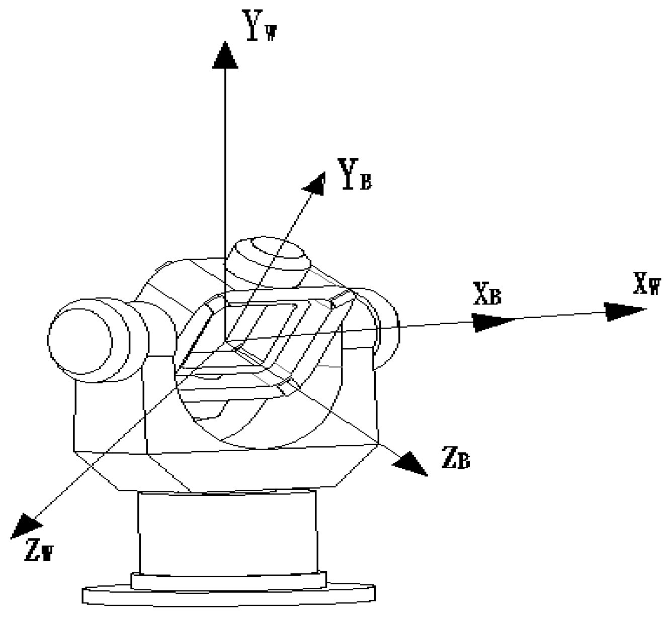
As shown in Figure 1, body and world rigid bodies move relative to one another in space. For the convenience of expression, the body coordinate system OB-XBYBZB, world coordinate system OW-XWYWZW, and camera coordinate system OC-XCYCZC are, respectively, denoted B, W, and C hereafter. We let P and Q denote physical points on the body and world rigid bodies, respectively. We use superscripts to distinguish the coordinate values of the physical points P and Q in the different coordinate systems and subscripts to distinguish different points on the rigid body. For example, represents the coordinate values of the P3 point on the body rigid body in the W system. We use minuscule letters to represent pixel points, e.g., p represents the pixel points projected by physical point P on the image. R and T represent conversion relationships between coordinate systems, where the superscript is used to represent the target coordinate system in the conversion and the subscript is used to represent the starting coordinate system, e.g., is the rotation matrix for conversion from the C system to the W system, and is the translation matrix for the conversion from the B system to the W system.
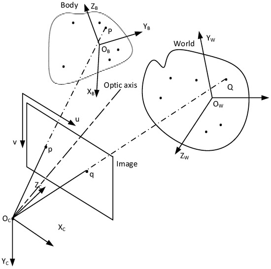
Figure 1.
Principle of the absolute pose measurement for a rigid body using a monocular camera.
The aim of this article is to measure the motion pose of a rigid body in the B system relative to the W system, and the real-time spatial coordinate of the center of mass P of the B-system rigid body in the W system.
The imaging projection formulas are
Here, is the ratio of two vector modes, representing the spatial coordinates of the pixel point p in the C system.
It follows from (1) and (2) that
The motion pose of the rigid body can be solved by , if
According to reference [31], the attitude angle of a rigid body is
Here, , and are the rotation angles around the Z, Y, and X axes, with the order of rotation being Z, Y, and X.
It is seen from (3) and (4) that for and , , , and need to be determined. and are determined from the control points on the W-system rigid body whereas and are determined from the control points on the B-system rigid body. The absolute pose problem of a moving rigid body is thus transformed into a problem of solving the rotation and translation matrices.
2.2. Implementation Steps of the Measurement Method
Figure 2 is a flowchart of the method of measuring the rigid-body pose derived in Section 2.1.
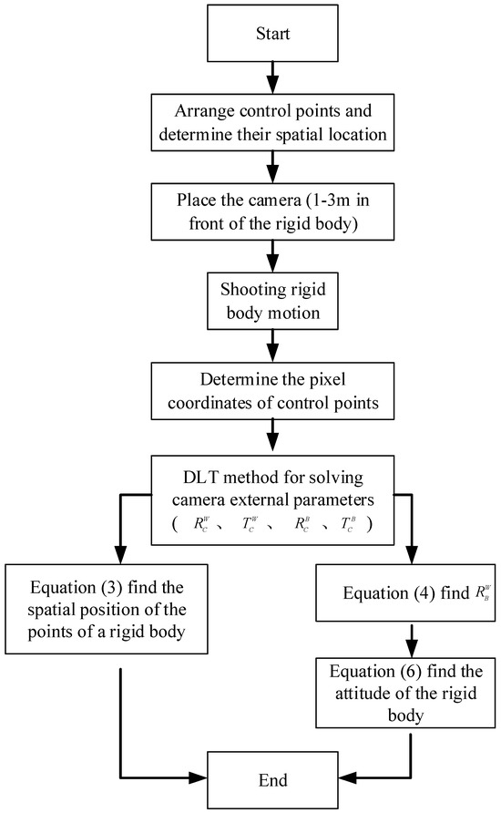
Figure 2.
Flow chart of the method of measuring the rigid-body pose.
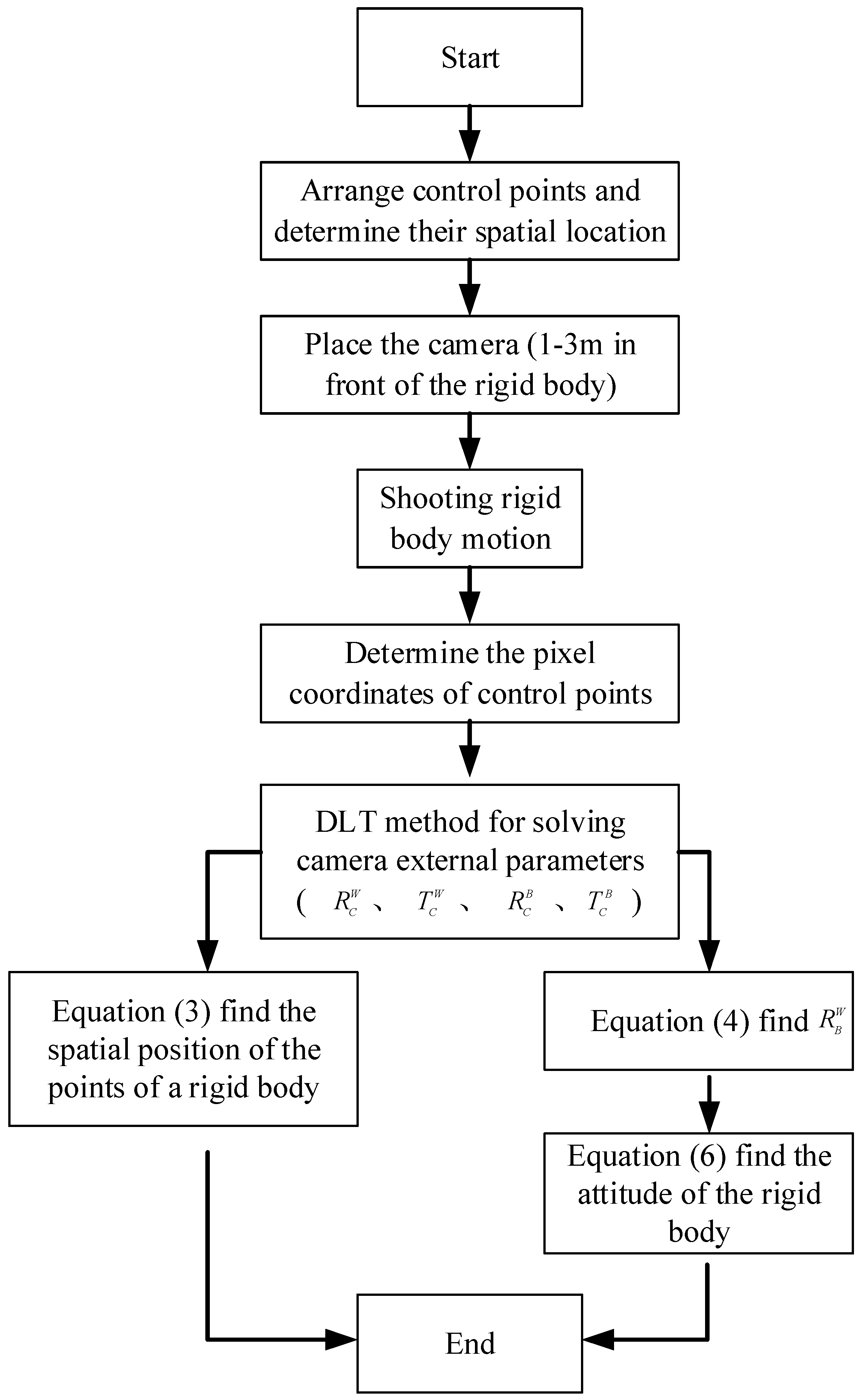
The measurement of the pose parameters of the rigid body involves the following steps. Groups of control points, with each group having more than six non-coplanar points, are first arranged in the W and B systems. R and T for the W–C and B–C conversions are then calibrated and calculated to determine the coordinates of the B-system control points in the W system and to calculate the attitude changes of the B-system rigid body. Finally, the other parameters are measured.
2.3. Determination of the Rotation and Translation Matrices
This paper considers a high-speed camera with a variable focal length. To facilitate repeated experiments, a DLT [32] camera calibration method providing simple operation and high calculation efficiency is adopted to obtain the camera rotation and translation matrices. The DLT method does not require an approximate initial value of the internal orientation element (i.e., it does not require the manual calculation of the initial value in contrast with other space rendezvous algorithms) and is suitable for the calibration processing of non-metric digital cameras.
As shown in Figure 1, N (N ≥ 6) control points are arranged on each of the B and W series. Taking the control points on the body rigid body as an example, if the spatial coordinates are, the corresponding pixel coordinates are. It follows from the collinearity equation of the DLT method that
where denotes coefficients representing the camera’s internal and external parameters.
Equation (7) shows that for the 11 unknowns, at least 6 points are required to determine the 11 values. As the number of equations is greater than the number of unknowns, the least-squares method is used to solve for L and thus obtain the external parameters of the camera.
The constraint conditions of the rotation matrix are not fully considered in obtaining the results using the proposed method, and the error in the results is thus bound to be large. To improve the accuracy, this paper uses the Gauss–Newton iterative method to solve the 11 L equations and 6 constraint equations of the rotation matrix iteratively and then applies singular value decomposition to the obtained rotation matrix. If , then . Similarly, and can be determined. After this processing, the estimated attitude matrix strictly meets the inherent constraints of the rotation matrix, and the estimation error is effectively reduced.
3. Experiments and Data Analysis
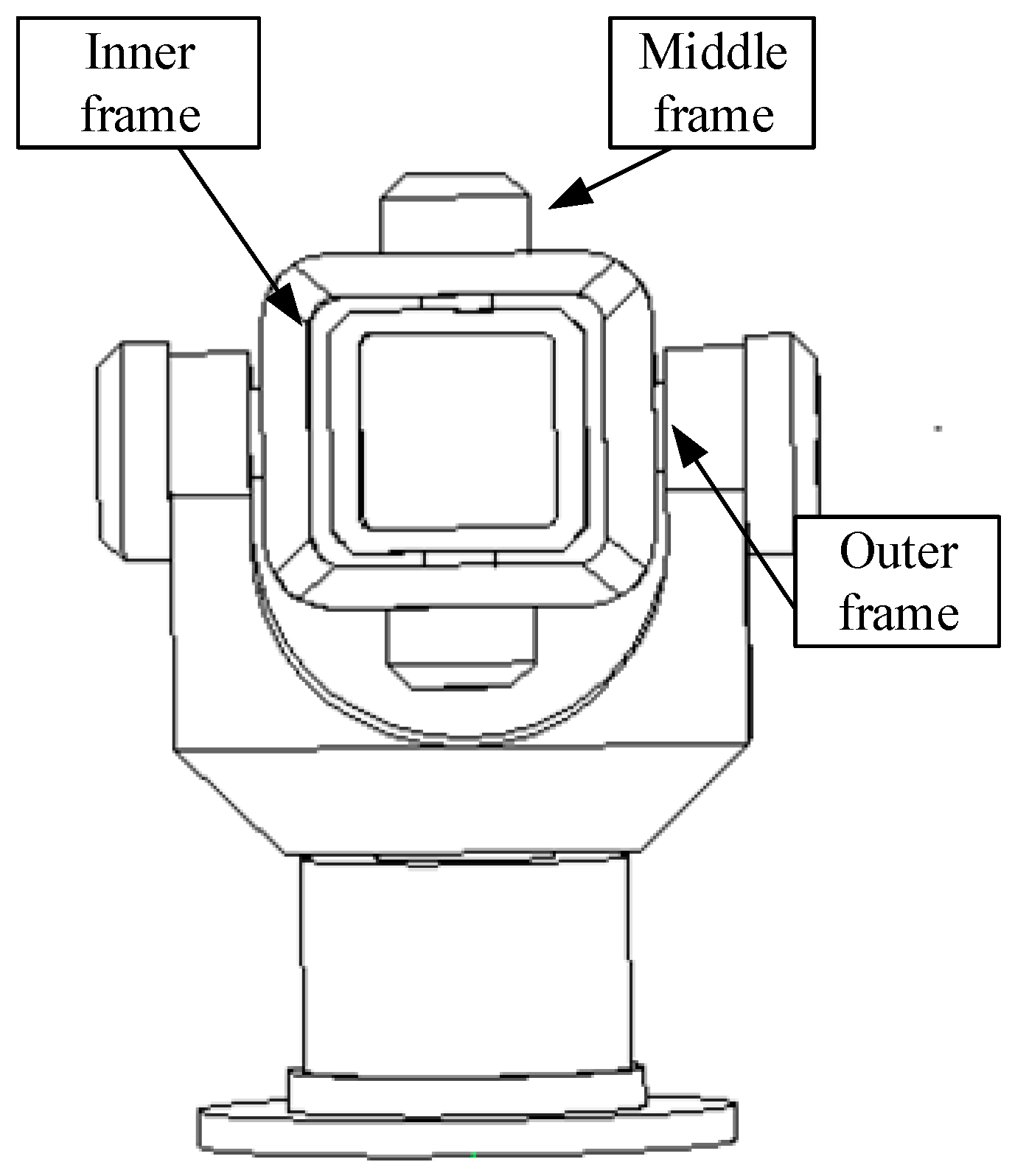
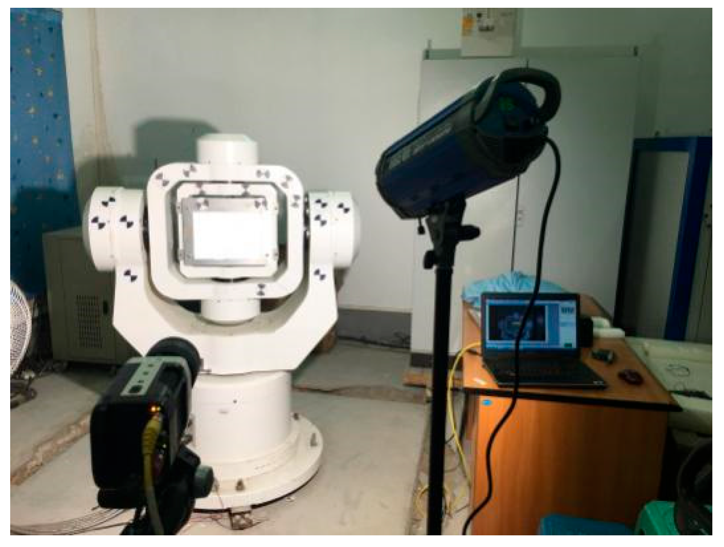
The experimental platform used in this study mainly comprised a three-axis turntable and a camera. The SGT320E three-axis turntable had an accuracy of 0.0001 degrees and a mechanical structure in which a U-shaped outer frame rotated around the azimuth axis, an O-shaped middle frame rotated around the pitch axis, and an O-shaped inner frame rotated around the transverse roller axis. The outer frame, middle frame, and inner frame can all be considered rigid bodies, as shown in Figure 3. The three axes simultaneously had speed, position, and sinusoidal oscillation modes and did not interfere with each other, enabling the high-precision measurement of the pose. A Phantom M310 high-speed camera, produced by Vision Research in the United States, was used. The camera had adjustable resolution, shooting speed, and exposure time. The camera sensor size was 25.6 mm × 16.0 mm, and the camera resolution was 1280 × 800, giving a pixel size of 20 μm × 20 μm. The focal length of the lens was adjustable within the range of 24–85 mm, the shooting speed was 1000 frames/s, and the f-stop was f/2.8. Two 300 W shooting lights with illumination up to 39,800 lux were used to ensure the brightness of shooting at any time.
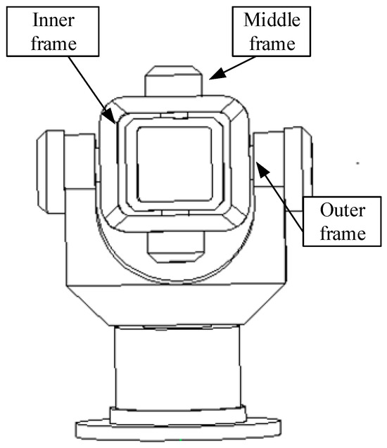
Figure 3.
Schematic of the overall structure of the turntable.
3.1. Establishment of the Coordinate System and Arrangement of Control Points
For the convenience of arranging control points, the inner frame of the turntable was locked and formed a body rigid body with the middle frame, whereas the outer frame was a world rigid body. The origins of the B and W systems were both set at the center of the turntable. According to the construction of the turntable, this point was also the center of mass of the body rigid body, as shown in Figure 4. Figure 5 shows the scene of the experiment, which truly reflects the layout of each marking point. Eight control points were arranged on the body rigid body (i.e., the middle frame) and eight control points were arranged on the world rigid body (i.e., the outer frame).
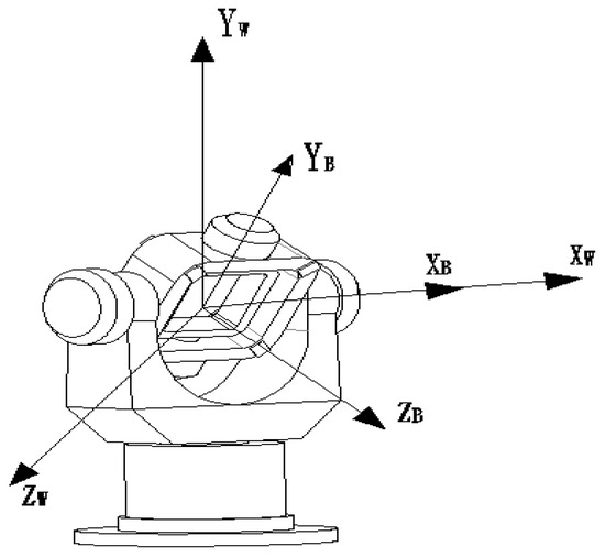
Figure 4.
Coordinate systems of the three-dimensional turntable.

Figure 5.
Scene of the experiment.
As the geometric structure and dimensions of the three-dimensional turntable were fixed, the three-dimensional coordinates of the control and test points on the middle and outer frames could be measured easily.
3.2. Determination of Pose in the Turntable Measurement
For the convenience of experimental verification, the world rigid body (i.e., the outer frame of the turntable) was set as stationary. As only the central axis rotates, the real-time motion attitude angle of the turntable changes only with the rotation angle around the X-axis, with the other two angles being zero.
Denoting the angle of rotation of the frame of the turntable around the X-axis as, the real-time position coordinates of any point on the body rigid body in the W system are
The center of mass of the body rigid body is at the origin of the B and W systems and can be inferred from Equation (8).
3.3. Experiment on Measuring the Pose of a Rigid Body with a Camera
We set the motion mode of the body rigid body to swing mode, with the swing parameters: an amplitude of 20 degrees, frequency of 0.5 Hz, and time of 10 s. To ensure that the high-speed camera recorded the entire motion of the turntable, it was operated at 500 frames/s, and 16.68 s of video was collected. The test scene is shown in Figure 5.
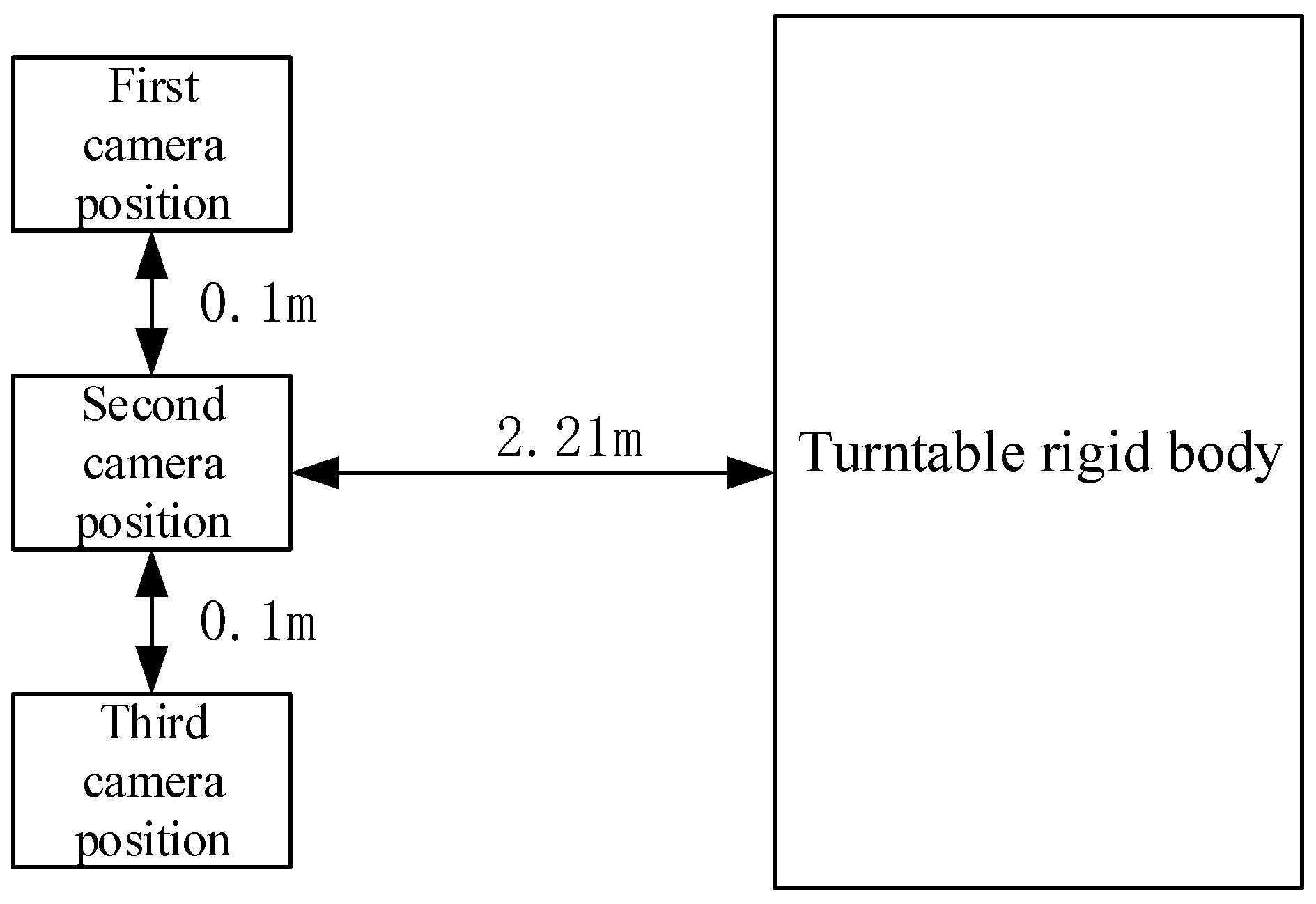
In verifying the ability to make repeated measurements adopting the proposed method, the camera was placed at three positions to measure the swing mode of the central axis of the turntable. These three positions were set parallel to the measured object at intervals of 0.1 m. As the camera used a Nikon F series variable-focal-length lens, the quality of the image was guaranteed by adjusting the focal length within a certain range. The camera was thus placed at any position perpendicular to the rigid body being photographed, and the measured distance from this position to the rigid body was 2.21 m, as shown in Figure 6.
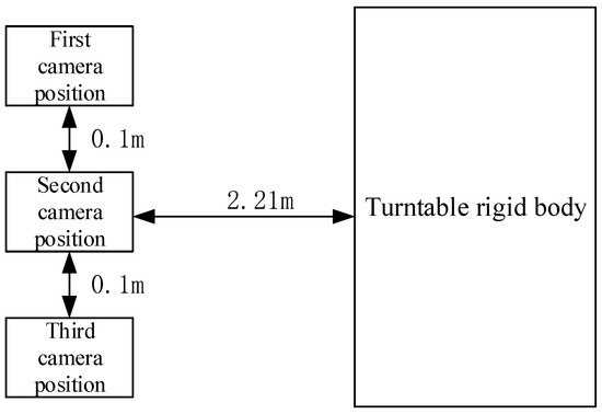
Figure 6.
Camera positions in the repeated measurements.
3.3.1. Attitude Measurement and Analysis
We used the high-speed camera to record video frames of dynamic changes in the middle and outer frames of the turntable. To ensure that the pixel coordinate measurement did not affect the pose measurements, the pixel coordinates of the control points were determined using TEMA, an advanced motion analysis tool developed by Image Systems AB in Sweden. We adopted the DLT method mentioned earlier for measurements and then used Equations (4) and (6) to obtain the attitude of the turntable. Dynamic changes in the attitude of the turntable are shown in Figure 7.
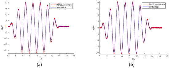

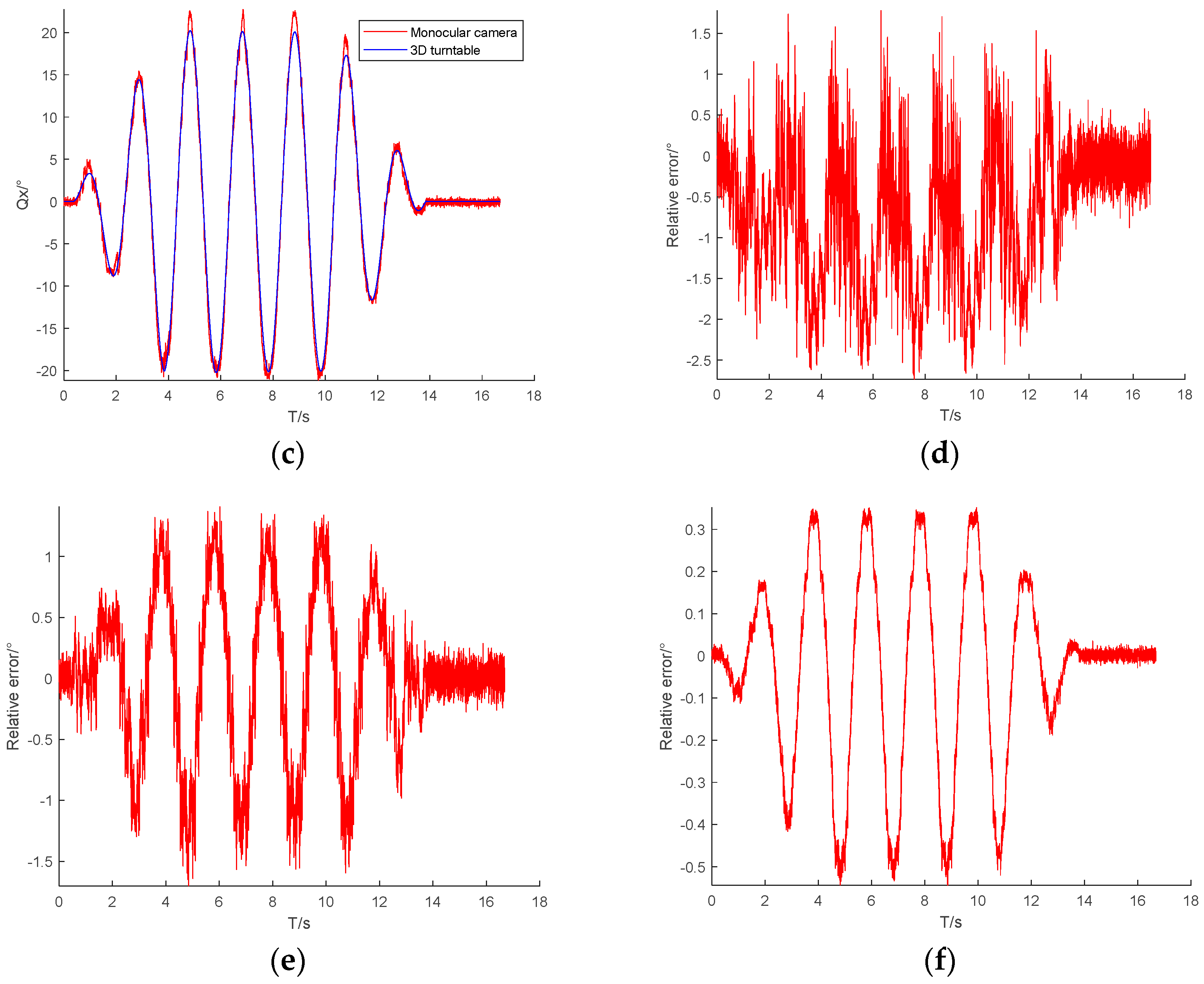
Figure 7.
Attitude angle in turntable swing mode. (a) Attitude angle in the first position; (b) Attitude angle in the second position; (c) Attitude angle in the third position; (d) Error of in the first position; (e) Error of in the first position; (f) Error of in the first position.
Figure 7 shows the change in the measured attitude angle of the rigid body when the camera is at a distance of 2.21 m. Figure 7a–c shows the real-time change in the camera’s attitude angle of the middle frame of the turntable measured for different camera positions. Table 1 compares the mean absolute error and standard deviation of the camera’s attitude angle measured for the three camera positions. Figure 7a–c and Table 1 reveal the minimum error in the attitude angle measured by the camera at the second camera position. The mean absolute error difference of the attitude angle measured at three positions is not significant (not more than 0.2 degrees). Figure 7d reflects the error of the camera in measuring the attitude angle at the first position. The error increases with the tilt of the rigid body relative to the camera lens. The mean absolute error is 0.8092 degrees, the standard deviation is 0.6623 degrees, and there are individual errors as large as 2.5 degrees. Figure 7e,f shows that although only one attitude angle is changing in theory, the angles and measured by the camera still include errors. The mean absolute error is 0.186 degrees, and the standard deviation is 0.641 degrees for , and the mean absolute error is −0.032 degrees and the standard deviation is 0.222 degrees for .

Table 1.
Control point parameters measured by the total station instrument.
3.3.2. Comparison Experiment of Attitude Measurements
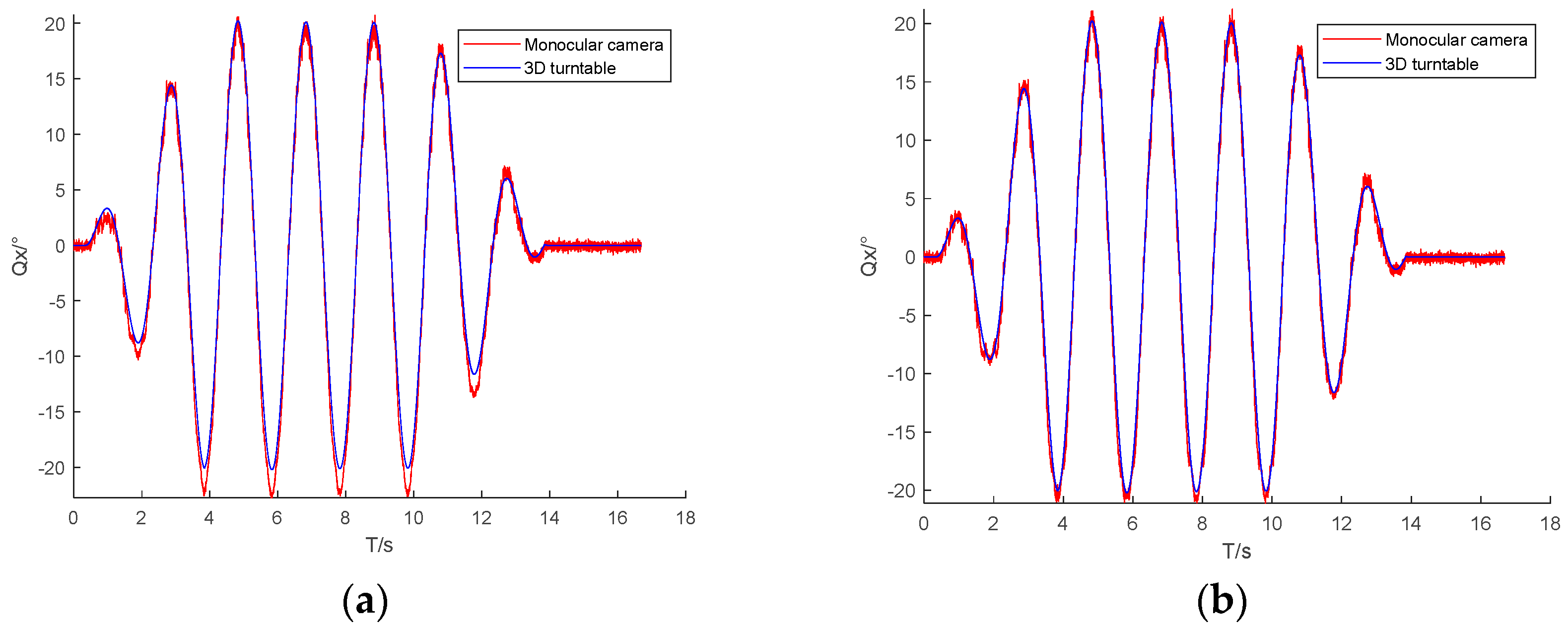
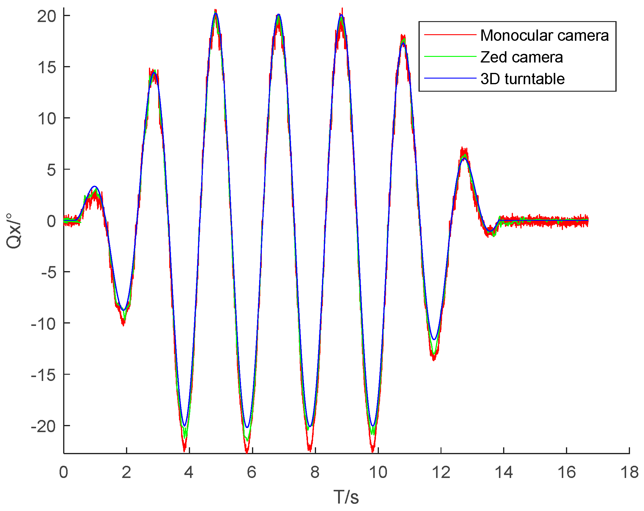
Binocular cameras have great applications in the field of attitude measurement. A Zed binocular camera was thus used in a comparative experiment. The Zed camera was set to 720p mode with a resolution of 1280 × 720 and a frame rate of 30 frames/s. The experiment took the middle frame of the turntable as the object, and the parameter settings of the turntable and high-speed camera were the same as those above. With the three-dimensional turntable in swing motion mode, we used a high-speed camera and a Zed camera to simultaneously record video frames of the dynamic changes of the turntable. The monocular, binocular, and turntable attitude measurements are shown in Figure 8.
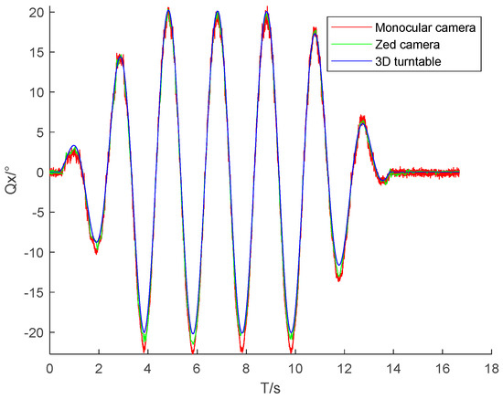
Figure 8.
Comparison of results obtained for the attitude angle Qx in the medium frame swing mode.
Figure 8 shows that the attitude angle dynamically measured using the monocular camera is consistent with the attitude angles measured using the Zed camera and three-dimensional turntable. Relative to the turntable measurements, the error in the attitude angle measured using the monocular camera was similar to the error in the attitude angle measured using the binocular camera, and the fluctuation was greater than that for the binocular camera. However, monocular cameras have better real-time performance and lower costs than binocular cameras.
3.3.3. Measurement and Analysis of the Position of the Center of Gravity of the Rigid Body
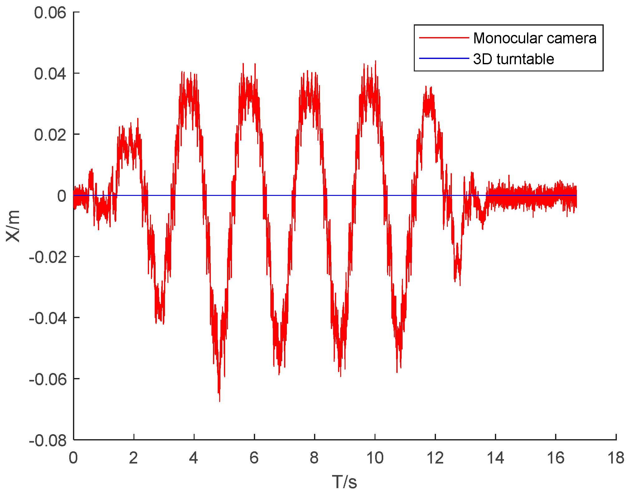
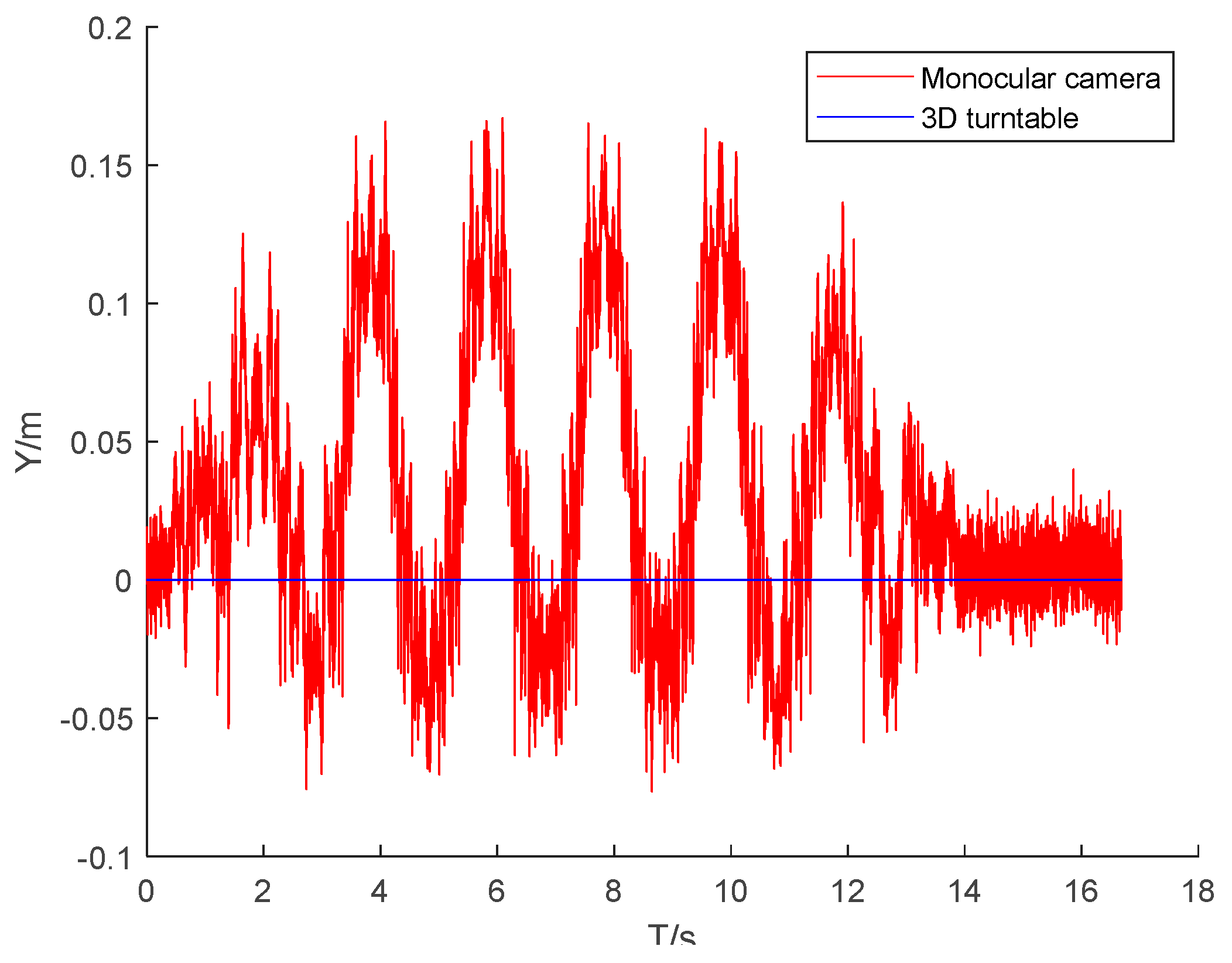
The DLT method mentioned earlier was used to measure , , , and . The centroid coordinates of the rigid body were , and the real-time position changes were calculated using Equation (3).
Figure 9, Figure 10 and Figure 11 present the three-dimensional coordinate changes of the body’s center of mass as measured by the monocular camera at the first position. It is seen that the error in the three-dimensional position of the center of mass of the rigid body increased with the tilt of the rigid body relative to the camera lens. This is because the constraint of the non-coplanar control points on the rigid body decreased, and the imaging quality of the control points deteriorated when the tilt ratio increased. The error in the X-axis coordinate of the rigid body center was much smaller than the errors in the other two axis coordinates because the middle-frame swinging motion of the rigid body involved rotation around the X-axis, and all control points had the best X-axis constraint during the motion.
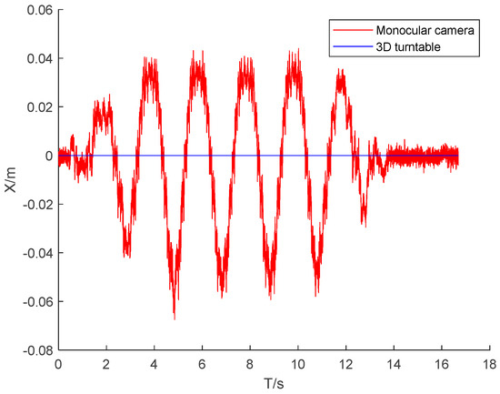
Figure 9.
Centroid X-coordinate versus time for the first camera position.
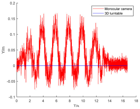
Figure 10.
Centroid Y-coordinate versus time for the first camera position.
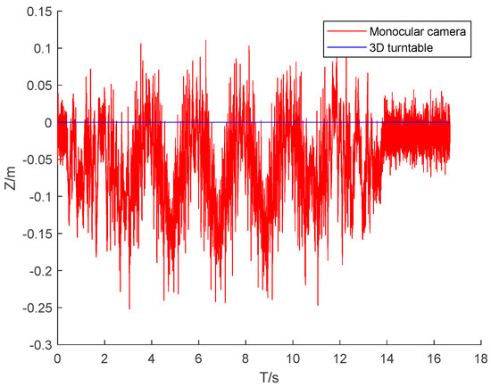
Figure 11.
Centroid Z-coordinate versus time for the first camera position.
Table 2 gives the errors in the camera measurements made at the three camera positions. The error in the coordinates of the center of mass was small for the three camera positions. The maximum deviation of the mean absolute error was 0.53 cm, and the maximum deviation of the standard deviation was 0.66 cm, indicating that the measurement process was insensitive to the camera position and that repeated measurements could be made.
Table 2.
Errors in the centroid three-dimensional coordinates for different camera positions.
4. Conclusions
This article systematically derived a method of measuring the absolute pose of a moving rigid body using a monocular camera based on a camera imaging model. A turntable test was conducted to verify that the proposed method could accurately measure position and attitude in repeated measurements within the visual range of the camera. The mean absolute error in the attitude angle measured at different camera positions varied by no more than 0.2 degrees. The error in the attitude angle measured by the camera at the first camera position increased with the tilt angle of the rigid body relative to the camera lens. The mean absolute error was 0.8092 degrees, the standard deviation was 0.6623 degrees, and there were individual errors up to 2.5 degrees. An analysis of the error in the coordinates of the center of mass position showed that the deviation of the measurements across the three camera positions was small, the maximum deviation of the mean absolute error was 0.53 cm, and the maximum deviation of the standard deviation was 0.66 cm. The measurement was thus insensitive to the camera placement, and repeated measurements could be made. Although the proposed method requires the placement of two sets of marker points, which may be infeasible, it is suitable for non-professional and low-cost measurement applications.
Author Contributions
Conceptualization, S.G.; methodology, S.G. and Z.Z.; validation, S.G. and L.G.; formal analysis, Z.Z.; investigation, M.W. and L.G.; resources, Z.Z.; writing—original draft preparation, S.G. and M.W.; writing—review and editing, L.G. and Z.Z.; visualization, S.G. and L.G.; supervision, Z.Z. and M.W.; project administration, S.G.; funding acquisition, Z.Z. All authors have read and agreed to the published version of the manuscript.
Funding
This research was supported by the Common Key Technology R&D Innovation Team Construction Project of Modern Agriculture of Guangdong Province, China (grant no. 2021KJ129).
Institutional Review Board Statement
Not applicable.
Informed Consent Statement
Not applicable.
Data Availability Statement
Restrictions apply to the availability of the data. Data can be obtained from the first author.
Conflicts of Interest
The authors declare no conflict of interest.
References
- Chen, J.; Zhao, Z.; Shi, L.; Ke, X.; Wu, Z.; Liu, X. Dynamic modeling of leveling system of paddy field laser leveler. Trans. Chin. Soc. Agric. Eng. 2015, 31, 18–23. [Google Scholar]
- Zhao, Z.X.; Tu, H.; Feng, R.; Song, J.W. Dynamic modeling and verification of paddy leveler based on rigid flexible coupling multibody systems. Trans. Chin. Soc. Agric. Eng. 2017, 33, 27–33. [Google Scholar]
- Wei, Y.; Ding, Z.R.; Huang, H.C.; Yan, C.; Huang, J.X.; Leng, J.X. A non-contact measurement method of ship block using image-based 3D reconstruction technology. Ocean Eng. 2019, 178, 463–475. [Google Scholar] [CrossRef]
- Luo, H.; Zhang, K.; Su, Y.; Zhong, K.; Li, Z.W.; Guo, J.; Guo, C. Monocular vision pose determination-based large rigid-body docking method. Measurement 2022, 204, 112049. [Google Scholar] [CrossRef]
- Audira, G.; Sampurna, B.P.; Juniardi, S.; Liang, S.T.; Lai, Y.-H.; Hsiao, C.D. A Simple Setup to Perform 3D Locomotion Tracking in Zebrafish by Using a Single Camera. Inventions 2018, 3, 11. [Google Scholar] [CrossRef]
- Chen, X.; Yang, Y.H. A Closed-Form Solution to Single Underwater Camera Calibration Using Triple Wavelength Dispersion and Its Application to Single Camera 3D Reconstruction. IEEE Trans. Image Process. 2017, 26, 4553–4561. [Google Scholar] [CrossRef]
- Wang, P.; Sun, X.H.; Sun, C.K. Optimized selection of LED feature points coordinate for pose measurement. J. Tianjin Univ. Nat. Sci. Eng. Technol. Ed. 2018, 51, 315–324. [Google Scholar] [CrossRef]
- Sun, C.; Sun, P.; Wang, P. An improvement of pose measurement method using global control points calibration. PLoS ONE 2015, 10, e0133905. [Google Scholar] [CrossRef]
- Adachi, T.; Hayashi, N.; Takai, S. Cooperative Target Tracking by Multiagent Camera Sensor Networks via Gaussian Process. IEEE Access 2022, 10, 71717–71727. [Google Scholar] [CrossRef]
- Wang, Y.; Yuan, F.; Jiang, H.; Hu, Y.H. Novel camera calibration based on cooperative target in attitude measurement. Optik 2016, 127, 10457–10466. [Google Scholar] [CrossRef]
- Wang, X.J.; Cao, Y.; Zhou, K. Methods of monocular pose measurement based on planar objects. Opt. Precis. Eng. 2017, 25, 274–280. [Google Scholar] [CrossRef]
- Sun, D.; Hu, L.; Duan, H.; Pei, H. Relative Pose Estimation of Non-Cooperative Space Targets Using a TOF Camera. Remote Sens. 2022, 14, 6100. [Google Scholar] [CrossRef]
- Peng, J.; Xu, W.; Liang, B.; Wu, A.G. Pose Measurement and Motion Estimation of Space Non-Cooperative Targets Based on Laser Radar and Stereo-Vision Fusion. IEEE Sens. J. 2019, 19, 3008–3019. [Google Scholar] [CrossRef]
- Peng, J.; Xu, W.; Yan, L.; Pan, E.; Liang, B.; Wu, A.G. A Pose Measurement Method of a Space Noncooperative Target Based on Maximum Outer Contour Recognition. IEEE Trans. Aerosp. Electron. Syst. 2020, 56, 512–526. [Google Scholar] [CrossRef]
- Su, J.D.; Qi, X.H.; Duan, X.S. Plane pose measurement method based on monocular vision and checkerboard target. Acta Opt. Sin. 2017, 37, 218–228. [Google Scholar] [CrossRef]
- Yang, X.W.; Liu, T.Y. Moving object detection algorithm based on improved visual background extractor. J. Phys. Conf. Ser. 2021, 1732, 012078. [Google Scholar] [CrossRef]
- Chen, Z.K.; Xu, A.; Wang, F.B.; Wang, Y. Pose measurement of target based on monocular vision and circle structured light. J. Appl. Opt. 2016, 37, 680–685. [Google Scholar] [CrossRef]
- Li, J.; Besada, J.A.; Bernardos, A.M.; Tarrío, P.; Casar, J.R. A Novel System for Object Pose Estimation Using Fused Vision and Inertial Data. Inf. Fusion 2016, 33, 15–28. [Google Scholar] [CrossRef]
- Wang, X.; Yu, H.; Feng, D. Pose estimation in runway end safety area using geometry structure features. Aeronaut. J. 2016, 120, 675–691. [Google Scholar] [CrossRef]
- Tang, S.; Dong, Z.; Feng, W.; Li, Q.; Nie, L. Fast and accuracy camera calibration based on Tsai two-step method. In Proceedings of the 2021 7th International Conference on Mechatronics and Robotics Engineering (ICMRE), Budapest, Hungary, 3–5 February 2021; pp. 190–194. [Google Scholar] [CrossRef]
- Fischler, M.A.; Bolles, R.C. Random sample consensus: A paradigm for model fitting with applications to image analysis and automated cartography. Read. Comput. Vis. 1987, 24, 726–740. [Google Scholar] [CrossRef]
- Zhang, Z. A flexible new technique for camera calibration. IEEE Trans. Pattern Anal. Mach. Intell. 2000, 22, 1330–1334. [Google Scholar] [CrossRef]
- Guo, Y.; Xu, X.H. An analytic solution for the P5P problem with an uncalibrated camera. Chin. J. Comput. 2007, 30, 1195–1200. [Google Scholar]
- Hartley, R.; Zisserman, A. Multiple View Geometry in Computer Vision; Cambridge University Press: Cambridge, UK, 2011. [Google Scholar] [CrossRef]
- Lepetit, V.; Noguer, F.M.; Fua, P. EPnP: An accurate O(n) solution to the PnP problem. Int. J. Comput. Vis. 2009, 81, 155–166. [Google Scholar] [CrossRef]
- Ni, X.; Zhou, C.; Tian, H. An optimized POSIT algorithm based on mean convergence. In Proceedings of the 2021 International Conference on Communications, Information System and Computer Engineering (CISCE), Beijing, China, 14–16 May 2021; pp. 636–640. [Google Scholar]
- Wang, K.; Yu, Z.H.; Liu, H.; Li, R.; Guo, B. Motion and Structure Estimation of Non-Cooperative Space Target Based on Tri-EKF Algorithm and Stereo Vision. J. Astronaut. 2017, 38, 936–945. [Google Scholar] [CrossRef]
- Zhao, L.K.; Zheng, S.Y.; Wang, X.N.; Huang, X. Rigid object position and orientation measurement based on monocular sequence. J. Zhejiang Univ. Eng. Sci. 2018, 52, 2372–2381. [Google Scholar] [CrossRef]
- Zhao, L.J.; Liu, E.H.; Zhang, W.M.; Zhao, R.J. Analysis of position estimation precision by cooperative target with three feature points. Opt. Precis. Eng. 2014, 22, 1190–1197. [Google Scholar] [CrossRef]
- Ji, J.H.; Huang, X.M. Insight probe set out to explore the inner world of Mars. Chin. Sci. Bull. 2018, 63, 2678–2685. [Google Scholar] [CrossRef]
- Song, W.; Zhou, Y. Estimation of monocular vision 6-DOF pose based on CAD model. Opt. Precis. Eng. 2016, 24, 882–891. [Google Scholar] [CrossRef]
- Bronislav, P.; Pavel, Z.; Martin, C. Absolute pose estimation from line correspondences using direct linear transformation. Comput. Vis. Image Underst. 2017, 161, 130–144. [Google Scholar] [CrossRef]


Disclaimer/Publisher’s Note: The statements, opinions and data contained in all publications are solely those of the individual author(s) and contributor(s) and not of MDPI and/or the editor(s). MDPI and/or the editor(s) disclaim responsibility for any injury to people or property resulting from any ideas, methods, instructions or products referred to in the content. |
© 2023 by the authors. Licensee MDPI, Basel, Switzerland. This article is an open access article distributed under the terms and conditions of the Creative Commons Attribution (CC BY) license (https://creativecommons.org/licenses/by/4.0/).